

Page 1

TABLE OF CONTENTS
CUSTOMER MESSAGE Inside Front Cover
SAFETY PRECAUTIONS 3
GENERAL DESCRIPTION 6
92-0630 Rev. 130308
Model 301 Tube Squaring Machine
SPECIFICATIONS 8
MAINTENANCE 10
OPERATION 11
INSTALLING THE QL 21
CUTTING SPEEDS AND FEEDS 22
COLLETS 24
TOOL BITS 28
TROUBLE SHOOTING 30
ACCESSORIES 32
ILLUSTRATED PARTS BREAKDOWN 33
DEWALT SAFETY INSTRUCTIONS 40
TOOL BIT RESHARPENING POLICY Inside Back Cover
WARRANTY INFORMATION Inside Back Cover
Page 2

Copyright 2013
Proprietary property of TRI TOOL INC.
No reproduction, use, or duplication of the information
shown hereon is permitted without the express written
consent of TRI TOOL INC.
Page 3

SAFETY PRECAUTIONS
IN GENERAL
When using rotating head cutting equipment, basic safety precautions should always
be followed to reduce the risk of personal injury.
Operate this tool only in accordance with specic operating instructions.
Do not override the deadman switch on the power unit. Locking down,
WARNING:
DRESS CONSIDERATIONS
obstructing, or in any way defeating the deadman switch on the power drive
unit may result in serious injury.
Model 301 Tube Squaring Machine
Use standard safety equipment. Hard hats, safety shoes, safety harnesses,
protective clothes, and other safety devices should always be used when
appropriate.
Use safety glasses. Do not operate cutting tools without eye protection.
Dress properly. Do not wear loose clothing or jewelry. They can be caught in
rotating and moving parts. Avoid slippery oors or wear nonskid footwear. If you
have long hair, wear protective hair covering to contain it.
WORK AREA
Keep the work area clean. Cluttered work areas and benches invite injuries.
Consider the work area environment. Keep the area well lit. Keep electrical cords,
cables, rags, rigging straps, and etc. clear of rotating equipment. Do not use power-
cutting tools in the presence of ammable liquids and gasses.
Keep visitors away. Do not let visitors or untrained personnel at or near operating
tools. Enforce eye protection requirements for all observers.
Do not over reach. Keep proper footing at all times.
Stay alert. Watch what you are doing. Use common sense. Do not operate tools
when you are tired.
92-0630 Rev. 130308
3
Page 4

TRI TOOL INC.
TOOL CARE
Maintain tools with care. Keep tools in good operating condition. Sharp tool bits
perform better and safer than dull tool bits. Well maintained tools function properly
when needed.
Check for damaged parts. If a tool has malfunctioned, been dropped or hit, it
must be checked for damage. Run no-load tests and feed function checks. Do a
complete visual inspection.
Electric motors. Use only with proper AC voltage power sources and observe all
normal electric shock hazard procedures.
Do not abuse power and control cords. Pulling or running over cords and cables can
result in electrical shock hazards and malfunctions. Keep control and power cords
out of all cutting uids and water.
Hydraulic drives. Observe proper procedures for electrically driven power sources.
Avoid damage to hydraulic lines. Keep quick-disconnects clean. Grit contamination
causes malfunctions.
Air tools. Check the exhaust mufer. Broken or damaged mufers can restrict
air ow or cause excessive noise. Use air motors only with a ltered, lubricated
and regulated air supply. Dirty air, low-pressure air or over pressure air will cause
malfunctions, including delayed starting.
AREA EQUIPMENT
Secure work. Whenever possible use clamps, vises, chains and straps to secure
pipe.
12n
Make sure the tool is secured; it is safer to have both hands free to operate the tool.
TOOL USE
Use the right tool and tool bit for the job. Do not use a tool, which is incorrect for the
job you are doing.
Keep the tool bits fully engaged in the tool bit holders. Loose bits are a safety
hazard.
4
92-0630 Rev. 130308
Page 5

Model 301 Tube Squaring Machine
Disconnect power supply during setup and maintenance. Use all ‘Stop’ or Shut off’
features available when changing or adjusting tool bits, maintaining the tool, or when
the tool is not in use.
Remove adjusting keys and wrenches before applying power to the equipment.
Develop a habit of checking the tool before turning it on to make sure that all keys
and wrenches have been removed.
Do not force tools. Tools and tool bits function better and safer when used at the
feed and speed rate for which they were designed.
Do not reach into rotating equipment. Do not reach into the rotating head stock to
clear chips, to make adjustments, or to check surface nish. A machine designed to
cut steel will not stop for a hand or an arm.
Handle chips with care. Chips have very sharp edges and are hot. Do not try to pull
chips apart with your hands; they are very tough.
Avoid unintentional starts. Do not carry or handle tools with your hand on the
operating switches or levers. Do not lay the tool down in a manner that will start the
drive. Do not allow the tool to ip around or move when adjusting or changing tool
bits.
Store idle tools properly. Disconnect tools from the power source and store in a safe
place. Remove tool bits for safe handling of the tool.
92-0630 Rev. 130308
5
Page 6

TRI TOOL INC.
GENERAL DESCRIPTION
The Model 301*, Tube Squaring Machine is a lightweight portable machine designed
for facing and squaring .125” to 1.102” (3.2 mm to 28.0 mm) outside diameter tubing
with an ability to handle up to .125” (3.2 mm) thick wall.
The Model 301 Tube Squaring Machine has several Motor options.
There is an integral, variable speed Air Motor.
There is an integral, variable speed 110 VAC, 500 watt Electric Motor.
There is an integral, variable speed 220 VAC, 500 watt Electric Motor.
There is a Battery supported DC Electric Motor.
Precision inside diameter Collets hold the tubing round to accurately square and
face the tubing with a minimum burr.
The portable version uses a Nut to retain the Collet.
There is a Quick Lock Clamp System to retain the Collet available.
This Machine accepts its own torque through the Collet clamping system.
The Cutting Head accepts Squaring Tool Bits or combinations of Squaring, Beveling
or ID deburring Tool Bits.
All required tools for operation of the Model 301 are supplied with the Machine or
with the accessory Collet Adapters.
6
92-0630 Rev. 130308
Page 7

Model 301 Tube Squaring Machine
*DESIGNATIONS FOR THE MODEL 301
Model No. Part No. Description
301A 01-1203 Tube Squaring Machine powered by an Air Motor
301AQL 01-1322
301BDC 01-1325
301E110 01-1205 Tube Squaring Machine with a 110 VAC Electric Motor
301E110QL 01-1323
301E220 01-1207 Tube Squaring Machine with a 220 VAC Electric Motor
301E220QL 01-1324
Tube Squaring Machine with a Quick Lock attachment
powered by an Air Motor
Tube Squaring Machine with 14.4 V Battery
powered Motor
Tube Squaring Machine with a Quick Lock attachment
with a 110 VAC Electric Motor
Tube Squaring Machine with a Quick Lock attachment
with a 220 VAC Electric Motor
92-0630 Rev. 130308
7
Page 8
TRI TOOL INC.
SPECIFICATIONS
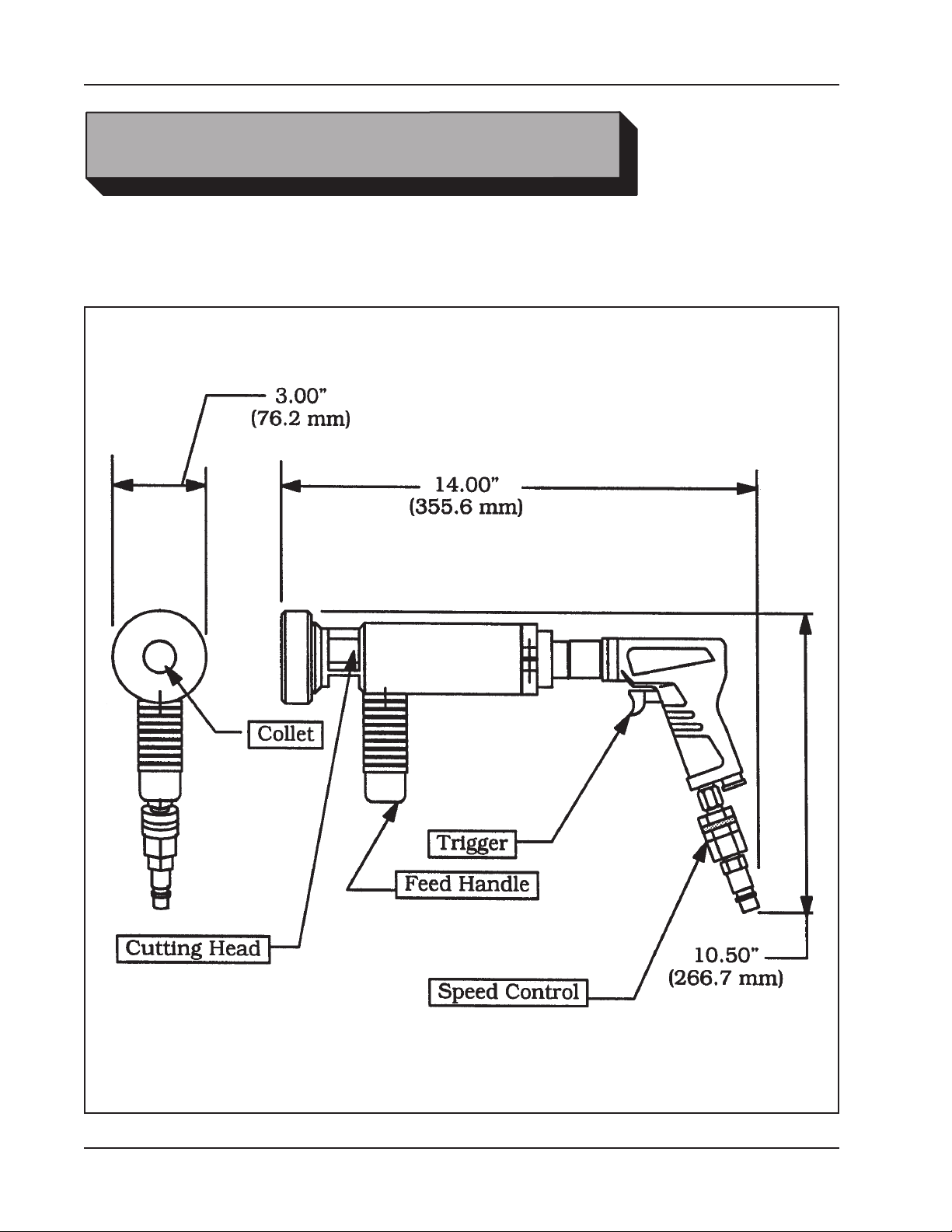
Model 301 with an Air Motor:
Weight: 6.75 lbs. (3.1 kg) (varies slightly with Collet size)
Power requirements: 22 cfm at 90 psi (10 L/s at kPa)
Envelope, Model 301A Tube Squaring Machine
8
92-0630 Rev. 130308
Page 9
Model 301 Tube Squaring Machine
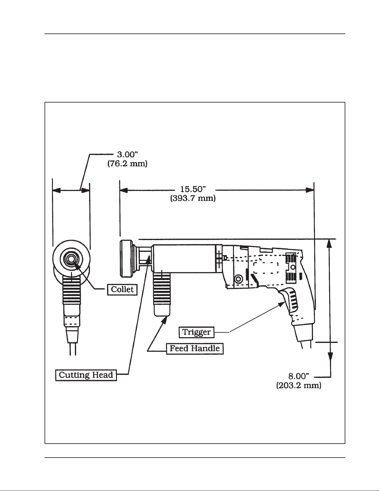
Model 301 with an Electric Motor:
Weight: 6.8 lbs. (3/1 kg) (varies slightly with Collet size)
Power Requirements:
Model 301E110 115 VAC +10%, 25 to 60 Hz
Model 301E220 220 VAC +10%, 25 to 50 Hz
Envelope, Model 301E Tube Squaring Machine
92-0630 Rev. 130308
9
Page 10
TRI TOOL INC.
MAINTENANCE
All components should be cleaned and coated with a light lm of oil prior to use.
Use a clean, non-detergent oil, preferably SAE 10 (90 SSU) or lighter.
If the Model 301 is operated in the vertical position (Cutting Head up), it should be
turned upside down and the chips and/or other debris removed after each bevel has
been completed.
Tool life may be severely shortened, unless chips and/or other debris that
NOTE:
have been deposited on the Cutting Head during the machining operation are
removed.
Disassembly of a power unit voids warranty, except when performed by a
NOTE:
TRI TOOL Inc. designated repair technician.
Clean-Up
10
92-0630 Rev. 130308
Page 11

Model 301 Tube Squaring Machine
OPERATION
Select the tool bit(s) required to machine the end conguration desired.
Use of dull or improperly designed Tool Bits or Tool Bits not manufactured by
WARNING:
TRI TOOL Inc. may result in poor performance and may constitute abuse of
this machine and therefore voids the TRI TOOL Inc. factory warranty.
GENERAL GUIDE LINES FOR SELECTING A TOOL BIT
Selection of the Tool Bit should be based on tubing material, the tubing size, and
how critical is it to have a near burr free end.
A standard entrance angle Tool Bit is recommended for carbon steel.
These Tool Bits also function well with some stainless steel applications where a
near burr free end is not a critical requirement.
A high entrance angel Tool Bit is recommended for most stainless steels.
Generally this is the most suitable edge geometry for about 90 % of all of the
stainless steel tubing applications.
An extra hook angle Tool Bit is recommended for stainless steels which are very
soft.
These stainless steels include materials like 316L, which have been bright hydrogen
annealed, vacuum annealed or annealed and electro-polished.
Electro-polished stainless steel has a micro-thin surface, which is high in Cr and Ni
which makes it very soft, but tough and difcult to cut without a burr.
Use a .969” (24.6 mm) tall Tool Bit for 3/16” (4.7 mm) diameter or less tubing.
The tall Tool Bit may provide some advantages for wall thicknesses less than
.020” (.5 mm).
The tall Tool Bit will cut very close to the Collet face, which minimizes exing of the
tubing from the cutting pressure.
The tall Tool Bit will require more time to adjust the tubing position for cutting and
there is some risk of crashing the Tool Bit into the Collet on larger OD tubing.
92-0630 Rev. 130308
11
Page 12

TRI TOOL INC.
The M-42 Tool Bits are for use with the exotic alloys where the high heat resistance
is required to avoid burning the cutting edge of the Tool Bit.
M-42 can improve the life expectancy of the Tool Bit under some conditions on
stainless steel.
It should be noted that M-42 Tool Bits are more brittle than the M-2 Tool Bits,
therefore there is a much greater risk of damaging the M-42 Tool Bit when installing
the tubing in the Tube Squaring Machine.
Loss of Tool Bits from damaged edges may not off-set the improved cutting life that
those Tool Bits promise.
Some of the exotic alloys may require Tool Bits with both the extra hook angle as
well as the M-42 tool steel for heat resistance.
Insert the Tool Bit into the slot in the Cutting Head.
Ensure that the Model 301 is disconnected from the power source before
CAUTION:
installing a Tool Bit.
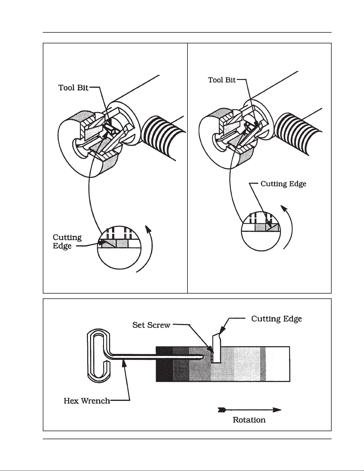
The normal position for the Tool Bit (P/N 99-1445) is shown in following picture.
This position is used for .50” (12.7 mm) and smaller diameter tubing.
This is the designed working position of the Tool Bit and will leave virtually no burr
with standard tubing.
When working with electro-polished stainless steel tubing, slow cutting speeds must
be used to minimize the ID burr.
The Tool Bit (P/N 99-1445) may be reversed as shown in the following pictures.
This reversed position may be used for tubing with an ID greater than .50"
(12.7mm).
With the extreme shear cutting action, the burr on the ID will be virtually eliminated.
Minimum burr may be obtained with a slow RPM and a slow feed, which will
NOTE:
cut a continuous chip.
Terminate the cut with one or two revolutions without feed to square the end of the
tubing.
The cutting edge of the Tool Bit must be located on the radial centerline.
CAUTION:
12
92-0630 Rev. 130308
Page 13
Model 301 Tube Squaring Machine
Tool Bit Installed With The
Cutting Edge Out
Tool Bit Installed With The
Cutting Edge In
Tool Bit Tightening
92-0630 Rev. 130308
13
Page 14
TRI TOOL INC.
Do NOT install the Tool bit backwards.
Tighten the Set Screws to secure the Tool bit to the Cutting Head.
Select the proper size Collet for the outside diameter of the tube or pipe to be
squared.
The size of the Collet is determined by the outside diameter of the tube or
NOTE:
pipe to be squared.
CAUTION:
Do not drop the Collet.
Always place a hand under the Collet when installing or removing it from the
Model 301.
INSTALLING A COLLET IN THE MODEL 301
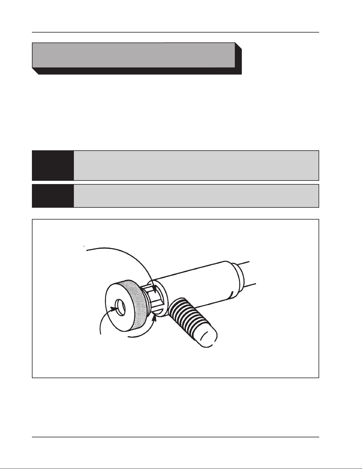
Remove the Knurled Nut from the end of the Model 301.
Insert the Collet into the tapered end of the Model 301.
Screw the Knurled Nut back onto the Model 301.
Be sure that there is a light lm of grease on Knurled Nut threads at all times
WARNING:
to prevent them from galling or freezing during use.
Back the Knurled Nut off just enough to allow insertion of the tube or pipe into the
Collet.
Partially tighten the Knurled Nut until the tube or pipe may still be moved into
position.
Move the tube or pipe approximately 1/16” (1.6 mm) from the Tool Bit.
As the Collet closes, the tube is drawn toward the Tool Bit.
NOTE:
Do not let the Tool Bit touch the tube or pipe.
CAUTION:
To do so will cause damage to the Tool Bit or the Tube Squaring Machine when
power is applied.
Tighten the Knurled Nut to prevent the rotation of the tube or pipe during machining.
14
92-0630 Rev. 130308
Page 15

Model 301 Tube Squaring Machine
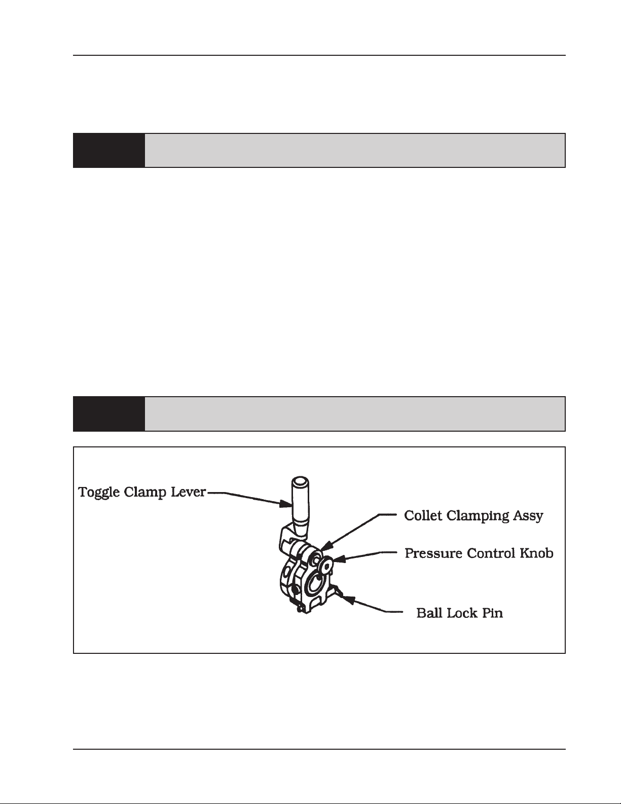
INSTALLING A COLLET IN THE MODEL 301QL
Remove the Ball Lock Pin from the Collet Clamping Assy of the Model 301QL by
pulling straight out.
Be sure that the Toggle Clamp Lever is in the up position to allow the pin to
NOTE:
be pulled out.
Swing the Clamping Head Assy upward to allow the Collet to be slid into place.
Insert the Collet into the tapered Collet Clamping Model 301QL.
Swing the Collet Clamping Assy down into position.
Insert the Ball Lock Pin completely into the hole provided for it in the Collet clamping
Assy.
Be sure that the Toggle Clamp Lever is in the up position in order to permit
NOTE:
the pin to be pushed into the Collet Clamping Assy.
Insert the pipe or tube to be machined into the Collet.
Verify a clearance of 1/16” (1.6 mm) between the Tool Bits(s) and the pipe or tube
face as held by the Collet.
NOTE:
As the Collet closes, the tube is drawn toward the Tool bit.
Do not let the Tool Bit touch the pipe or tube at this time.
CAUTION:
To do so will cause damage to the Tool Bit or the Tube Squaring Machine when
power is applied.
Lock the tube or pipe in position by pushing the Toggle Clamp Lever all of the way
down.
Attach the power supply to the Model 301 and pull the Trigger to start rotation of the
Cutting Head
POWER REQUIREMENTS
Power requirements for a Model 301 equipped with an Air Motor.
The air supply should be 22 cfm at 90 psi (10 L/s at 621 kPa).
NOTE:
92-0630 Rev. 130308
15
Page 16
TRI TOOL INC.
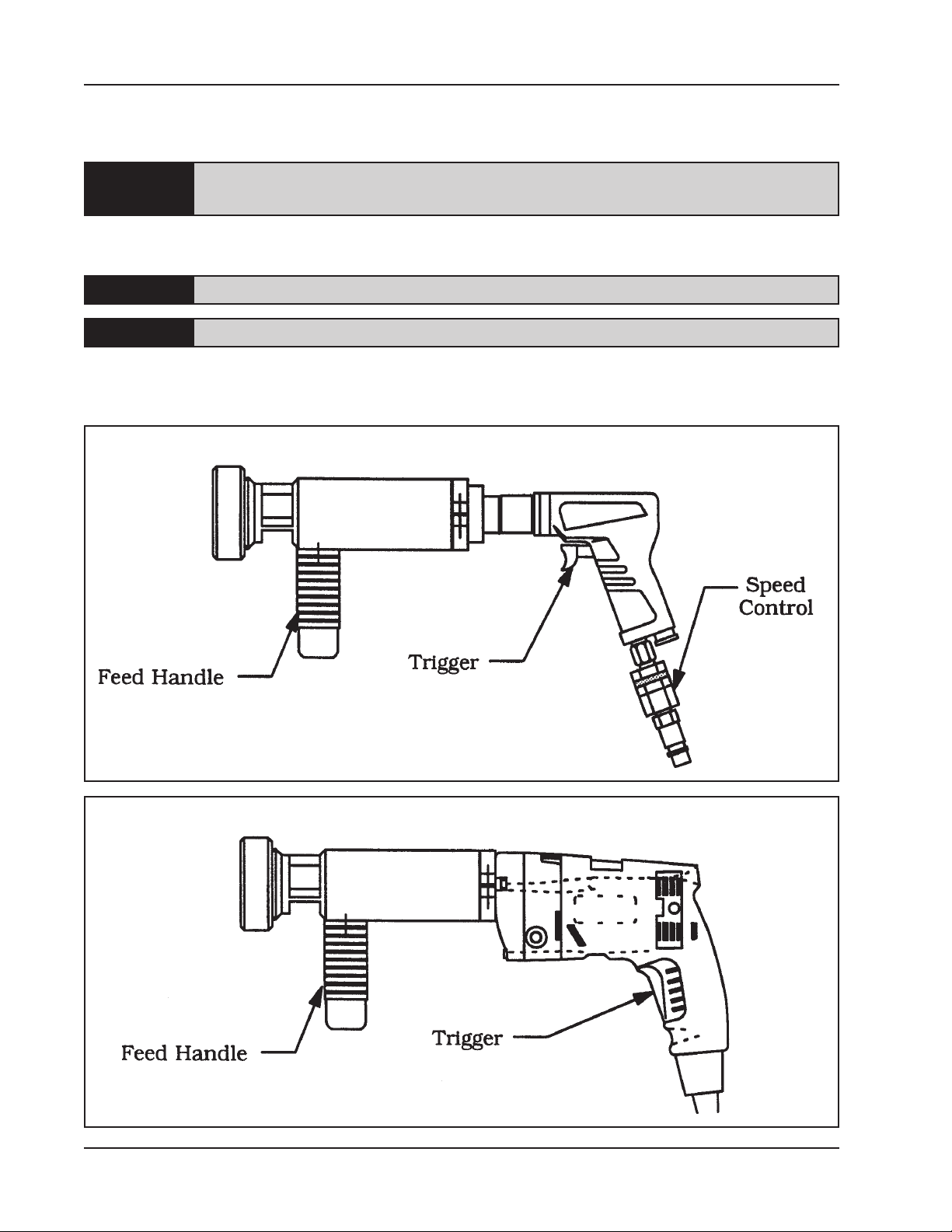
Connect the Model 301 to the air supply and pull the trigger to start rotation of the
Cutting Head.
Ensure that the air supply has an adequate FRL (lter/regulator/lubricator)
NOTE:
installed and adjusted properly.
Power requirement for a Model 301 equipped with an Electric Motor.
The 110 VAC version will require a 110 VAC outlet.
NOTE:
The 220 VAC version will require a 220 VAC outlet.
NOTE:
Connect the Model 301 to the required power supply and pull the trigger to start
rotation of the Cutting Head.
Location of the Various Controls
Location of the Various Controls
16
92-0630 Rev. 130308
Page 17
Model 301 Tube Squaring Machine
ADJUSTMENT OF THE CUTTING SPEED
Use the Speed Control to adjust the cutting speed.
Refer to the section ‘Cutting Speeds and Feeds’ for the recommended cutting
NOTE:
speeds.
In order to obtain a minimum burr tube end, it is essential that heat build up be
avoided.
When either the tube or the Tool Bit gets hot then the tube material starts to ow or
push away from the Tool Bit edge in the form of a burr, instead of being cut cleanly
with a minimum burr.
Avoid the conditions, which generate excessive heat by:
Keep the RPM’s low; excessive cutting speed will generate unwanted heat.
Keep the chip curling loose; avoid excessive depth of cut.
Use a sharp Tool Bit; a dull Tool Bit just isn’t going to do the job right.
Rotate the Feed Handle clockwise to bring the Cutting Head and tube closer
together.
The actual machining operation will begin when the Tool Bit contacts the tube
CAUTION:
or pipe.
Location of the Various Controls
If the tube end is not square to the tube axis, the Tool Bit will contact only a small
segment of the pipe during each revolution.
To avoid Tool Bit damage, the feed rate should be very slow until the Tool Bit is
contacting the pipe continually during at least one revolution.
92-0630 Rev. 130308
17
Page 18

TRI TOOL INC.
Adjust the cutting RPM with the Speed Control to just above the required cutting
speed as the Tool Bit enters the cut.
The Tool will slow down slightly as the cutting load increases, apply additional power
to hold the cutting speed.
Observe the chip as the machine is cutting.
The ideal chip will come off in a loose pig tail spiral.
A chip that is coming off in a tight straight spiral normally indicates that the feed is
too heavy.
A straight or slightly curled chip normally indicates that the feed is too light.
Back off the feed as required to break the chips and let them fall away.
If a signicant amount of stock must be removed, occasionally back out of the cut
and let the Tool Bit spin free in the air to cool.
Continue rotating the Feed Handle clockwise until the end of the pipe is completely
machined.
Be careful not to let the Tool Bit cut into the Collet or the Collet Adapter.
CAUTION:
Discontinue feed and allow the Cutting Head to rotate one time for stainless steel
and up to three times for other materials to improve the nish of the prep
surface.
Never let a Tool Bit ‘rub’ the surface of a stainless steel tube without cutting.
This will work harden the material and it will be difcult for the Tool Bit to get under
the material in order to nish the cut.
This will also cause excessive Tool Bit wear.
Rotate the Feed Handle counter-clockwise to separate the Cutting Head and the
pipe.
Stop the Cutting Head rotation.
Release the Trigger.
Rotate the Feed Knob counter-clockwise until the Cutting Head clears the tube or
18
92-0630 Rev. 130308
Page 19
Model 301 Tube Squaring Machine
pipe by at least 1/8” (3.2 mm) or more.
On the Model 301 loosen the Collet Nut to release the tube or pipe.
On the Model 301QL pull the Toggle Clamp Lever back to release the tube or pipe.
If the next cut is to be identical to the previous cut, then follow the sequence starting
with ‘Installing a Collet in the Model 301’ earlier in this section.
If the next cut is to be different than the previous cut, disconnect the power cord and
then follow the sequence starting at the beginning of this section ‘Operation’.
End squaring of 1/8” (3.2 mm) diameter or smaller tubing with the Model 301.
End squaring small tubing with the Model 301 can be difcult due to the fact that the
cutting force causes the tube to ex.
Another problem is that it is difcult to get the tip of the Tool Bit into the bore of the
tube.
Resharpened Tool Bits will not work as the cutting edge has been moved away from
the center and therefore the cutting edge cannot be positioned in the bore of the
tube.
A taller Tool Bit can be used to minimize the length of the tubing, which is not
supported by the Collet.
This will reduce the exing of the tubing and in turn provide a cleaner cut with less
smearing or burr.
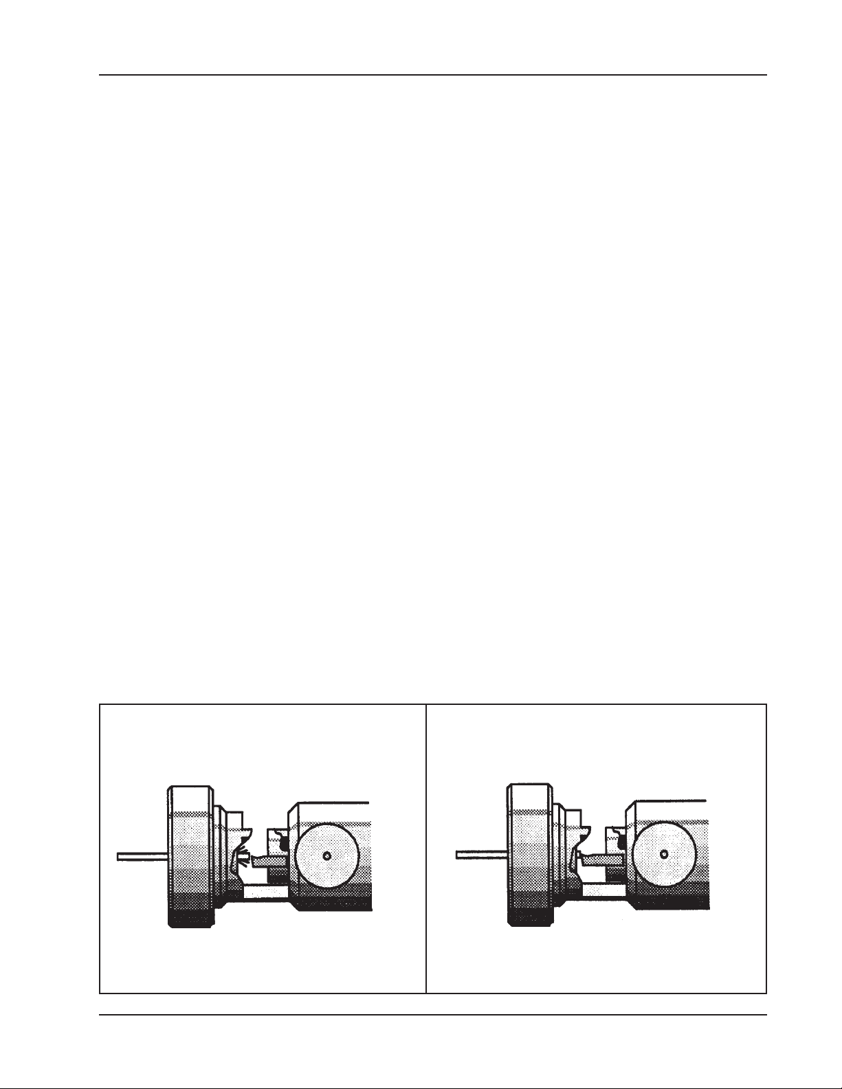
Tool Bit (P/N 99-2448) is a taller Tool Bit, which has extra hook to provide a very low
Tool Bit is too far from the tubing
Longer Tool Bit in use
92-0630 Rev. 130308
19
Page 20
TRI TOOL INC.
force cutting action.
This Tool Bit allows the tubing to be positioned in the Collet so that only 1/16”
(1.6 mm) to 1/8” (3.2 mm) is unsupported by the Collet at the cut line.
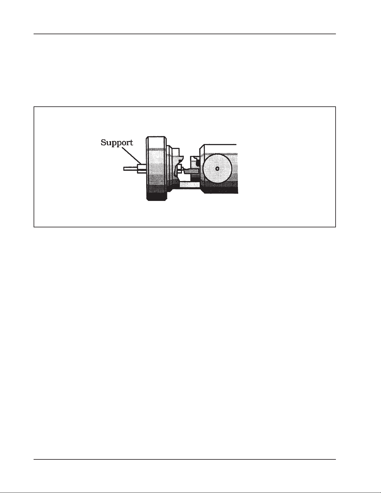
Another method is to use a consumable aluminum “pot chuck” which has been
made from approximately 6” (152 mm) lengths of 3/16” (4.8 mm), or 1/4” (6.4 mm)
Support added to the tubing
aluminum rod or tubing.
The rod or tubing is then bored and or reamed to match the OD of the tubing to be
squared.
A very ne longitudinal slit is then cut in the consumable pot chuck, which will allow
the Collet to clamp on the product tubing.
The product tubing along with the pot chuck are loaded into the Model 301 and both
are squared.
In this manner the tube is supported and a clean burr free end is obtained.
20
92-0630 Rev. 130308
Page 21
Model 301 Tube Squaring Machine
INSTALLING THE QL
Prepare the Model 301 for installation with the QL Kit.
Disconnect the Model 301 from its power source.
Remove the Knurled Nut from the end of the Model 301 Beveling Head Assembly.
The Knurled Nut will not be used in the QL operation, however, it is recommended to
retain the Knurled Nut for future use.
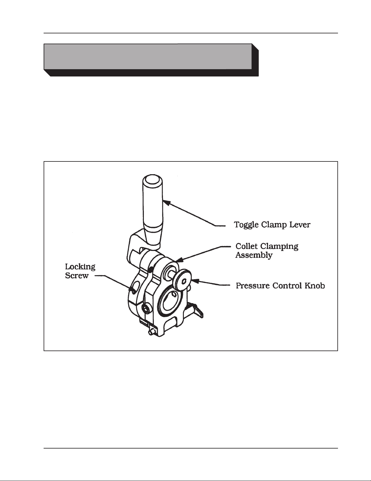
Locations of Various Items
INSTALLING THE QL KIT ONTO THE MODEL 301
Screw the QL Collet Clamping Assy onto the end of the Model 301 Tube Squaring
Machine until one thread of the Model 301 protrudes from the opposite end of the
Collet Clamping Assembly.
Tighten the Locking Screw to secure the QL Clamp Kit onto the front of the Model
301.
92-0630 Rev. 130308
21
Page 22
TRI TOOL INC.
CUTTING SPEEDS AND FEEDS
CUTTING SPEEDS
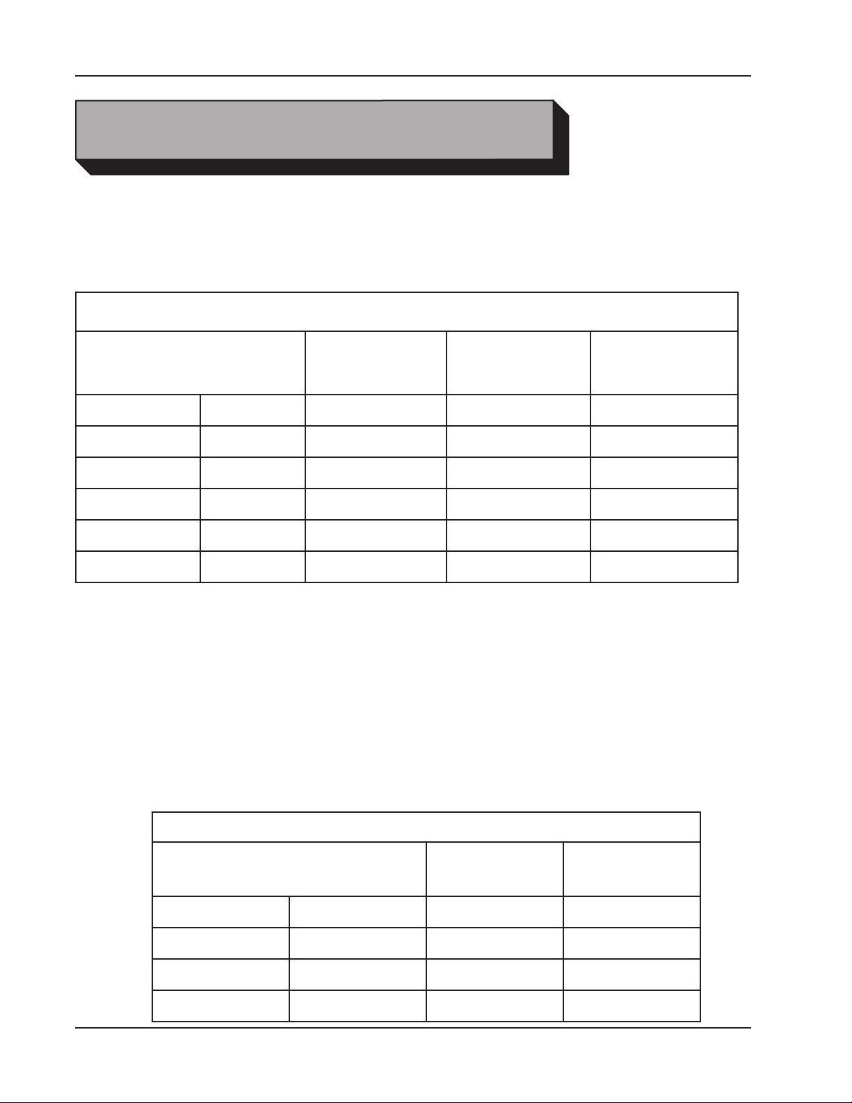
The chart below shows RPM required to obtain a specied Tool Bit cutting speed on
the surface of a pipe or tube.
Cutting Speeds
"Outside Diameter
of the pipe or tube"
.13" 3.2 mm 509 637 764
.25" 6.4 mm 255 318 382
.38" 9.5 mm 239 209 251
.50" 12.7 mm 127 159 191
.75" 19.1 mm 85 106 127
1.00" 25.4 mm 64 80 86
Use 200 surface inches per minute (508 surface centimeters per minute) for:
Stainless steels in general when no coolant is allowed, all heavy-wall tube and some
of the chrome/molybdenum steels.
Use 250 surface inches per minute (635 surface centimeters per minute) for:
Mild steels and some thin wall stainless steels when coolants are permitted and
applied.
RPM for 200 in/min
(508 cm/min)
RPM for 250 in/min
(635 cm/min)
RPM for 300 in/min
(762 cm/min)
Use 300 surface inches per minute (762 surface centimeters per minute) for:
Aluminum and thin-wall mild steel and tube with coolants.
Cutting Speeds for Tube Squaring
"Outside Diameter
of the pipe or tube"
.25" 6.4 mm 30 to 60 1 to 2 seconds
.50" 12.7 mm 20 to 40 1.5 to 3 seconds
.75" 19.1 mm 15 to 30 2 to 4 seconds
1.00" 25.4 mm 15 to 25 2.4 to 4 seconds
22
RPM
Range
Time per
Head Revolution
92-0630 Rev. 130308
Page 23

Model 301 Tube Squaring Machine
CUTTING FEEDS
Use very light feed for initial beveling or until a continuous cut is established.
This is very important for longer Tool Bit life when cutting through ame cut or
out-of-round pipe ends.
Use adequate feed, .003” to .006” (.08 mm to .15 mm) per revolution thereafter to
establish a continuous chip cut.
If the feed is too light, only light stringer chips will be removed.
If the feed is too heavy, the drive will start to overload and the chip will start to have
a rough edge or rough appearance.
Stainless steel, which work hardens, must be worked with a heavy enough feed to
stay under the work hardened surface [.003” to .006”(.08 mm to .15 mm) feed].
Never allow the tool bit to burnish the surface.
Reduced feeds and speeds will normally minimize chatter problems.
92-0630 Rev. 130308
23
Page 24
TRI TOOL INC.
Pipe Size
COLLETS
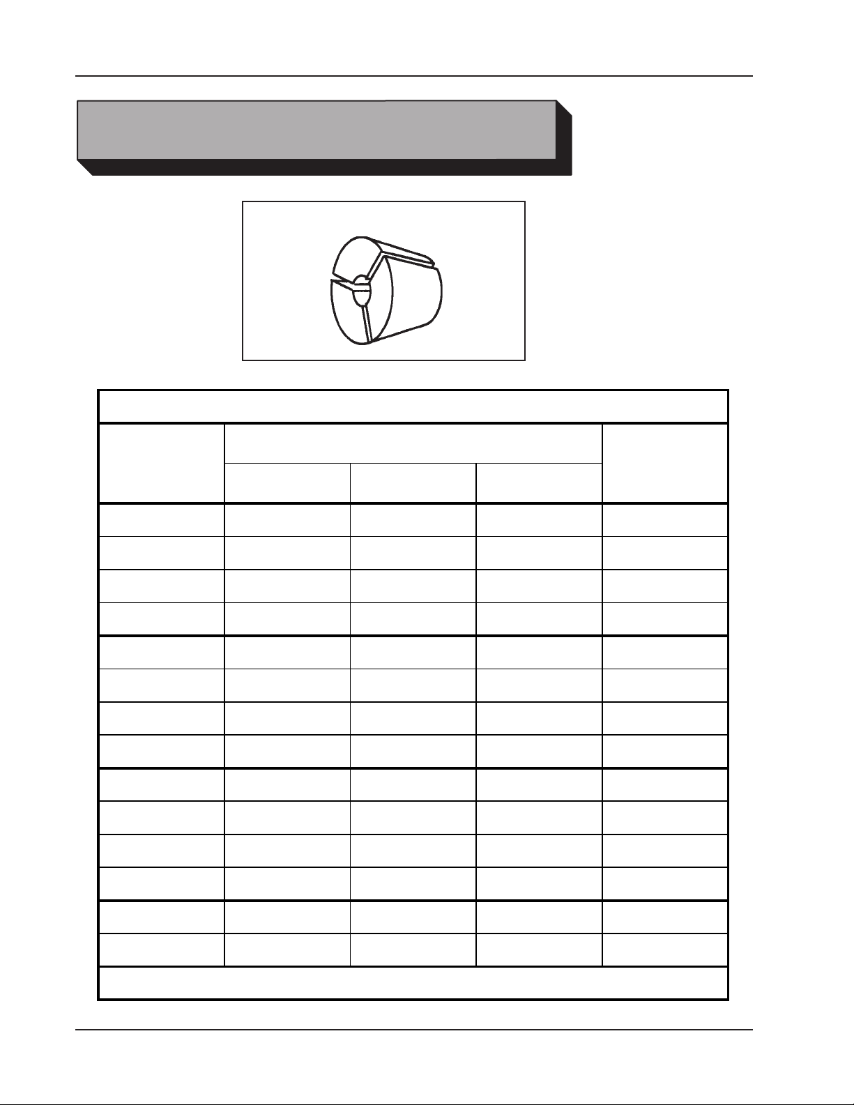
100 Series Collets
100 Series Collets
Diameter
Collet P/N
Fraction Decimal Metric
1/8" .125" 3.18 mm 30-2083
3/16" .188" 4.76 mm 30-2086
.236" 6.00 mm 30-2090
1/4" .250" 6.35 mm 30-1819
.276" 7.00 mm 30-1820
9/32" .281" 7.14 mm 30-1821
5/16" .313" 7.95 mm 30-1822
.315" 8.00 mm 30-1823
11/32" .344" 8.74 mm 30-1824
.354" 9.00 mm 30-1825
23/64" .359" 9.13 mm 30-1826
3/8" .375" 9.53 mm 30-1827
.394" 10.00 mm 30-1828
24
.400" 10.16 mm 30-1829
Contact TRI TOOL Inc. for sizes not listed
92-0630 Rev. 130308
Page 25

Model 301 Tube Squaring Machine
Fraction Decimal Metric
1/8" 13/32" .406" 10.31 mm 30-1830
.413" 10.50 mm 30-1831
27/64" .422" 10.72 mm 30-1832
.433" 11.00 mm 30-1833
7/16" .438" 11.13 mm 30-1834
15/32" .469" 11.91 mm 30-1835
.472" 12.00 mm 30-1836
1/2" .500" 12.70 mm 30-1837
.512" 13.00 mm 30-1838
17/32" .531" 13.50 mm 30-1839
1/4" .540" 13.72 mm 30-1840
.543" 13.80 mm 30-1841
35/64" .547" 13.89 mm 30-1842
.551" 14.00 mm 30-1843
9/16" .563" 14.30 mm 30-1844
.591" 15.00 mm 30-1845
19/32" .594" 15.08 mm 30-1846
.602" 15.29 mm 30-1847
5/8" .625" 15.88 mm 30-1848
.630" 16.00 mm 30-1849
41/64" .641" 16.27 mm 30-1850
21/32" .656" 16.66 mm 30-1851
.669" 17.00 mm 30-1852
100 Series Collets, Continued
Pipe Size
Diameter
Collet P/N
Contact TRI TOOL Inc. for sizes not listed
92-0630 Rev. 130308
25
Page 26

TRI TOOL INC.
Fraction Decimal Metric
3/8" .675" 17.15 mm 30-1853
.677" 17.20 mm 30-1854
.681" 17.30 mm 30-1855
11/16" .688" 17.48 mm 30-1856
.709" 18.00 mm 30-1857
23/32" .718" 18.24 mm 30-1858
3/4" .750" 19.05 mm 30-1859
25/32" .781" 19.84 mm 30-1860
.787" 20.00 mm 30-1861
13/16" .813" 20.65 mm 30-1862
1/2" .840" 21.34 mm 30-1863
27/32" .844" 21.44 mm 30-1864
.854" 21.70 mm 30-1865
55/64" .859" 21.83 mm 30-1866
.866" 22.00 mm 30-1867
7/8" .875" 22.23 mm 30-1868
29/32" .906" 23.00 mm 30-1869
15/16" .938" 23.83 mm 30-1870
31/32" .969" 24.61 mm 30-1871
63/64" .984" 25.00 mm 30-1872
1" 1.000" 25.40 mm 30-1873
3/4" 1.050" 26.67 mm 30-1874
1 1/16" 1.063" 27.00 mm 30-1875
100 Series Collets, Continued
Pipe Size
Diameter
Collet P/N
Contact TRI TOOL Inc. for sizes not listed
26
92-0630 Rev. 130308
Page 27
Model 301 Tube Squaring Machine
Fraction Decimal Metric
1.071" 27.20 mm 30-1876
1.102" 28.00 mm 30-1877
Replacement Spring (P/N 40-0229) 3 each required per Collet.
Replacement O-Rings (P/N 28-0252 and P/N 28-0253) 1 each required per
Collet.
Contact TRI TOOL Inc. for sizes not listed
100 Series Collets, Continued
Pipe Size
Diameter
Collet P/N
92-0630 Rev. 130308
27
Page 28
TRI TOOL INC.
DURABIT 1
99-1331*
DURABIT 2
99-1529
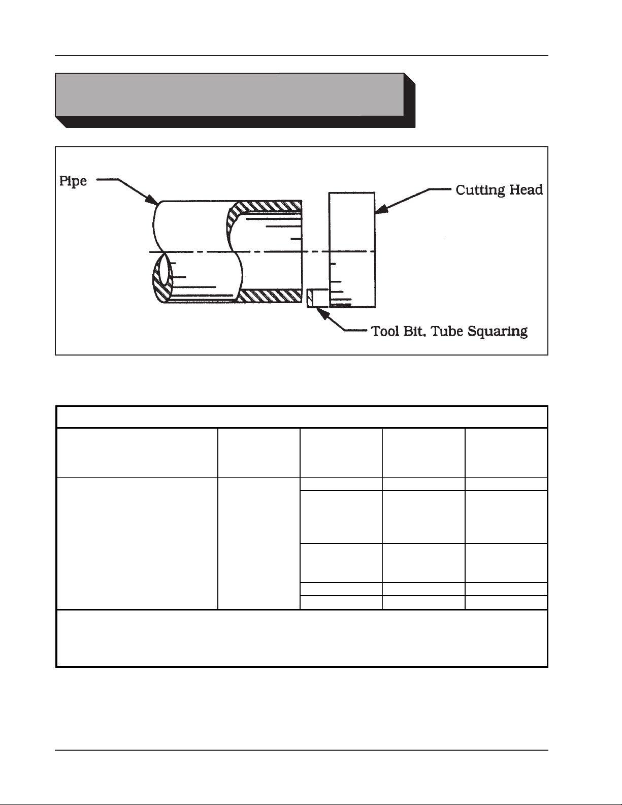
Tube Squaring Tool Bit
TOOL BITS
Tube Squaring Tool Bits
Range
*M42
Note: Use the .969" high Tool Bits for 1/8" to 1/4" dia tubing, also for wall thickness
of .030" or less, these Tool Bits cut closer to the Collet face for less tube flexing
during cutting.
Max. Wall
Thickness
.125".125" OD thru 1.05" OD
Pipe or Tube
Material
CS .750" 99-1480
SS .750"
SS .969"
Inconel .750" 99-3650*
Incolly .969" 99-3834*
Tool Bit
Height
Squaring
Tool Bit P/N
99-1445
99-1506
99-2448
28
92-0630 Rev. 130308
Page 29
Beveling Tool Bit
Range
Max. Wall
Thickness
Pipe or Tube
Material
37.5 Degree
Angle
Beveling
Tool Bit P/N
CS 99-1382
SS 99-1219
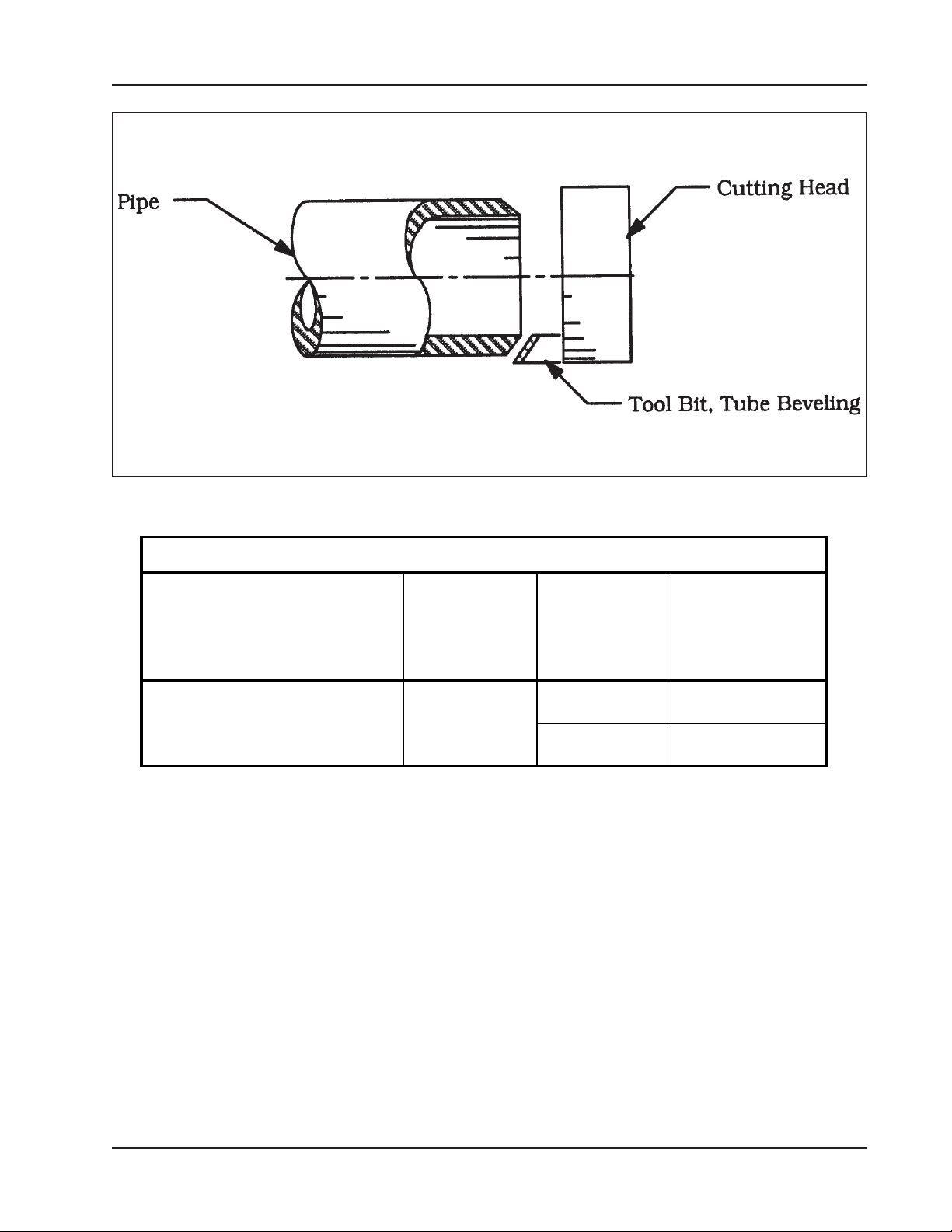
Beveling Tool Bits
Pipe: 1/2" thru 3/4"
Tube: .625" thru 1.05" (OD's)
sch 40
.125"
Model 301 Tube Squaring Machine
92-0630 Rev. 130308
29
Page 30

TRI TOOL INC.
TROUBLE SHOOTING
Problem: The Tool Bit Chatters
Probable causes:
The tool bit is loose or overextended.
The tool bit is damaged.
The tool holder is too loose in the slides.
The cutting speed is too fast.
The clamping pads are loose on the pipe or tube.
Cutting uid is required.
The main bearing pre-load is loose.
Problem: There is excessive Tool Bit wear
Probable causes:
The pipe or tube material is too hard or abrasive.
The cutting speed is too fast.
Cutting uid is required.
A dull Tool Bit is causing surface hardening conditions (Stainless pipe or
tubing).
There is scale or other foreign matter on the pipe or tube, which is dulling
the tool bit at the start of the cut.
The tool bit is incorrect for the material being cut.
Problem: Thesurfacenishisrough
Probable causes:
The tool bit is dull, chipped, etc.
Metal build-up on the cutting edge of the tool bit is creating a false cutting
edge.
Cutting uid is required.
The cutting speed is incorrect.
Problem: The tool holder is not feeding
Probable causes:
The feed pin is broken or out of position.
The feed sprocket shear pin is broken.
The feed screw is stripped.
The feed nut is stripped.
The slide rails are too tight.
30
92-0630 Rev. 130308
Page 31

Model 301 Tube Squaring Machine
Problem: There is a loss of air power
Probable causes:
The air supply pressure is too low.
The air lter is plugged.
The air line size is insufcient.
The air line is too long.
Problem: There is a loss of hydraulic power
Probable causes:
The hydraulic supply pressure is too low.
The hydraulic lter is plugged.
The hydraulic line size is insufcient.
The hydraulic line is too long.
Problem: The tool bit will not reach the work
Probable causes:
Incorrect tool blocks are installed for the size of the pipe or tube being
worked on.
Incorrect tool bit is installed.
Problem: The hydraulic motor will not start
Probable causes:
The hydraulic power supply is shut off.
The hydraulic motor is damaged and will not run free.
92-0630 Rev. 130308
31
Page 32

TRI TOOL INC.
ACCESSORIES
The following accessories are recommended for use with the Model 301 Tube
Facing Machine and are available from TRI TOOL INC.
1. A portable Air Filter Caddy (P/N 75-0100).
A FRL is required to protect the warranty and tool on all Tri Tool air driven
tools.
2. An Pneumatic Foot Pedal
3. An Electric Foot Pedal
4. A Bench Top Stand (P/N 60-0022)
5. Collets (Refer to the section ‘Collets’)
6. Tool Bits (Refer to the section ‘Tool Bits’)
32
92-0630 Rev. 130308
Page 33
Model 301 Tube Squaring Machine
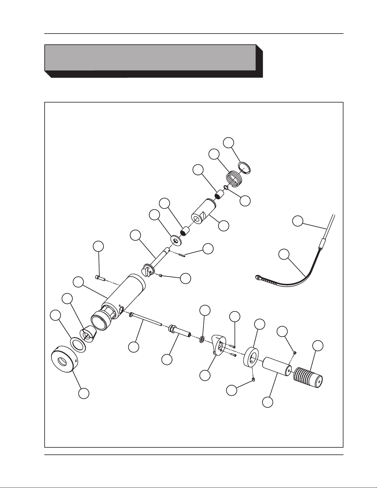
ILLUSTRATED PARTS BREAKDOWN
MODEL 301 TUBE SQUARING MACHINE
6
12
4
21
17
4
10
15
3
20
2
1
14
9
8
11
19
5
16
18
22
24
9
7
23
92-0630 Rev. 130308
25
13
33
Page 34

TRI TOOL INC.
Parts List, Model 301
Item Part
No. No. Description Qty
03-0010 HEAD ASSY, BEVELING
1. 14-0006 SHAFT ASSY 1
2. 19-0011 HOUSING 1
3. 20-0016 SHAFT ASSY 1
4. 29-0028 BEARING, ROLLER 2
5. 30-0062 RING, RETAINING, EXTERNAL 1
6. 30-0063 RING, RETAINING, EXTERNAL 1
7. 30-2278 HANDLE, GRIP 1
8. 32-0026 PIN, ROLL, 1/8 DIA. X 3/4" 1
9. 33-0499 SCREW, SET, 1/4-20 X 1/4", CUP PT 3
10. 34-0059 WASHER, FLAT, DELRIN 1
11. 34-0060 WASHER, FLAT, DELRIN 1
12. 40-0035 SPRING, COMPRESSION 1
13. 41-0018 HANDLE, GRIP 1
14. 46-0014 SLEEVE 1
15. 46-0016 SLEEVE 1
16. 23-0023 ROD 1
17. COLLET, 100 SERIES (SEE COLLET SECTION) REF
18. 30-0873 HOLDER, FLEX RUBBER KEY 1
19. 27-0614 ADAPTER, INDICATOR 1
20. 33-0041 SCREW, CAP, 1/4-20 X 7/8" 1
21. 34-0232 WASHER, THRUST 1
22. 33-0013 SCREW, CAP, #6-32 X 1/2" 2
23. 35-0411 NUT, COLLET 1
24. 46-0480 SLEEVE, INDICATOR 1
25. 33-0501 SCREW, SET, 1/4-20 X 3/8", CUP PT 1
NOT SHOWN:
05-1003 SHIPPING KIT 1
36-0008 WRENCH, L, 3/16", HEX 1
36-0010 WRENCH, L, 1/4", HEX 1
36-0018 WRENCH, T, 1/8", HEX 1
86-0048 CARRYING CASE, ELECTRIC REF
86-0070 CARRYING CASE, AIR REF
34
92-0630 Rev. 130308
Page 35
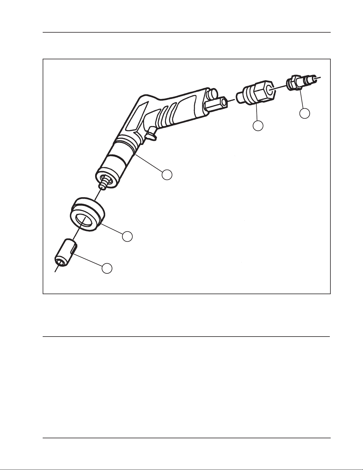
Model 301 Tube Squaring Machine
AIR MOTOR ASSEMBLY
5
2
1
4
3
Parts List, Motor Assy, Air
Item Part
No. No. Description Qty
1. 53-0045 VALVE, FLOW CONTROL 1
2. 54-0149 COUPLING, MALE, QD 1
57-0199 MOTOR ASSY, AIR 1
3. 27-0019 ADAPTER 1
4. 46-0377 SLEEVE 1
5. 57-0198 MOTOR, AIR 1
92-0630 Rev. 130308
35
Page 36
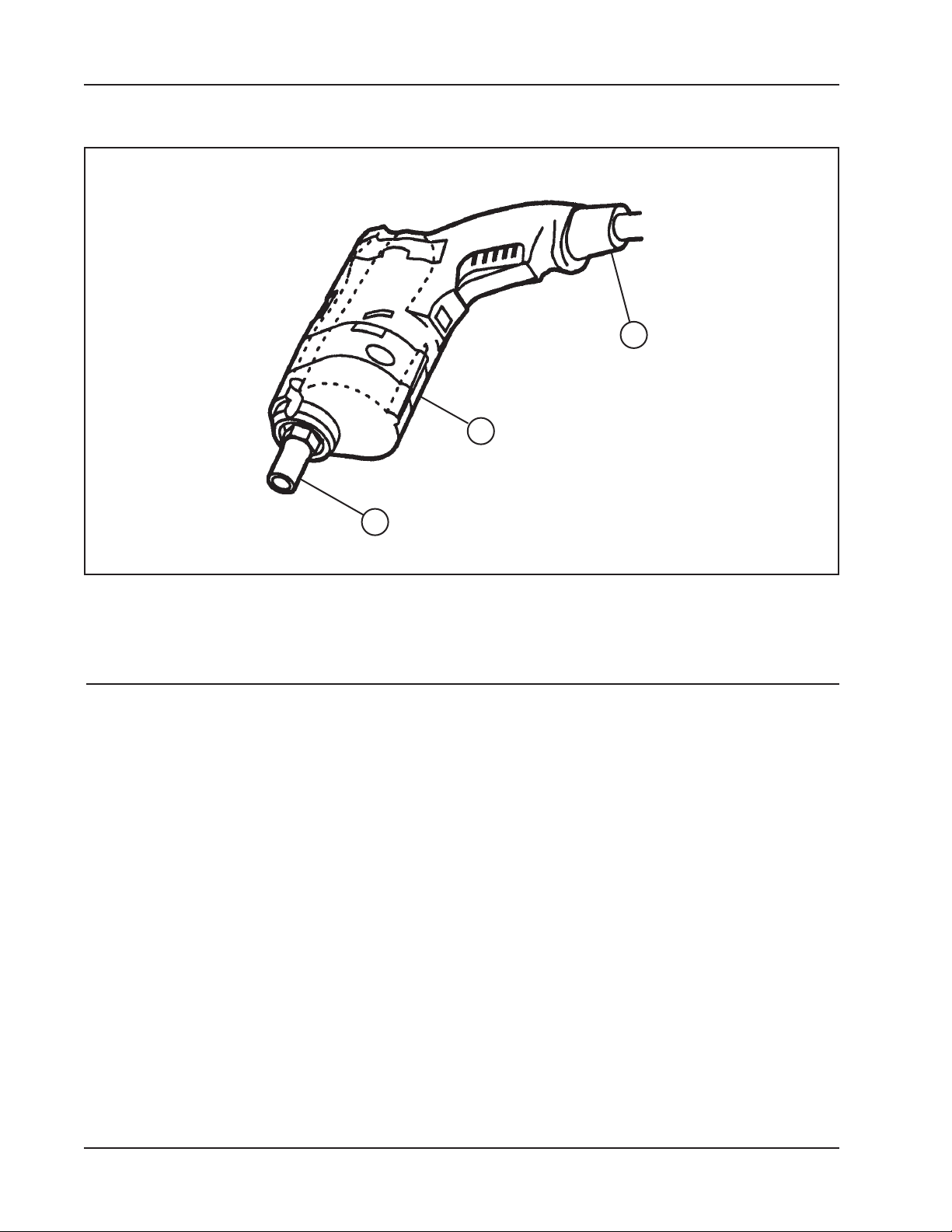
TRI TOOL INC.
ELECTRIC MOTOR ASSEMBLY
3
2
1
Parts List, Motor Assy, Electric
Item Part
No. No. Description Qty
58-0004 MOTOR ASSY, ELECTRIC, 110 VAC 1
1. 27-0018 ADAPTER 1
3. 58-0003 MOTOR, ELECTRIC, 110 VAC (Milwaukee) 1
MOTOR ASSY, ELECTRIC, 110 VAC (Bosch) 1
1. 27-0018 ADAPTER 1
2. 27-0060 ADAPTER 1
3. 58-0038 MOTOR, ELECTRIC, 110 VAC (Bosch) 1
MOTOR ASSY, ELECTRIC, 220 VAC (Bosch) 1
1. 27-0018 ADAPTER 1
2. 27-0060 ADAPTER 1
3. 58-0039 MOTOR, ELECTRIC, 220 VAC (Bosch) 1
36
92-0630 Rev. 130308
Page 37
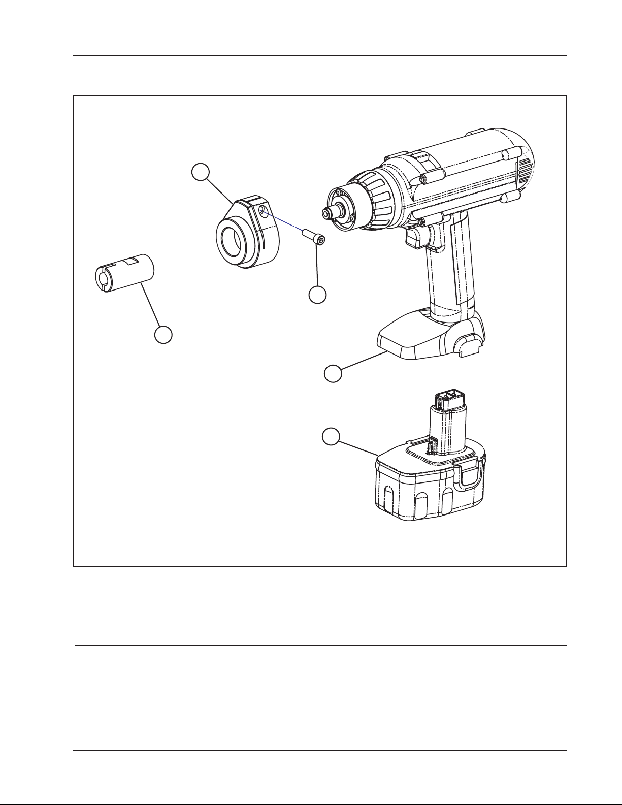
Model 301 Tube Squaring Machine
BATTERY POWERED, 14.4V, DRIVE KIT
1
3
2
4
5
Parts List, Drive Kit, Battery Powered, 14.4V (P/N 58-0260)
Item Part
No. No. Description Qty
1. 19-1425 HOUSING, FRONT 1
2. 27-1315 ADAPTER 1
3. 33-0040 SCREW, CAP, 1/4-20 X 3/4" 1
4. 58-0259 MOTOR, CORDLESS, 14.4 VOLT 1
5. 30-2350 BATTERY, 14.4v (Dewalt) 1
92-0630 Rev. 130308
37
Page 38
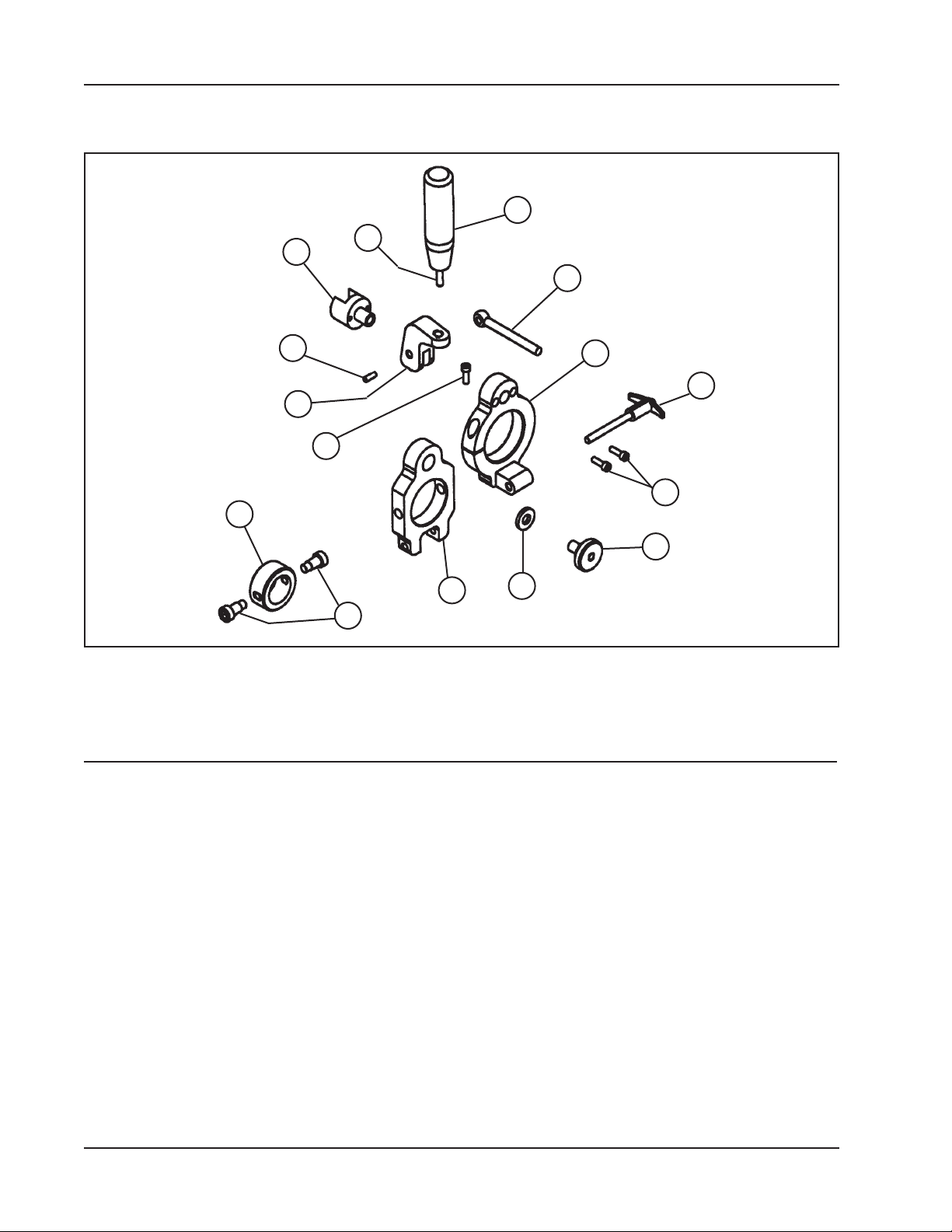
TRI TOOL INC.
COLLET QUICK LOCK SYSTEM FOR THE MODEL 301
11
1
4
15
2
7
9
13
6
12
14
8
10
Parts List, Collet Quick Lock System for the Model 301 (05-0240)
3
5
Item Part
No. No. Description Qty
1. 20-0629 SHAFT 1
2. 27-0534 ADAPTER 1
3. 32-0089 PIN, BALL LOCK, T-HANDLE 1
4. 32-0140 PIN, DOWEL, 1/4 DIA X 3/4" 1
5. 33-0029 SCREW, CAP, #10-24 X 5/8", ZP 2
6. 33-0040 SCREW, CAP, 1/4-20 X 3/4", ZP 1
7. 33-0533 SCREW, SET, 3/8-16 X 1", CUP PT 1
8. 33-1961 SCREW, SHOULDER 2
9. 33-1962 BOLT, EYE 1
10. 34-0134 WASHER, SELF ALIGNING 1
11. 41-0125 HANDLE 1
12. 42-0162 KNOB 1
13. 47-1095 BRACKET 1
14. 47-1083 BRACKET, HINGE 1
15. 62-0103 CAM 1
38
92-0630 Rev. 130308
Page 39
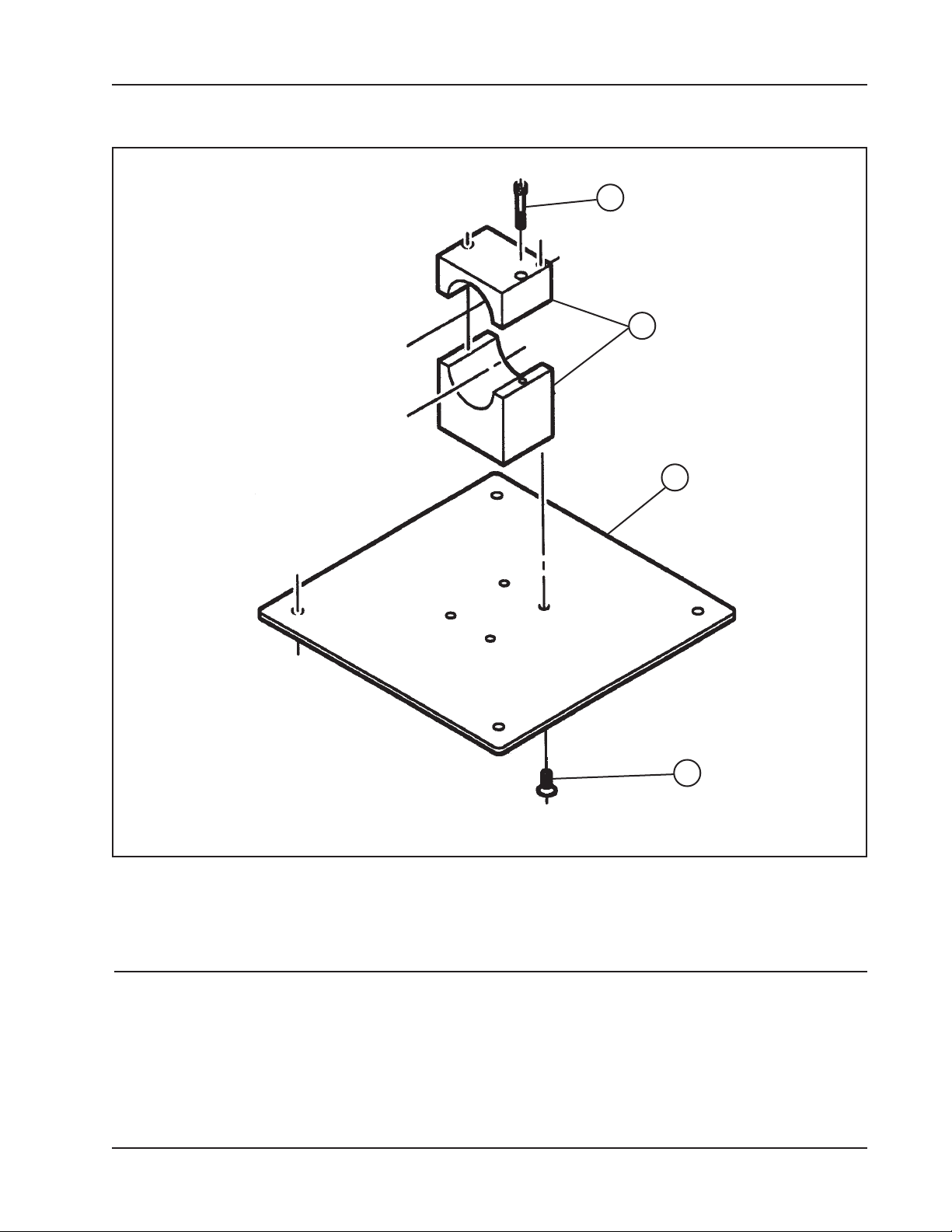
Model 301 Tube Squaring Machine
BASE STAND ASSEMBLY
2
4
1
3
Parts List, Stand Assy, Base (P/N 60-0022)
Item Part
No. No. Description Qty
1. 24-0326 PLATE, BASE 1
2. 33-0045 SCREW, CAP, 1/4-20 X 1 3/4", ZP 2
3. 33-0369 SCREW, FLAT, 5/16-18 X 3/4" 4
4. 48-0173 BLOCK, RETAINING 1
92-0630 Rev. 130308
39
Page 40

TRI TOOL INC.
DEWALT SAFETY INSTRUCTIONS
The DeWALT Cordless Drill/Driver comes with an 'Instruction Manual' and should be
referenced for all safety and operating procedures.
40
92-0630 Rev. 130308
 Loading...