

Page 1
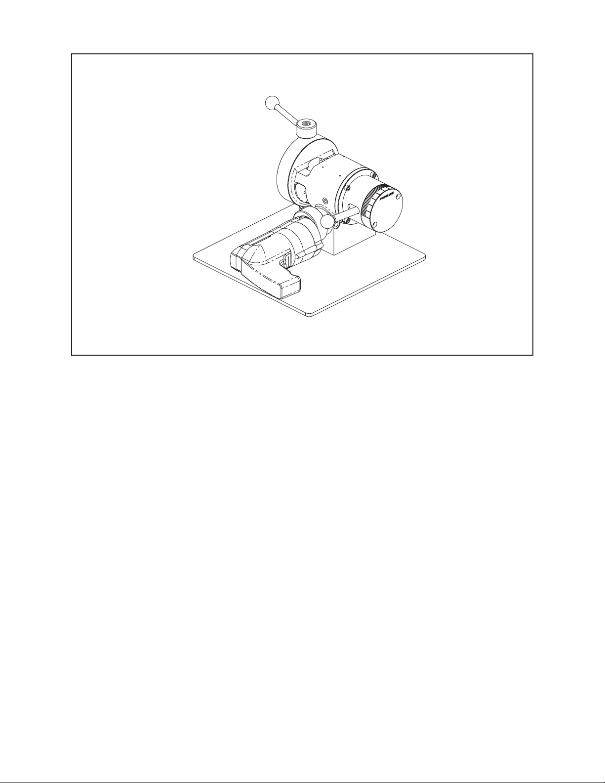
TABLE OF CONTENTS
CUSTOMER MESSAGE Inside Front Cover
SAFETY PRECAUTIONS 3
92-0547 Rev. 140610
Model 302 Tube Squaring Machine
GENERAL 6
SPECIFICATIONS 7
MAINTENANCE 9
OPERATION 11
CUTTING SPEEDS AND FEEDS 19
SADDLE SETS 20
TOOL BITS 21
TROUBLESHOOTING 23
ILLUSTRATED PARTS BREAKDOWN 25
TOOL BIT RESHARPENING POLICY Inside Back Cover
WARRANTY INFORMATION Inside Back Cover
Page 2

Copyright 2014
Proprietary property of TRI TOOL Inc.
No reproduction, use, or duplication of the information
shown hereon is permitted without the express written
consent of TRI TOOL Inc.
Page 3

SAFETY PRECAUTIONS
IN GENERAL
When using rotating head cutting equipment, basic safety precautions should always
be followed to reduce the risk of personal injury.
Operate this tool only in accordance with specic operating instructions.
Do not override the deadman switch on the power unit. Locking down, ob-
WARNING:
DRESS CONSIDERATIONS
structing, or in any way defeating the deadman switch on the power drive unit
may result in serious injury.
Model 302 Tube Squaring Machine
Use standard safety equipment. Hard hats, safety shoes, safety harnesses, protective clothes, and other safety devices should always be used when appropriate.
Use safety glasses. Do not operate cutting tools without eye protection.
Dress properly. Do not wear loose clothing or jewelry. They can be caught in rotat-
ing and moving parts. Avoid slippery oors or wear nonskid footwear. If you have
long hair, wear protective hair covering to contain it.
WORK AREA
Keep the work area clean. Keep the area well lit. Keep electrical cords, cables, rags,
rigging straps, and etc. clear of rotating equipment. Do not use power-cutting tools
in the presence of ammable liquids and gasses.
Keep visitors away. Do not let visitors or untrained personnel at or near operating
tools. Enforce eye protection requirements for all observers.
Do not over reach. Keep proper footing at all times.
Stay alert. Watch what you are doing. Use common sense. Do not operate tools
when you are tired.
92-0547 : Rev. 140610
3
Page 4

TRI TOOL INC.
TOOL CARE
Maintain tools with care. Keep tools in good operating condition. Sharp tool bits
perform better and safer than dull tool bits. Well maintained tools function properly
when needed.
Check for damaged parts. If a tool has malfunctioned, been dropped or hit, it must
be checked for damage. Run no-load tests and feed function checks. Do a complete visual inspection.
Electric motors. Use only with proper AC voltage power sources and observe all
normal electric shock hazard procedures.
Do not abuse power and control cords. Pulling or running over cords and cables can
result in electrical shock hazards and malfunctions. Keep control and power cords
out of all cutting uids and water.
Hydraulic drives. Observe proper procedures for electrically driven power sources.
Avoid damage to hydraulic lines. Keep quick-disconnects clean. Grit contamination
causes malfunctions.
Air tools. Check the exhaust mufer. Broken or damaged mufers can restrict air
ow or cause excessive noise. Use air motors only with a ltered, lubricated and
regulated air supply. Dirty air, low-pressure air or over pressure air will cause malfunctions, including delayed starting.
AREA EQUIPMENT
Secure work. Whenever possible use clamps, vises, chains and straps to secure
pipe.
Make sure the tool is secured; it is safer to have both hands free to operate the tool.
TOOL USE
Use the right tool and tool bit for the job. Do not use a tool, which is incorrect for the
job you are doing.
Keep the tool bits fully engaged in the tool bit holders. Loose bits are a safety
hazard.
4
92-0547 : Rev. 140610
Page 5

Model 302 Tube Squaring Machine
Disconnect power supply during setup and maintenance. Use all ‘Stop’ or Shut off’
features available when changing or adjusting tool bits, maintaining the tool, or when
the tool is not in use.
Remove adjusting keys and wrenches before applying power to the equipment. Develop a habit of checking the tool before turning it on to make sure that all keys and
wrenches have been removed.
Do not force tools. Tools and tool bits function better and safer when used at the
feed and speed rate for which they were designed.
Do not reach into rotating equipment. Do not reach into the rotating head stock to
clear chips, to make adjustments, or to check surface nish. A machine designed to
cut steel will not stop for a hand or an arm.
Handle chips with care. Chips have very sharp edges and are hot. Do not try to pull
chips apart with are hands; they are very tough.
Avoid unintentional starts. Do not carry or handle tools with your hand on the operating switches or levers. Do not lay the tool down in a manner that will start the
drive. Do not allow the tool to ip around or move when adjusting or changing tool
bits.
Store idle tools properly. Disconnect tools from the power source and store in a safe
place. Remove tool bits for safe handling of the tool.
92-0547 : Rev. 140610
5
Page 6

TRI TOOL INC.
The Model 302 Tube Squaring Tool is a bench mounted machine designed specifically to prepare tubes for autogenous welding. The 302 will face (square) .188” to
2.375” (4.8 mm to 60.3 mm) outside diameter tubing with a wall thickness up to .200”
(5.1 mm). The 302 uses an OD Saddle Clamping System for holding and rounding
the tube. The 302 accepts its own torque through the Saddle Clamping System.
The standard Saddle Clamping System requires a straight length of tube .875” (22.2
mm) long. Automatic clamping can be provided using a pneumatic clamping system.
Speed control is provided with a variable speed electric drive or a pneumatic drive
motor. Feed is provided by a lever action for excellent feed control. A microfeed system provides an accurate controlled feed alternative.
GENERAL
6
92-0547 : Rev. 140610
Page 7
SPECIFICATIONS
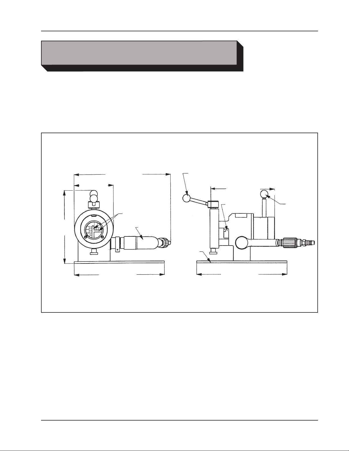
Model 302A with an Air Motor (P/N 01-1271)
Weight: 18.5 lbs (8.4 kg) without saddles
Power Requirements: 26 cfm at 90 PSI (12 L/s at 621 kPa)
Envelope Drawing with Air Motor
Model 302 Tube Squaring Machine
9.57"
(243.1mm)
12.80" (325.1mm)
5.20" (132.1mm)
12.00" (304.8mm)
TOOL BIT SLOTS
AIR MOTOR
CLAMP HANDLE
BASE
PLATE
8.57" (217.7mm)
CUTTER
HEAD
12.00" (304.8mm)
FEED
HANDLE
92-0547 : Rev. 140610
7
Page 8
TRI TOOL INC.
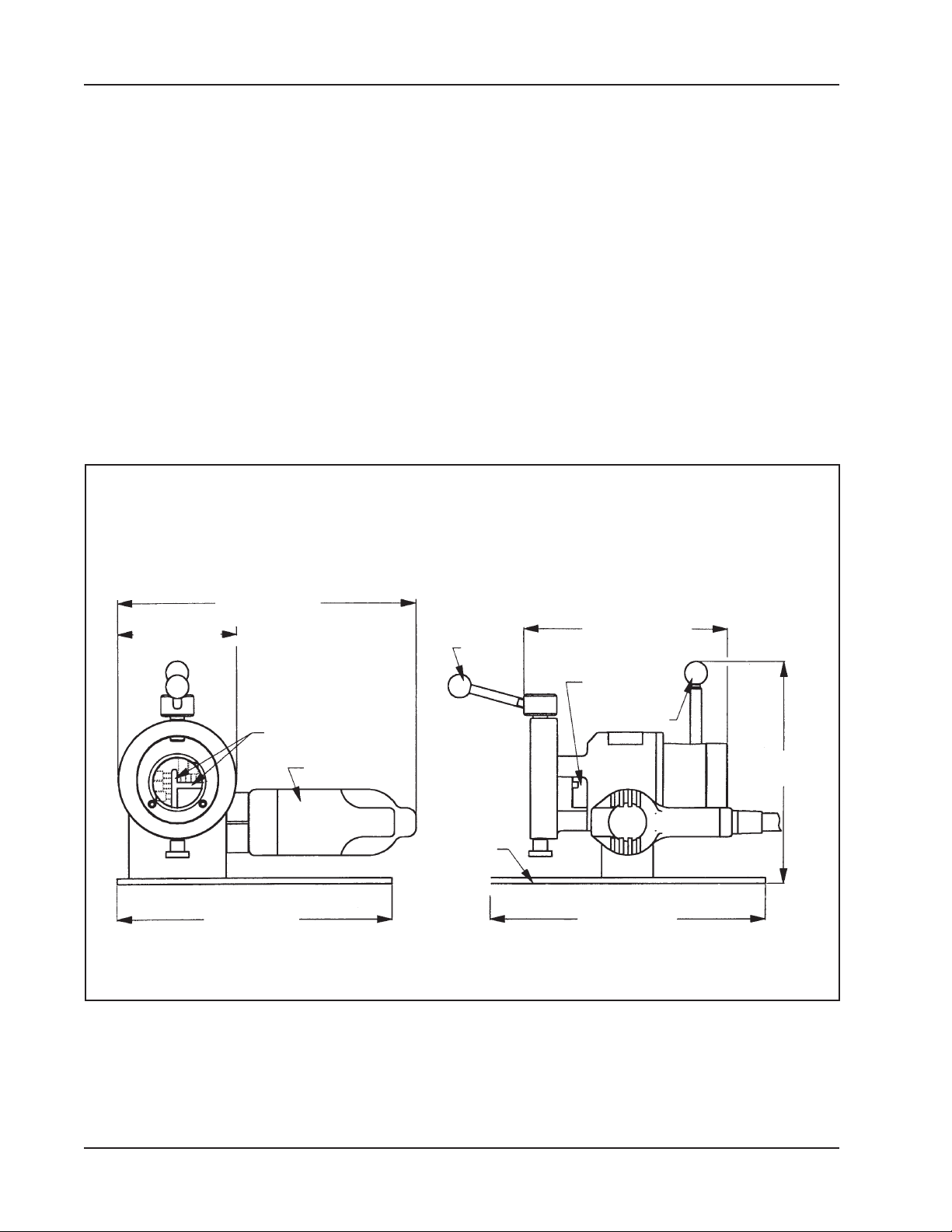
Model 302E with a 110 VAC, 60 Hz Electric Motor (P/N 01-1242)
Weight: 20.6 lbs (9.3 kg) without saddles
Power Requirements: 110 VAC, 50/60 hz, 7.0 amp
Model 302E with a 220 VAC, 50 Hz electric motor (P/N 01-1770)
Weight: 20.6 lbs (9.3 kg) without saddles
Power Requirements: 220 VAC, 50/60 hz, 4.0 amp
Envelope Drawing with Electric Motor
15.00" (381.0mm)
5.20" (132.1mm)
12.00" (304.8mm)
TOOL BIT SLOTS
ELECTRIC
MOTOR
CLAMP
HANDLE
BASE
PLATE
8.57" (217.7mm)
CUTTER HEAD
FEED
HANDLE
9.57"
(243.1mm)
12.00" (304.8mm)
8
92-0547 : Rev. 140610
Page 9
Model 302 Tube Squaring Machine
MAINTENANCE
All components should be cleaned and coated with a light lm of oil prior to use.
Use a clean, non-detergent oil, preferably SAE 10 (90 SSU) or lighter.
The air supply for the Model 302A with an air motor should include an adequate lter,
regulator and lubricator (FRL).
NOTE:
If the Model 302 is operated in the vertical position (cutting head up), turn it upside
down and remove the chips and/other debris after each bevel has been completed.
WARNING:
Bearing and gears are to be lubricated using a high string utility grease (P/N 68-
0020).
The Motor Warranty is void if damage occurs from contaminated air or lack of
lubrication.
Tool life may be severely shortened, unless chips and/or debris, that have
been deposited on the cutting head during the machining operation, are removed.
AIR MOTOR LUBRICATION
Disassembly of a power unit voids warranty, except when performed by a
WARNING:
No direct maintenance is normally required on the Air Motor.
TRI TOOL designated repair technician. (Letter of designation is required.)
However, the air supply must ow through a lter/regulator/lubricator (FRL) unit or
separate units before arriving at the air motor.
The FRL unit must be maintained as required (frequency dependent on the basic air
supply) to keep the water trap drained, lter cleaned and the lubricator oil reservoir
lled so that a drop of oil every two (2) to ve (5) seconds is owing.
If the Model 302A is to be left idle for 24 hours or more after being run on ‘wet’ air, it
is advisable to squirt oil directly into the air motor inlet and run the motor for two (2)
to three (3) seconds.
This will prevent rusting and ‘freezing’ of the rotor vanes.
92-0547 : Rev. 140610
9
Page 10

TRI TOOL INC.
Lubricant Recommendations:
The air motor requires a ‘Class 2’ lubricant, viscosity of 100 to 200 SSU at
100° F (38° C).
• TRI TOOL Inc. – Air Tool Lubricant (P/N 68-0022)
• AMOCO – American Industrial Oil No. 32
• Atlantic Richeld – Duro Oil S-150
• Chevron – A.W. Machine Oil 32
• Exxon – Nuto H32
• Shell – Tellus Oil 32
NOTE:
The bearings in either the air motor or the electric motor are sealed and do
not require any lubrication.
10
92-0547 : Rev. 140610
Page 11
GENERAL
The handle of the motor may be rotated to another position as necessary to t into
some situations.
Loosen the cap screw in the clamp bracket and rotate the motor handle to the desired position.
Tighten the cap screw before turning the motor on.
Select the Tool Bit required to machine the tube ends square and at as required for
an autogenous weld joint.
Model 302 Tube Squaring Machine
OPERATION
WARNING:
General Guide Lines for Selecting a Tool Bit
NOTE:
The use of dull or improperly designed Tool Bits or Tool Bits not manufactured
by Tri Tool Inc. may result in poor performance and may constitute abuse of
this machine and therefore void the Tri Tool Inc. factory warranty.
Selection of the Tool Bit should be based on tubing material, the tubing size,
and how critical is it to have a near burr free end. The DURABIT 1, DURABIT
2 and DURABIT 3 Tool bits provide near burr free ends (measured burrs less
than 0.004" or 0.1mm) on most materials.
The DURABIT 1, DURABIT 2 and DURABIT 3 were developed for optimum
burr conditions on electropolished austenitic Stainless Steel tubing such as
316L and to run at higher speeds than other tube squaring tool bits. Electropolished stainless steels have a micro-thin surface on the ID, which is high in
Cr and Ni. This surface is soft, but tough and difcult to cut without a burr.
The Part Number for a DURABIT 1 is “DURBIT1”, DURABIT 2 is “DURBIT2”
and DURABIT 3 is “DURBIT3”.
For carbon steel tube with a wall thickness greater than 0.083" (2.24mm).
Contact your Tri Tool representative for Tool Bit recommendations.
M-42 Tool Bits are available for use with the exotic alloys where the high heat
resistance is required to avoid burning the cutting edge of the Tool Bit. Call
your Tri Tool representative for recommendations.
92-0547 : Rev. 140610
11
Page 12
TRI TOOL INC.
M-42 can improve the life expectancy of the Tool Bit under some conditions
but it should be noted that M-42 Tool Bits are more brittle than the M-2 Tool
Bits. Therefore, there is a much greater risk of damaging the Tool Bit when
installing the tubing in the Tube Squaring Machine. Loss of Tool Bits from
damaged edges may not offset the improved cutting life expected from M-42
tool steel.
Tool Bits made from M-42 tool steel with its high heat resistance, may provide
longer life on some exotic alloys. Be aware that the cutting speeds to obtain a
burr FREE end is slower for all tool bits other than the DURABIT Series Bits.
The cost impact of the slower running speeds may not offset the increase in
life expectancy.
Select the tool bit(s) required to machine the end conguration desired.
When performing a tube squaring operation the tool bit may be placed in any
slot.
When performing separate machining operations such as facing or beveling,
the tool bit(s) may be installed in any one of the two cutting head slots.
When performing two machining operations such as facing and beveling, the
tool bits should be installed with one in each slot.
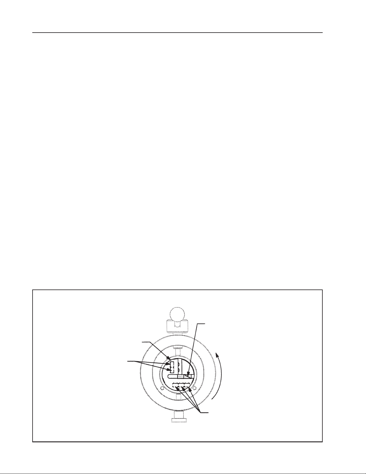
INSTALLING A TOOL BIT INTO THE TOOL
Tool Bit Installation
Cutting Head
Cap Screws
(Hidden)
Squaring Tool Bit, Cutting Edge
Rotation
12
Cap Screws
(Hidden)
92-0547 : Rev. 140610
Page 13
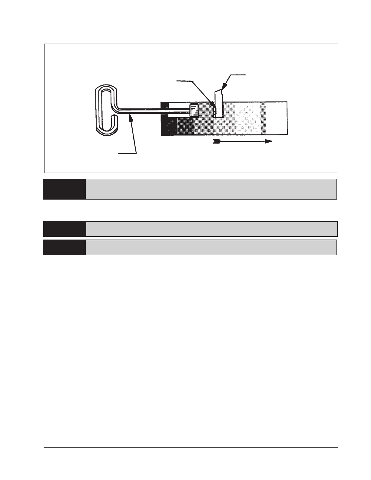
Securing the Tool Bit
Model 302 Tube Squaring Machine
Hex Wrench
CAUTION:
Insert the Tool Bit into the slot in the Cutting Head.
CAUTION:
NOTE:
Cap Screw
Cutting Edge
Rotation
Insure that the Model 302 Tube Squaring Machine is disconnected from the
power source before installing a Tool Bit.
The cutting edge of the Tool Bit must be located on the radial centerline.
Do NOT install the Tool Bit backwards.
Position the tip of the tool bit to be just inside the inside of the tube wall. The tip
must always be Inside of the tube bore to achieve a at end. The tip location is
critical on .50" to 1.00" tube because when tip is too close to the center of the tube
the chip may roll into the tube and scratch the ID.
Tighten the cap screws to secure the tool bit(s) to the cutting head.
CUTTING PROCEDURES
DURABIT 1 Tool Bit
The DURABIT 1 is designed to run at the maximum available RPM from the
tool which makes the cutting procedure different relative to the other Tube
Facing Bits with 99-xxxx part numbers.
Visually verify that the tool bit will clear the end of the tube with the feed fully
retracted (normal return position). A tube end that is cut at an angle (not
square) can be set such that the tool bit clears the end, but when the tool bit
is rotated it will engage the tube will a very heavy cut.
92-0547 : Rev. 140610
13
Page 14

TRI TOOL INC.
Using the maximum speed available from the motor, turn the machine on and
advance the tool bit into the end.
NOTE:
NOTE:
Be careful and not risk damage to the tool bit from an excessive cut.
On interrupted or out of square ends, advances the bit slowly with light feed
pressure (torque applied to the feed handle) until a continuous cut is achieved
(the tool bit is cutting all the way around the end).
Once a full cut is achieved use moderate feed pressure to nish the cut
(either to a just achieve a quality end or to cut to a scribe line).
When the desired length is achieved, let the machine make one or two
revolutions without feeding the machine (i.e. while holding the feed handle
in a xed position). If the feed backed out before the making the nish
revolutions the end will not be square. This effect will be most noticeable on
larger diameter tubes.
Back the tool bit away from the end with the machine running.
Never stop the machine with the tool bit in the cut as this can chip the tool bit
99-xxxx Series TUBE SQUARING Tool Bits
The 99-xxxx series tool bit achieves the best end results when run at slow
speed. This is especially true with electropolished tube. Electropolished
austenitic stainless steel tube alloys are very soft and tend to “mush” away
from the cutting edge. If the tube or the tool bit get warm, this tendency is
increased. Further, the cutting speed must be kept very slow to avoid heat at
the tool bit. If the tool bit to tube interface is allowed to get hot then it is like a
dull knife to cut warm butter. The material just ows away from the bit forming
large burrs. The DURABIT Series tool bits have a unique cutting edge design
and proprietary coating, which work best at high cutting speeds and are
the most commonly recommended tool bits for tube squaring application.
However, for some applications the 99 series tool bits still nd a home and the
following cutting procedures apply.
Visually verify that the tube bit will clear the end of the tube with the feed
fully retracted (normal return position). A tube end that is cut at an angle (not
square) can be set such that the tool bit clears the end, but when the tool bit
is rotated it will engage the tube will a very heavy cut.
Turn the machine on, and using the speed control of the motor, set the RPM
between 30 and 50 then advance the tool bit into the end. Use the low end
14
92-0547 : Rev. 140610
Page 15

Model 302 Tube Squaring Machine
of the speed range (30 RPM) for 0.50 and larger tube and the high end (50
RPM) of the range for smaller tube.
NOTE:
Be careful and not risk damage to the tool bit from an excessive cut.
On interrupted or out of square ends, advances the bit slowly with light feed
pressure (torque applied to the feed handle) until a continuous cut is achieved
(the tool bit is cutting all the way around the end). The operator must increase
the speed control position to maintain the cutting speed as the load increases.
Once a full cut is achieved use moderate feed pressure to nish the cut
(either to a just achieve a quality end or to cut to a scribe line). The operator
should strive to achieve a loose but continuous chip. The chip should be a
loose curl, not a tight spiral that looks like an ice cycle.
When the desired length is achieved, let the machine make one or two
revolutions without feeding the machine (i.e. while holding the feed handle
in a xed position). If the feed is backed out before making the nishing
revolutions the end will not be square. This effect will be most noticeable on
larger diameter tubes.
Back the tool bit away from the end with the machine running.
Never stop the machine with the tool bit in the cut as this can chip the tool bit.
Adjust the bevel tool bit radially to control the land width to the bevel relationship.
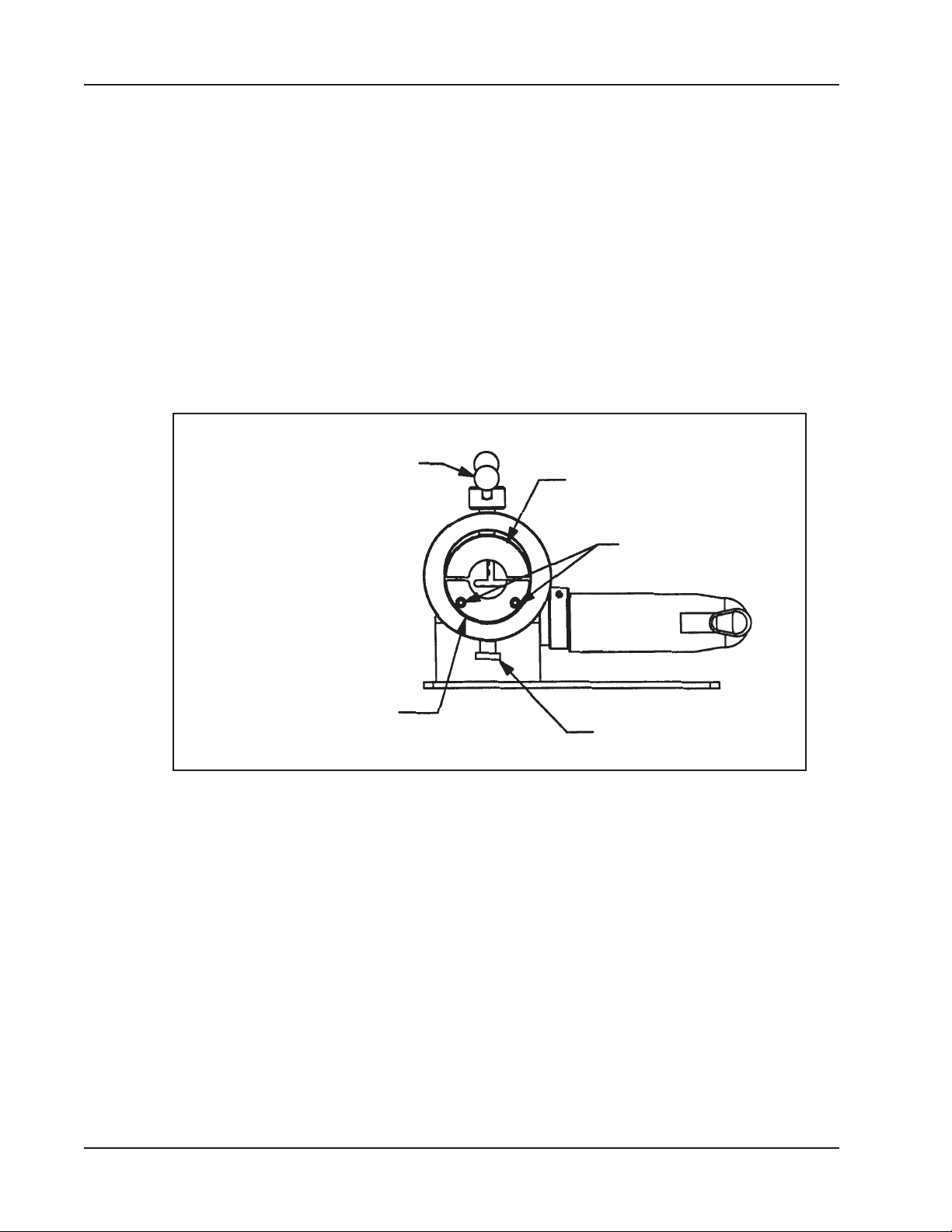
SADDLE INSTALLATION
Select the desired saddle size for the pipe or tube to be worked on.
Insert the lower saddle half into the lower front of the main housing.
Then thread the adjust knob in through the bottom of the main housing and into the
lower saddle half.
Slide the two (2) cap screws through the front of the lower saddle half and into front
of the main housing and tighten.
Place the upper saddle half into the front of the main housing.
Thread the shoulder screw into the top of the upper saddle half.
92-0547 : Rev. 140610
15
Page 16
TRI TOOL INC.
Back the adjustment screw assy out until the upper half of the saddle comes in
contact with the main housing.
MACHINING SEQUENCE
Place the pipe or tube into the saddles.
Verify a clearance of 1/8” (3 mm) between the tool bit(s) and the pipe or tube face as
held by the saddles.
Tighten the upper saddle by turning the adjustment screw assy to secure the pipe or
tube once the proper clearance has been veried.
Clamping Screw
Assembly
Upper Saddle Half
Lower Saddle Half
Cap Screws
Adjust Knob
16
92-0547 : Rev. 140610
Page 17
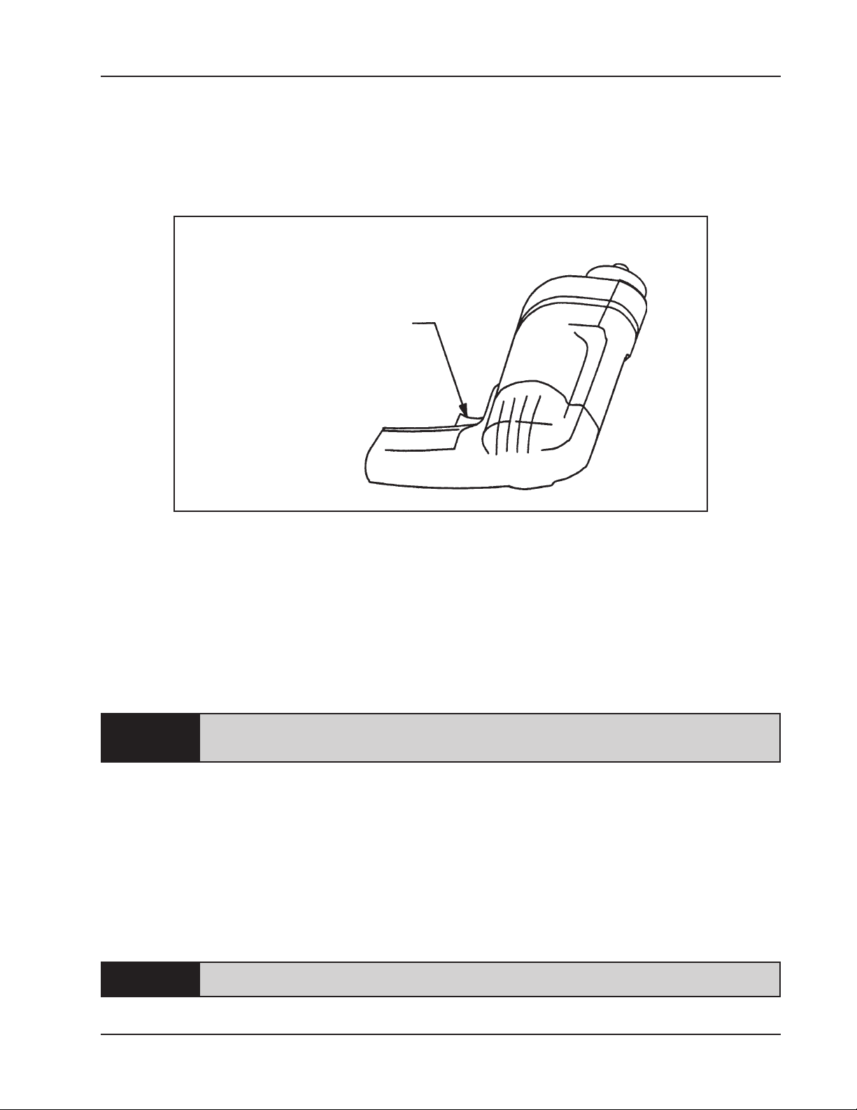
POWER REQUIREMENTS
Connect the proper power supply.
Depress the motor trigger.
Trigger Location
Model 302 Tube Squaring Machine
Trigger
Control and maintain constant cutting speed.
Refer to 'Cutting Speeds and Feeds' located in this manual for cutting speeds.
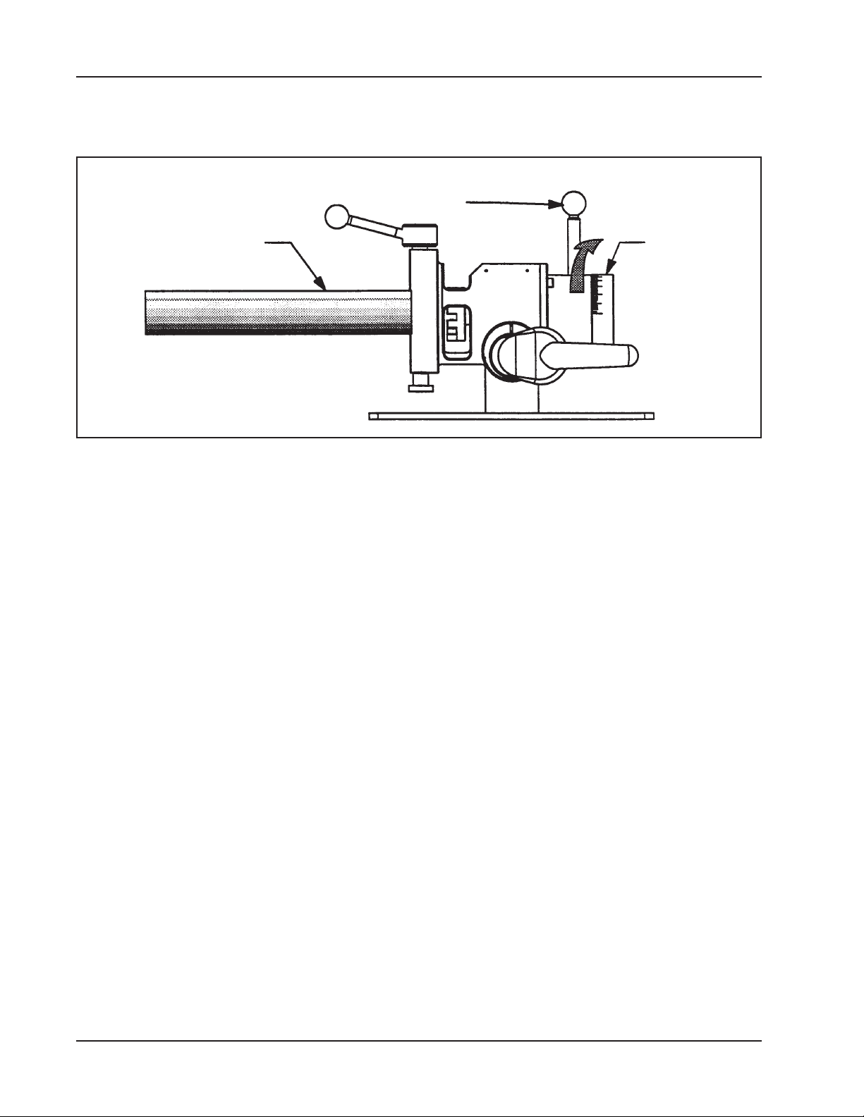
Rotate the feed knob clockwise to bring the cutting head and end of the tube or pipe
closer together.
Each line on the cover represents .001” (.025 mm) of feed travel.
CAUTION:
If the tube or pipe end is not square to the tube or pipe axis, the tool bit will contact
only a small segment of the tube or pipe during each revolution.
To avoid tool bit damage, the feed rate should be very slow until the tool bit is contacting the tube or pipe continually during at least one revolution.
Continue rotating the feed knob clockwise until the end of the tube or pipe is completely machined.
The actual machining operation will begin when the tool bit contacts the tube
or pipe.
CAUTION:
Be careful not to let the tool bit(s) cut into the saddle.
92-0547 : Rev. 140610
17
Page 18
TRI TOOL INC.
Discontinue feed and allow the cutting head to rotate one (1) to three (3) revolutions
to improve the nish of the prep surface.
Rotating the Feed Knob
Feed Knob
Tube or Pipe
Rotate the feed knob counterclockwise to separate the cutting head and the tube or
pipe.
Stop the tool rotation.
Release the trigger on the motor.
Rotate the feed knob counterclockwise until the cutting head clears the tube or pipe
by at least 1/8” (3 mm) or more.
Cover
18
Loosen the upper saddle to release the tube or pipe.
92-0547 : Rev. 140610
Page 19
Model 302 Tube Squaring Machine
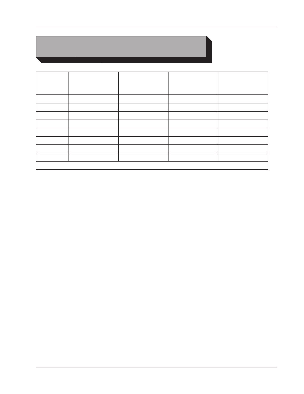
CUTTING SPEEDS AND FEEDS
Pipe DIA True DIA
.250" (6.4 mm) 255 318 382
.375" (9.5 mm) 170 212 255
.500" (12.7 mm) 127 159 191
.750" (19.1 mm) 85 106 127
1.00" (25.4 mm) 64 80 95
1.25" (31.8 mm) 51 64 76
1.50" (38.1 mm) 42 53 64
2.00" (50.8 mm) 32 40 48
*Cutting Speed (Approximately)
Use 200 surface inches per minute (5080 surface millimeters per minute) for:
Stainless steels in general when no coolant is allowed, all heavy-wall tube
and some chrome/molybdenum steels.
RPM for
200 in/min
(5080 mm/min)
RPM for
250 in/min
(6350 mm/min)
RPM for
300 in/min
(7620 mm/min)
Use 250 surface inches per minute (6350 surface millimeters per minute) for:
Mild steels and some thin wall stainless steels when coolants are permitted
and applied.
Use 300 surface inches per minute (7620 surface millimeters per minute) for:
Aluminum and thin-wall mild steel and tube with coolants.
92-0547 : Rev. 140610
19
Page 20
TRI TOOL INC.
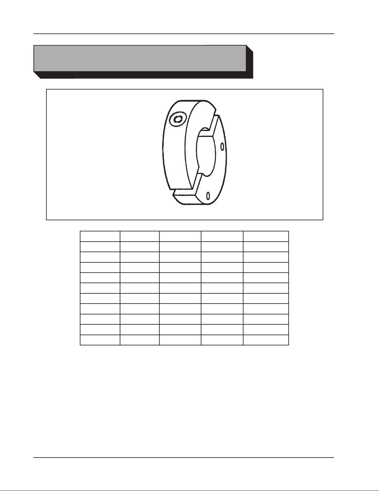
SADDLE SETS
Pipe Size Fraction Decimal Metric Saddle P/N
1/4" .250" 6.4 mm 67-3523
3/8" .375" 9.5 mm 67-3532
1/2" .500" 12.7 mm 67-3545
3/4" .750" 19.1 mm 67-3567
1" 1.000" 25.4 mm 67-3582
1 1/4" 1.250" 31.8 mm 67-3589
1 1/2" 1.500" 38.1 mm 67-3598
2" 2.000" 50.8 mm 67-3612
2 3/8" 2.375" 60.3 mm 67-3619
Saddles are made of Stainless Steel.
Contact TRI TOOL Inc. for sizes not listed.
20
92-0547 : Rev. 140610
Page 21
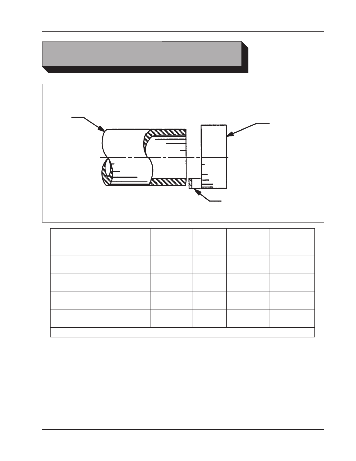
TOOL BITS
Tool Bit, Tube Squaring
Pipe
Model 302 Tube Squaring Machine
Cutting Head
Range
.187" OD thru 2.00" OD
(4.8 mm OD thru 50.8 mm OD)
.187" OD thru 2.00" OD
(4.8 mm OD thru 50.8 mm OD)
.187" OD thru 2.00" OD
(4.8 mm OD thru 50.8 mm OD)
.187" OD thru 2.00" OD
(4.8 mm OD thru 50.8 mm OD)
*M42
Max Wall
Thickness
.200"
(5.1 mm)
.200"
(5.1 mm)
.200"
(5.1 mm)
.200"
(5.1 mm)
Pipe or
Tube
Material
CS
SS
SS
Inconel
Tool Bit, Tube Squaring
Tool Bit
Height
.750"
(19.1 mm)
.750"
(19.1 mm)
.750"
(19.1 mm)
.750"
(19.1 mm)
Squaring
Tool Bit P/N
99-1480
DURABIT 1
DURABIT 1
99-3650*
92-0547 : Rev. 140610
21
Page 22
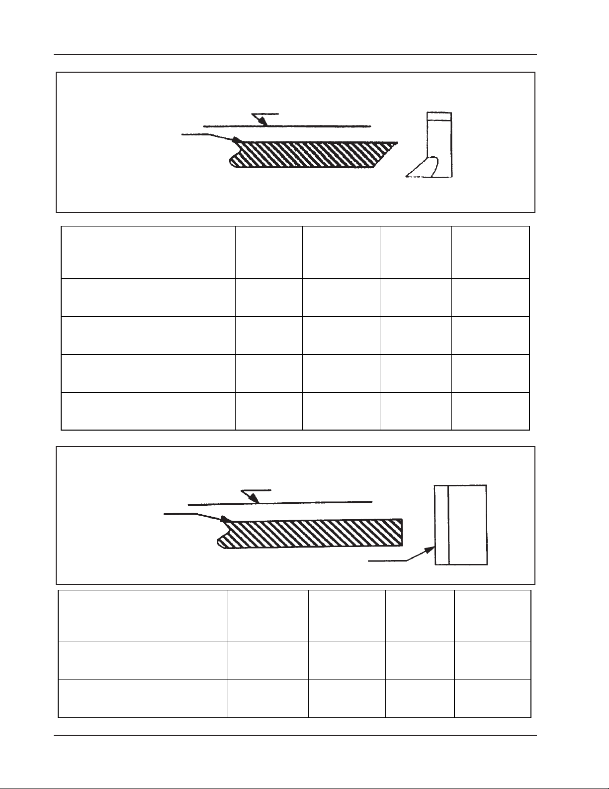
TRI TOOL INC.
Bevel Tool Bit
Pipe or Tube
Centerline of Pipe or Tube
Tool Bit
Bevel
Range
.187” OD thru 1.00” OD
(4.8 mm OD thru 25.4 mm OD)
.100” OD thru 2.38” OD
(25.4 mm OD thru 60.5 mm OD)
.187” OD thru 1.00” OD
(4.8 mm OD thru 25.4 mm OD)
.100” OD thru 2.38” OD
(25.4 mm OD thru 60.5 mm OD)
Facing Tool Bit
Pipe or Tube
Max
Wall
Thickness
.200”
(5.1 mm)
.200”
(5.1 mm)
.200”
(5.1 mm)
.200”
(5.1 mm)
Centerline of Pipe or Tube
Pipe or Tube
Material
SS 37.50° 99-0210
SS 37.50° 99-0276
CS 45° 99-5085
SS 45° 99-5994
Bevel
Angle
Bevel
Tool Bit
P/N
Facing
Range
.187” OD thru 2.00” OD
(4.8 mm OD thru 50.8 mm OD )
.187” OD thru 2.00” OD
(4.8 mm OD thru 50.8 mm OD )
22
Max
Wall
Thickness
.200”
(5.1 mm)
.200”
(5.1 mm)
Tool Bit
Pipe
or Tube
Material
CS
SS
Tool
Bit
Height
.625”
(15.9 mm)
.625”
(15.9 mm)
Facing Tool
Bit P/N
99-1406
99-1406
92-0547 : Rev. 140610
Page 23

Model 302 Tube Squaring Machine
TROUBLESHOOTING
Problem: The Tool Bit Chatters.
The tool bit is loose or overextended.
The tool bit is damaged.
The tool holder is too loose in the slides.
The cutting speed is too fast.
The clamping pads are loose on the pipe or tube.
Cutting uid is required.
The main bearing pre-load is loose.
Problem: There is excessive Tool Bit wear.
The pipe or tube material is too hard or abrasive.
The cutting speed is too fast.
Cutting uid is required.
A dull Tool Bit is causing surface hardening conditions (Stainless pipe or tub-
ing).
There is scale or other foreign matter on the pipe or tube, which is dulling the
tool bit at the start of the cut.
The tool bit is incorrect for the material being cut.
NOTE:
Problem: Thesurfacenishisrough.
The tool bit is dull, chipped, etc.
Metal buildup on the cutting edge of the tool bit is creating a false cutting
Cutting uid is required.
The cutting speed is incorrect.
Consult the factory for tool bit material recommendations for specialty pipe or
tube materials.
edge.
Problem: There is a loss of power.
The motor is disconnected from the power supply.
The power cord or the air line is broken.
The power cord or air line is too long.
92-0547 : Rev. 140610
23
Page 24

TRI TOOL INC.
Problem: The electric motor will not start.
The power supply is shut off.
The electric motor is damaged and will not run free.
Problem: The air motor will not start.
The air power supply is shut off.
The air motor is damaged and will not run free. The air motor needs lubrica-
tion.
Add lubrication and do not run the air motor for a few minutes, then running
the motor. Tap on the side of the air motor casing lightly with a piece of wood
or with a soft rubber mallet just in case the vanes may be sticking.
Sand or other foreign material may be in the vanes of the air motor.
24
92-0547 : Rev. 140610
Page 25
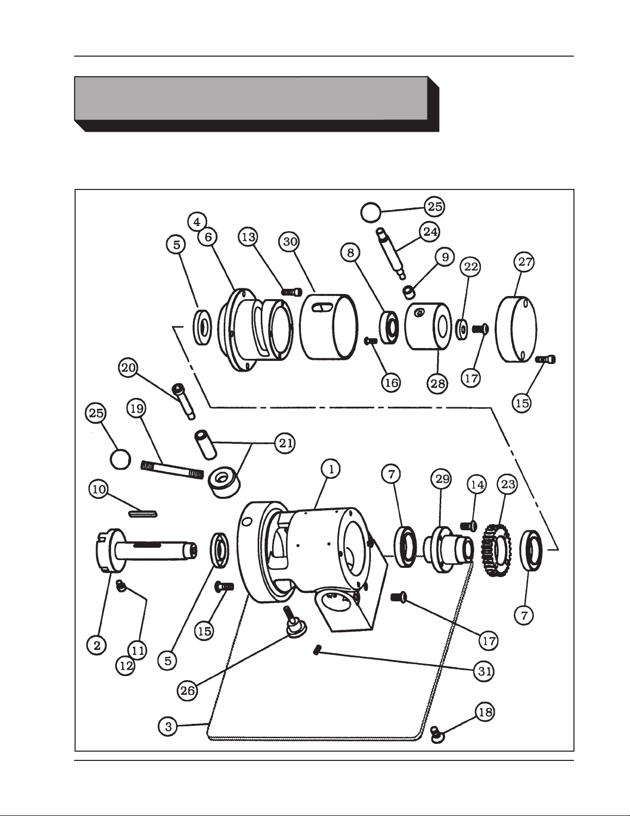
Model 302 Tube Squaring Machine
ILLUSTRATED PARTS BREAKDOWN
MODEL 302, TUBE SQUARING MACHINE
SUB-ASSY (REF. P/N 02-2174)
92-0547 : Rev. 140610
25
Page 26

TRI TOOL INC.
Parts List, Model 302 Tube Squaring Machine Sub-Assy (Ref. P/N 02-2174)
Item Part
No. No. Description Qty
1. 19-0660 HOUSING, MAIN 1
2. 20-0561 SHAFT, FEED 1
3. 24-1256 PLATE, MOUNTING 1
4. 27-0455 ADAPTER, FEED 1
5. 28-0231 SEAL 2
6. 28-0234 O-RING 1
7. 29-0011 BEARING, BALL 2
8. 29-0020 BEARING, BALL 1
9. 29-0311 BEARING, ROLLER 1
10. 31-0142 KEY, ROUND ENDS 1
11. 33-0037 SCREW, CAP, 1/4-20 X 3/8" 1
12. 33-0038 SCREW, CAP, 1/4-20 X 1/2" 4
13. 33-0040 SCREW, CAP, 1/4-20 X 3/4" 4
14. 33-0041 SCREW, CAP, 1/4-20 X 7/8" 4
15. 33-0042 SCREW, CAP, 1/4-20 X 1" 4
16. 33-0278 SCREW, BUTTON, #10-24 X 3/8" 6
17. 33-0292 SCREW, BUTTON, 5/16-18 X 5/8" 3
18. 33-0369 SCREW, FLAT, 5/16-18 X 3/4" 4
19. 33-1424 STUD, HANDLE 1
20. 33-1440 SCREW, SHOULDER, 3/8" X 1 3/4" 1
21. 33-1839 SCREW ASSEMBLY, ADJUSTMENT 1
22. 34-0278 WASHER, CAPTURE 1
23. 39-0725 GEAR, WORM, BRONZE, 30 T 1
24. 41-0106 HANDLE, FEED 1
25. 42-0076 KNOB, BALL 2
26. 42-0143 KNOB, ADJUST 1
27. 43-0426 COVER 1
28. 44-0417 SPACER, FEED 1
29. 46-0384 SLEEVE, DRIVE 1
30. 46-0385 SLEEVE, FEED 1
31. 54-0374 PLUG, PRESSURE, FLUSH SKT, 1/4" NPT 1
NOT SHOWN
36-0021 WRENCH, T, 3/16" HEX 1
86-0199 CASE, CARRYING 1
26
92-0547 : Rev. 140610
Page 27
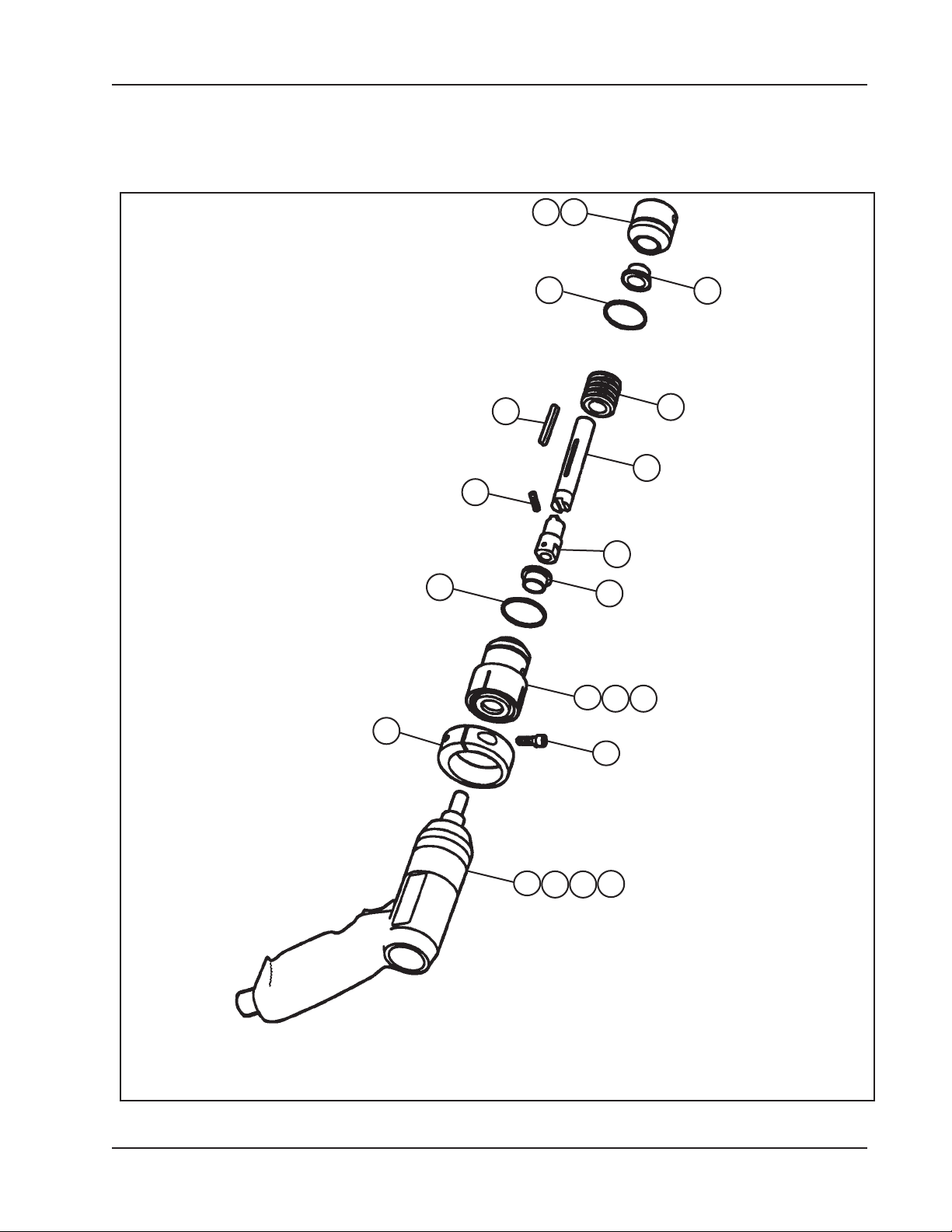
Model 302 Tube Squaring Machine
MOTOR ASSEMBLY, AIR, 302A (P/N 57-0213)
167
12
4
5
1
8
2
4
10
3
117
6
10
9
92-0547 : Rev. 140610
13
17
1514
27
Page 28

TRI TOOL INC.
Parts List, Motor Assembly, Air, 302A (P/N 57-0213)
Item Part
No. No. Description Qty
1. 20-0617 SHAFT, DRIVE 1
2. 20-0618 SHAFT, DRIVE, 3/8-24 UNF 1
3. 28-0218 SEAL, GREASE 1
4. 28-0233 O-RING 2
5. 31-0115 KEY, ROUND ENDS 1
6. 33-0041 SCREW, CAP, 1/4-20 X 7/8" 1
7. 33-0292 SCREW, BUTTON, 5/16-18 X 5/8" 2
8. 33-0619 SCREW, SET, #10-32 X 1/4", CUP PT 1
9. 39-0005 WORM 1
10. 45-0221 BUSHING, FLANGE, 5/8" ID 2
11. 46-0390 SLEEVE, MOTOR, AIR 1
12. 47-0919 BRACKET, CLAMP 1
13. 53-0045 VALVE, FLOW CONTROL, 1/4" NPT 1
14. 54-0149 COUPLING, MALE, QD, HOSE TO PIPE 1
15. 54-0201 CAP, YELLOW 1
16. 54-0347 PLUG 1
17. 57-0212 MOTOR, AIR, PISTOL GRIP 1
28
92-0547 : Rev. 140610
Page 29
Model 302 Tube Squaring Machine
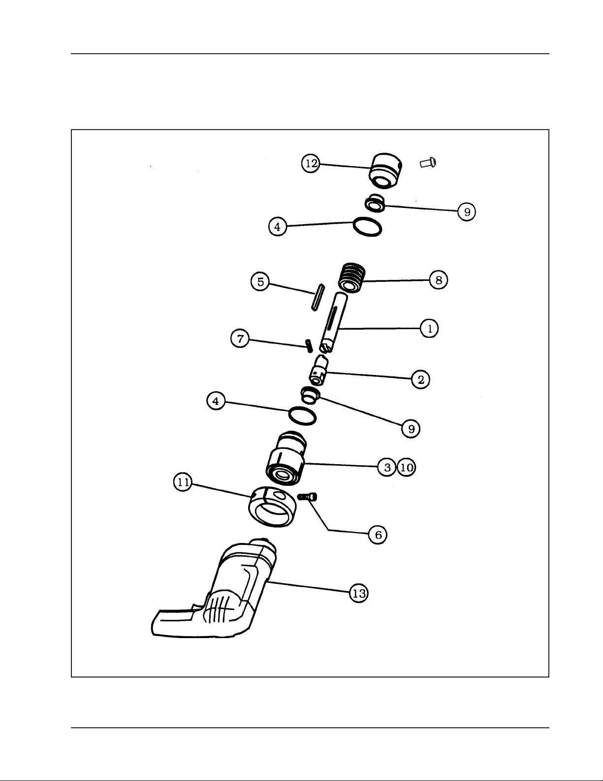
MOTOR ASSEMBLY, ELECTRIC 110V (P/N 58-0184)
AND 220V (P/N 58-0080)
92-0547 : Rev. 140610
29
Page 30

TRI TOOL INC.
Parts List, Motor Assembly, Electric, 110 VAC (P/N 58-0184)
Item Part
No. No. Description Qty
1. 20-0617 SHAFT, DRIVE 1
2. 20-0619 SHAFT, DRIVE, 1/2-20 UNF 1
3. 28-0245 SEAL, GREASE 1
4. 28-0233 O-RING 2
5. 31-0115 KEY, ROUND ENDS 1
6. 33-0041 SCREW, CAP, 1/4-20 X 7/8" 1
7. 33-0619 SCREW, SET, #10-32 X 1/4", CUP PT 1
8. 39-0005 WORM 1
9. 45-0221 BUSHING, FLANGE, 5/8" ID 2
10. 46-0586 SLEEVE, MOTOR 1
11. 47-1111 BRACKET CLAMP 1
12. 54-0347 PLUG 1
13. 58-0183 MOTOR, ELECTRIC, MOD, 110 VAC (Milwaukee) 1
NOT SHOWN
33-0292 SCREW, BUTTON, 5/16-18 X 5/8" REF
Parts List, Motor Assembly, Metabo, 110 VAC (P/N 58-0301)
Item Part
No. No. Description Qty
1. 20-0617 SHAFT, DRIVE 1
2. 20-0619 SHAFT, DRIVE 1
3. 28-0245 SEAL, GREASE 1
4. 28-0233 O-RING 2
5. 31-0115 KEY, ROUND ENDS 1
6. 33-0041 SCREW, CAP, 1/4-20 X 7/8" 1
7. 33-0619 SCREW, SET, #10-32 X 1/4", CUP PT 2
8. 39-0005 WORM 1
9. 45-0258 BUSHING, FLANGE, 5/8" ID 2
10. 46-0411 SLEEVE, MOTOR 1
11. 47-1111 BRACKET CLAMP 1
12. 54-0347 PLUG 1
13. 58-0277 MOTOR, C.W.ELEC., METABO, 110V 1
NOT SHOWN
33-0292 SCREW, BUTTON, 5/16-18 X 5/8" REF
30
92-0547 : Rev. 140610
Page 31

Model 302 Tube Squaring Machine
Parts List, Motor Assembly, Electric, 220 VAC (P/N 58-0080)
Item Part
No. No. Description Qty
1. 20-0617 SHAFT, DRIVE 1
2. 20-0619 SHAFT, DRIVE, 1/2-20 UNF 1
3. 28-0245 SEAL, GREASE 1
4. 28-0233 O-RING 2
5. 31-0115 KEY 1
6. 33-0041 SCREW, CAP, 1/4-20 X 7/8" 1
7. 33-0619 SCREW, SET, #10-32 X 1/4", CUP PT 2
8. 39-0005 WORM 1
9. 45-0258 BUSHING, FLANGE, 5/8" ID 2
10. 46-0411 SLEEVE, MOTOR 1
11. 47-1111 BRACKET, CLAMP 1
12. 54-0347 PLUG 1
13. 58-0232 MOTOR, MOD., ELECTRIC, 220 VAC (Bosch) 1
NOT SHOWN
33-0292 SCREW, BUTTON, 5/16-18 X 5/8" REF
92-0547 : Rev. 140610
31
 Loading...