

Page 1
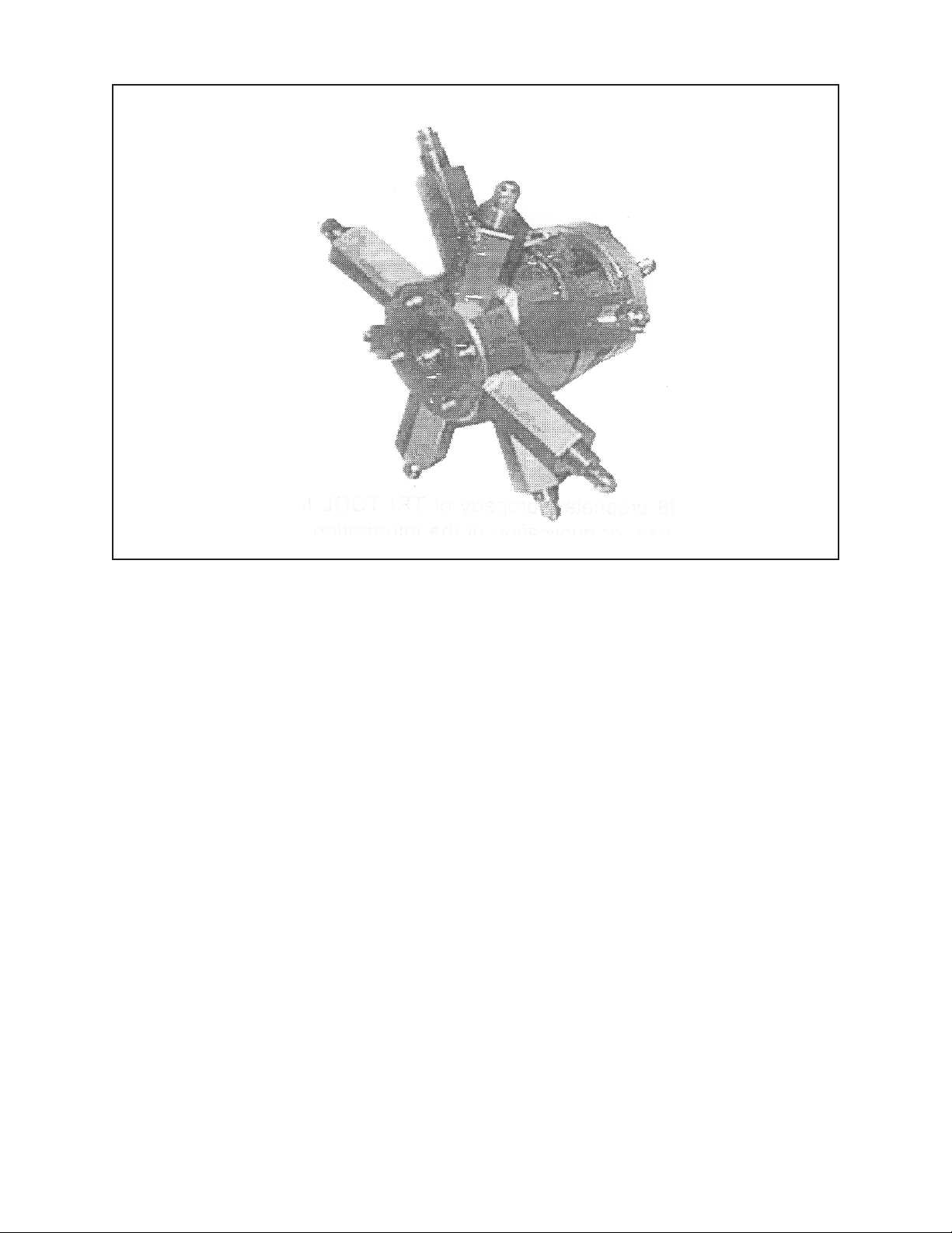
TABLE OF CONTENTS
CUSTOMER MESSAGE Inside Front Cover
SAFETY PRECAUTIONS 3
92-0738 Rev. 980331
Model 212B Miter Mandrel Head for SP/FF
GENERAL DESCRIPTION 6
SPECIFICATIONS 7
MAINTENANCE 9
OPERATION 11
DISASSEMBLY AND ASSEMBLY 20
ACCESSORIES 21
ILLUSTRATED PARTS BREAKDOWN 22
TOOL BIT RESHARPENING POLICY Inside Back Cover
WARRANTY INFORMATION Inside Back Cover
Page 2

Copyright 1998
Proprietary property of TRI TOOL Inc.
No reproduction, use, or duplication of the information
shown hereon is permitted without the express written
consent of TRI TOOL Inc.
Page 3

SAFETY PRECAUTIONS
IN GENERAL
When using rotating head cutting equipment, basic safety precautions should always
be followed to reduce the risk of personal injury.
Operate this tool only in accordance with specific operating instructions.
Do not override the deadman switch on the power unit. Locking down, ob-
WARNING:
DRESS CONSIDERATIONS
structing, or in any way defeating the deadman switch on the power drive unit
may result in serious injury.
Model 212B Miter Mandrel Head for SP/FF
Use standard safety equipment. Hard hats, safety shoes, safety harnesses, protective clothes, and other safety devices should always be used when appropriate.
Use safety glasses. Do not operate cutting tools without eye protection.
Dress properly. Do not wear loose clothing or jewelry. They can be caught in rotating and moving parts. Avoid slippery floors or wear nonskid footwear. If you have
long hair, wear protective hair covering to contain it.
WORK AREA
Keep the work area clean. Cluttered work areas and benches invite injuries.
Consider the work area environment. Keep the area well lit. Keep electrical cords,
cables, rags, rigging straps, and etc. clear of rotating equipment. Do not use powercutting tools in the presence of flammable liquids and gasses.
Keep visitors away. Do not let visitors or untrained personnel at or near operating
tools. Enforce eye protection requirements for all observers.
Do not over reach. Keep proper footing at all times.
Stay alert. Watch what you are doing. Use common sense. Do not operate tools
when you are tired.
92-0738 : Rev. 980331
3
Page 4

TRI TOOL INC.
TOOL CARE
Maintain tools with care. Keep tools in good operating condition. Sharp tool bits
perform better and safer than dull tool bits. Well maintained tools function properly
when needed.
Check for damaged parts. If a tool has malfunctioned, been dropped or hit, it must
be checked for damage. Run no-load tests and feed function checks. Do a complete visual inspection.
Electric motors. Use only with proper AC voltage power sources and observe all
normal electric shock hazard procedures.
Do not abuse power and control cords. Pulling or running over cords and cables
can result in electrical shock hazards and malfunctions. Keep control and power
cords out of all cutting fluids and water.
Hydraulic drives. Observe proper procedures for electrically driven power sources.
Avoid damage to hydraulic lines. Keep quick-disconnects clean. Grit contamination
causes malfunctions.
Air tools. Check the exhaust muffler. Broken or damaged mufflers can restrict air
flow or cause excessive noise. Use air motors only with a filtered, lubricated and
regulated air supply. Dirty air, low-pressure air or over pressure air will cause malfunctions, including delayed starting.
AREA EQUIPMENT
Secure work. Whenever possible use clamps, vises, chains and straps to secure
pipe.
Make sure the tool is secured; it is safer to have both hands free to operate the tool.
TOOL USE
Use the right tool and tool bit for the job. Do not use a tool, which is incorrect for the
job you are doing.
Keep the tool bits fully engaged in the tool bit holders. Loose bits are a safety hazard.
4
92-0738 : Rev. 980331
Page 5

Model 212B Miter Mandrel Head for SP/FF
Disconnect power supply during setup and maintenance. Use all ‘Stop’ or Shut off’
features available when changing or adjusting tool bits, maintaining the tool, or when
the tool is not in use.
Remove adjusting keys and wrenches before applying power to the equipment.
Develop a habit of checking the tool before turning it on to make sure that all keys
and wrenches have been removed.
Do not force tools. Tools and tool bits function better and safer when used at the
feed and speed rate for which they were designed.
Do not reach into rotating equipment. Do not reach into the rotating head stock to
clear chips, to make adjustments, or to check surface finish. A machine designed to
cut steel will not stop for a hand or an arm.
Handle chips with care. Chips have very sharp edges and are hot. Do not try to pull
chips apart with are hands; they are very tough.
Avoid unintentional starts. Do not carry or handle tools with your hand on the operating switches or levers. Do not lay the tool down in a manner that will start the
drive. Do not allow the tool to flip around or move when adjusting or changing tool
bits.
Store idle tools properly. Disconnect tools from the power source and store in a safe
place. Remove tool bits for safe handling of the tool.
92-0738 : Rev. 980331
5
Page 6
TRI TOOL INC.
GENERAL DESCRIPTION
The Model 212B SP Miter Mandrel Head is an accessory option which is used to
expand the versatility of the Model 212B by allowing in-situ set up on irregular pipe,
fittings and valves.
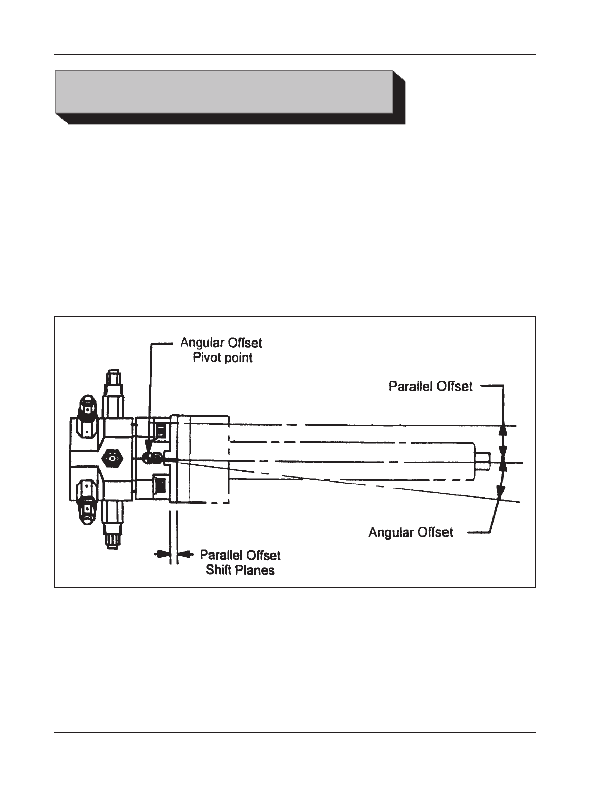
The Miter Mandrel Head is secured to the ID of the work-piece by way of eight
individually adjusted ‘Jackscrews’ in two separate rows.
Once secured, two distinct types of adjustments are easily performed:
Angular Offset
Parallel Offset
Adjustment
Planes and
Offsets
With the Angular Offset Adjustment, the Mandrel Shaft can be precisely aligned with
the work-piece, even though the ID of the work-piece might be irregular, or it may be
adjusted up to 5° from the centerline in any direction desired to give a mitered prep.
The Parallel Offset adjustment accurately re-centers the Mandrel Shaft after the
Angular Offset adjustment has been made.
Both adjustments are accomplished with the aid of an ‘Indicating Sleeve’ and Dial
Indicator Kit.
6
92-0738 : Rev. 980331
Page 7
SPECIFICATIONS
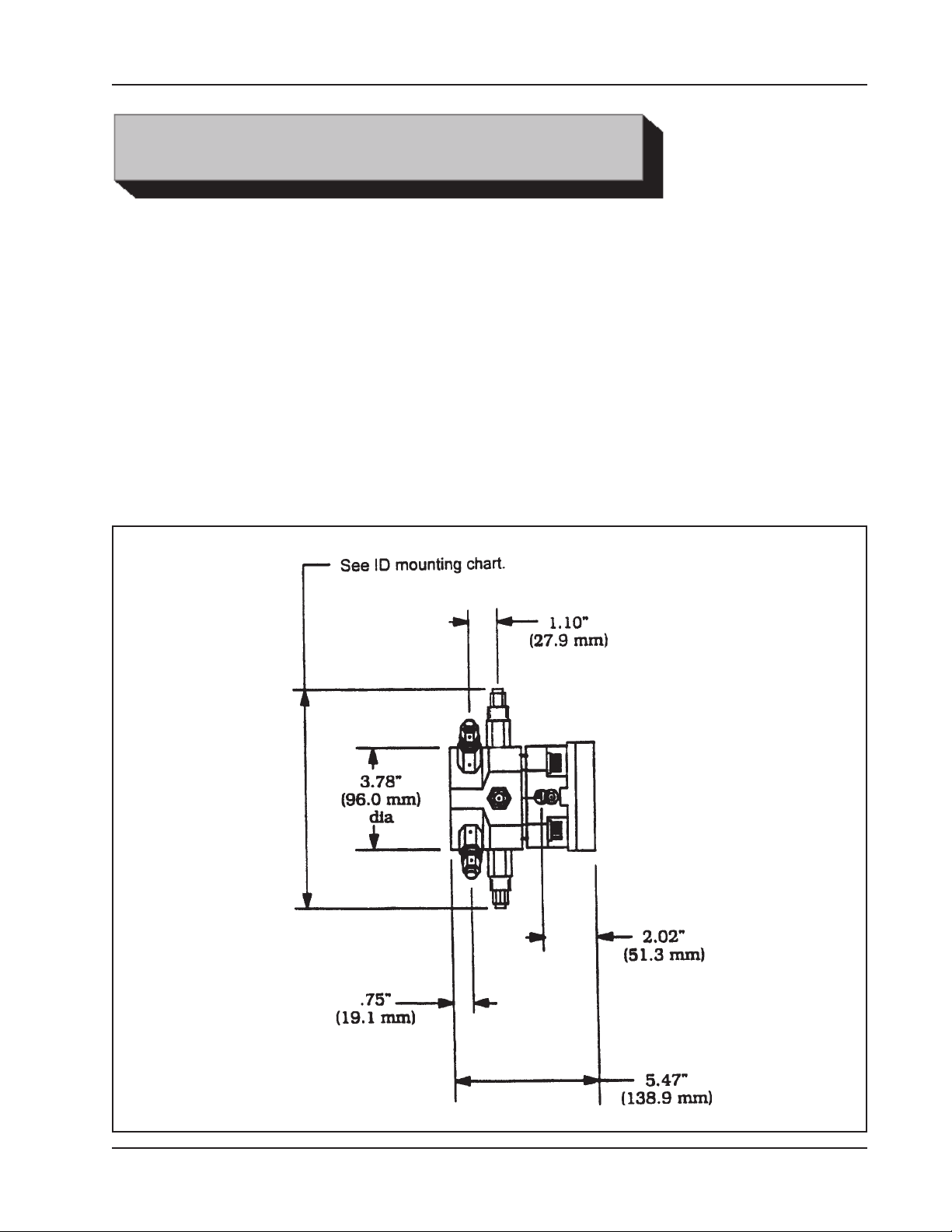
Weight
20 lbs (9 kg)*
*Weight will vary with the Jackscrew size.
Pipe Holding Capacities
Basic Pipe Size
6” pipe up to sch 120 through 24” pipe sch 30 and up. (Using Adapter
Extension Plate)
Model 212B Miter Mandrel Head for SP/FF
Envelope
Drawing
92-0738 : Rev. 980331
7
Page 8
TRI TOOL INC.
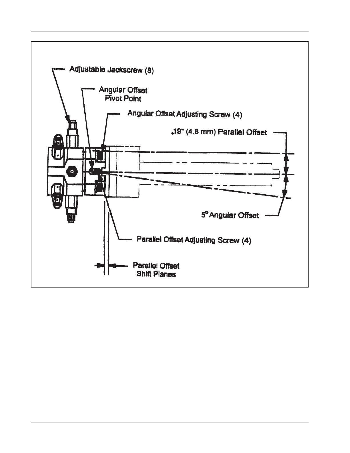
Location Identifications
8
92-0738 : Rev. 980331
Page 9
Model 212B Miter Mandrel Head for SP/FF
MAINTENANCE
Tri Tool Miter Mandrel Heads are precision tools that will perform excellently if they
are well maintained.
Keep the Miter Mandrel Head clean.
Brush away any chips or other debris with a soft bristle brush.
Wipe the Miter Mandrel Head down with a lightly oiled rag.
Inspect the Miter Mandrel Head before each use.
Check for stripped threads, burred, worn or missing parts and replace when
necessary.
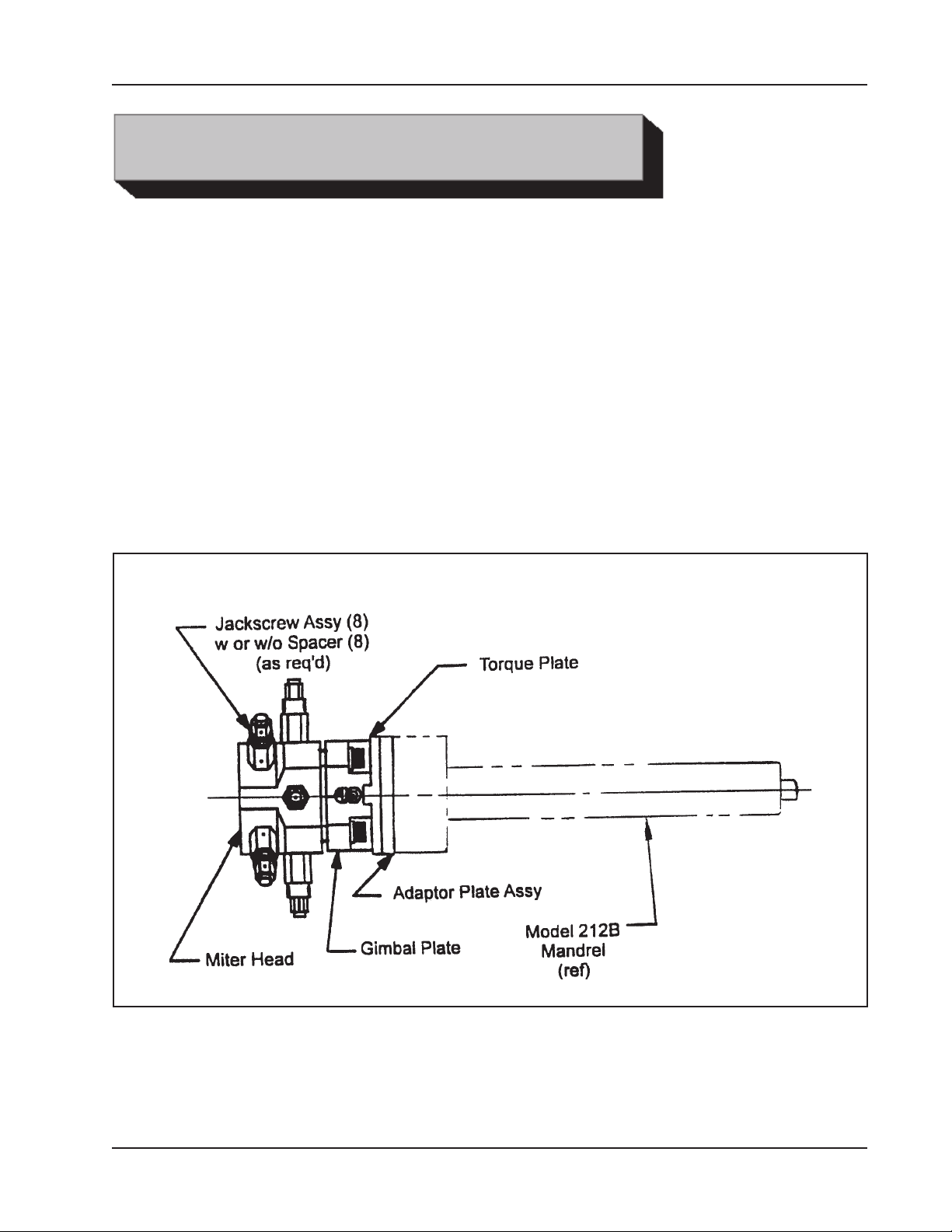
Identification of various major parts
92-0738 : Rev. 980331
9
Page 10

TRI TOOL INC.
Identification of Various Major Parts
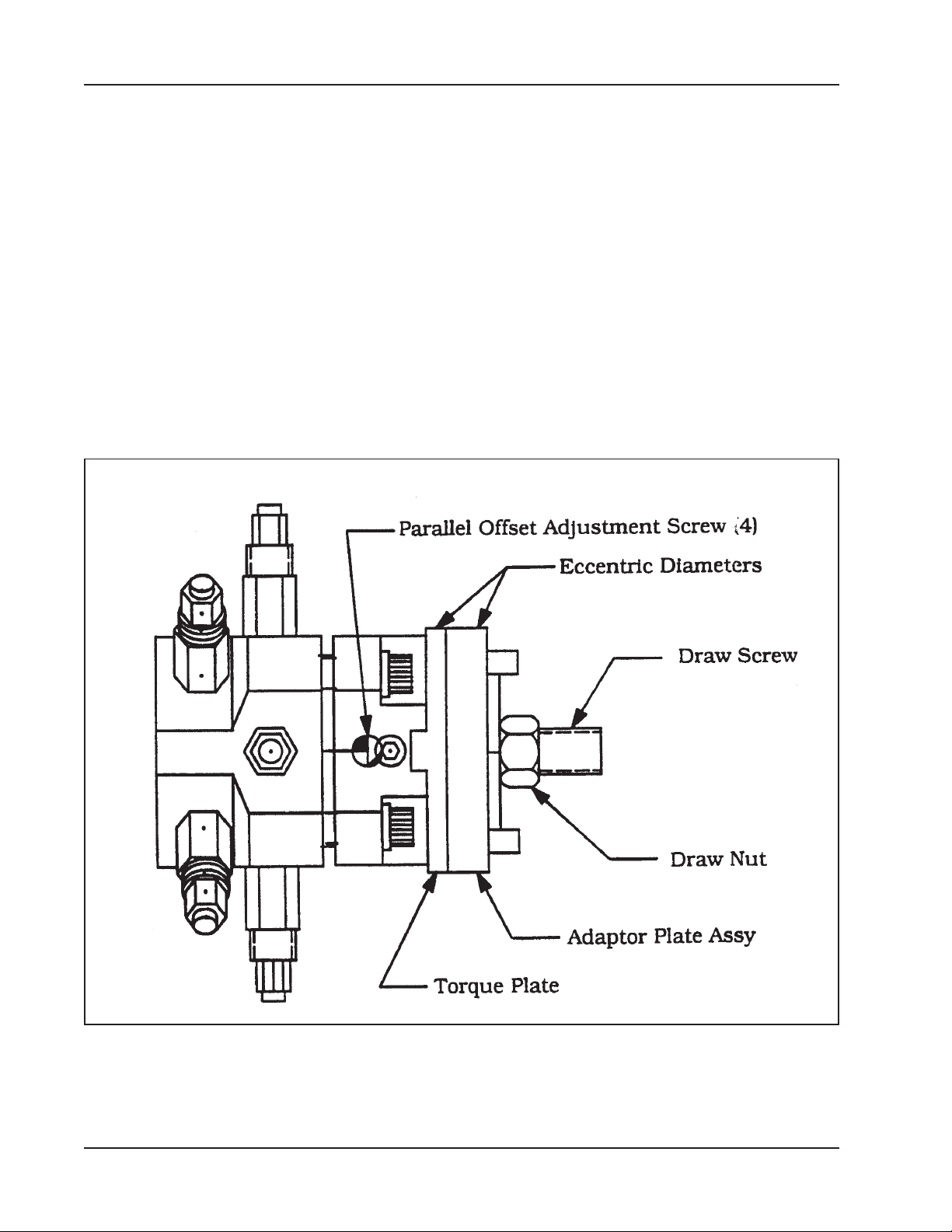
Occasionally back off the four (4) Parallel Offset Adjustment Screws, remove the
Draw Nut, Adapter Plate Assembly and the Torque Plate.
Check all parts for cracks, burrs, etc.
Remove the four (4) Angular Offset Adjusting Screws and Spherical Washers and
separate the Gimbal Plate from the Mandrel Head.
Check the spherical bearing surface for burrs and other defects.
Do not reuse any parts that show evidence of cracking, bending or over stressing.
Apply a very thin film of general purpose grease or anti-seize to the spherical
surface of the Gimbel Plate, two or three drops of light oil on each of the four (4)
Spherical Washers, grease or anti-seize to both sides of the Torque Plate and
grease and anti-seize or oil to all screws, nuts and threads. Reassemble in the
reverse order of disassembly.
10
92-0738 : Rev. 980331
Page 11
Model 212B Miter Mandrel Head for SP/FF
OPERATION
CAUTION: Never attempt to manually lift the Miter Mandrel Head with the
212B installed.
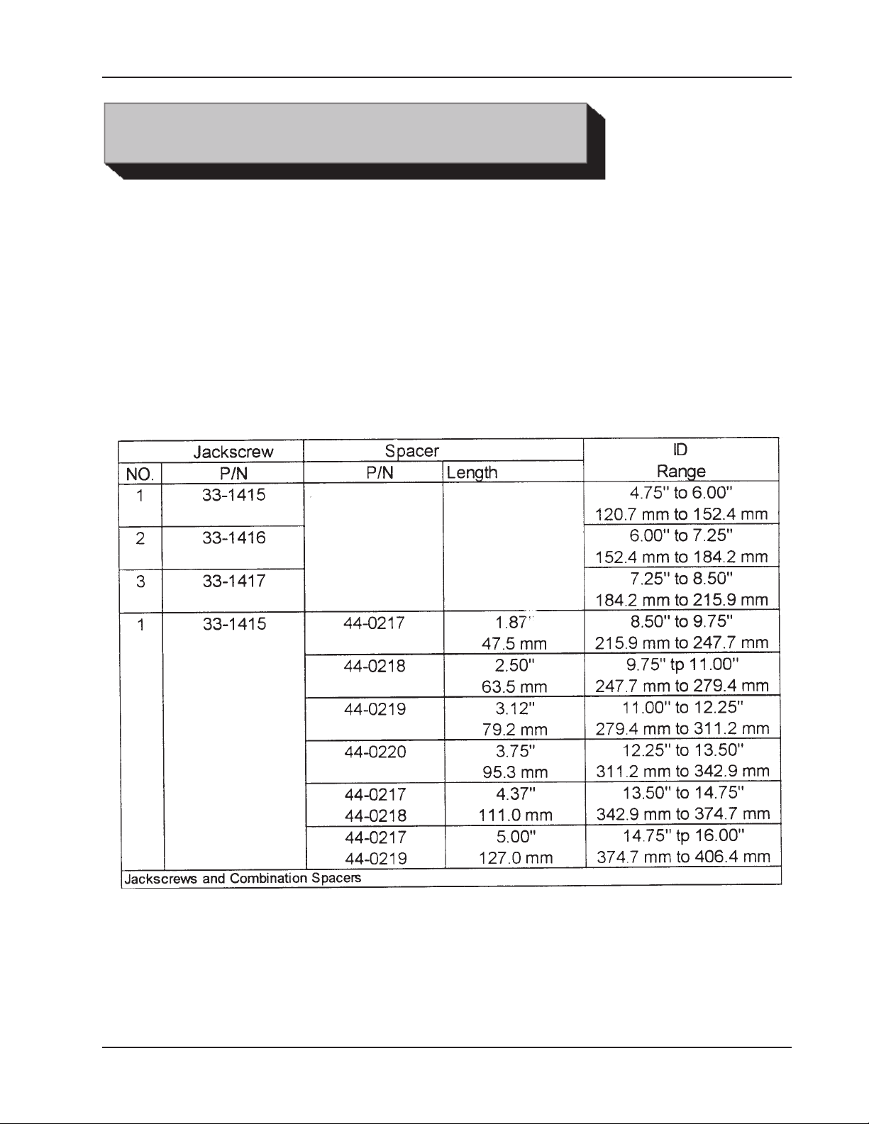
The eight (8) Jackscrews are removable. They are made of heat-treated steel and
have a slight spherical radius on the surface that contacts the work-piece.
On most surfaces, this provides for excellent holding power with virtually no marring
of the work-piece.
Three (3) lengths of Jackscrews and four (4) lengths of Spacers are provided.
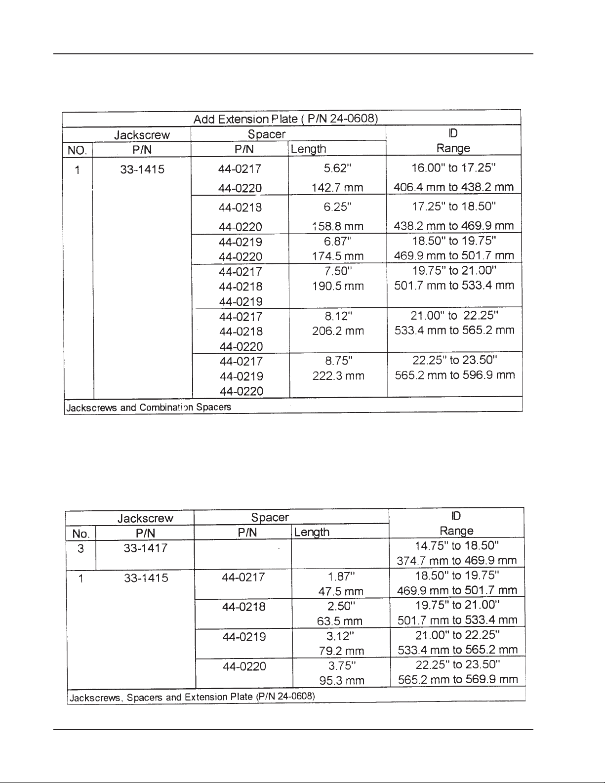
Combinations of Spacers will extend the ID Range.
92-0738 : Rev. 980331
11
Page 12
TRI TOOL INC.
The Extension Plate helps stabilize the miter mandrel head on the extended ID
Ranges. It mounts to the front of the miter mandrel head (P/N 21-0101).
Turn the Jackscrews to a diameter slightly smaller than the bore of the work-piece.
Before the Miter Mandrel Head is mounted on the work-piece, both the Angular
Offset and the Parallel Offset Adjustments should be approximately centered.
12
92-0738 : Rev. 980331
Page 13
Model 212B Miter Mandrel Head for SP/FF
This will permit a maximum range of adjustment for final settings after the mandrel
has been mounted.
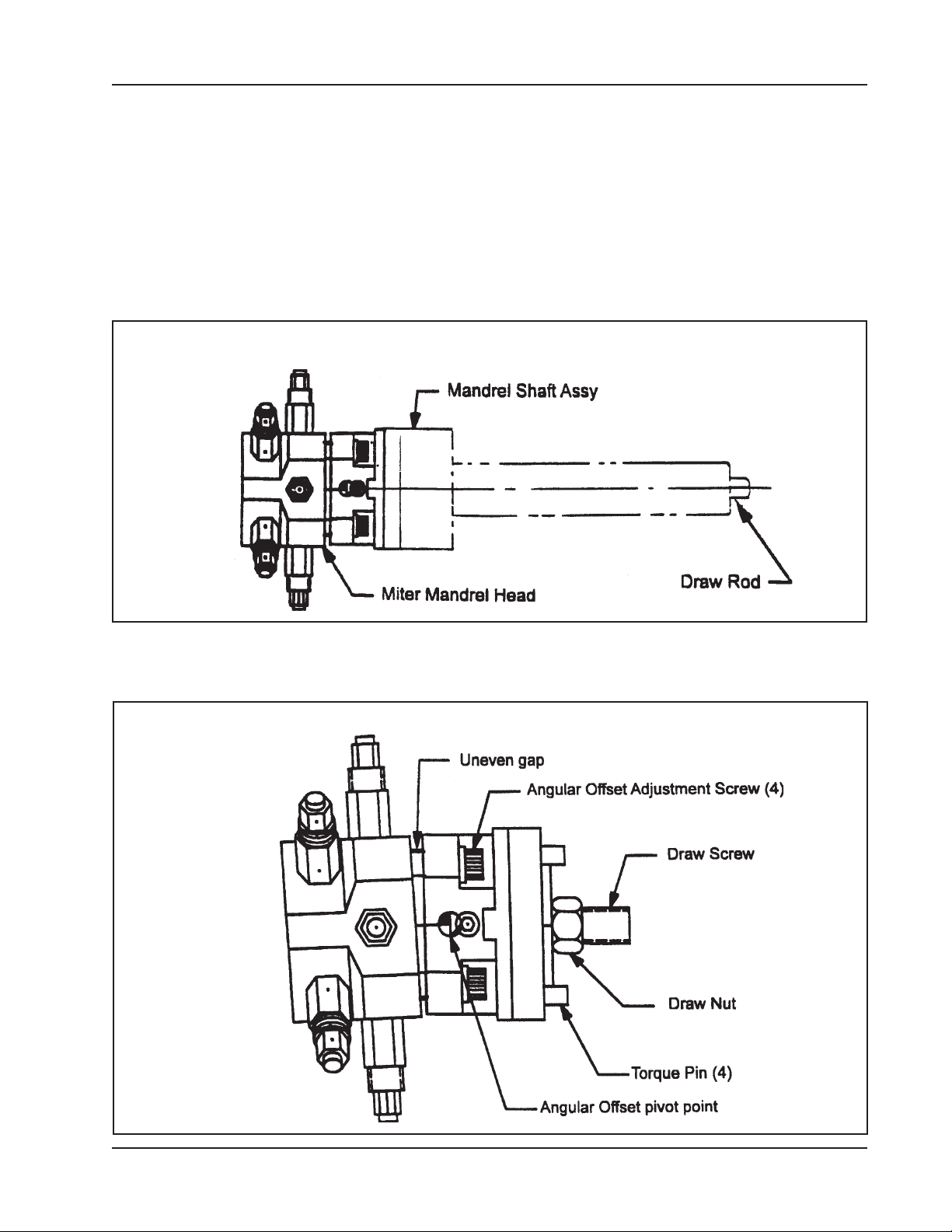
By turning the Draw Rod counterclockwise, the mandrel Shaft Assembly can be
removed from the Miter Mandrel Head.
NOTE: To make the parallel Offset Adjustment, all four (4) screws must be
slightly loose.
Mandrel Shaft
Asst and Draw
Rod Locations
Check the gap between the Gimbal Plate and the Mandrel Head to see that it is
approximately even all around.
Angular Offset
Adjustmnet
92-0738 : Rev. 980331
13
Page 14
TRI TOOL INC.
If it is not, then loosen the Angular Offset Adjustment Screws where the gap is
small and tighten the Angular Offset Adjustment Screws where the gap is
wide.
Lightly tighten the Draw Nut.
NOTE: All four of the Angular Offset Adjustment Screws must be used in
conjunction with each other.
All Screws must be at least slightly loose to allow movement.
If the Mandrel shaft is to be drawn directly toward one screw, the opposite
screw must be loosened far enough to allow for the take up before the near
screw is tightened.
Parallel Offset
Adjustment
14
Leave the Draw Nut slightly loose during and after the Angular Offset adjustment.
Check to see that the Adapter Plate Assembly is centered to the Gimbal Plate.
92-0738 : Rev. 980331
Page 15
Model 212B Miter Mandrel Head for SP/FF
If not, locate the four (4) Parallel Offset Adjusting Screws and back off one (1)
or two (2) screws where the Adapter Plate Assembly is ‘in’.
Tightening to opposite one or two screws will bring the Adapter Plate Assembly
toward the center.
NOTE: To make the Parallel Offset adjustment. All four (4) screws must be
slightly loose.
Once the Adapter Plate Assembly has been roughly aligned and centered,
temporarily snug all of the Adjustment Screws and the Draw Nut.
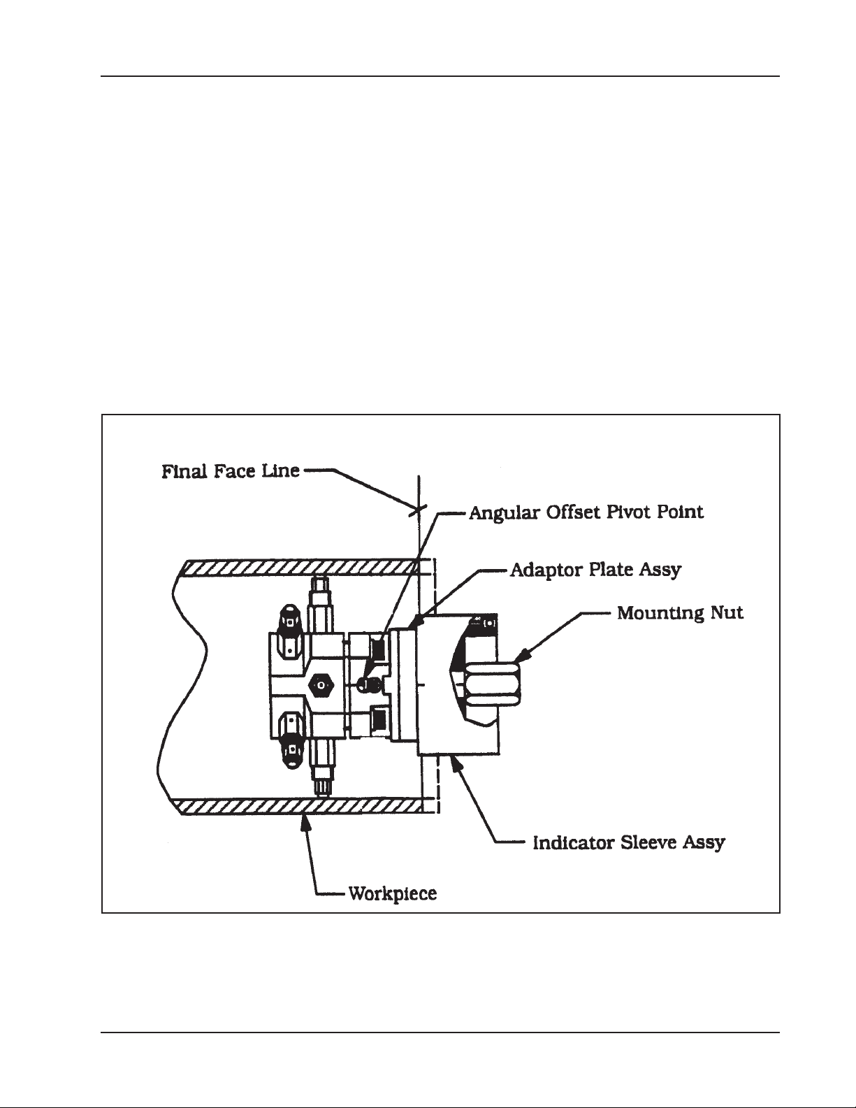
Insert the Miter Mandrel Head into the work-piece.
Installation of the Indicator Sleeve Assembly
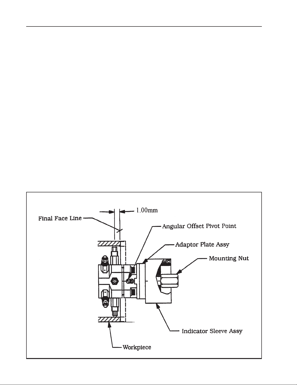
NOTE: It is highly desirable to mount the Miter Mandrel head so that Angular
Offset Pivot Point is on the same plane with the proposed finished weld
preparation.
92-0738 : Rev. 980331
15
Page 16

TRI TOOL INC.
This will diminish the amount of Parallel Offset required after the angular
adjustment has been made.
Using a tape measure or a steel ruler, keep the rear flange of the Gimbal Plate
roughly centered while turning the Jackscrews to tighten them against the ID of the
work-piece.
Use the wrenches provided to tighten all eight (8) Jackscrews securely.
Mount the Indicator Sleeve to the Adapter Plate Assembly and tighten the Mounting
Nut.
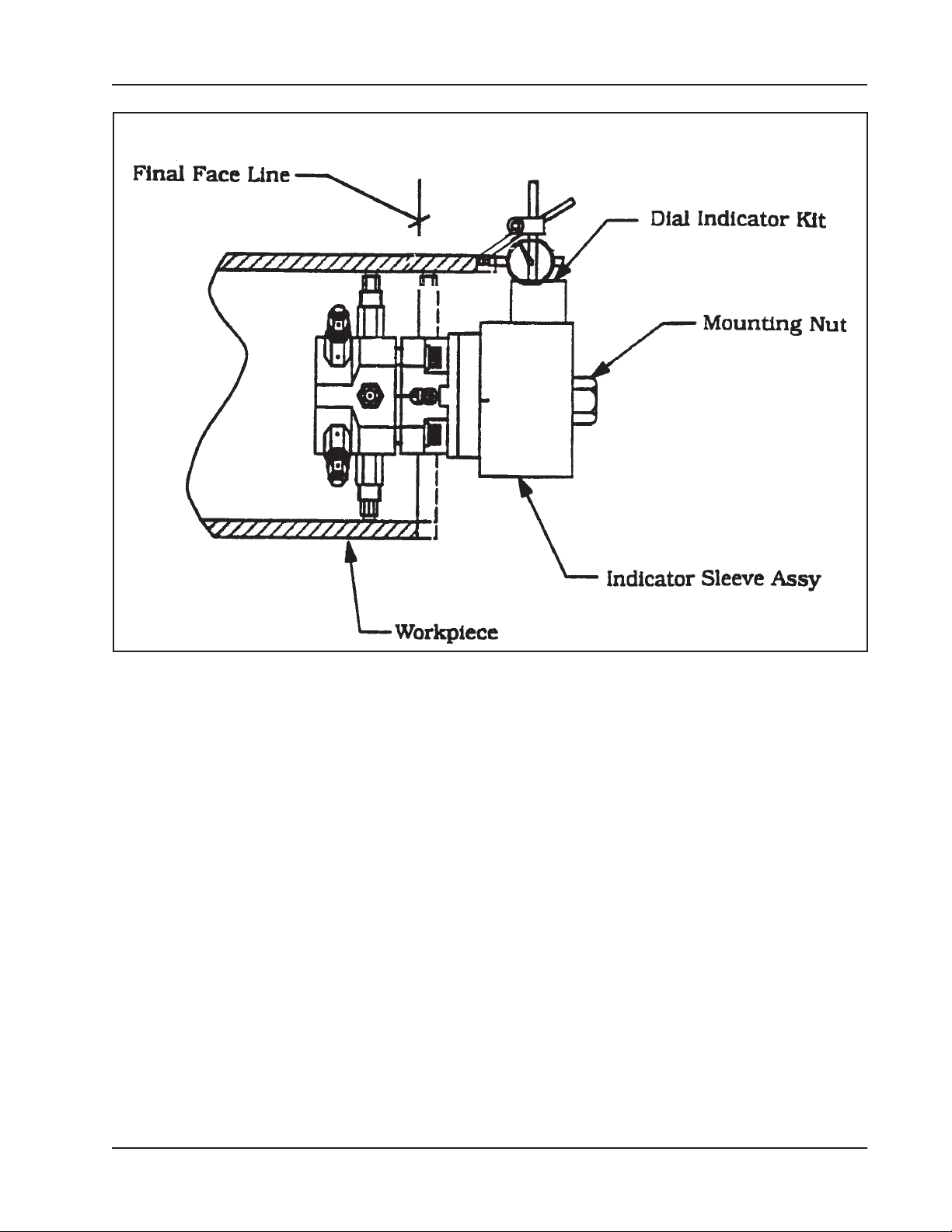
Place the magnetic based indicator holder onto the Sleeve and energize the
magnet.
If the existing surfaces of the work-piece are to be used for alignment and
centering references, use the Dial Indicator and the hardware provided.
If punch marks, scribe lines or other references are to be used, simply select
the required hardware from the Indicator Kit to be used as a pointer.
The first adjustment to be made after mounting is always the Angular Offset.
NOTE: Changing the Angular Offset will always change the Parallel Offset,
but changing the Parallel Offset will not change the Angular Offset.
To move the Adapter Plate Assembly in a given direction, one (1) or two (2) Angular
Offset Adjustment screws opposite the direction of the movement must be loosened
enough to allow the amount of movement.
Then the Screws directly across must be retighten to draw the Adapter Plate
Assembly in the desired direction.
NOTE: Never exceed 40 ft/lbs (54 N/m) of torque on the Angular offset
Adjusting Screws.
Repeat the indicating procedure and Angular Offset procedure as many times as
necessary to achieve the accuracy desired.
16
NOTE: evenly tighten all four (4) Angular Offset Adjustment Screws.
Now the parallel Offset Adjustment may be made.
92-0738 : Rev. 980331
Page 17
Dial Indicator Kit Setup
Model 212B Miter Mandrel Head for SP/FF
As before, use the Indicator Kit to determine how much the Adapter Plate Assembly
must move, and in what direction.
To move the Adapter Plate Assembly in a given direction, first loosen one or two
Parallel Offset Adjustment Screws on the side of the Adapter Plate Assembly which
you wish to move toward.
Now tighten the Screws on the side of the Adapter Plate Assembly which you wish to
move away from in order to push the Adapter Plate Assembly in a given direction.
NOTE: Never exceed 30 ft/lbs (41 N/m) of torque on the Parallel Offset
Adjustment Screws.
Repeat the indicating procedure and the Parallel Offset adjusting procedure as
many times as necessary to achieve the accuracy desired.
Once the accuracy requirements have been satisfied, evenly tighten all four (4)
Parallel Offset Adjusting Screws.
Recheck the adjustment with the Indicator Sleeve.
92-0738 : Rev. 980331
17
Page 18
TRI TOOL INC.
Remove the indicator items and the Indicator Sleeve from the Miter Head.
Tighten the Draw Nut securely.
Torque should be 50 ft/lbs (68 N/m) to 75 ft/lbs (102 N/m).
Align the torque pin holes in the end of the Mandrel Shaft with the Torque Pins in the
Adapter Plate Assembly.
Install the Mandrel Shaft Assembly onto the Adapter Plate Assembly and tighten the
Draw Rod to 75 ft/lbs (102 N/m) to 100 ft/lbs (136 N/m).
At this time the Miter Mandrel should feel absolutely tight and rigid.
Before installing the Model 212B BEVELMASTER™ be sure to read the Operator’s
Manual, giving special attention to all safety cautions and warnings.
212B Miter Mandrel, Short Perch Tool Holder Extension Adapter
In the case of a short perch mounting application, like short elbows from 8” pipe to
16” pipe, a tool holder extension adapter (P/N 27-0626 and P/N 33-2123) is used to
Installation of the Indicator Sleeve Assembly
18
92-0738 : Rev. 980331
Page 19
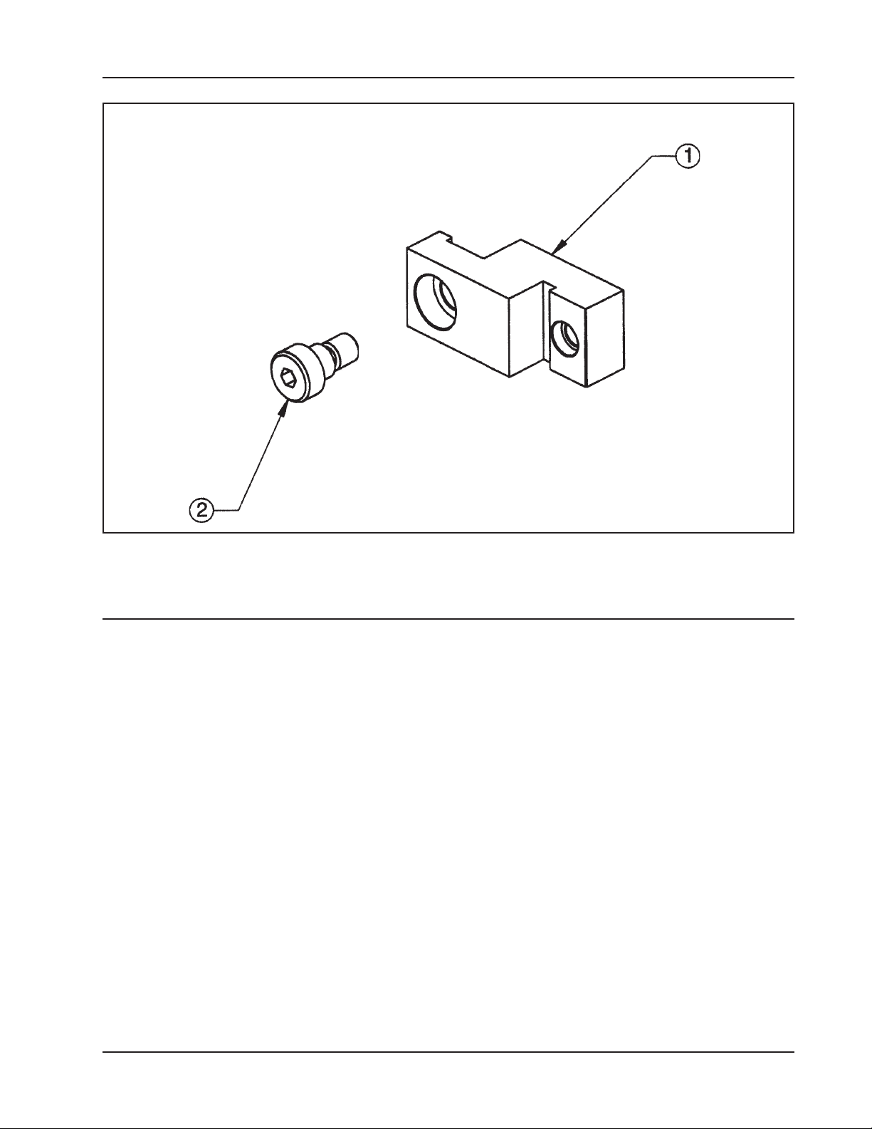
Model 212B Miter Mandrel Head for SP/FF
Short Perch Mounting, 8" to 16" Elbow Miter Mandrel , Tool Holder Extension
Item Part
No. No. Description Qty
1. 27-0626 ADAPTER, EXTENSION, TOOL HOLDER 1
2. 33-2123 SCREW, SHOULDER 1
be able to bring the miter head mounting jack screws closer to the edge of the finish
prep.
CAUTION: Do not use this extension for sizes larger then 16” pipe.
CAUTION: Do not exceed .060” (1.52 mm) chip load to avoid damage to the
tool.
The adapter No. 27-0626 is used to accommodate short perch mounting in elbows
with miter mandrel only for 16” pipe and under with load limitations.
92-0738 : Rev. 980331
19
Page 20

TRI TOOL INC.
DISASSEMBLY AND ASSEMBLY
Disassembly of the Miter Mandrel Head
Back off the four (4) Parallel Offset Adjusting Screws about three full turns each.
Unscrew the draw rod and slide the Mandrel Shaft Assembly rearward.
Remove the Draw Nut, the Adapter Plate Assembly and the Torque Plate.
Remove the four (4) Angular Offset Adjustment Screws and the four (4) Spherical
Washers.
Remove the Gimbal Plate.
Remove the Jackscrews and Spacers from the Head Assembly.
Assembly of the Miter Mandrel Head
Assembly is done in the reverse order of disassembling.
NOTE: Read the Maintenance section prior to assembling the Miter Mandrel
Head.
20
92-0738 : Rev. 980331
Page 21

Model 212B Miter Mandrel Head for SP/FF
ACCESSORIES
The following accessories are recommended for use with the Model 212B MM Head
for SP and are available from TRI TOOL INC.
Jackscrews Extension Kits:
Item Part
No. No. Description
1. 05-1425 JACKSCREW ASSEMBLY, SHORT, STAINLESS STEEL
2. 05-1426 JACKSCREW ASSEMBLY, MEDIUM, STAINLESS STEEL
3. 05-1427 JACKSCREW ASSEMBLY, LONG, STAINLESS STEEL
1
Use in place of three (3) P/N 33-1415.
2
Use in place of three (3) P/N 33-1416.
3
Use in place of three (3) P/N 33-1417.
3
1
2
92-0738 : Rev. 980331
21
Page 22
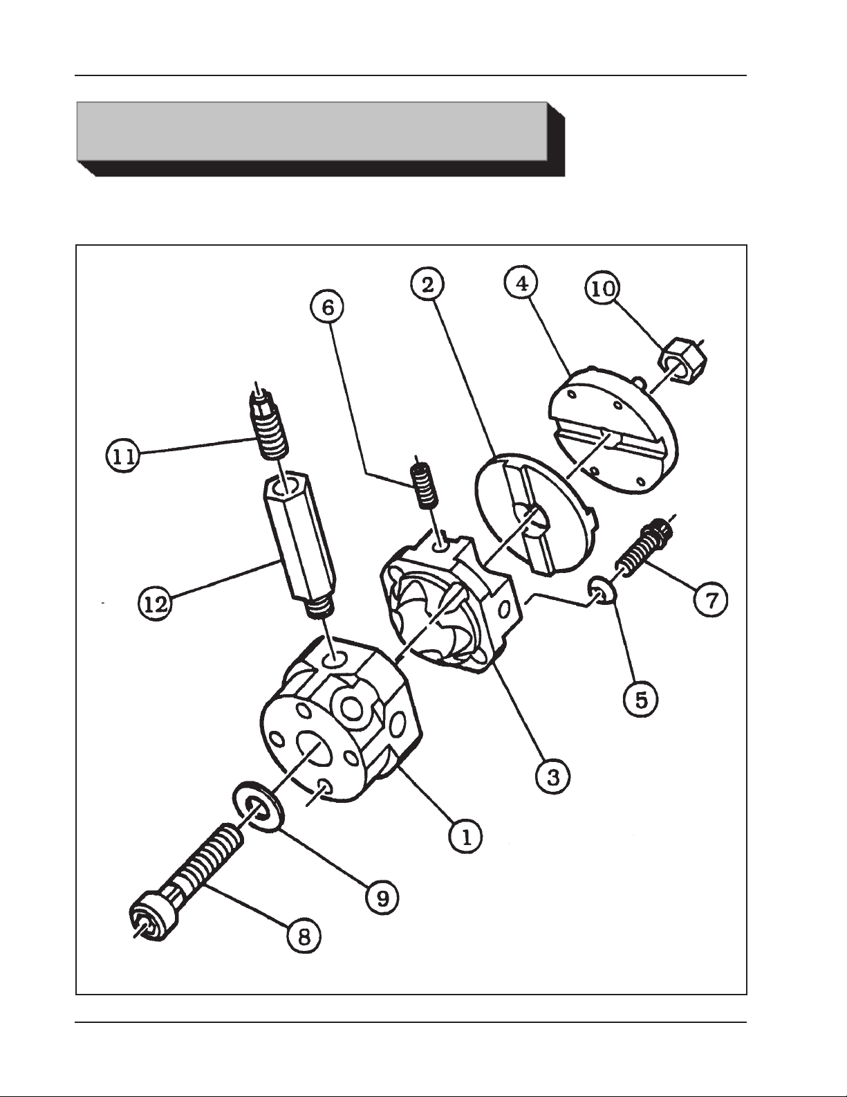
TRI TOOL INC.
ILLUSTRATED PARTS BREAKDOWN
MODEL 212B SP/FF, MITER MANDREL HEAD (P/N 06-0226)
22
92-0738 : Rev. 980331
Page 23

Model 212B Miter Mandrel Head for SP/FF
Parts List, Model 212B SP/FF, Miter Mandrel Head (P/N 06-0226)
Item Part
No. No. Description Qty
06-0226 HEAD ASSEMBLY, MITER MANDREL 1
1. 21-0101 HEAD 1
2. 24-0419 PLATE, TORQUE 1
3. 24-0456 PLATE, GIMBAL 1
4. 24-0533 PLATE ASSEMBLY, ADAPTER 1
5. 29-0152 BEARING, SPHERICAL WASHER 4
6. 33-0557 SCREW, SET 4
7. 33-1321 SCREW, HIGH-TORQUE 4
8. 33-1409 SCREW, DRAW 1
9. 34-0142 WASHER, FLAT, .75" ID 1
10. 35-0076 NUT, DRAW 1
11. 33-1415 JACKSCREW #1 8
33-1416 JACKSCREW #2 8
33-1417 JACKSCREW #3 8
12. 44-0217 SPACER #1 8
44-0218 SPACER #2 8
44-0219 SPACER #3 8
44-0220 SPACER #4 8
NOT SHOWN
86-0087 CASE 1
05-1174 WRENCH KIT 1
36-0010 WRENCH, L, 1/4" HEX
36-0059 WRENCH, COMBO, 1 1/4"
36-0060 WRENCH, COMBO, 1 1/8"
36-0076 WRENCH, COMBO, 9/16"
36-0121 WRENCH, COMBO, 1/2"
92-0738 : Rev. 980331
23
Page 24
TRI TOOL INC.
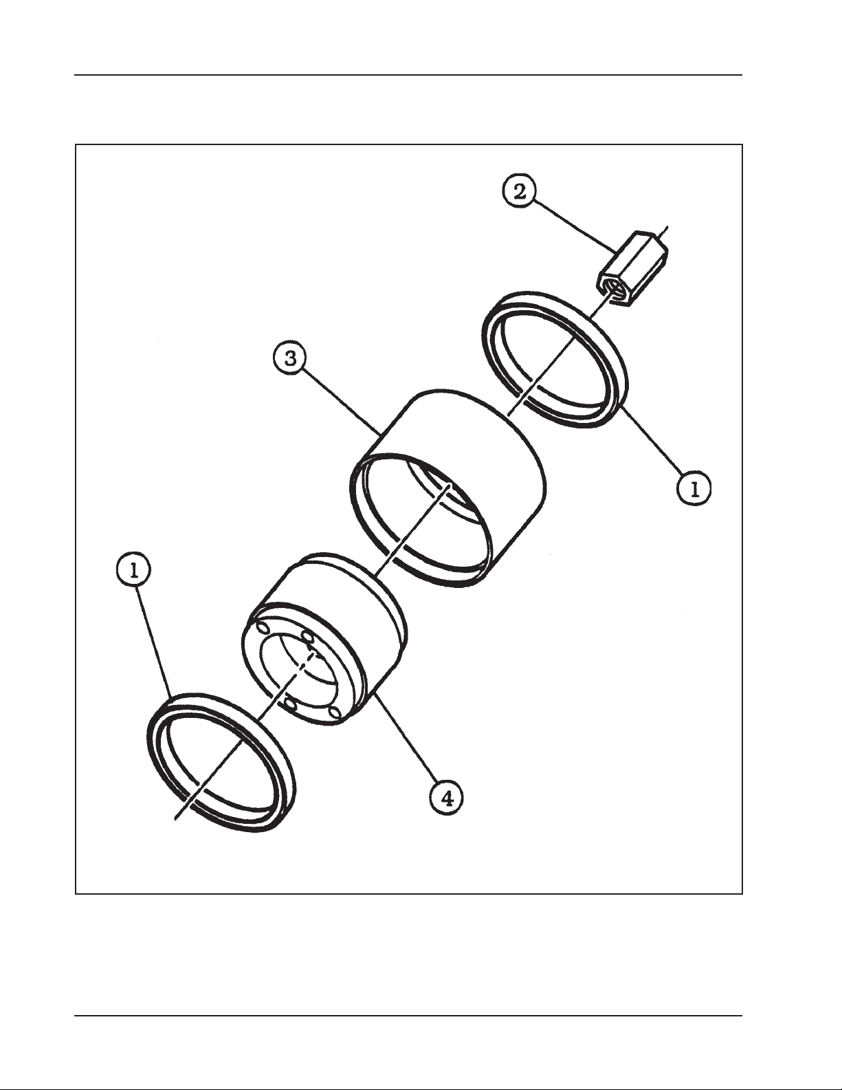
INDICATOR SLEEVE ASSEMBLY (P/N 46-0128)
24
92-0738 : Rev. 980331
Page 25

Model 212B Miter Mandrel Head for SP/FF
Parts List, Sleeve Assembly, Indicator (P/N 46-0128)
Item Part
No. No. Description Qty
1. 29-0102 BEARING, BALL 2
2. 35-0222 NUT, LONG 1
3. 46-0126 SLEEVE, OUTER 1
4. 46-0127 SLEEVE, INNER 1
92-0738 : Rev. 980331
25
Page 26
TRI TOOL INC.
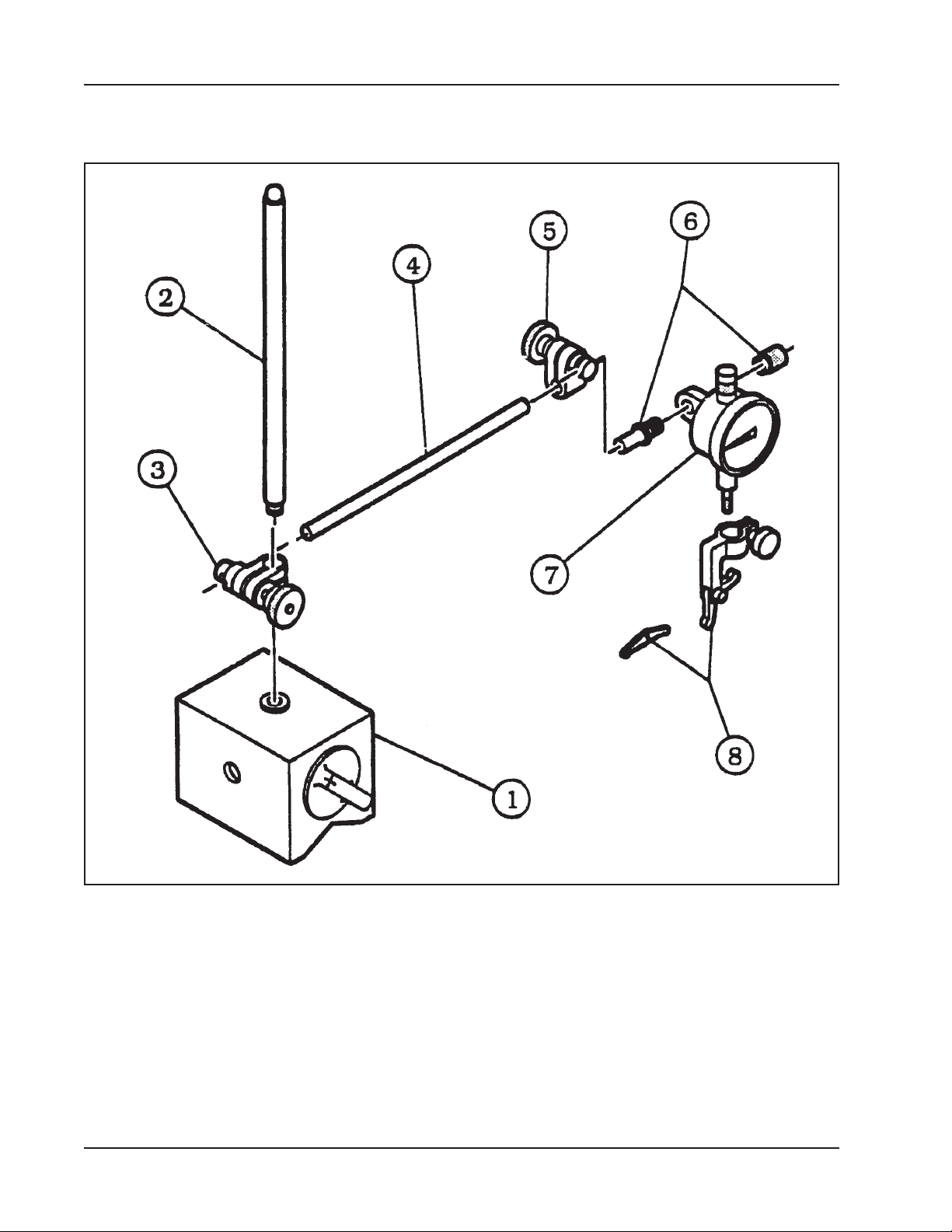
DIAL INDICATOR ASSEMBLY (P/N 50-0015)
26
92-0738 : Rev. 980331
Page 27

Model 212B Miter Mandrel Head for SP/FF
Parts List, Dial Indicator Assembly (P/N 50-0015)
Item Part
No. No. Description Qty
1. 30-0334 BASE, MAGNETIC 1
2. 30-0335 POST, UPRIGHT 1
3. 30-0336 SLEEVE 1
4. 30-0337 ROD 1
5. 30-0338 SLEEVE 1
6. 30-0339 ATTACHMENT, INDICATOR 1
7. 30-0340 INDICATOR, DIAL 1
8. 30-0341 ATTACHMENT, UNIVERSAL 1
92-0738 : Rev. 980331
27
Page 28
TRI TOOL INC.
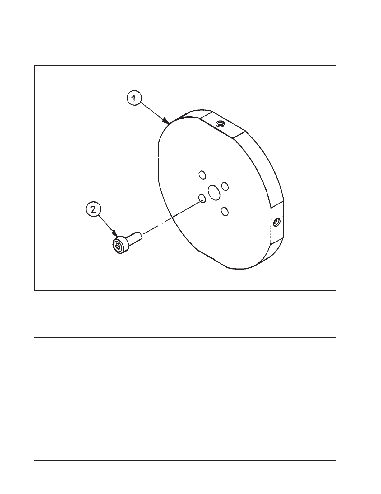
EXTENSION PLATE KIT (P/N 05-1219)
Parts List, Extension Plate Kit (P/N 05-1219)
Item Part
No. No. Description Qty
1. 24-0608 EXTENSION PLATE 1
2. 33-1456 SCREW, CAP, 1/2-20 X 1.75" 4
NOT SHOWN
36-0012 WRENCH, L 3/8" HEX 1
28
92-0738 : Rev. 980331
 Loading...