


18-HD64D1-1
ComfortLink™ II Installation Guide
Other Installation Guides may be necessary, based on system configuration.
A complete list of other optional components is shown below.
1 |
Thermostat |
|
2 |
Relay Panel |
|
For use with 24V indoor systems (optional) |
||
|
||
|
|
|
3 |
Zone Panel (optional) |
|
4 |
Zone Sensor with Display (optional) |
|
5 |
Zone Sensor (optional) |
|
6 |
Zone Dampers (optional) |
TZONE950AC52ZA
ALL phases of this installation must comply with NATIONAL, STATE AND LOCAL CODES
IMPORTANT — This Document is customer property and is to remain with this unit.
These instructions do not cover all variations in systems or provide for every possible contingency to be met in connection with the installation. Should further information be desired or should particular problems arise which are not covered sufficiently for the purchaser’s purposes, the matter should be referred to your installing dealer or local distributor.
Section 1. Safety
▲! WARNING
This information is intended for use by individuals possessing adequate backgrounds of electrical and mechanical experience. Any attempt to repair a central air conditioning product may result in personal injury and/or property damage. The manufacturer or seller cannot be responsible for the interpretation of this information, nor can it assume any liability in connection with its use.
▲! WARNING
LIVE ELECTRICAL COMPONENTS!
During installation, testing, servicing, and troubleshooting of this product, it may be necessary to work with live electrical components. Failure to follow all electrical safety precautions when exposed to live electrical components could result in death or serious injury.
Table of Contents |
|
Section 1. Safety................................................. |
1 |
Section 2. General Information......................... |
2 |
Section 3. Physical Installation......................... |
5 |
Section 4. Wiring................................................ |
7 |
Section 5. Installer Setup................................... |
9 |
Section 6. Advanced Features........................ |
13 |
Section 7. Troubleshooting.............................. |
17 |
Section 8. Installer Setup Parameters............ |
18 |
NOTE: See the User’s Guide for |
|
wireless setup information. |
|
|
03/11 |
Section 2. General Information
2.1 Overview
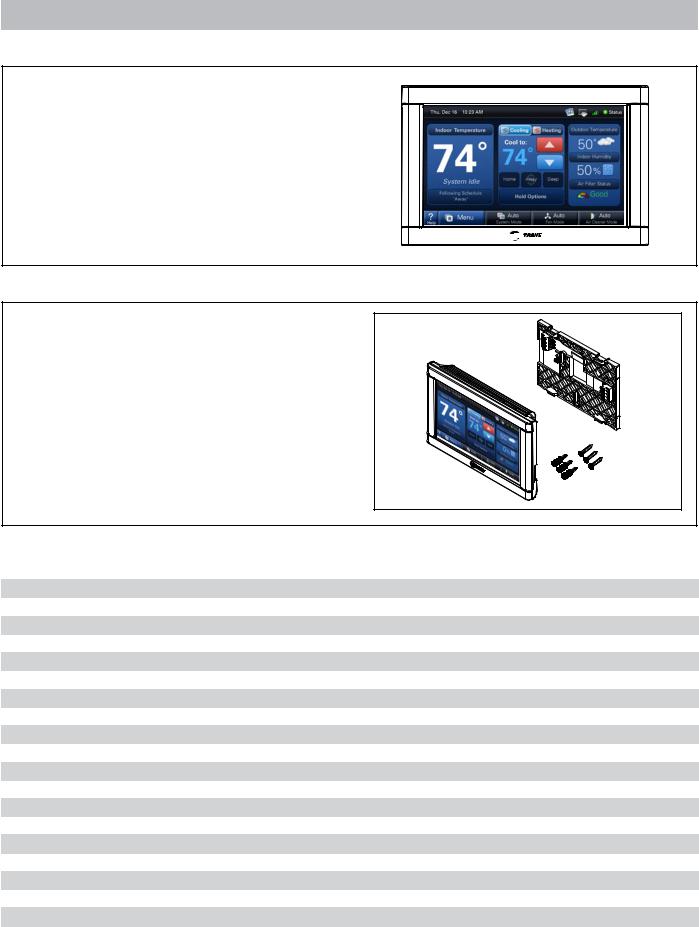
The ComfortLink II Thermostat is a Communicating 7-inch color touch screen that provides an easy-to- use interface to the end user.
The thermostat is a communicating wall mounted control that allows a user to control an HVAC and zoning system.
With the addition of the 24VAC Relay Panel, conventional HVAC systems can also be controlled and zoned.
2.2 Contents in Box
The following parts are included in product model
TZONE950AC52ZA:
1 - Thermostat
1 - Sub-Base
3 - SnapSkru® Wall Achors
3 - 1” Screws
2.3 Specifications
Specification |
|
Description |
|
|
|
Product Model: |
|
TZONE950AC52ZA |
|
|
|
Product: |
|
ComfortLink II Thermostat |
|
|
|
Size: |
|
7.3” width x 4.3” height x 1.2” depth |
|
|
|
Storage Temperature |
|
-40°F to 175°F, 5% to 95% RH non-condensing |
|
|
|
Operating Temperature: |
|
25°F to 126°F, 5% to 90% RH non-condensing |
|
|
|
Input Power: |
|
24 VAC from HVAC System (Range: 18-32 VAC) |
|
|
|
Power Consumption: |
|
7 VA* |
|
|
|
Wire usage: |
|
Minimum 18 gauge NEC approved control wiring |
|
|
|
Zone Sensor Wireless Range |
(802.15.4): |
60 ft. through 3 standard walls |
|
|
|
Wireless Connectivity Range |
(802.11 b/g): |
Varies with router model and placement |
|
|
|
Communications: |
|
ComfortLink II - 3 wire connection |
|
|
|
System Modes: |
|
Heat, Cool, Auto, Emergency Heat |
|
|
|
Fan Modes: |
|
On, Auto, Circulate |
|
|
|
Cooling Setpoint Temperature Range: |
60°F to 99°F, 1°F resolution |
|
|
|
|
Heating Setpoint Temperature Range: |
55°F to 90°F, 1°F resolution |
|
|
|
|
Indoor Temperature Display Range: |
20°F to 119°F |
|
|
|
|
Outdoor Temperature Display Range: |
-31°F to 119°F |
|
|
|
|
Indoor Humidity Display Range: |
0% to 99%, 1% resolution |
|
|
|
|
Minimum Cycle Off Time Delay: |
Compressor: 5 minutes, Heat: 1 minute |
|
|
|
|
*On every application, 24VAC loads should be reviewed to be sure the indoor unit control power transformer is adequately sized. See the Relay Panel Installer’s Guide for guidelines.
2 |
18-HD64D1-1 |
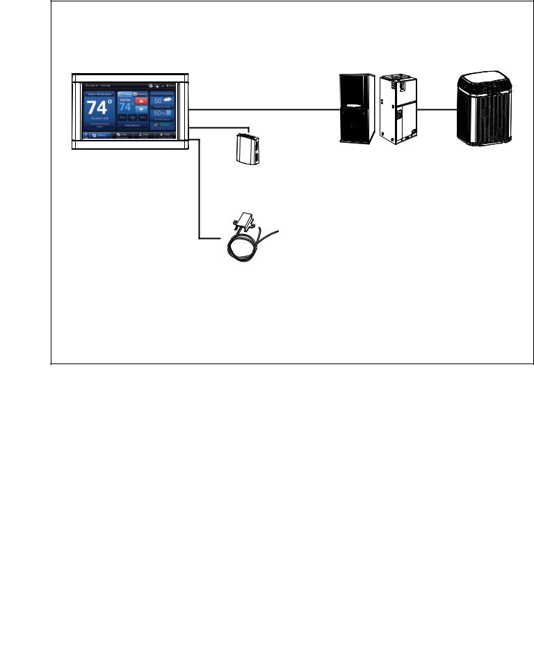
2.4 ComfortLink II System Connections
Communicating System |
|
|
|
Thermostat |
Indoor Unit |
Outdoor Unit |
|
TZONE950AC52ZA |
|||
|
|
||
Wired Remote |
|
|
|
Sensor* |
|
|
|
ZZSENSAL0400AA |
|
|
|
Wired Remote |
|
|
|
Outdoor Sensor* |
|
|
|
BAYSEN01ATEMPA |
|
|
|
*Optional |
|
|
18-HD64D1-1 |
3 |

2.4 ComfortLink II System Connections (Continued)
24V System |
|
|
|
|
|
Relay Panel |
|
Thermostat |
|
Relay Panel |
Indoor Unit |
TZONE950AC52ZA |
|
BAY24VRPAC52DA |
|
Wired Remote |
|
||
|
|
|
|
|
Sensor* |
|
|
|
ZZSENSAL0400AA |
|
|
|
Wired Remote |
|
Outdoor Unit |
|
|
|
|
|
Outdoor Sensor |
|
|
|
BAYSEN01ATEMPA |
|
|
*Optional |
|
|
|
4 |
18-HD64D1-1 |

Section 3. Physical Installation
1A Temperature Sensing Considerations
The thermostat sensor is designed for installation in climate controlled living spaces. It is recommended to place the sensor in central locations with good circulation. Avoid exterior walls and areas near windows, doors, vents or concealed pipes or chimneys.
YES |
NO |
NO |
|
5 FEET |
|
[1.5 METERS] |
|
1B |
Wireless Reception Considerations |
|
|
|
|
||
If enabling wireless, choose a mounting location that ensures adequate signal strength. |
|
|
|
|
|
||
A wireless device may have significantly different signal strengths if its position chang- |
|
|
|
es relative to other wireless devices. If the thermostat shows poor signal strength, you |
|
|
|
may be able to improve the signal strength by moving the thermostat a short distance |
Wireless |
|
|
in any direction. |
|
|
|
|
|
||
Considerations to Maximize Signal Strength: |
|
|
|
•Do not mount the thermostat more than 30 feet from the wireless router (through no more than three interior walls).
•Do not mount the thermostat in areas where electromagnetic emissions from other devices, appliances or wiring can interfere with the thermostat’s communication. (i.e. wireless phones, security systems, wireless internet cameras)
•Do not mount the thermostat in recessed areas, near metal objects, or near structures. (i.e. doors, appliances, entertainment centers or shelving units)
•Do not mount the thermostat closer than 2 inches to any pipes, duct work, or other metal obstructions.
•Do not have metal obstructions, concrete or brick walls between the thermostat and the wireless router it will be connected to.
NOTE: See the User’s Guide for wireless setup information (weather, multi-system and remote software update functionality).
2 Removing Sub-Base Wall Plate
Remove sub-base plate from the thermostat by inserting a small flat blade screwdriver into the notch at each of the four tabs as shown.
Gently pry the sub-base away from the the thermostat.
NOTE: This tight fit is normal and ensures that the thermostat is held securely to the sub-base when mounted on the wall.
18-HD64D1-1 |
5 |

3 Mounting Sub-Base to Wall
Be sure wires are routed through the center of the base plate and are long enough to connect to terminals.
Select and mark three holes.
NOTE: The three hole locations indicated at right are recommended. The top location is an optional mounting screw location.
A level may be used to ensure professional appearance.
Optional Hole |
Three (3) |
Recommended |
Screw |
Locations |
4A Mounting to Studs
Attach base to wall using 3 screws provided. The locations indicated provide the most secure mounting and are recommended.
NOTE: Since moderate force is required when removing the thermostat from the sub-base, the subbase must be securely attached to the wall.
Do not overtighten screws to avoid damaging the sub-base.
4B Mounting to Drywall
If mounting to drywall, supplied SnapSkru® connectors must be used to mount the thermostat sub-base to the wall. These connectors will ensure that the control is adequately supported.
NOTE: Since moderate force is required when removing the thermostat from the sub-base, a firmly mounted sub-base is essential.
1) Press tip of SnapSkru® anchor into drywall using #2 Phillips screwdriver or screw gun. Drive anchor clockwise into drywall until anchor stops flush with wall.
2) Place sub-base over anchor and insert screw.
3) Tighten screw flush with subbase. Screw “pops” open anchor, locking anchor on wall.
Do not overtighten screws to avoid damaging the sub-base.
6 |
18-HD64D1-1 |
 Loading...