


 Loading...
TD-8841 User Guide
ADSL2+ Modem Router
Rev: 2.0.1
1910010193
COPYRIGHT & TRADEMARKS
Specifications are subject to change without notice.  is a registered trademark of TP-LINK TECHNOLOGIES CO., LTD. Other brands and product names are trademarks or registered trademarks of their respective holders.
No part of the specifications may be reproduced in any form or by any means or used to make any derivative such as translation, transformation, or adaptation without permission from TP-LINK TECHNOLOGIES CO., LTD. Copyright © 2009 TP-LINK TECHNOLOGIES CO., LTD.
All rights reserved.
http://www.tp-link.com
I

FCC STATEMENT
This equipment has been tested and found to comply with the limits for a Class B digital device, pursuant to part 15 of the FCC Rules. These limits are designed to provide reasonable protection against harmful interference in a residential installation. This equipment generates, uses and can radiate radio frequency energy and, if not installed and used in accordance with the instructions, may cause harmful interference to radio communications. However, there is no guarantee that interference will not occur in a particular installation. If this equipment does cause harmful interference to radio or television reception, which can be determined by turning the equipment off and on, the user is encouraged to try to correct the interference by one or more of the following measures:
•Reorient or relocate the receiving antenna.
•Increase the separation between the equipment and receiver.
•Connect the equipment into an outlet on a circuit different from that to which the receiver is connected.
•Consult the dealer or an experienced radio/ TV technician for help.
This device complies with part 15 of the FCC Rules. Operation is subject to the following two conditions:
1)This device may not cause harmful interference.
2)This device must accept any interference received, including interference that may cause undesired operation.
Any changes or modifications not expressly approved by the party responsible for compliance could void the user’s authority to operate the equipment.
CE Mark Warning
This is a class B product. In a domestic environment, this product may cause radio interference, in which case the user may be required to take adequate measures.
II
EC DECLARATION OF CONFORMITY (EUROPE)
In compliance with the EMC Directive 89/336/EEC, Low Voltage Directive 73/23/EEC, this product meets the requirements of the following standards:
•EN55022
•EN55024
•EN60950
SAFETY NOTICES
Caution:
Do not use this product near water, for example, in a wet basement or near a swimming pool.
III
|
|
CONTENTS |
|
Package Contents .................................................................................................... |
1 |
||
Chapter 1. |
Introduction ........................................................................................ |
2 |
|
1.1 |
Product Overview...................................................................................................... |
2 |
|
1.2 |
Main Features ........................................................................................................... |
2 |
|
1.3 |
Supporting Protocol................................................................................................... |
3 |
|
1.4 |
Transmit Data-rate .................................................................................................... |
3 |
|
1.5 |
ATM Property ............................................................................................................ |
3 |
|
1.6 |
System Support......................................................................................................... |
4 |
|
1.7 |
Working Environment................................................................................................ |
4 |
|
1.8 |
Conventions .............................................................................................................. |
2 |
|
Chapter 2. Hardware Installation Guide.............................................................. |
5 |
||
2.1 |
System Requirement................................................................................................. |
5 |
|
2.2 |
The Front Panel ........................................................................................................ |
5 |
|
2.3 |
The Rear Panel ......................................................................................................... |
6 |
|
2.4 |
Environment Requirements....................................................................................... |
6 |
|
2.5 |
Hardware Installation Procedures ............................................................................. |
6 |
|
Chapter 3. Quick Installation Guide .................................................................... |
8 |
||
3.1 |
Configure PC............................................................................................................. |
8 |
|
3.2 |
USB Configuration .................................................................................................. |
11 |
|
3.3 |
Login ....................................................................................................................... |
13 |
|
3.4 |
Quick Setup............................................................................................................. |
14 |
|
|
3.4.1 |
PPPoA............................................................................................................................ |
15 |
|
3.4.2 |
PPPoE............................................................................................................................ |
16 |
|
3.4.3 |
MER................................................................................................................................ |
18 |
|
3.4.4 |
IPoA................................................................................................................................ |
19 |
|
3.4.5 |
Bridging .......................................................................................................................... |
20 |
Chapter 4. |
Software Configuration.................................................................... |
22 |
|
4.1 |
Device Info .............................................................................................................. |
22 |
|
4.2 |
Quick Setup............................................................................................................. |
22 |
|
4.3 |
Advanced Setup...................................................................................................... |
22 |
|
|
4.3.1 |
WAN ............................................................................................................................... |
23 |
|
4.3.2 |
LAN................................................................................................................................. |
34 |
|
4.3.3 |
MAC Clone ..................................................................................................................... |
37 |
|
4.3.4 |
Security........................................................................................................................... |
38 |
IV
|
4.3.5 |
Routing ........................................................................................................................... |
41 |
|
4.3.6 |
DSL................................................................................................................................. |
43 |
4.4 |
Diagnostics.............................................................................................................. |
45 |
|
4.5 |
Management ........................................................................................................... |
46 |
|
|
4.5.1 |
Settings........................................................................................................................... |
46 |
|
4.5.2 |
System Log .................................................................................................................... |
48 |
|
4.5.3 |
SNMP Agent................................................................................................................... |
49 |
|
4.5.4 |
Access Control ............................................................................................................... |
50 |
|
4.5.5 |
Update Firmware............................................................................................................ |
52 |
|
4.5.6 |
Save/Reboot................................................................................................................... |
53 |
Chapter 5. |
Software Dial..................................................................................... |
54 |
|
Appendix A: FAQ.................................................................................................... |
56 |
||
Appendix B: Default Configuration....................................................................... |
58 |
||
V

TD-8841 ADSL2+ Modem Router User Guide
Package Contents
The following items should be found in your package:
¾One TD-8841 ADSL2+ Modem Router
¾One AC power Adapter for TD-8841 ADSL2+ Modem Router
¾One Resource CD for TD-8841 ADSL2+ Modem Router, including:
•This Guide
•Other Helpful Information
•Quick installation Guide Program
¾Quick installation Guide
¾One RJ45 cable
¾Two RJ11 cables
¾One ADSL splitter
) Note:
Make sure that the package contains the above items. If any of the listed items are damaged or missing, please contact with your distributor.
1

TD-8841 ADSL2+ Modem Router User Guide
Chapter 1.Introduction
Thank you for choosing the TD-8841 ADSL2+ Modem Router.
1.1Product Overview
With the excellent circuit design and high quality production, we guarantee the ADSL2+ Modem Router’s high performance, great stability and easy to use.
The TD-8841 uses integrated ADSL2+ transceiver. The AFE supports full-rate ADSL connectivity conforming to the ITU and ANSI specifications.
In addition to the basic DMT physical layer functions, the ADSL PHY supports dual latency ADSL framing (fast and interleaved) and the I.432 ATM Physical Layer.
The TD-8841 is a complete plug-and-play solution. With standard Ethernet interface, it can be directly connected to any 10M/100M Ethernet devices, and support Auto-MDIX.
The TD-8841 uses not only html (web mode through Ethernet port) but also external utility software to configure the Router. You can download it from our website (http://www.tp-link.com).
1.2Conventions
The Router or TD-8841, or device mentioned in this User guide stands for TD-8841 ADSL2+ Modem Router without any explanations.
Parameters provided in the pictures are just references for setting up the product, which may differ from the actual situation.
You can set the parameters according to your demand.
) Note:
The two devices of TD-8841 and TD-8841B are sharing this User Guide. For simplicity, we will take TD-8841 for example throughout this Guide.
1.3Main Features
¾High speed and asymmetry data transmit mode, built-in 4-port switch realize multi-user to share wide-band internet access
¾Supports All ADSL2+ industrial standards
¾Compatible with all mainstream DSLAM (CO)
¾Firmware upgradeable
¾Provides integrated access of internet and route function which face to SOHO user
2

TD-8841 ADSL2+ Modem Router User Guide
¾Advanced DMT modulation and demodulation
¾Real-time Configuration and device monitoring
¾Quick response semi-conductive surge protect circuit, provides reliable ESD and surge-protect function
1.4Supporting Protocol
-G.992.1 (G.dmt) - Annex A/B/C
-G.992.2 (G.lite) - Annex A/B/C
-ANSI T1.413
-G.992.3 (ADSL2) - Annex A/B/C/M and Annex L (RE-DSL) compliant
-G.992.5 (ADSL2+) Annex A/B/C and Annex L (RE-DSL) compliant
-ADSL dual latency (fast path and interleaved path)
-I.432 ATM physical layer compliant
-Supports RFC2364 (PPPoA)
-Supports RFC2516 (PPPoE)
-Supports RFC1483 (EoA) (Bridged *and Router)
-Supports RFC1577 (IPoA)
) Note:
“*” Needs the third-party software.
1.5Transmit Data-rate
¾Max download data-rate: 24Mbps
¾Max upload data-rate: 3.5Mbps
¾Max line length: 6Km
1.6ATM Property
¾AAL0, AAL5, OAM, RM, and raw cell types supported
¾Direct hardware support for 4 Receive VCs, with additional RX VCs and TX VCs supported in software
¾Full 24-bit Virtual Path Identifier (VPI) and Virtual Circuit Identifier (VCI)
3

TD-8841 ADSL2+ Modem Router User Guide
1.7System Support
¾Support PVC
¾Support NAT DHCP and so on
¾Support IEEE 802.3 IEEE 802.3u
¾Support 10Base-T/100BASE-TX full-duplex or half duplex Ethernet
¾Support Auto-MDIX
1.8Working Environment
¾Operating temperature: 0 ~40
¾Storage temperature: -40 ~70
¾Working Humidity: 10%~90% RH (non-condensing)
¾Storage Humidity: 5%~90% RH (non-condensing)
4
TD-8841 ADSL2+ Modem Router User Guide
Chapter 2.Hardware Installation Guide
The TD-8841 maintains five separate interfaces: four Ethernet and one ADSL interface. The Router should not be located where it will be exposed to moisture or excessive heat. Place the Router in a location where it can be safely connected to the various devices. The electrical outlet shall be installed near the device and shall be easily accessible.
2.1 System Requirement
Confirm your computer has been installed with networking interface card (NIC) before connecting ADSL2+ Modem Router to your computer, with the operating system supporting the TCP/IP protocol.
2.2 The Front Panel
The front panel of ADSL2+ Modem Router includes one power indicator and seven function indicators, as explained in chart below.
LED Explanation
Name |
Status |
Indication |
|
|
|
|
|
Power |
On |
Power is on. |
|
|
|
||
Off |
Power is off. |
||
|
|||
|
|
|
|
|
On |
The LINE port is linked up. |
|
ADSL |
Flash |
The ADSL negotiation is in progress. |
|
|
Off |
The LINE port is linked down. |
|
|
|
|
|
|
On |
A successful PPP connection has been built. |
|
|
|
|
|
Internet |
Flash |
Data is being transferred over the Internet. |
|
|
|
||
|
Off |
There is no successful PPP connection or the Router works on |
|
|
Bridge mode. |
||
|
|
||
|
|
|
|
|
On |
There is a successful connection on USB port but no activity. |
|
|
|
|
|
USB |
Off |
There is no connection on USB port or the connection is abnormal. |
|
|
|
|
|
|
Flash |
Data is being transferred over the USB connection. |
|
|
|
|
|
|
On |
There is a successful connection on the corresponding 1~4 (LAN) |
|
|
port but no activity. |
||
|
|
||
|
|
|
|
1~4 (LAN) |
Off |
There is no connection on the corresponding 1~4 (LAN) port or the |
|
|
connection is abnormal. |
||
|
|
||
|
Flash |
Data is being transferred over the 1~4 (LAN) port. |
|
|
|
|
5
TD-8841 ADSL2+ Modem Router User Guide
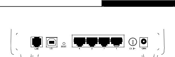
2.3The Rear Panel
¾ON/OFF: Turn on/off the ADSL2+ Modem Router’s power.
¾POWER: Please do not use any unknown power adapter; otherwise your ADSL2+ Modem Router may be damaged.
¾RESET (reset default): With the Router powered on, use a pin to press and hold the Reset button for at least 5 seconds. And then release the button and wait the Router to reboot to its factory default settings.
¾1~4(LAN): Connect with your computer’s NIC.
¾LINE (WAN): Connect to the MODEM Port of Splitter or connect to the telephone line port.
2.4Environment Requirements
¾Place your Router on the flat and stable platform.
¾Place your Router in a well ventilated place far from direct sunlight, any heater or heating vent.
¾Leave at least 2 inches (5cm) space around the device for heat dissipation.
¾Keep your Router away from appliances with a strong electric field or magnetic field, such as a microwave oven or refrigerator.
¾Turn off your Router and unplug the power adapter in a lighting storm to avoid damage.
¾The electrical outlet shall be installed near the device and shall be easily accessible.
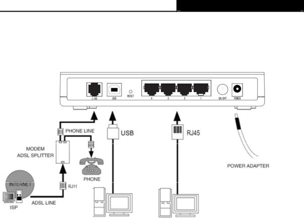
2.5Hardware Installation Procedures
Before connecting the Router to your computer, make sure your broadband service provided by your ISP is available. Cut off the power supply and keep your hands dry. The procedure to connect the Router can be described in the following steps.
First Step: Connect the MODEM port of Splitter with the TD-8841 ADSL2+ Modem Router’s LINE port by telephone line. If you need to use a telephone, please attach telephone line into the phone port of Splitter.
Second Step: Connect category 5 cable with RJ45 jacks to the Router’s LAN port and your computer’s NIC.
6
TD-8841 ADSL2+ Modem Router User Guide
Third Step: Plug one end of the AC Power Adapter into the Power jack on the Router and the other end to a standard electrical outlet.
Last Step: Check the line connection to see if everything is ready. Power up finally.
Figure 2-1
7
TD-8841 ADSL2+ Modem Router User Guide
Chapter 3.Quick Installation Guide
3.1Configure PC
After you directly connect your PC to the TD-8841 or connect your adapter to a Hub/Switch which has connected to the Router, you need to configure your PC’s IP address. Now you have two ways to configure the TCP/IP protocol below:
¾ Setting IP address automatically
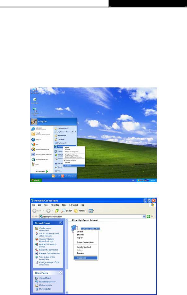
Step 1: Click the Start menu on your desktop, right click My Network Places, and then select Properties (shown in Figure 3-1).
Figure 3-1
Step 2: Right click Local Area Connection (LAN), and then select Properties.
Figure 3-2
8

TD-8841 ADSL2+ Modem Router User Guide
Step 3: Select General tab, highlight Internet Protocol (TCP/IP), and then click the Properties button.
Figure 3-3
Step 4: Select “Obtain an IP address automatically” and “Obtain DNS server address automatically” in the screen below. And then click OK.
Figure 3-4
9
TD-8841 ADSL2+ Modem Router User Guide
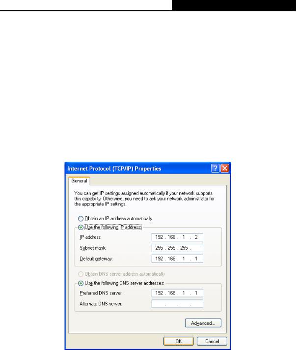
¾ Setting IP address manually
The default IP address of the ADSL2+ Modem Router is 192.168.1.1, and the default Subnet Mask is 255.255.255.0. These values can be seen from the LAN, and can be changed as your desire. As an example, we use the default values for description in this guide.
Step 1: Select Use the following IP address radio button in the next screen.
Step 2: Enter the IP address as 192.168.1.* (* is any value between 2 to 254). The Subnet mask is 255.255.255.0. Then type the ADSL Router’s LAN IP address 192.168.1.1 into the Default gateway field.
Step 3: Select Use the following DNS server addresses radio button. In the Preferred DNS Server field you can enter the same value as the Default gateway or type the local DNS server IP address.
Figure 3-5
) Note:
1)Users of Windows 98 can open TCP/IP Properties according to the following: Right-click (Mouse) Network Neighbor Æ Choose Properties -Æ Double-click TCP/IP.
2)Users of Windows 2000/NT/XP can do the following: Right-click Network Neighbor Æ Choose Properties Æ Right-click Local Connection Æ Choose Properties Æ Double-click
Internet Protocol (TCP/IP).
3)The words in fact may be different with this guide.
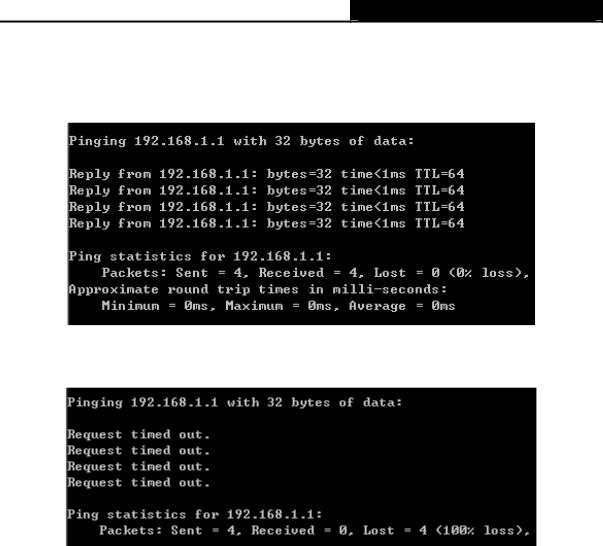
Now, you can run the Ping command in the command prompt to verify the network connection.
10
TD-8841 ADSL2+ Modem Router User Guide
Please click the Start menu on your desktop, select Run tab, type cmd in the field, and then type ping 192.168.1.1 on the next screen, and then press Enter.
If the screen looks like the following, you have been successful.
Figure 3-6
If the screen looks like the following, the connection has failed. Please try again.
Figure 3-7
3.2USB Configuration
If you use the USB interface, you must install the USB’s driver to the computer first. You can obtain the drivers from the provided CD, or download from our website. (http://www.tp-link.com)
USB Drive installation procedures
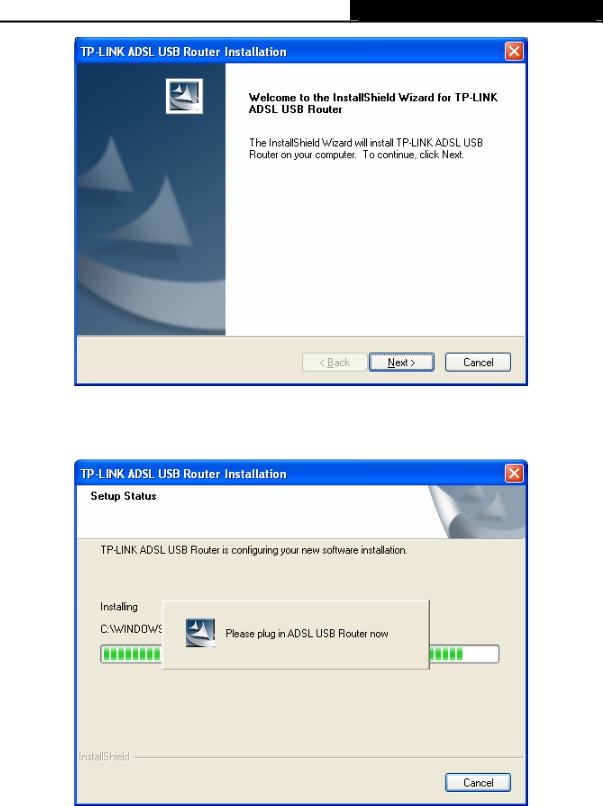
Step 1: Please connect your PC to the Router through the USB port at first, then open the relative operating system folder in the CD, and double click Setup.exe to install the USB driver.
Step 2: Soon, Figure 3-8 will display after a moment. Click Next to continue.
11
TD-8841 ADSL2+ Modem Router User Guide
Figure 3-8
Step 3: You will see Figure 3-9 as follow, please wait a moment.
Figure 3-9
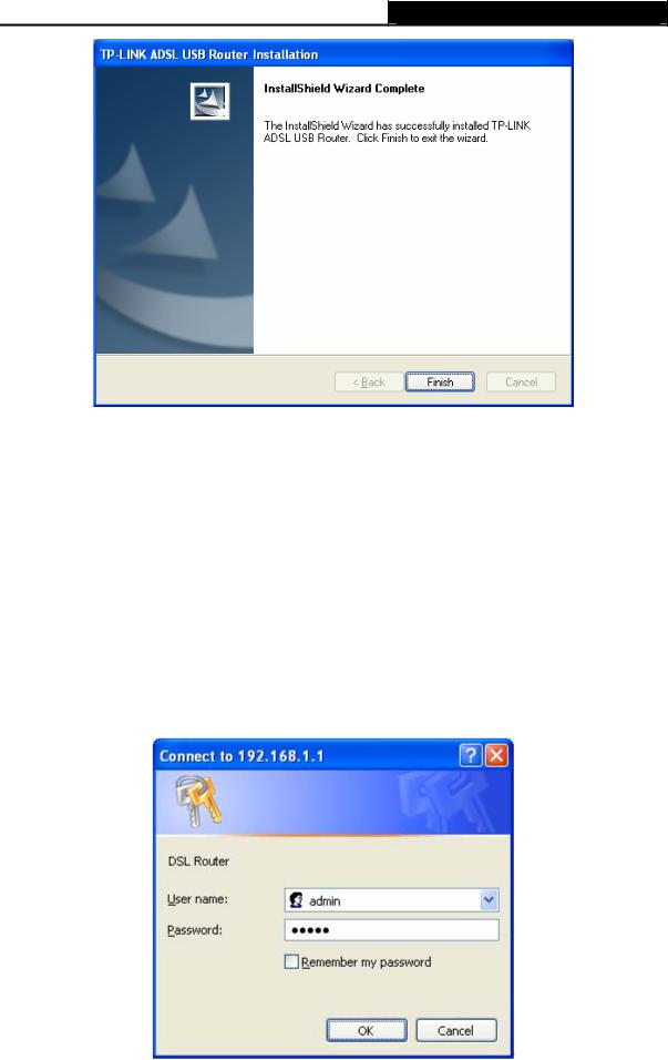
Step 4: After that, you will see Figure 3-10. Click Finish to complete the installation.
12
TD-8841 ADSL2+ Modem Router User Guide
Figure 3-10
) Note:
1)All of the above settings are under windows XP.
2)If you want to pull out the USB device you must disconnect the network of USB first.
3)In the Vista operating system, maybe the “Unknown Device” screen will pop up when you insert the USB cable of the Router to a computer, please just unplug the USB cable and try again.
3.3Login
Open your web browser and enter http://192.168.1.1 in the address bar of the browser. When ADSL connection is OK, the following login box will pop up. Enter default user name (admin) and password (admin) as shown in Figure 3-11. Click OK to enter the Web-based Utility of the Router.
Figure 3-11
13
TD-8841 ADSL2+ Modem Router User Guide
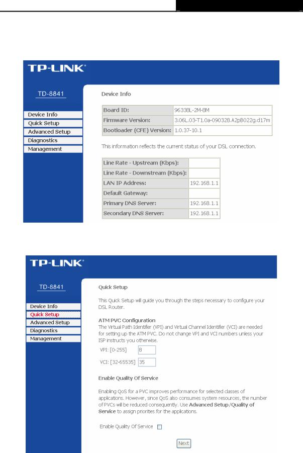
3.4Quick Setup
Figure 3-12 is the main page of the Router.
Figure 3-12
Please select Quick Setup. Enter the VPI and VCI values provided by your ISP and click Next.
Figure 3-13
Select the relevant Connection Type and Encapsulation Mode provided by your ISP and click
Next.
14
Loading...