


 Loading...
Toshiba Personal Computer
Satellite M200/M205
Satellite Pro M200
(PSMC0x)
(PSMC1x)
Maintenance Manual
TOSHIBA CORPORATION
S/ No
Satellite M200/M205 /Satellite Pro M200 Maintenance Manual

Copyright
© 2007 by Toshiba Corporation. All rights reserved. Under the copyright laws, this manual cannot be reproduced in any form without the prior written permission of Toshiba. No patent liability is assumed with respect to the use of the information contained herein.
Toshiba Satellite M200/M205 / Satellite Pro M200 Maintenance Manual
First edition May 2007
Disclaimer
The information presented in this manual has been reviewed and validated for accuracy. The included set of instructions and descriptions are accurate for the Satellite M200/M205 / Satellite Pro M200 at the time of this manual's production. However, succeeding computers and manuals are subject to change without notice. Therefore, Toshiba assumes no liability for damages incurred directly or indirectly from errors, omissions, or discrepancies between any succeeding product and this manual.
Trademarks
Intel and Pentium are registered trademarks of Intel Corporation.
IBM, IBM PC/XT, PC/AT, PS/2 and OS/2 are registered trademarks of IBM Corporation. Windows XP home edition are registered trademarks of Microsoft Corporation.
Sound Blaster and Pro are trademarks of Creative Technology Ltd. UNIX is a registered trademark of X/Open Company Ltd. NetWare are registered trademarks of Novell, Inc.
All other properties are trademarks or registered trademarks of their respective holders.
ii |
Satellite M200/M205 /Satellite Pro M200 Maintenance Manual |

Preface
This maintenance manual describes how to perform hardware service maintenance for the Toshiba Personal Computer Satellite M200/M205 / Satellite Pro M200, referred to as Satellite M200/M205 / Satellite Pro M200 in this manual.
The procedures described in this manual are intended to help service technicians isolate faulty Field Replaceable Units (FRUs) and replace them in the field.
SAFETY PRECAUTIONS
Four types of messages are used in this manual to bring important information to your attention. Each of these messages will be italicized and identified as shown below.
DANGER: “Danger” indicates the existence of a hazard that could result in death or serious bodily injury, if the safety instruction is not observed.
WARNING: “Warning” indicates the existence of a hazard that could result in bodily injury, if the safety instruction is not observed.
CAUTION: “Caution” indicates the existence of a hazard that could result in property damage, if the safety instruction is not observed.
NOTE: “Note” contains general information that relates to your safe maintenance service.
Improper repair of the computer may result in safety hazards. Toshiba requires service technicians and authorized dealers or service providers to ensure the following safety precautions are adhered to strictly.
Be sure to fasten screws securely with the right screwdriver. If a screw is not fully fastened, it could come loose, creating a danger of a short circuit, which could cause overheating, smoke or fire.
If you replace the battery pack, RTC battery or backup battery, be sure to use only the same model battery or an equivalent battery recommended by Toshiba. Installation of the wrong battery can cause the battery to explode.
Satellite M200/M205 /Satellite ProM200 Maintenance Manual |
iii |

The manual is divided into the following parts:
Chapter 1 Hardware Overview describes the Satellite M200/M205 / Satellite Pro M200 system unit and each FRU.
Chapter 2 Troubleshooting Procedures explains how to diagnose and resolve FRU problems.
Chapter 3 Test and Diagnostics describes how to perform test and diagnostic operations for maintenance service.
Chapter 4 Replacement Procedures describes the removal and replacement of the FRUs.
Appendices The appendices describe the following:
Handling the LCD Module
Board Layout
Pin Assignments
Keyboard scan/character codes
Key Layout
BIOS Rewrite Procedures
EC/KBC Rewrite Procedures
iv |
Satellite M200/M205 /Satellite Pro M200 Maintenance Manual |

Conventions
This manual uses the following formats to describe, identify, and highlight terms and operating procedures.
Acronyms
On the first appearance and whenever necessary for clarification acronyms are enclosed in parentheses following their definition. For example:
Read Only Memory (ROM)
Keys
Keys are used in the text to describe many operations. The key top symbol as it appears on the keyboard is printed in boldface type.
Key operation
Some operations require you to simultaneously use two or more keys. We identify such operations by the key top symbols separated by a plus (+) sign. For example, Ctrl + Pause (Break) means you must hold down Ctrl and at the same time press Pause (Break). If three keys are used, hold down the first two and at the same time press the third.
User input
Text that you are instructed to type in is shown in the boldface type below:
DISKCOPY A: B:
The display
Text generated by the XXXXX that appears on its display is presented in the type face below:
Format complete
System transferred
Satellite M200/M205 /Satellite ProM200 Maintenance Manual |
v |

Chapter 1
Hardware Overview

1 Hardware Overview
ii |
Satellite M200/M205/Satellite Pro M200 Maintenance Manual |

1 Hardware Overview
Chapter 1 |
Contents |
|
|
1.1 |
Features ......................................................................................................................... |
|
1 |
1.2 |
System Unit Components ............................................................................................. |
8 |
|
1.3 |
2.5-inch HDD.............................................................................................................. |
14 |
|
1.4 |
CD-RW/DVD-ROM Drive......................................................................................... |
15 |
|
1.5 |
DVD Super Multi (+-R Double Layer)....................................................................... |
17 |
|
1.6 |
Power Supply .............................................................................................................. |
18 |
|
1.7 |
Batteries ...................................................................................................................... |
|
19 |
|
1.1.1 |
Main Battery.......................................................................................... |
19 |
|
1.1.2 |
Battery Charging Control ...................................................................... |
19 |
|
1.1.3 |
RTC Battery .......................................................................................... |
20 |
Satellite M200/M205/Satellite Pro M200 Maintenance Manual |
iii |

1 Hardware Overview
Figures |
|
|
Figure 1-1 |
ID Parts Description Placement |
.........................................................................5 |
Figure 1-2 |
Computer Block Diagram.................................................................................. |
6 |
Figure 1-3 |
System Board Configurations............................................................................ |
7 |
Figure 1-4 |
System Unit Block Diagram.............................................................................. |
8 |
Figure 1-5 |
SATA HDD ..................................................................................................... |
14 |
Figure 1-6 |
CD-RW/DVD-ROM drive .............................................................................. |
15 |
Tables |
|
|
Table 1-1 |
HDD Specifications......................................................................................... |
14 |
Table 1-2 |
CD-RW/DVD-ROM Drive Specifications...................................................... |
15 |
Table 1-3 |
DVD Super Multi Drive (+-R Double Layer) Specifications ......................... |
17 |
Table 1-4 |
Battery Specifications...................................................................................... |
19 |
Table 1-5 |
Quick/Normal Charging Time......................................................................... |
20 |
iv |
Satellite M200/M205/Satellite Pro M200 Maintenance Manual |

1.1 Features |
1 Hardware Overview |
1.1Features
The Toshiba Satellite M200/M205/Satellite Pro M200 is a full size notebook PC based on the Core2 Duo Processor, Pentium Dual-Core Processor and Celeron M Processor, providing highspeed processing capabilities and advanced features. The computer employs a Lithium Ion battery that allows it to be battery-operated for a longer period of time. The display uses 14.1- inch WXGA LCD panel at a resolution of 1280 by 800 pixels. The uPGA socket supports BTO/CTO for the CPU so that the system can be designed to suit your needs.
The computer has the following features.
Processor
The CPU is the Core2 Duo Processor, Pentium Dual-Core Processor and Celeron M Processor.
Core2 Duo Processor (667MHz)
T5500(1.66G)/T5600(1.83G)/T7200(2.0G)/
T7400(2.16G)/T7600(2.33G) Hz
Core2 Duo Processor (533MHz)
T5200(1.66G)/T5300(1.73G)/
T2350(1.86G)/T2450(2.0G) Hz
Pentium Dual-Core Processor (533MHz)
T2060(1.60G)/T2080(1.73G) Hz
Celeron M Processor (533MHz)
520(1.60G)/530(1.73G) Hz (TDP: 30W)
Celeron M Processor (533MHz)
430(1.73G)/440(1.86G)/450(2.00G) Hz (TDP: 27W)
Host Bridge System Controller
System Controller: Intel 943GML/945GM + ICH7M
Satellite M200/M205/Satellite Pro M200 Maintenance Manual |
1 |
1 Hardware Overview |
1.1 Features |
Memory
The computer has two SO-DIMMs slot comes standard with DDRII-667MHz module. It supports PC2-5300 and uses SO-DIMMs (DDRII SDRAM) driven at 1.8 V, accepting BTO/CTO for your memory requirements. It can incorporate up to 4 GB of main memory.
Using the following sizes of memory modules:
y512 MB (32M×16×8P)/667 MHZ
y1024 MB (64M×8×16P)/667 MHZ
y2048 MB (64Mx16x16P)/667 MHZ
Hard Disk Drive (HDD)
The computer accommodates 9.5 mm height HDD with following storage capacities:
y80 GB (9.5 mm thick) SATA (5,400rpm)
y120 GB (9.5 mm thick) SATA (5,400rpm)
y160 GB (9.5 mm thick) SATA (5,400rpm)
y200 GB (9.5 mm thick) SATA (4,200rpm)
ODD
The computer accommodates a fixed 12.7 mm ODD with one of following 3 types:
yCD-RW/DVD ROM drive
yDVD Super Multi +-R Double Layer drive
yDVD Super Multi +-R Double Layer with Label Flash Support drive (BTO)
Display
The LCD display available comes in the type 14.1” WXGA HCSV color display, resolution 1280×800, 262,144 colors with dithering.
Keyboard
The keyboard has 30 kinds of country keyboards.
Battery
2 |
Satellite M200/M205/Satellite Pro M200 Maintenance Manual |

1.1 Features |
1 Hardware Overview |
The computer has a removable 3/6/9 Cell Lithium Ion battery pack and an internal RTC battery (rechargeable).
Universal Serial Bus (USB) Ports
The computer has four USB 2.0 ports. It is supported to daisy-chain a maximum of 127 USB devices. The serial data transfer rate is 480 Mbps or 12 Mbps and 1.5 Mbps. These ports support PnP installation and hot plugging.
External Monitor Port (BTO)
A 15-pin external monitor port is provided, through which the computer automatically recognizes an external VESA DDC 2B compatible monitor.
PC Card Slot (BTO)
A PC Card slot is provided to hold PC Card Standard Type II (5.0 mm) card, capable of using a variety of PC Cards including 16-bit Multiple Function PC Cards and 32-bit Card Bus Cards.
PC card HDD boot does not be supported.
SD/Mini SD/SD-IO/MS/MS Pro/MMC/XD Card Slot
This slot is for your memory card requirements to provide memory card read on your computer.
Toshiba Pointing Device
Toshiba Pointing Device has one kind of Synaptic Touchpad.
Sound System
The ALC268 integrated audio controller supports multimedia. The sound system contains the following:
yStereo speakers
yHeadphone jack
yInternal microphone
yExternal microphone jack
Satellite M200/M205/Satellite Pro M200 Maintenance Manual |
3 |

1 Hardware Overview |
1.1 Features |
LAN (BTO)
The internal LAN board supports 10/100Mbit or 10/100Mbit/1Gbit, enabling connection to a LAN at up to 1Gbps. It also supports Wake-up on LAN from S3/S4/S5 and PXE boot support. The LAN board has RJ45 jack to directly accommodate a LAN cable.
Wireless LAN
The internal Mini Card slot supports IEEE802.11g (MOW)/ IEEE802.11g (ROW) / IEEE802.11ag (MOW)/ IEEE802.11ag (ROW)/ IEEE802.11ag (JPN)/ IEEE802.11agn (MOW)/ IEEE802.11agn (ROW)/ IEEE802.11agn (JPN) card. The Antenna has three wires dual band antenna support for BTO.
Internal Modem (BTO)
The computer contains a MDC, enabling data and fax communication. It supports ITU- T V.90 (for rest countries)/V.92 (America, Canada, UK, Germany & France). The transfer rates are 56 Kbps for data reception, 33.6 Kbps for data transmission and 14,400 bps for fax transmission. Note, however, that the actual speed depends on the line quality. The RJ11 modem jack is used to accommodate a telephone line.
IEEE 1394
The IEEE 1394 serial data transfer rate is 400 Mbps, this port supports hot plugging.
Finger Print (BTO)
This product has a fingerprint utility installed for the purpose of enrolling and recognizing fingerprints. By enrolling the ID and password to the fingerprint authentication device, it is no longer necessary to input the password from the keyboard. Just by swiping the finger against the fingerprint sensor.
Internal Camera (BTO)
The computer has an internal camera. The camera has 1.3Mpix resolution support.
4 |
Satellite M200/M205/Satellite Pro M200 Maintenance Manual |

1.1 Features |
1 Hardware Overview |
Figures 1-1/1-2/1-3 and 1-4 show the computer and its system unit configuration, respectively.
Figure 1-1 ID Parts Description Placement
Satellite M200/M205/Satellite Pro M200 Maintenance Manual |
5 |

1 Hardware Overview |
1.1 Features |
||
|
|
|
|
|
|
|
|
Figure 1-2 Computer Block Diagram
6 |
Satellite M200/M205/Satellite Pro M200 Maintenance Manual |

1.1 Features |
1 Hardware Overview |
|
|
|
|
|
|
|
|
|
|
Figure 1-3 System Board Configurations
Satellite M200/M205/Satellite Pro M200 Maintenance Manual |
7 |

1 Hardware Overview |
1.2 |
|
System Unit Components |
1.2System Unit Components
Figure 1-4 is Block Diagram of the System Unit.
Figure 1-4 System Unit Block Diagram
8 |
Satellite M200/M205/Satellite Pro M200 Maintenance Manual |

1.2 System Unit Components |
1 Hardware Overview |
The system unit of the computer consists of the following components:
Processor: Core2 Duo Processor, Pentium Dual-Core Processor and Celeron M Processor.
yCore2 Duo Processor (667MHz)
−Core speed: 1.66/1.83/2.00/2.16/2.33 GHz
−System bus: 667 MHz
−On-die level 2 cache: 2 MB (1.66/1.83GHz)
−On-die level 2 cache: 4 MB (2.00/2.16/2.33GHz)
yCore2 Duo Processor (533MHz)
−Core speed: 1.66/1.73/1.86/2.00 GHz
−System bus: 533 MHz
−On-die level 2 cache: 2 MB
yPentium Dual-Core Processor (533MHz)
−Core speed: 1.60/1.73 GHz
−System bus: 533 MHz
−On-die level 2 cache: 1 MB
yCeleron M Processor (533MHz)
−Core speed: 1.60/1.73 GHz (TDP: 30W)
−System bus: 533 MHz
−On-die level 2 cache: 1 MB
yCeleron M Processor (533MHz)
−Core speed: 1.73/1.86/2.00 GHz (TDP: 27W)
−System bus: 533 MHz
−On-die level 2 cache: 1 MB
Memory: Two expansion memory slots are provided. They can hold 512/1024/2048MB expansion memory modules available as options to grow up to 4.0 GB.
yPC2-5300/667MHz DDRII SDRAM supported
y512/1024/2048MB modules supported
−512 MB (32M x 16 x 8P)
−1024 MB (64M x 8 x 16P)
−2048 MB (64M x 16 x 16P)
y1.8 volt operation
yNo parity bit
y64-bit data transfer
Satellite M200/M205/Satellite Pro M200 Maintenance Manual |
9 |

1 Hardware Overview |
1.2 |
|
System Unit Components |
BIOS ROM (Flash EEPROM)
y8Mb x 1 chip (1024KB flash parts)
−56Kb used for EC BIOS
−8Kb used for ESCD
−24Kb used for Memory Initial Code
−11.86Kb used for ACPI
−44.0Kb used for CPU update module
−64.0Kb used for Intel VGA BIOS
−55.29Kb used for Finger Printer ROM
−94.0Kb used for string data
−54.0Kb used for MARVELL 8039 LAN PXE ROM
−55.0Kb used for MARVELL 8055 LAN PXE ROM
−76.0Kb used for SMI
−54.0Kb used for PNP Code
−115.00Kb used for BIOS Code
−25.0Kb used for USB
−39.0Kb used for Setup
−9.31Kb used for AHCI
−5.0Kb used for Display Engine
−1.0Kb used for Decode Code
−2.0Kb used for Compress Code
−20.0Kb used for Pre-Shadow Code
−29.0Kb used for ROM Executable
−64Kb used for BOOTBLOCK
−863.6Kb used for Used Size
−160.4Kb used for Free Size
System Controllers
yNorth Bridge: Intel 943GML/945GM
−CPU Interface and Control
−System Memory Support
−PCI Express* Graphics (PEG) Interface
−Integrated Display Interface Support
−Internal Graphics Features
−Direct Media Interface (DMI)
−Power Management
−Serial ATA Interface
−ICH7 Audio Control
−SMBus 2.0/SMLink Interface
10 |
Satellite M200/M205/Satellite Pro M200 Maintenance Manual |

1.2 System Unit Components |
1 Hardware Overview |
ySouth Bridge: Intel ICH7-M
−Direct Media Interface (DMI)
−PCI Express* Interface
−Serial ATA (SATA) Controller
−Advanced Host Controller Interface (AHCI)
−PCI Interface
−IDE Interface
−Low Pin Count (LPC) Interface
−Compatibility Modules
−Advanced Programmable Interrupt Controller (APIC)
−Universal Serial Bus (USB) Controller
−LAN Controller
−Alert Standard Format (ASF) Management Controller
−RTC
−GPIO
−Enhanced Power Management
−Manageability
−System Management Bus (SMBus 2.0)
−Intel High Definition Audio Controller
−AC ’97 2.3 Controller
Graphics: Intel 943GML/945GM integrated graphics.
PC Card Controller: TI8412
yCardBus/PC Card Controller
y16-bit PCMCIA and 32-bit CardBus
ySD/SD-IO/MS/MS Pro/MMC/XD Card Controller
Audio Controller: Realtek ALC268 integrated audio controller supports multimedia. The sound system feature contains the following:
y2 Stereo DACs support 16/20/24-bit PCM format for stereo audio playback.
y2 stereo ADCs support 16/20-bit PCM format for two stereo independent sound inputs.
y16/20/24-bit S/PDIF-OUT supports 44.1/48/88.2/96/192 KHz sample rate.
yAll ADCs support 44.1/48/96 KHz sample rate.
y4 GPIOs (GPIO0 / GPIO3 are digital GPIO shared with digital MIC interface, GPIO1 / GPIO2 are analog) for customized applications.
yHigh quality analog differential CD input.
Satellite M200/M205/Satellite Pro M200 Maintenance Manual |
11 |
1 Hardware Overview |
1.2 |
|
System Unit Components |
y2 jack detection pins each designed to detect up to 4 jacks.
ySupports hardware digital volume control for digital microphone input.
ySupport external PCBEEP input and built-in digital BEEP generator.
KBC/EC (Keyboard Controller/Embedded Controller): A single KBC W8763 chip is used to serve as KBC/EC and Super IO.
yKBC
−Scan controller function
−Interface controller function
yEC
−Power supply sequence control
−Overheat shutdown support
−LED control
−Beep control
−Device ON/OFF
−Cooling fan speed control
−Universal I/O port
−Battery capacity check
−Flash memory reprogramming function
−EC access interface
−I2C communication control
Battery EEPROM
y24C02 equivalent (128 words x 16 bits, I2C interface) integrated in battery pack.
−Store records of battery use
Clock Generator
yICS9LPRS316
−Generate the clock signal required for the system
Modem Controller: Built-in MDC card with Askey / Foxconn.
yDigital signal conductor protection
yRing wake-up support
yAzalia interface
12 |
Satellite M200/M205/Satellite Pro M200 Maintenance Manual |

1.2 System Unit Components |
1 Hardware Overview |
yCommunication codes supported:
−For data communication:
V.90 (China)/V.92, data rates: 28kbps/56kbps
V.34 extended rates: 33.6K/2400/V.32 turbo, V.32 bits and fallbacks − For fax:
V.17, V.27, V.29, V.34 and V.21 Channel 2 V.253 Class 1 fax
LAN Controller: MARVELL8039 10/100Mbit or MARVELL8055 10/100Mbit/1Gbit.
yIEEE 802.3 10BASE-T/100BASE-TX compliant physical layer interface
yIEEE 802.3u Auto-Negotiation support
yDigital adaptive equalization control
y10BASE-T auto-polarity correction
yLAN Connect interface
yAutomatic detection of “unplugged mode”
yRemote boot (PXE 2.1)
ySmart power down when link is not detected
Wireless LAN Controller
ySupport following 3 kinds of mini PCI wireless LAN cards
−IEEE 802.11g
−IEEE 802.11ag
−IEEE 802.11agn
yData Rate
−IEEE 802.11g: Standard 54M bps
−IEEE 802.11ag: Standard 54M bps
−IEEE 802.11agn: Standard 130M bps
yFrequency Channel
−IEEE802.11g: 2.4GHz
−IEEE802.11ag: 2.4GHz / 5.4GHz
−IEEE802.11agn: 2.4GHz / 5.4GHz
Satellite M200/M205/Satellite Pro M200 Maintenance Manual |
13 |

1 Hardware Overview |
1.3 2.5-inch HDD |
1.32.5-inch HDD
The computer contains an extremely low-profile and lightweight, high-performance HDD. The HDD incorporates 9.5 mm height magnetic disk and mini-Winchester type magnetic heads. The HDD interface conforms to Serial ATA. Storage capacities supported are 80, 120, 160, 200 GB.
The HDD is shown in Figure 1-5 and some of its specifications are listed in Table 1-1.
Figure 1-5 SATA HDD
Table 1-1 HDD Specifications
Item |
|
Specifications |
|
|
|
|
|
Capacity (GB) |
80 GB |
|
120 GB |
|
|
|
|
Rotational Speed (RPM) |
5400 rpm |
|
5400 rpm |
|
|
|
|
Height |
9.5 mm |
|
9.5 mm |
|
|
|
|
User Data Sectors |
156,301,488 |
|
234,442,648 |
|
|
|
|
Bytes / Sector |
512 |
|
512 |
|
|
|
|
Item |
|
Specifications |
|
|
|
|
|
Capacity (GB) |
160 GB |
|
200 GB |
|
|
|
|
Rotational Speed (RPM) |
5400 rpm |
|
4200 rpm |
|
|
|
|
Height |
9.5 mm |
|
9.5 mm |
|
|
|
|
User Data Sectors |
312,581,808 |
|
390,721,968 |
|
|
|
|
Bytes / Sector |
512 |
|
512 |
|
|
|
|
14 |
Satellite M200/M205/Satellite Pro M200 Maintenance Manual |
1.4 |
CD-RW/DVD-ROM Drive |
|
1 Hardware Overview |
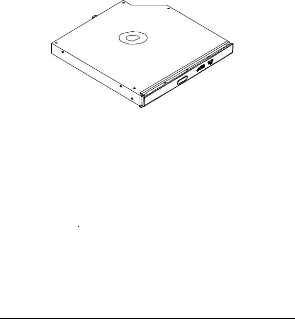
1.4CD-RW/DVD-ROM Drive
The CD-RW/DVD-ROM drive accepts 12-cm (4.72-inch) and 8-cm (3.15-inch) discs. At maximum, the drive can play back a DVD at 8x speed, read CD-ROM at 24x speed, and write CD-R at 24x speed, HS CD-RW at 10x speed, US CD-RW at 24x speed and CD-RW at 4x speed.
The CD-RW/DVD-ROM drive is shown in Figure 1-6 and its specifications are listed in Table 1-2.
Figure 1-6 CD-RW/DVD-ROM drive
Table 1-2 CD-RW/DVD-ROM Drive Specifications
Item |
DVD-ROM mode |
|
CD-RW mode |
Data Transfer Rate |
33.3 (U-DMA transfer mode 2) |
|
|
(Mbytes/s) |
16.7 (PIO mode 4, Multiword DMA mode 2) |
|
|
|
|
||
Access Time (ms) |
|
|
|
Average Random |
150 ms |
|
130 ms |
Access |
|
||
|
|
|
|
Data Buffer Size |
2MB |
|
|
(Mbytes) |
|
||
|
|
|
|
Formats Supported |
DVD: |
|
|
|
DVD-ROM, DVD-R, DVD-RAM. |
|
|
|
CD: |
|
|
Satellite M200/M205/Satellite Pro M200 Maintenance Manual |
15 |

1 Hardware Overview |
1.5 |
|
DVD Super Multi (+-R Double Layer) |
CD-DA,CD+(E)G,CD-MIDI,CD-TEXT,CD-ROM,CD-ROM XA,MIXED
MODE CD,CD-I,CD-I Bridge(Photo CD, Video CD), Multi-Session
CD(Photo CD, CD-EXTRA, Portfolio, CD-R,CD-RW),CD-R,CD-RW.
16 |
Satellite M200/M205/Satellite Pro M200 Maintenance Manual |

1.4 |
CD-RW/DVD-ROM Drive |
|
1 Hardware Overview |
1.5DVD Super Multi (+-R Double Layer)
The DVD Super Multi drive accepts 12-cm (4.72-inch) and 8-cm (3.15-inch) discs. At maximum, the drive can play back a DVD at 8x speed, read CD-ROM at 24x speed, and write CD-R at 24x speed, CD-RW at 4x speed, US CD-RW at 24x speed, High Speed CDRW at 10x speed, DVD-R at 8x speed, DVD-RW at 6x speed, DVD+R at 8x speed, DVD+R (Double Layer) at 4x speed, DVD-R (Double Layer) at 4x speed, DVD+RW at 8x speed and DVD-RAM at 5x speed.
The specifications of the DVD Super Multi (+-R Double Layer) drive are listed in Table 1-3.
Table 1-3 DVD Super Multi Drive (+-R Double Layer) Specifications
Item |
DVD-ROM Mode |
|
CD-ROM Mode |
|
|
|
|
Data Transfer Rate |
33.3 (U-DMA transfer mode 2) |
|
|
(Mbytes/s) |
|
||
16.6 (PIO mode 4, Multiword DMA mode 2) |
|
||
|
|
||
|
|
|
|
Access Time (ms) |
|
|
|
Average Random |
130 |
|
130 |
Access |
|
||
|
|
|
|
Data Buffer Size |
2MB |
|
|
(Mbytes) |
|
||
|
|
|
|
|
DVD: |
|
|
|
DVD-VIDEO, DVD-ROM, DVD-R, DVD-RW, DVD-RAM, |
||
Formats Supported |
DVD+R, DVD+-R (Double Layer), DVD+RW. |
|
|
|
|
|
|
|
CD: |
|
|
|
CD-DA, CD-ROM, CD-R, CD-RW, CD-ROMXA, Photo CD (Multi- |
||
|
Session), Video CD, CD-Extra (CD+), CD-Text. |
||
|
|
|
|
Satellite M200/M205/Satellite Pro M200 Maintenance Manual |
17 |

1 Hardware Overview |
1.7 |
|
Batteries |
1.6Power Supply
The power supply unit provides many different voltages for the system board and performs the following functions:
1. Power input monitor
yChecks whether the DC power supply (AC adapter) is connected to the computer.
yChecks whether the battery pack is connected to the computer.
yMonitors the DC power supply input voltage (AC Adapter output voltage).
2.Power supply's internal control
yTurns on and off the battery pack charging power supply.
yIssues a charging current instruction to the PWM control IC of the battery pack charging power supply.
yControls the supply of DC power supply input (AC Adapter output) to the power supply unit.
yControls the supply of power to the system block (load/logic circuit side).
yControls forced shutdown if the power supply malfunctions.
3.Logic circuit control
yInstructs the gate array to enable/disable tuning the power on.
yControls power-on/off operation.
4.Status display
yTurns on the Power LED (in Blue or AMBER).
yBattery indicator (in Blue or AMBER or AMBER Flash).
5.External interface
yPerforms communication through the I2C bus (via the internal EC/KBC).
yTransfers the power supply operation mode.
6.Output monitor
yMonitors the voltage output to the system block (load/logic circuit side).
yMonitors the voltage, over voltage, input/output current of the battery pack.
yMonitors the internal temperature of the battery pack.
yMonitors the supply voltage from the AC adapter.
18 |
Satellite M200/M205/Satellite Pro M200 Maintenance Manual |

1.6 |
Power Supply |
|
1 Hardware Overview |
1.7Batteries
The computer has the following four types of batteries:
Main Battery Pack
Real Time Clock (RTC) Battery
Table 1-4 lists the specifications of these batteries.
Table 1-4 Battery Specifications
Battery Type |
|
Material |
Output voltage |
Capacity |
|
|
|
|
|
|
3 Cell |
Lithium Ion |
10.8 V |
2000 mAh |
Main Battery Pack |
|
|
|
|
6 Cell |
Lithium Ion |
10.8 V |
4000 mAh |
|
|
|
|
|
|
|
9 Cell |
Lithium Ion |
10.8 V |
6000 mAh |
|
|
|
|
|
RTC Battery |
|
Lithium Ion |
3.0 V |
14 mAh |
|
|
|
|
|
1.1.1Main Battery
The main battery pack serves as the computer's main power source when the AC adapter is not attached. The main battery maintains the state of the computer so that it can resume it.
1.1.2Battery Charging Control
Battery charging is controlled by WINBOND 8763L. When the AC adapter and battery pack are attached to the computer, the 8763L controls the charge on/off state and detects a full charge.
Battery Charge
Satellite M200/M205/Satellite Pro M200 Maintenance Manual |
19 |

1 Hardware Overview |
1.7 |
|
Batteries |
When the AC adapter is attached, the battery is charged by off-state charge when the system is powered off or by on-state charge when it is powered on.
Table 1-5 Quick/Normal Charging Time
State |
|
Charge Time |
|
|
|
|
|
Off-State Charge |
3/6/9 Cell |
|
About 4 hours max |
|
|
|
|
On-State Charge |
3/6/9 Cell |
|
About 4~10 hours max |
|
|
|
|
NOTE: The time required for normal charge depends on the power consumption by the system. Using the fluorescent lamp and frequently accessing the disk consume much power and lengthen the charge time.
Any of the following cases stops battery charge:
1.The battery becomes fully charged.
2.The AC adapter or battery pack is removed.
3.The battery or AC adapter voltage is abnormal.
Detection of full charge
A full charge is detected only when the battery is being charged by quick or normal charge. A full charge is detected when either of the following conditions is met:
1.The current in the battery charging circuit drops below the predetermined value.
2.The charging time exceeds the fixed limit.
1.1.3RTC Battery
The RTC battery provides power to keep the current date, time and other system information in memory while the computer is turned off.
20 |
Satellite M200/M205/Satellite Pro M200 Maintenance Manual |

2 Troubleshooting
Chapter 2
Troubleshooting
2-i |
Satellite M200/M205 /Satellite Pro M200 Maintenance Manual |
Loading...