


FILE NO. SVM-09028
SERVICE MANUAL
AIR CONDITIONER
SPLIT WALL TYPE
RAS-13SKP-ES / RAS-13SA-ES RAS-13SKP-ES(HK) / RAS-13SA-ES
April, 2009
FILE NO. SVM-09028
CONTENTS
1.SPECIFICATIONS
2.CONSTRUCTION VIEWS
2-1 Indoor Unit
2-2 Outdoor Unit
3.WIRING DIAGRAM
4.SPECIFICATION OF ELECTRICAL PARTS
4-1 Indoor Unit
4-2 Outdoor Unit
5.REFRIGERATION CYCLE DIAGRAM
6.CONTROL BLOCK DIAGRAM
7.OPERATION DESCRIPTION
7-1 Remote control
7-2 Outline of Air Conditioner Control
7-3 Description of Operation Mode
7-4 Low-Temperature Limit Control
7-5 One-Touch Operation
7-6 Hi POWER Operation
7-7 QUIET Operation
7-8 ECO Operation
7-9 COMFORT SLEEP Operation
7-10 FILTER Check lamp
7-11 Auto Restart Function
7-12 Self-Cleaning Operation
8.INSTALLATION PROCEDURE
8-1 Safety Cautions
8-2 Installation Diagram of Indoor and Outdoor Units 8-3 Installation
8-4 Indoor Unit
8-5 Outdoor Unit
8-6 How to Set Remote Control Selector Switch 8-7 Others
− 1 −
FILE NO. SVM-09028
9.TROUBLESHOOTING CHART
9-1 Troubleshooting Procedure
9-2 Basic Check Items
9-3 Primary Judgement
9-4 Self-Diagnosis by Remote Control (Check Code) 9-5 Troubleshooting Flowcharts
9-6 Troubleshooting for Remote Control (Including The Indoor P.C. Board)
10.PARTS REPLACE MAIN PARTS
10-1 Indoor Unit
10-2 Outdoor Unit
11.EXPLODED VIEWS AND PARTS LIST
11-1 Indoor Unit (E-Parts Assy)
11-2 Indoor Unit
11-3 Outdoor Unit
– − 2 −–

FILE NO. SVM-09028
1. SPECIFICATIONS
|
MODEL |
|
RAS-13SKP-ES / RAS-13SA-ES |
||
|
|
RAS-13SKP-ES(HK) / RAS-13SA-ES |
|||
|
|
|
|
||
ITEM |
|
|
|
Cooling |
|
Capacity |
|
|
220V |
240V |
|
|
kW |
3.75 |
3.75 |
||
|
|
||||
|
Phase |
|
1 |
||
Power source |
|
V |
|
220 − 240 |
|
|
|
Hz |
|
50 |
|
Power consumption |
kW |
1.13 |
1.17 |
||
Power factor |
|
% |
95 |
91 |
|
Running |
Indoor |
A |
|
0.15 |
|
current |
Outdoor |
A |
5.40 |
5.35 |
|
Starting current |
A |
|
29 |
||
Moisture removal |
lit/h |
|
2.0 |
||
Noise |
Indoor (H/M+/M/L+/L) dB |
|
41/38/35/33/31 |
||
Outdoor (220-240V) |
dB |
50 |
51 |
||
|
|||||
Refrigerant |
Name of refrigerant |
|
|
R410A |
|
Rated amount |
kg |
|
0.98 |
||
|
|
||||
Refrigerant control |
|
|
Capillary tube |
||
|
Gas side size |
mm |
|
12.7 |
|
|
Connection type |
|
|
Flare connection |
|
|
Liquid side size |
mm |
|
6.35 |
|
Interconnection |
Connection type |
|
|
Flare connection |
|
pipe |
Maximum length |
m |
|
15*1 |
|
|
(One way) |
|
|
|
|
|
Maximum height |
m |
|
6 |
|
|
difference |
|
|||
|
|
|
|
||
INDOOR UNIT |
|
|
|
RAS-13SKP-ES, RAS-13SKP-ES(HK) |
|
|
Height |
mm |
|
275 |
|
Dimensions |
Width |
mm |
|
790 |
|
|
Depth |
mm |
|
205 |
|
Net weight |
|
kg |
|
9 |
|
Evaporator type |
|
|
Finned tube |
||
Indoor fan type |
|
|
|
Cross flow fan |
|
|
High fan |
m3/h |
|
600 |
|
Airflow volume Medium fan |
m3/h |
|
470 |
||
|
Low fan |
m3/h |
|
360 |
|
Fan motor output |
W |
|
20 |
||
Air filter |
|
|
|
Honeycomb woven filter with PP frame |
|
OUTDOOR UNIT |
|
|
RAS-13SA-ES |
||
|
Height |
mm |
|
550 |
|
Dimensions |
Width |
mm |
|
780 |
|
|
Depth |
mm |
|
290 |
|
Net weight |
|
kg |
|
36 |
|
Condenser type |
|
|
Finned tube |
||
Outdoor fan type |
|
|
Propeller fan |
||
Airflow volume |
|
m3/h |
2120 |
2200 |
|
Fan motor output |
W |
|
42 |
||
Compressor |
Model |
|
|
PA150X2C-4FT |
|
Output |
W |
|
1100 |
||
|
|
||||
Safety device |
|
|
|
Fuse, Overload relay |
|
Louver type |
|
|
|
Automatic louver |
|
Usable outdoor temperature range |
°C |
|
21 ~ 43 |
||
|
|
|
− 3 − |
|
|
FILE NO. SVM-09028
Note : 1
∙ Capacity is based on the following temperature conditions.
|
Condition |
JIS C9612 |
|
Temperature |
Cooling |
||
|
|||
Indoor unit inlet air temperature |
(DB) |
27 °C |
|
(WB) |
19 °C |
||
|
|||
Outdoor unit inlet air temperature |
(DB) |
35 °C |
|
(WB) |
24 °C |
||
|
|||
Note : 2 |
|
|
*1 No need to charge extra refrigerant.
− 4 −

FILE NO. SVM-09028
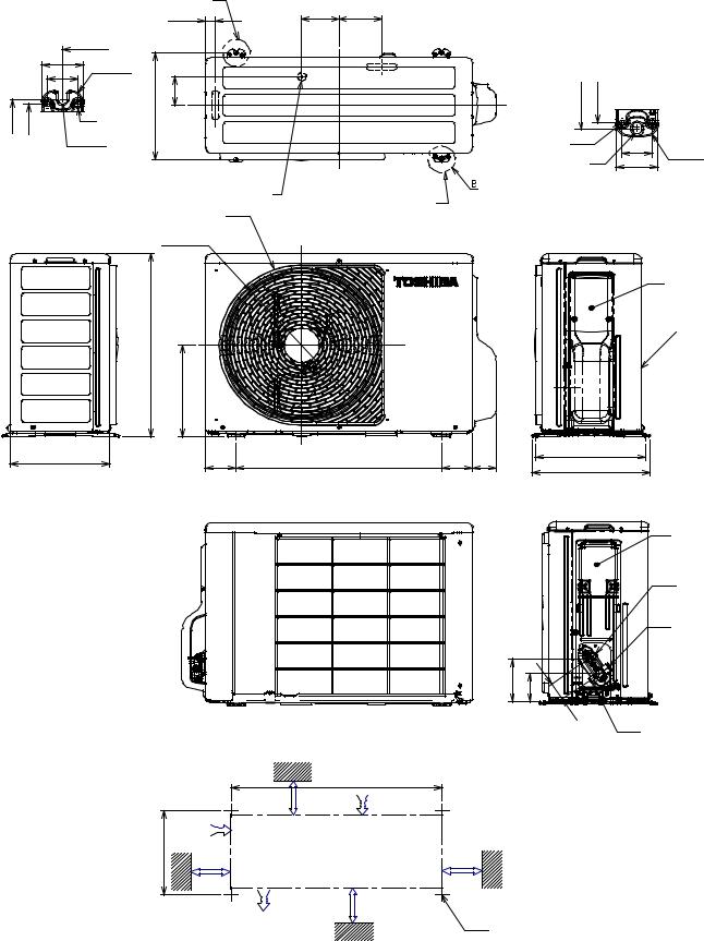
2. CONSTRUCTION VIEWS
2-1. Indoor Unit
790
Front panel
63
7
Air filter |
Air inlet |
|
|
|
|
|
|
|
|
|
|
|
275 |
48 |
Heat exchanger |
205
63
48 |
7 |
Knock out system |
Knock out system |
49
62 69
116 |
480 |
193 |
|
Installation plate hanger |
|
|
157 |
56 |
19 |
Wireless remote controller
Installation plate hanger |
Drain hose (0.50m) |
Connecting pipe (0.35m) |
Connecting pipe (0.40m) |
(Flare 12.7mm) |
(Flare 6.35mm) |
|
84.5 |
|
235 |
621 |
|
84.5 |
|
|
|
|
235 |
|
|
|
|
|
|
|
215 |
215 |
|
|
|
|
|
|
|
Minimum |
more |
|
|
|
|
|
Hanger |
distance |
|
|
|
|
|
|
65 or |
|
|
||
|
|
|
to ceiling |
|
|
||
|
|
|
|
|
|
||
|
Minimum |
|
|
|
|
|
45 |
|
|
|
|
|
Minimum |
|
|
|
distance |
|
|
|
|
|
|
|
|
|
|
|
distance |
|
|
|
to wall |
|
|
|
|
|
|
275 |
|
|
|
|
to wall |
190 |
|
|
|
|
|
|
|||
170 or more |
|
|
|
|
170 or more |
||
|
|
|
|
|
|
||
|
40 |
|
|
|
|
|
40 |
|
|
Hanger |
|
|
Hanger |
|
|
|
84.5 |
150 |
160.5 |
160.5 |
150 |
84.5 |
|
|
|
|
Center line |
|
Installation plate outline |
|
|
|
|
|
– 5 – |
|
|
|
|
|
125 |
63 |
26 |
Remote controller holder
|
|
|
|
|
|
|
FILE NO. SVM-09028 |
|||
|
2-2. Outdoor Unit |
|
|
|
|
|
|
|||
|
|
|
|
A |
|
|
|
|
|
|
|
|
|
|
28 |
108 |
125 |
|
|
|
|
|
|
|
600 |
|
|
|
|
|
|
|
|
|
50 |
R15 |
|
|
|
|
|
|
|
|
|
36 |
|
|
|
|
|
|
|
|
|
|
|
|
|
|
|
|
|
|
|
|
|
|
320 |
86 |
|
|
320 |
306 |
|
|
320 |
306 |
|
Ø6 hole |
|
|
|
|
|
|
|
|
R5.5 |
|
|
|
|
|
|
|
||
|
|
|
|
|
|
Ø6 hole |
|
36 |
|
|
|
|
|
|
|
|
|
|
R15 |
||
|
|
|
|
|
|
|
|
|
||
|
|
|
|
|
|
|
Ø11x14 hole |
50 |
||
|
|
|
|
|
|
|
|
|||
A detail Drawing (Back leg) |
|
2- Ø11 x 14 Hole |
|
|
|
|
||||
|
|
|
|
Ø25 Drain outlet |
B Detail Drawing (Front leg) |
|||||
|
|
|
|
|
(For Ø8 -Ø10 anchor bolt) |
|
|
|
|
|
550 |
290 |
FAN-GUARD |
|
|
|
Ø 436 |
|
|
|
275 |
|
|
|
90 |
600 |
90 |
69 |
320 |
342 |
COVER-PV
Z
|
|
Electrical part cover |
|
|
Liquid side |
|
|
(Flare Ø6.35) |
|
|
Gas side |
|
|
(Flare Ø12.7) |
129 |
84 |
5 |
4 |
|
Z View |
Service port |
|
600 |
|
100 or more |
|
Air intlel |
|
|
600 or more |
320 |
|
|
100 or more |
Air outlel |
600 or more |
|
|
|
|
|
4x Ø11 Long holes(For Ø8Ø10 anchor bolt) |
− 6 −
FILE NO. SVM-09028
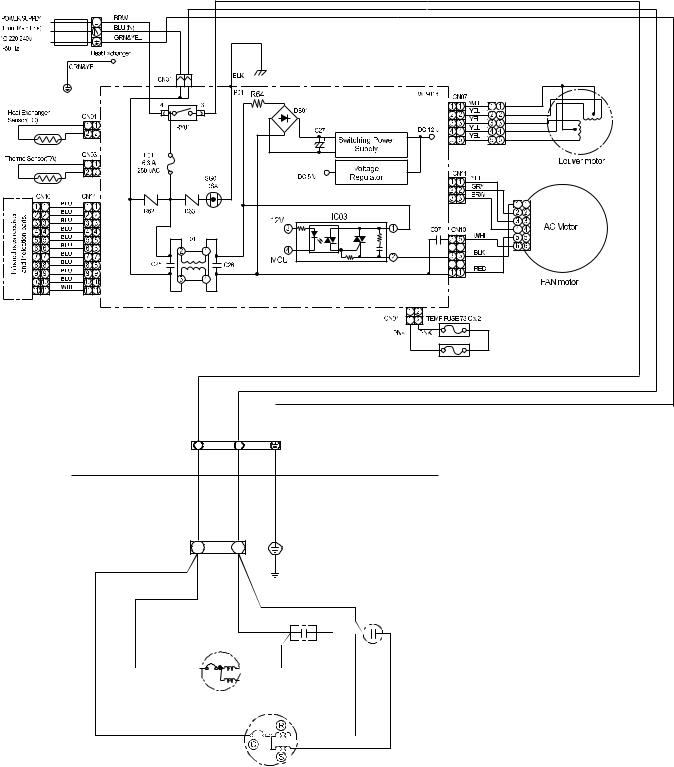
3. WIRING DIAGRAM
INDOOR TERMINAL BLOCK
BLK
1
WHI
2
GRN&YEL
INDOOR
OUTDOOR
|
OUTDOOR |
|
|
|
|
|
TERMINAL |
|
|
|
|
|
BLOCK |
1(L) |
2(N) |
CHASSIS |
|
|
|
|
|
RED |
|
BLK |
BLK |
|
RED |
CAPACITOR |
CAPACITOR |
|
|
|
|
FAN MOTOR
RED
WHI
COMPRESSOR
PNK
WHI
− 7 −
FILE NO. SVM-09028
4. SPECIFICATION OF ELECTRICAL PARTS
4-1. Indoor Unit
No. |
Parts name |
Type |
Specifications |
1 |
Fan motor (for indoor) |
AFN- 220-20-4D |
° |
AC Motor with 145 C thermo fuse |
|||
2 |
Thermo sensor (TA-sensor) |
|
10kW at 25°C |
|
|
|
|
3 |
Transformer |
ST-02 |
|
4 |
Microcontroller unit (IC30) |
TMP87CM40ANG |
|
|
|
|
|
5 |
Heat exchanger sensor |
|
10k Wat 25°C |
|
(TC-sensor) |
|
|
|
|
|
|
|
|
|
|
6 |
Line filter (L01) |
SS11V-R06270 |
27mH, 600mA |
|
|
|
|
7 |
Bridge rectifier (DB01) |
DB105G |
1.0A, 600 V |
|
|
|
|
8 |
Capacitor (C27) |
EKMH401VSN470MP205S |
47mF, 400 V |
|
|
|
|
9 |
Fuse (F01) |
FJL250V6.3A |
6.3A, 250VAC |
|
|
|
|
10 |
Varistor (R62, R63) |
SR561K14DL |
560 V |
|
|
|
|
11 |
Louver motor |
MP24Z3T |
12VDC |
|
|
|
|
12 |
Relay (Comp., RY01) |
891WP-1A-C |
Rating 25A/AC250V |
|
|
|
|
4-2. Outdoor Unit
No. |
Parts name |
Type |
Specifications |
|
||
|
|
|
Output (Rated) 1100W, 2poles, 1 phase, 220 − 240V, 50Hz |
|||
|
|
PA150X2C-4FT |
|
|
|
|
1 |
Compressor |
Winding resistance (Ω ) |
C-R |
C-S |
||
|
|
|
(at 20°C) |
|
|
|
|
|
|
2.35 |
3.22 |
||
|
|
|
|
|
|
|
|
Fan motor |
WLF-240-42A |
Output (Rated) 30W, 6poles, 1 phase, 220 − 240V, 50Hz |
|||
|
|
|
|
|||
2 |
Winding resistance (Ω ) |
Red-Black |
White-Black |
|||
(for outdoor) |
|
|||||
|
|
(at 20°C) |
|
|
||
|
|
188 |
289 |
|||
|
|
|
||||
|
|
|
|
|
|
|
3 |
Running capacitor |
DS451155NPQB |
AC 450V, 1.5μF |
|
|
|
(for fan motor) |
|
|
||||
|
|
|
|
|
||
|
|
|
|
|
|
|
4 |
Running capacitor |
B32332I5306J063 |
AC 450V, 30μF |
|
|
|
(for compressor) |
|
|
||||
|
|
|
|
|
||
|
|
|
|
|
|
|
− 8 −
FILE NO. SVM-09028
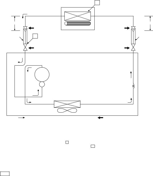
5. REFRIGERATION CYCLE DIAGRAM
|
|
Indoor unit |
T1 |
|
|
|
|
|
Cooling |
Heat exchanger |
|
|
|
|
|
0.39 m |
|
|
0.49 m |
(Connecting pipe) |
|
(Connecting pipe) |
|
Æ12.7 |
|
Cross flow fan |
Æ6.35 |
|
|
|
|
O.D.:9.52 mm |
P |
|
O.D.:6.35 mm |
|
Packed valve |
|
Packed valve |
|
(Æ12.7) |
|
(Æ6.35) |
Cooling |
Cooling Compressor |
PA150X2C-4FT
Heat exchanger
Capillary tube Æ1.7 x 700l
|
|
|
Refrigerant |
|
Propeller fan |
|
R22 : 0.98 kg. |
Cooling |
Outdoor unit |
Mark ( |
) means check points of Gas Leak. |
|
|
Standard |
Surface temp. of heat |
|
Ambient temp. |
||
|
|
Fan speed |
conditions DB/WB |
||||
|
50Hz |
pressure P |
exchanger interchanging |
(indoor) |
|
(° C) |
|
|
|
(MPaG) |
pipe T1 (° C) |
|
|
|
|
|
|
|
Indoor |
|
Outdoor |
||
|
|
|
|
|
|
||
|
|
|
|
|
|
|
|
|
Standard |
1.03 |
10.0 |
High |
27/19 |
|
35/24 |
|
|
|
|
|
|
|
|
Cooling |
Overload |
1.14 |
14.5 |
High |
32/23 |
|
43/26 |
|
|
|
|
|
|
|
|
|
Low temperature |
0.53 |
2.0 |
Low |
21/15 |
|
21/15 |
|
|
|
|
|
|
|
|
Note
∙ Measure the heat exchanger temperature at the center of U-bend. (By means of TC sensor)
− 9 −
FILE NO. SVM-09028
6. CONTROL BLOCK DIAGRAM
Main Unit Control Panel |
M.C.U. |
Heat Exchange sensor
Thermo. Sensor
Infrared Rays Signal Reciver
Initiallizing Circuit
Clock Frequency
Oscillator Circuit
Power Supply
Circuit
Noise Filter
 Functions
 ∙ Louver Control
 ∙ 3-minutes Delay at Restart
for Compressor

 ∙ Motor Revolution Control
 ∙ Processing
(Temperature Processing)  ∙ Timer
Compressor
ON/OFF
Signal
Operation
Display
Timer
Display
Filter Sign
Display
Hi Power
 Sign Display
Fan Only
 Sign Display
Indoor Fan
Motor
Louver
ON/OFF
Signal
|
|
|
Louver |
|
Relay Driver, Louver Driver |
||
|
|
Motor |
|
|
|
|
|
|
|
|
|
|
|
|
|
Relay
RY01
220-240 V~, 50Hz |
Compressor, Outdoor Fan Motor |
|
REMOTE CONTROL |
Infrared Rays |
|
Remote Control |
||
|
Operation ( )
)
Operation Mode Selection
AUTO, COOL, DRY, FAN ONLY
Temperature Setting
Fan Speed Selection
ON TIMER Setting
OFF TIMER Setting
Louver Auto Swing
Louver Direction Setting
ECO
Hi power
TIMER 1.3.5.9H
COMFORT SLEEP
QUIET
− 10 −
FILE NO. SVM-09028
7. OPERATION DESCRIPTION
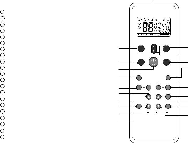
7-1. Remote control |
1 |
7-1-1. Function of Push Putton
1Infrared signal emitter
2Start/Stop button
3Mode select button (MODE)
4Temperature button (TEMP)
5Fan speed button (FAN)
6Swing louver button (SWING)
7Set louver button (FIX)
8On timer button (ON)
9Off timer button (OFF)
Sleep timer button (SLEEP)
Timer setup button (SET)
Timer clear button (CLR)
13Memory and Preset button (PRESET)
14One Touch button (ONE-TOUCH)
15High power button (Hi-POWER)
16Economy button (ECO)
17Quiet button (QUIET)
18Comfort sleep button (COMFORT SLEEP)
19Filter reset button (FILTER)
20Clock Reset button (CLOCK)
21Check button (CHK)
TOSHIBA
13 |
PRESET |
|
FAN |
5 |
|
|
TEMP |
||
|
|
|
|
|
|
ONE-TOUCH |
|
MODE |
4 |
|
|
|
||
14 |
|
|
|
3 |
2 |
|
|
COMFORT |
18 |
|
QUIET |
|
SLEEP |
|
17 |
|
|
|
15 |
|
SWING |
FIX |
Hi-POWER ECO |
|
|
|
|||
6 |
|
|
|
16 |
7 |
TIMER |
|
CLR |
12 |
8 |
|
|||
|
ON |
OFF |
9 |
|
|
|
|||
10 |
SLEEP |
|
SET |
11 |
21 |
|
|
|
|
CHK |
|
FILTER CLOCK |
20 |
|
|
|
|||
|
|
|
|
|
19 |
|
|
|
|
− 11 −
FILE NO. SVM-09028
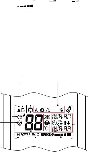
7-1-2. Display of Remote Control
All indications, except for the clock time indicator, are displayed by pressing the  button.
1.Transmission mark
This transmission mark  indicates when the remote controller transmits signals to the indoor unit.
2. Mode indicator
Indicates the current operation mode.
(A : Auto,  : Cool,
  : Dry,
  : Fan only)
3. Temperature indicator
Indicates the temperature setting. (17°C to 30°C)
4. FAN speed indicator
Indicates the selected fan speed.
AUTO or five fan speed levels
(LOW  , LOW+
  , MED
, MED  , MED+
  ,
,
HIGH |
) can be shown. |
Indicates AUTO when the operating mode is either AUTO or  : Dry.
5. TIMER and clock time indicator
The time setting for timer operation or the clock time is indicated.
The current time is always indicated except during TIMER operation.
6. Hi-POWER indicator
Indicates when the Hi-POWER operation starts.
Press the Hi-POWER button to start and press it again to stop the operation.
7.  (PRESET) indicator
Flashes for 3 seconds when the PRESET button is pressed during operation.
The  mark is shown when holding down the button for more than 3 seconds while the mark is blinks.
Press another button to turn off the mark.
8. ECO indicator
Indicates when the ECO is in activated.
Press the ECO button to start and press it again to stop operation.
9. A, B change indicator remote controller
9 |
|
|
|
1 |
12 |
2 |
13 |
|
|
10
11
|
|
|
|
|
|
|
|
|
|
|
|
|
|
|
|
|
|
|
|
|
|
|
|
|
|
|
|
|
|
|
|
|
|
|
|
|
|
8 |
|
|
|
|
5 |
|
6 |
|
4 |
||||||
|
|
|
|
|||||
|
|
|
||||||
3 |
|
7 |
|
|
|
|||
|
|
|
|
|
|
|
||
When the remote controller switching function is set, “B” appears in the remote controller display. (When the remote controller setting is “A”, there is no indication at this position.)
10. Comfort sleep
Indicates when comfort sleep is activaled. Press comfort sleep button to selectter
11. Quiet
Indicates when quiet is activated.
Press quiet button to start and press it again to stop operation.
12. One-Touch
Indicates when one touch comfort is activated. Press one-touch button to start the operation.
13. Swing
Indicates when louver is swing.
Press swing button to start the swing operation and press it again to stop the swing operation.
− 12 −
7-2. Outline of Air Conditioner Control
This is a fixed capacity type air conditioner, which uses a AC motor for an indoor fan. The AC motor drive circuit is mounted in the indoor unit. And electrical parts which operate the compressor and the outdoor fan motor, are mounted in the outdoor unit.
The air conditioner is mainly controlled by the indoor unit controller. The controller operates the indoor fan motor based upon commands transmitted by the remote control and transfers the operation commands to the outdoor unit.
The outdoor unit receives operation commands from the indoor unit, and operates the outdoor fan motor and the compressor.
(1)Role of indoor unit controller
The indoor unit controller receives the operation commands from the remote control and executes them.
∙Temperature measurement at the air inlet of the indoor heat exchanger by the indoor temperature sensor
∙Temperature measurement of the indoor heat exchanger by the heat exchanger sensor
∙Louver motor control
∙Indoor fan motor operation control
∙LED display control
∙Transferring of operation commands to the outdoor unit
∙Receiving of information of the operation status and judging of the information or indication of error
(2)Role of outdoor unit controller
The outdoor unit controller receives the operation commands from the indoor controller and executes them.
∙ Compressor operation control
∙ Operation control of outdoor fan motor
∙Turning off the compressor and outdoor fan when the outdoor unit receives the shutdown command
FILE NO. SVM-09028
7-2-1. Louver control
(1)Vertical air flow louver
Position of veritcal air flow louver is automatically controlled according to the operation mode. Besides, position of vertical air flow louver can be arbitrarily set by pressing [FIX] button.
The louver position which is set by [FIX] button is stored in the microcomputer, and the louver is
automatically set at the stored position for the next operation.
(2)Swing
If [SWING] button is pressed when the indoor unit is in operation, the vertical air flow louver starts swinging. When [SWING] button is pressed, it stops swinging.
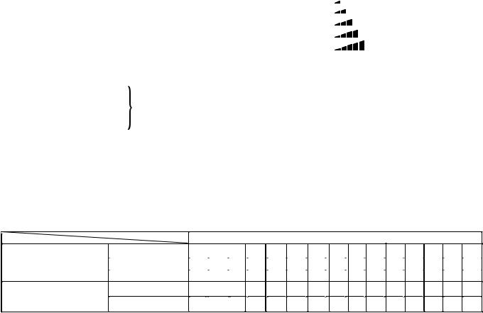
7-2-2. Indoor Fan Control
The operation controls the fan speed at indoor unit
side. The indoor fan (cross flow fan) is operated by the phase control induction motor. The fan rotates in 5
stages in MANUAL mode, and in 5 stages in AUTO mode, respectively. (Table 7-2-2)
1)When setting the fan speed to L, L+, M, M+ or H on the remote controller, the operation is performed with the constant speed shown in Table 7-2-1
Table (7-2-1)
Indication |
Fan speed |
L |
Low |
L+ |
(L + M) / 2 |
M |
Med |
M+ |
(M + H) / 2 |
H |
High |
2)When setting the fan speed to AUTO on the remote controller, revolution of the fan motor is controlled
to the fan speed level shown in Table 7-2-2 according to the setup temperature, room temperature, and heat exchanger temperature.
Table 7-2-2 Indoor fan and air flow rate
Model
|
|
|
|
|
|
|
|
|
FAN TAP |
|
|
|
|
|
|
|
|
|
|
||
OPERATION |
Cooling |
|
UH |
|
H |
|
M+ |
|
|
M |
|
L+ |
|
L |
|
L- |
|
UL |
SL |
|
|
Fan only |
|
|
|
H |
|
M+ |
|
|
M |
|
L+ |
|
L |
|
L- |
|
|
|
|
|
|
MODE |
|
|
|
|
|
|
|
|
|
|
|
|
|
|
|||||||
Dry |
|
|
|
|
|
M+ |
|
|
M |
|
L+ |
|
L |
|
L- |
|
UL |
|
SL |
|
|
|
|
|
|
|
|
|
|
|
|
|
|
|
|
||||||||
RAS-13SKP-ES |
Fan speed (rpm) |
1300 |
1250 |
1160 |
1100 |
1060 |
1000 |
970 |
|
880 |
|
800 |
750 |
700 |
650 |
600 |
|||||
RAS-13SKP-ES(HK) |
|
|
|
|
|
|
|
|
|
|
|
|
|
|
|
|
|
||||
Air flow volume (m3/h) |
620 |
600 |
530 |
490 |
470 |
430 |
420 |
|
360 |
|
320 |
|
290 |
260 |
230 |
200 |
|||||
− 13 −
7-3. Description of Operation Mode
(1)When turning on the breaker, the operation lamp blinks. This means that the power is on (or the power supply is cut off.)
(2)When pressing [ ] button on the
remote control, receiving beep sounds from the indoor unit, and the next operation is performed together with opening the vertical air flow louver.
(3)Once the operation mode is set, it is memorized in the microcomputer so that the previous operation can be effected thereafter simply by pressing
[ ] button.
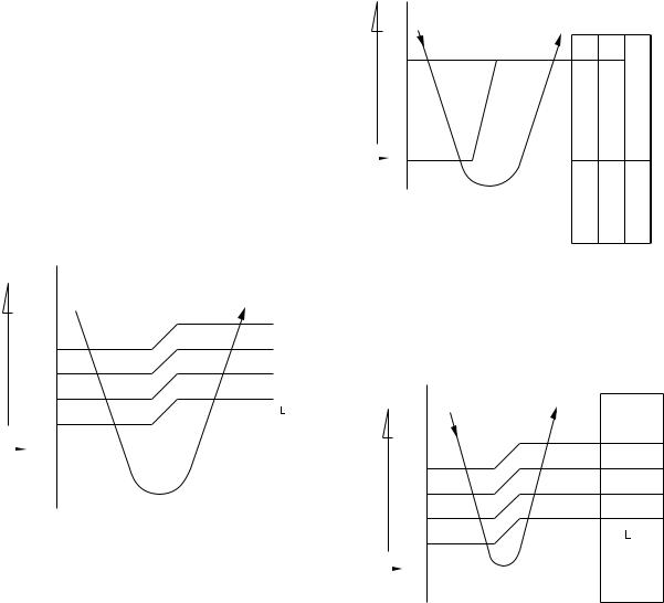
7-3-1. Fan only operation
([MODE] button on the remote control is set to the fan only operation.)
(1)When [FAN] button is set to AUTO, the indoor fan motor operates as shown in Fig. 7-3-1. When [FAN] button is set to LOW, LOW+, MED, MED+ or HIGH, the motor operates with a constant air flow.
temp.) |
|
° C |
|||
+3 |
|
|
|||
−(Preset |
M+ |
||||
+2 |
|||||
|
+2.5 |
*1 |
|
||
|
|
|
|
||
temp.) |
+1.5 |
*2 |
|
||
*3 |
|
||||
(Room |
+0.5 |
|
|
||
Preset |
+1 |
|
|
||
|
0 |
|
|
||
|
|
|
|||
temp. |
|
|
|
|
|
|
|
(Preset temp.: 24 °C) |
|
||
|
|
|
|
|
|
NOTE 1 : *1 : Fan speed = (M + −L) x 3/4 + L *2 : Fan speed = (M + −L) x 2/4 + L *3 : Fan speed = (M + −L) x 1/4 + L
2 : The Hi Power, ECO and COMFORT SLEEP operation can not be set
(Linear approximation from M+ and L)
Fig. 7-3-1 Setting of air flow [FAN:AUTO]
FILE NO. SVM-09028
7-3-2. Cooling operation
([MODE] button on the remote control is set to the cooling operation.)
(1)The compressor, outdoor fan and operation display lamp are controlled as shown in Fig. 7-3-2.
(Presettemp.) |
0.5 |
|
|
° C |
|
(Room temp.) |
|
|
Preset |
|
0 |
|
||
temp. |
|
|
ON ON
OFF OFF ON
Compressor |
Outdoorfan |
OPERATION |
|
|
displaylamp |
Fig. 7-3-2
(2)When [FAN] button is set to AUTO, the indoor fan motor operates as shown in Fig. 7-3-3. When [FAN] button is set to LOW, LOW+, MED, MED+ or HIGH, the motor operates with a constant air flow.
temp.) |
|
° C |
||
+3 |
|
|||
(Preset |
|
M+ |
||
+2.5 |
|
|||
|
|
|||
|
*1 |
|||
− |
+2 |
|
||
*2 |
||||
temp.) |
||||
+1.5 |
|
|||
|
|
|||
|
*3 |
|||
(Room |
+1 |
|
||
+0.5 |
|
|||
|
||||
|
|
|||
Preset |
|
0 |
|
|
|
|
|||
temp. |
-0.5 |
|
||
|
|
|||
NOTE1 : *1 : Fan speed = (M + − L) x 3/4 + L *2 : Fan speed = (M + − L) x 2/4 + L *3 : Fan speed = (M + −L) x 1/4 + L
(Linear approximation from M+ and L)
Fig. 7-3-3 Setting of air flow [FAN:AUTO]
− 14 −
7-3-3. Dry operation
([MODE] button on the remote control is set to the dry operation.)
(1)The compressor, outdoor fan and operation odisplay lamp are controlled as shown in Fig. 7-3-4.
temp.)(Presettemp.) |
|
|
ON:5min. OFF:5min.OFF:4min. |
ON:5min. OFF:4min.OFF:5min. |
|
|
° C |
ON:6min. |
ON:6min. |
|
|
|
|
|
|
||
|
+3 |
|
|
|
|
(Room |
+2 |
|
|
ON |
|
+1 |
|
|
|
||
|
|
|
|
||
|
|
|
OFF |
OFF |
|
Preset |
|
0 |
|
|
|
|
Compressor |
fanOutdoor |
OPERATION |
||
|
|
|
|||
temp. |
|
|
|
|
lampdisplay |
|
|
|
|
|
|
|
|
|
|
|
|
Fig. 7-3-4
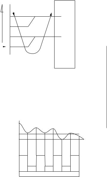
(2)The microprocessor turns the compressor on and off at the regular intervals (4 to 6 minutes). While the compressor is turning off, the indoor fan motor operates in the SUPER LOW position.
The pattern of operation depending on the relation between room temperature and preset temperatures is shown in Fig. 7-3-5.
Room temp.
Preset temp.+1
Preset temp.
ON |
ON |
ON |
|
ON |
||
Compressor |
|
|
|
|
|
|
Outdoor fan |
|
|
|
|
|
|
|
OFF |
|
OFF |
|
OFF |
|
Indoor fan L. |
|
|
|
|
|
|
*S.L. |
L. |
S.L. |
L. |
S.L. |
L. |
|
*Super Low |
|
|
|
|
|
|
Fig. 7-3-5
(3)[FAN] button on the remote control is set to AUTO only.
(4)The ECO, COMFORT SLEEP, QUIET and
Hi POWER operations can not be set.
FILE NO. SVM-09028
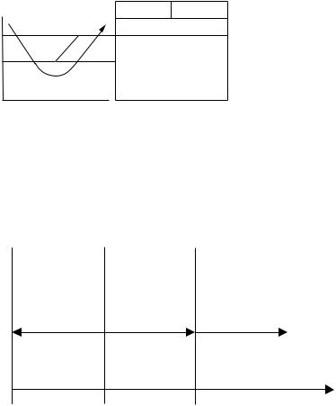
7-3-4. Automatic operation
([MODE] button on the remote control is set to the automatic operation.)
(1)One of 2 operations (Cooling or Fan only)
is selected according to difference between the preset temperature and the room temperature at which the automatic operation has started, as shown in Fig. 7-3-6. The Fan only operation continues until the room temperature reaches a level at which another mode is selected.
(2)Temporary Auto
When the [RESET] button on the indoor unit
is pushed, the preset temperature is fixed at 24°C and the indoor unit is controlled as shown in
Fig. 7-3-6.
°C
temp.) |
|
Cooling operation |
|
|
|
||
−(Presettemp.)(Room |
0 |
|
|
Fan only operation |
|||
|
|||
|
|
||
|
|
|
|
|
|
Fig. 7-3-6 |
– − 15 −–
FILE NO. SVM-09028
7-4. Low-Temperature Limit Control
The microcontroller detects the indoor heat exchanger temperature to prevent the indoor heat exchanger from freezing.The compressor and outdoor fan motor are controlled as shown in Fig. 7-4-1
Heat exchanger |
|
|
temperature |
Compressor Outdoor fan |
|
(°C) |
ON |
|
6 |
||
Less than 2°C continues |
||
|
||
2 |
for 5 minutes |
|
OFF |
||
|
Fig. 7-4-1
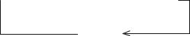
7-5. One-Touch Operation
One touch comfort is the fully automated operation that is set according to the preferable condition in a region.
Fan |
|
|
Operation |
Hi-POWER |
*AUTO/L |
|
|
|
|
|
|
Time after operation |
0 |
|
12 |
|
25 |
|
|
|
starts (min) |
|||
|
|
|
|
|
|
|
|
|
|
|
Fig. 7-5-1
*AUTO/L : Fan operates depends on the setting temperature and room temperature.
During the One Touch Comfort mode if the indoor unit receives any signal with other operation mode, the unit will cancel the comfort mode and operates according to the signal received.
Operation description.
When an indoor unit receives "One Touch Comfort Signal" from the remote controller, the indoor unit operates as following.
1)Air conditioner starts to operation when the signal is received, even if the air conditioner was OFF.
2)Operation mode is set Cooling mode.
3)Target temperature is 22ºC.
4)Louver position is set swing.
5)Fan is controlled as diagram.
–− 16 −–
7-6. Hi POWER Operation
([Hi POWER] button on the remote control is pressed.)
When [Hi POWER] button is pressed while the indoor unit is in Auto or Cooling operation, Hi POWER mark is indicated on the display of the remote control and the unit operates as follows.
(1)Automatic operation
·The indoor unit operates in according to the current operation.
(2)Cooling operation
• The setting temperature drops 3°C.
(The value of the setting temperature on the
remote control does not change.)
• If the room temperature is higher than the setting temperature by 3.5°C or more, the horizontal louver moves to the Hi POWER position automatically. Then when the room temperature is 1°C less than the setting temperature the horizontal louver returns
automatically.
• FAN speed : [AUTO]
If the room temperature is higher than the setting temperature by 3.5°C or more, the air conditioner operates at maximum airflow level. If the room temperature is higher than the setting temperature by less than 3.5°C, the air
conditioner operates at normal airflow level.
• FAN speed : One of 5 levels
If the room temperature is higher than the setting temperature by 3.5°C or more, the air conditioner operates at higher consecutive airflow level. If the room temperature is higher than the setting temperature by less than 3.5°C, the air conditioner operates at normal airflow
level.
· The indoor unit's fan speed level increase 1 tap
(3) The Hi POWER mode can not be set in Dry or Fan only operation.
(4) The Hi POWER mode can memorize with timer function.
FILE NO. SVM-09028
7-7. QUIET Operation
When the [QUIET] button is pressed, the fan of the indoor unit will be restricted the revolving speed at speed L− until the [QUIET] button is pressed once again (cancel Quiet mode).
Quiet mode is the system which, control the revolving speed of indoor fan to work constantly at lower than speed L. In addition, noise level of indoor unit is less than usual.
Remarks :
1. Quiet mode is unable to work in dry mode.
2. Quiet mode is appropriate to work with less cooling load condition. Because of the fan speed L− may cause not enough the cooling capacity.
7-8. ECO Operation
Cooling operation
·The preset temperature will increase 1ºC after the
ECO mode has operated for 1 hour and the temperature will increase another 1ºC after the ECO mode has operated for 2 hour. (the value of the preset temperature on the remote control does not change.)
·The indoor fan speed is depend on presetting and can change every speed after setting ECO operation.
− 17 −
7-9. COMFORT SLEEP Operation
Cooling operation
·The preset temperature will increase 1ºC after the comfort sleep mode has operated for 1 hour and the temperature will increase another 1ºC after
the comfort sleep mode has operated for 2 hour.
(the value of the preset temperature on the remote control does not change)
·Press the [COMFORT SLEEP] button to select this function. The comfort sleep function will be activate together with Auto shut down function. Period of operation time can be selected by re-press the [COMFORT SLEEP] button.
The period of operation time are follows.
 1H
1H  3H
3H  5H
5H  9H
9H
Cancel
The principles of comfort sleep mode are:
·Quietness for more comfortable. When room temperature reach setting temperature.
·Save energy by changing room temperature automatically.
·The air condition can shut down by itself automatically.(follow to operation time that selected)
Remarks :
Comfort sleep mode will not operate in dry mode and fan only mode.
FILE NO. SVM-09028
7-10. FILTER Check lamp
When the elapsed time reaches 1000 hours, the FILTER indicator lights. After cleaning the filters, turn off the
FILTER indicator.
How to Turn Off FILTER Indicator
Press [RESET] button on the indoor unit or press filter button on the remote control.
NOTE :
If [RESET] button is pushed while the FILTER indicator is not lit, the indoor unit will start the automatic operation.
When you want a temporary operation while the FILTER lamp lights, press [RESET] button to turn off the FILTER lamp.
− 18 −
FILE NO. SVM-09028
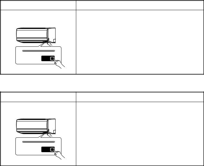
7-11. Auto Restart Function
This indoor unit is equipped with an automatic restarting function which allows the unit to restart operating with the set operating conditions in the event of a power supply being accidentally shut down.
The operation will resume without warning three minutes after power is restored.
This function is not set to work when shipped from the factory. Therefore it is necessary to set it to work.
7-11-1. How to Set the Auto Restart Function
To set the auto restart function, proceed as follows:
The power supply to the unit must be on ; the function will not set if the power is off.
Press the [RESET] button located in the center of the front panel continuously for three seconds.
The unit receives the signal and beeps three times.
The unit then restarts operating automatically in the event of power supply being accidentally shut down.
• When the unit is standby (Not operating)
Operation |
|
Motions |
Press [RESET] button for more than |
The unit is on standby. |
|
three seconds. (Less than 10 seconds) |
↓ |
|
|
|
|
|
The unit starts to operate. |
The green indicator is on. |
↓After approx. three seconds,
The unit beeps three times |
The green indicator blinks |
. |
and continues to operate. |
for 5 seconds. |
Hi POWER FILTER |
PAP |
TIMER OPERATION |
If the unit is not required to operate at this time, press [RESET]
button once more or use the remote controller to turn it off.
RESET
• When the unit is in operation
Operation |
|
Motions |
Press [RESET] button for more than |
The unit is in operation. |
The green indicator is on. |
three seconds. (Less than 10 seconds) |
↓ |
|
|
|
|
|
The unit stops operating. |
The green indicator is turned off. |
↓After approx. three seconds,
|
The unit beeps three times. |
The green indicator blinks |
|
|
for 5 seconds. |
Hi POWER FILTER PAP TIMER OPERATION |
If the unit is required to operate at this time, press [RESET] button |
|
|
||
RESET |
once more or use the remote controller to turn it on. |
|
- 19 -
 Loading...