


INSTALLATION MANUAL
For THERMADOR PROFESSIONAL® Custom Insert
MANUEL D'INSTALLATION
Pour hottes encastrées sur mesure PROFESSIONALmc de THERMADOR
MANUAL DE INSTALACIÓN
Para campanas empotradas a medida PROFESSIONAL® de THERMADOR
Models/
Modèles/
Modelos:
VCIN36JP
VCIN48JP
VCIN54JP
VCIB36JP
VCIB48JP
VCIB54JP

Table of Contents
Safety . . . . . . . . . . . . . . . . . . . . . . . . . . . . . . . . . . . . . . . . . . . . . . . . . . .1
Important Safety Instructions . . . . . . . . . . . . . . . . . . . . . . . . . . . . . . . . . . . . . . . . . . . . . . . . . . . . 1
Advance Planning . . . . . . . . . . . . . . . . . . . . . . . . . . . . . . . . . . . . . . . .3
Before You Begin . . . . . . . . . . . . . . . . . . . . . . . . . . . . . . . . . . . . . . . . . . . . . . . . . . . . . . . . . . . . . 3
General Information . . . . . . . . . . . . . . . . . . . . . . . . . . . . . . . . . . . . . . . . . . . . . . . . . . . . . . . . . . . 4
Installation Preparation . . . . . . . . . . . . . . . . . . . . . . . . . . . . . . . . . . . .6
Ductwork Preparation . . . . . . . . . . . . . . . . . . . . . . . . . . . . . . . . . . . . . . . . . . . . . . . . . . . . . . . . . 7
Electrical Requirements . . . . . . . . . . . . . . . . . . . . . . . . . . . . . . . . . . . . . . . . . . . . . . . . . . . . . . . . 10
Choosing the Correct Blower . . . . . . . . . . . . . . . . . . . . . . . . . . . . . . . . . . . . . . . . . . . . . . . . . . . . 10
Installation Instructions . . . . . . . . . . . . . . . . . . . . . . . . . . . . . . . . . . . .11
Blower Motor Installation . . . . . . . . . . . . . . . . . . . . . . . . . . . . . . . . . . . . . . . . . . . . . . . . . . . . . . . 11
Remote Installation (optional) . . . . . . . . . . . . . . . . . . . . . . . . . . . . . . . . . . . . . . . . . . . . . . . . . . . 15
VCIN Model Installation . . . . . . . . . . . . . . . . . . . . . . . . . . . . . . . . . . . . . . . . . . . . . . . . . . . . . . . . 18
VCIB Model Installation . . . . . . . . . . . . . . . . . . . . . . . . . . . . . . . . . . . . . . . . . . . . . . . . . . . . . . . . 26
Installing Filters, Filter Spacers, & Grease Trays . . . . . . . . . . . . . . . . . . . . . . . . . . . . . . . . . . . . . 28
Service . . . . . . . . . . . . . . . . . . . . . . . . . . . . . . . . . . . . . . . . . . . . . . . . . .29
Before Calling Service . . . . . . . . . . . . . . . . . . . . . . . . . . . . . . . . . . . . . . . . . . . . . . . . . . . . . . . . . 29
Product Data Rating Plate . . . . . . . . . . . . . . . . . . . . . . . . . . . . . . . . . . . . . . . . . . . . . . . . . . . . . . 29
Installer Checklist . . . . . . . . . . . . . . . . . . . . . . . . . . . . . . . . . . . . . . . . . . . . . . . . . . . . . . . . . . . . . 29
To Clean & Protect Exterior Surfaces . . . . . . . . . . . . . . . . . |
. . . . . . . 30 |
THERMADOR® Service, Parts & Accessories. . . . . . . . . . . . |
back page |
This THERMADOR® appliance is made by
BSH Home Appliances Corporation
1901 Main Street, Suite 600
Irvine, CA 92614
Questions?
1-800-735-4328
www.thermador.com
We look forward to hearing from you!
Safety
Important Safety Instructions
READ AND SAVE THESE INSTRUCTIONS
IMPORTANT: Save these Instructions for the local electrical inspector’s use.
INSTALLER: Please leave these Instructions with this unit for the owner. Show the owner the location of the circuit breaker or fuse. Mark it for easy reference.
OWNER: Please retain these instructions for future reference.
 WARNING:
Do not repair or replace any part of the appliance unless specifically recommended in the manuals. Improper installation, service or maintenance can cause injury or property damage. Refer to this manual for guidance. All other servicing should be done by a qualified technician.
 WARNING:
If the information in this manual is not followed exactly, fire or shock may result causing property damage or personal injury.
 WARNING:
Turn off power circuit at service panel and lock out panel before wiring this appliance. Requirement: 120 VAC, 60 Hz 15 A. Allow the appliance to cool after the power has been turned off before servicing the appliance.
 WARNING:
TO REDUCE THE RISK OF FIRE, ELECTRIC SHOCK, OR INJURY TO PERSONS, OBSERVE THE FOLLOWING:
•Use this unit only in the manner intended by the manufacturer. If you have questions, contact the manufacturer at the address or telephone number listed on the back page.
•Before servicing or cleaning unit, switch power off at service panel and lock the service disconnecting means to prevent power from being switched on accidentally. When the service disconnecting means cannot be locked, securely fasten a prominent warning device, such as a tag, to the service panel.
Electric Safety
 WARNING:
IMPROPER GROUNDING CAN RESULT IN A RISK OF ELECTRIC SHOCK.
Consult a qualified electrician if the grounding instructions are not completely understood, or if doubt exists as to whether the appliance is properly grounded. If the power cord is too short, have a qualified electrician install an outlet near the appliance. DO NOT USE AN EXTENSION
CORD.
 WARNING:
Electrical Shock Hazard
•Do not remove ground prong.
•Do not use an adapter.
•Do not use an extension cord.
•Improper grounding can result in a risk of electric shock.
•Failure to follow these instructions can result in death, fire, or electrical shock.
English 1
Important Safety Instructions
READ AND SAVE THESE INSTRUCTIONS
Grounding Instructions:
This appliance must be grounded. In the event of an electrical short circuit, grounding reduces the risk of electric shock by providing an escape wire for the electric current.
Be sure your appliance is properly installed and grounded by a qualified technician. Installation, electrical connections and grounding must comply with all applicable codes.
If required by the National Electrical Code (or Canadian Electrical Code), this appliance must be installed on a separate branch circuit.
To reduce the risk of fire or electric shock, do not use this appliance with any solid-state speed control devices.
Appliance Handling Safety
 CAUTION:
Unit is heavy and requires at least two people or proper equipment to move and install.
Hidden surfaces may have sharp edges. Use caution when handling the appliance. Failure to do so may result in property damage or personal injury.
Related Equipment Safety
Never modify or alter the construction of the appliance. For example, do not remove panels, wire covers or brackets/ screws.
 CAUTION:
For general ventilating use only. Do not use to exhaust hazardous or explosive materials and vapors. To reduce the risk of fire, use only metal ductwork.
When cutting or drilling into wall or ceiling, be careful not to damage electrical wiring and other hidden utilities.
Use a quali¿ed and trained installer.
English 2
Safety Codes and Standards
This appliance complies with one or more of the following Standards:
•UL 858, The Standard for the Safety of Household Electric Ranges
•UL 923, The Standard for the Safety of Microwave Cooking Appliances
•UL 507, The Standard for the Safety of Electric Fans
•UL 1026, The Standard for the Safety of Electric Household Cooking and Food Serving Appliances
•ANSI Z21.1, The American National Standard for Household Cooking Gas Appliances
•CSA C22.2 No. 64, Household Cooking and LiquidHeating Appliances
•CSA C22.2 No. 113, Fans and Ventilators
•CSA C22.2 No. 61, Household Cooking Ranges
It is the responsibility of the owner and the installer to determine if additional requirements and/or standards apply to specific installations.
Ventilation Safety
 WARNING:
TO REDUCE THE RISK OF FIRE, ELECTRIC SHOCK, OR INJURY TO PERSONS, OBSERVE THE FOLLOWING:
•Installation work and electrical wiring must be done by qualified person(s) in accordance with all applicable codes and standards, including fire-rated construction.
•Sufficient air is needed for proper combustion and exhausting of gases through the flue (chimney) of fuel burning equipment to prevent back drafting.
Follow the heating equipment manufacturer's guideline and safety standards such as those published by the National Fire Protection Association (NFPA), and the American Society for Heating, Refrigeration and Air Conditioning Engineers (ASHRAE), and the local code authorities.
•Use only metal ductwork.
•Ducted fans must always be vented to the outdoors. Do not vent exhaust air into spaces within walls, ceilings, attics, crawl spaces or garages.
•When cutting or drilling into wall or ceiling, do not damage electrical wiring and other hidden utilities.
Advance Planning
Before You Begin
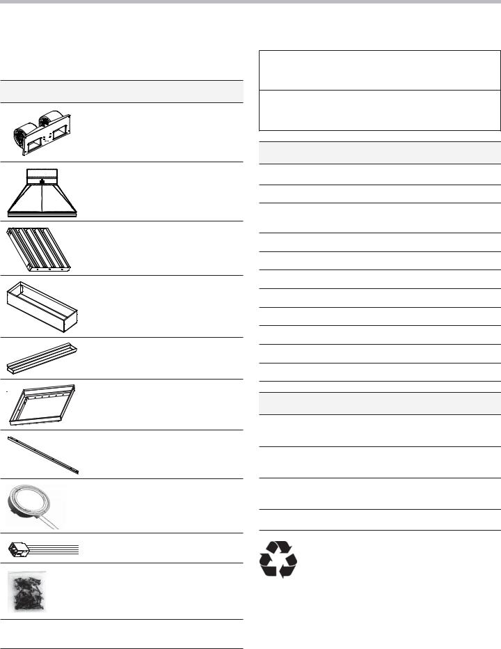
Parts Included
1 – 1000 CFM integral blower (VCIBxxJP models only)
1 – Metal transition with backdraft damper
2, 3, or 4 – Stainless steel baffle filters (depending on model size)
2 – Filter spacers
2 or 3 – Grease trays (depending on model size)
1 – Liner (VCIBxxJP models only)
4 – Side trims (VCINxxJP models only)
2 or 4 – Halogen lights (installed)
1 – Remote blower adaptor
1 – Fastener assortment
Use & Care Guide, Installation Manual, and Registration
Card
 CAUTION:
Before installing, turn power OFF at the service panel. Lock service panel to prevent power from being turned ON accidentally.
Tools and Parts Needed
Blower motor (VCINxxJP models only, see Table 5)
Ductwork as necessary (style varies, see Table 4)
Additional sheet metal screws (as necessary for ductwork installation)
1” (25.4 mm) Strain relief
Aluminum tape (DO NOT use duct tape)
1/2” (13 mm) Conduit if required (follow local codes)
Framing material (as necessary for framework)
Circular saw or jigsaw
Tape measure
Phillips head screwdriver
Protective work gloves
Available Accessories
LINER236 – 36” Custom Hood Liner (VCIN models only)
LINER248 – 48” Custom Hood Liner (VCIN models only)
LINER254 – 54” Custom Hood Liner (VCIN models only)
VCI2REMKS – Remote Control
Remove all tape and packaging before using the appliance. Please, recycle the packaging material, as all THERMADOR® appliance packaging material is recyclable. Never allow children to play with packaging material.
English 3
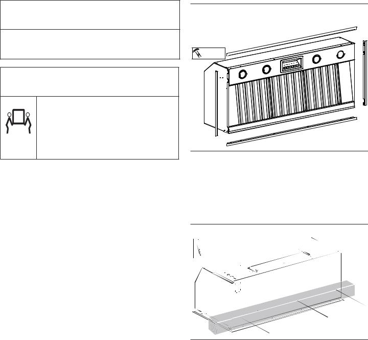
General Information
This manual provides the proper installation instructions for two styles of THERMADOR PROFESSIONAL® custom insert hoods:
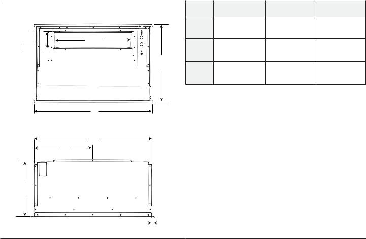
VCINxxJP Overall Dimensions
VCINxxJP — 22” (559 mm) in depth and with widths of 33¾” (857 mm), 45¾” (1,162 mm) or 51¾” (1,315 mm). This model series features brushed stainless-steel filters and halogen lights.
|
|
Top View |
|
|
36” |
48” |
54” |
5 " |
|
|
|
33¾” |
45¾” |
51¾” |
|
|
|
|
|
||||
1 /8 |
|
|
|
A |
(857 mm) |
(1,162 mm) |
(1,315 mm) |
(42mm) |
21¾” |
|
|||||
|
|
||||||
|
|
|
|
16ǩ” |
22ǩ” |
25ǩ” |
|
|
|
(553 mm) |
|
B |
|||
4 /16 |
|
|
(410 mm) |
(562 mm) |
(640 mm) |
||
5 |
" |
|
22” |
|
|
|
|
(110 mm) |
|
|
32Ǫ” |
40Ǫ” |
50Ǫ” |
||
|
|
|
(559 mm) |
C |
|||
|
|
|
|
(822 mm) |
(1,127 mm) |
(1,280 mm) |
|
|
|
|
|
|
|||
A
Rear View
C
B
1213/16”
(325 mm)
11/16” 


 (17 mm)
Table 1: VCIN Custom Insert Overall Dimensions
English 4
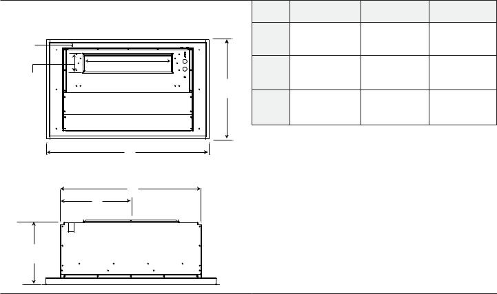
VCIBxxJP Overall Dimensions
VCIBxxJP — 24” (610 mm) in depth and with widths of 41½” (1,054 mm), 52½” (1,334 mm) or 58½” (1,486 mm). This model series features brushed stainless-steel filters, halogen lights, hood liner, and a 1000CFM integral blower.
|
|
|
36 po |
48 po |
54 po |
|
|
Top View |
|
40½” |
52½” |
58½” |
|
15/8" |
|
A |
||||
|
(1,029 mm) |
(1,334 mm) |
(1,486 mm) |
|||
(42mm) |
|
|
|
|
|
|
|
21¾” |
B |
163/16” |
223/16” |
253/16” |
|
5 " |
(553 mm) |
(411 mm) |
(564 mm) |
(640 mm) |
||
24¾” |
||||||
4 /16 |
|
|
|
|
||
(110 mm) |
|
(629 mm) |
32Ǫ” |
44Ǫ” |
50Ǫ” |
|
|
|
|||||
|
|
C |
||||
|
|
(822 mm) |
(1,127 mm) |
(1,280 mm) |
||
|
|
|
A
Rear View
C
B
145/16”
(363 mm)
Table 2: VCIB Custom Insert Overall Dimensions
English 5
Installation Preparation
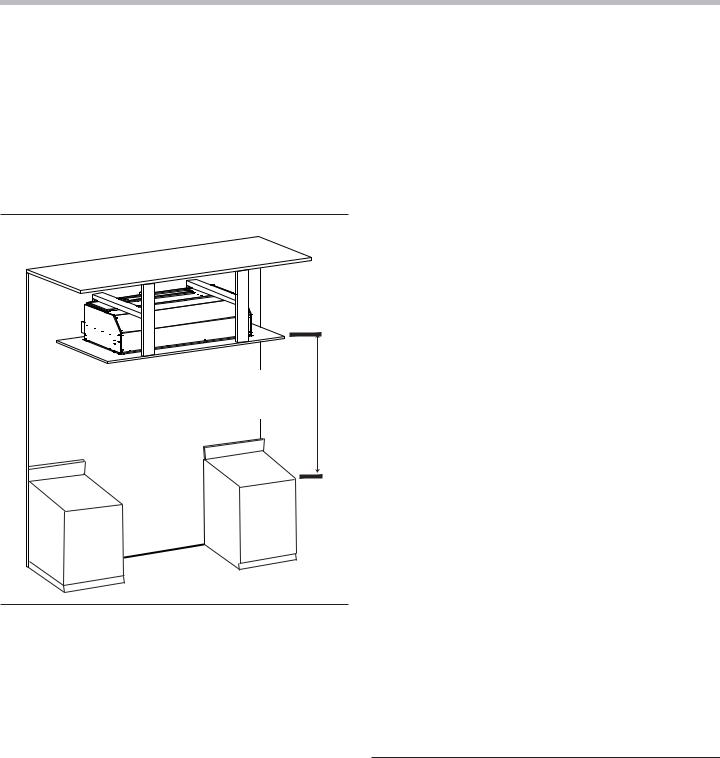
The custom insert unit is designed for installation inside a custom-built hood assembly. It is for ducting to the outside. It cannot be used in conjunction with a recirculation unit.
Hood installation height above a cooktop, rangetop or range can vary. To obtain the necessary installation height above a cooktop, rangetop or range, consult the appliance's installation manual.
Hood Width
The hood width should be no less than the width of the cooking surface. For proper performance, the housing must cover the entire cooking surface.
Where space is not restricted, a wider hood can be used to increase capture area.
30” – 40” (762 – 1,016 mm)
to Countertop
Figure 1: Typical Hood Installation
NOTICE:
The hood could incur some damage from heat if a THERMADOR PROFESSIONAL® series range or rangetop is operated with multiple burners at high settings under a hood that is installed at minimum clearances.
Distance From Cooking Surface
The installation height ranges from a minimum height of 30” (762 mm) to a maximum height of 40” (1,016 mm); however, it is necessary to follow the cooking appliance manufacturer’s installation instructions for proper hood height.
Unit Weight
When calculating the load for the housing support system, be sure to consider the weight of the ventilation unit.
Model |
Weight |
VCIN36JP |
60 lb (27.22 kg) |
|
|
VCIN48JP |
73 lb (33.11 kg) |
|
|
VCIN54JP |
82 lb (37.20 kg) |
|
|
VCIB36JP |
96 lb (43.54 kg) |
|
|
VCIB48JP |
111 lb (50.35 kg) |
|
|
VCIB54JP |
122 lb (55.34 kg) |
|
|
IMPORTANT: |
|
The supplied weights address only the ventilation unit and blower. Installer must account for weight of any materials of construction when calculating the total dead weight load of installation, including but not limited to: wall, tile, mortar, plaster, brick, finishes, partitions, and other similarly incorporated architectural and structural items. It is the responsibility of the owner and the installer to determine if additional requirements and/or standards apply to specific installations.
Table 3: Unit Weight with Blowers
English 6
Ductwork Preparation
Ducting Recommendations
Proper performance is dependent upon proper ducting. Local building codes may require the use of make-up air systems when using ducted ventilation systems greater than speci¿ed cubic feet per minute (CFM) of air movement. The speci¿ed CFM varies from locale to locale. It is the responsibility of the owner and the installer to determine if additional requirements and/or standards apply to specific installations.
DO NOT USE FLEXIBLE DUCT; it creates back pressure/ air turbulence and reduces performance. Always use metal ductwork with a minimum diameter of 6” (150 mm).
Always install a metal vent cover where the ductwork exits the house.
COLD WEATHER installations should have an additional backdraft damper installed to minimize backward cold air flow and a nonmetallic thermal break to minimize conduction of outside temperatures as part of the ductwork. The damper should be on the cold air side of the thermal break. The break should be as close as possible to where the ducting enters the heated portion of the house.
MAKE-UP AIR: Local building codes may require the use of make-up air systems when using ducted ventilation systems greater than specified CFM of air movement. The specified CFM varies from locale to locale. It is the responsibility of the owner and the installer to determine if additional requirements and/or standards apply to specific installations.
For safety reasons, ducting should vent directly outdoors (not into an attic, underneath the house, into the garage or into any enclosed space). The unit cannot be used in conjunction with a recirculation unit.
If using a 10" (254 mm) duct, THERMADOR® recommends not exceeding 150 ft (46 m) of duct.
Keep duct runs as short and straight as possible. Elbows and transitions fittings reduce air flow efficiency. Back to back elbows and “S” turns give very poor delivery and are not recommended.
A short straight length of duct at the inlet of a remote blower gives the best delivery.
Hoods are supplied with a 10" (254 mm) round transition. A locally supplied transition is required for other sizes.
Transitions, elbows and wall or roof caps are all factors that will add more static pressure, therefore increasing your equivalent duct run. For example, assume you have 30 ft (9.2 m) of straight 10" (254 mm) duct with two 90° elbows and an outside wall cap. To calculate the equivalent straight duct run pressure, you would add 12 ft (12.7 m) for each elbow, and 5 ft (1.5 m) for the outside wall cap, increasing your equivalent total run from 30 to 59 ft (9.1 to 17.9 m).
Use Table 4 on page 8 to compute permissible lengths for duct runs to outdoors.
NOTE:
Do not exceed maximum permissible equivalent lengths.
English 7
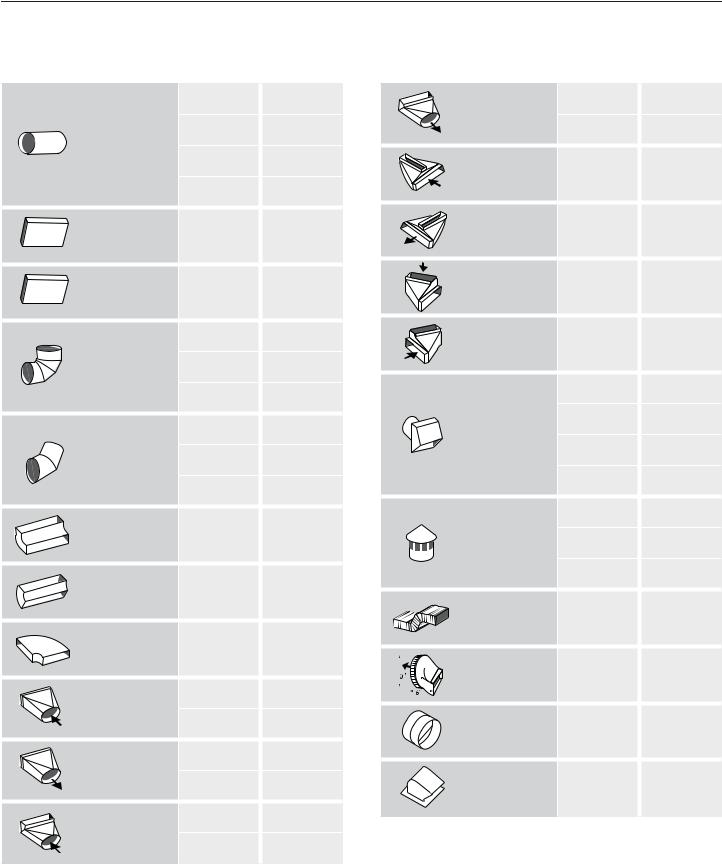
EQUIVALENT DUCT LENGTHS FOR COMMONLY USED TRANSITIONS
Duct Piece |
Size of Duct |
Equivalent |
Duct Piece |
Size of Duct |
Equivalent |
|
Piece (in) |
Length (ft) |
Piece (in) |
Length (ft) |
|||
|
||||||
|
6 |
1.2 |
3¼" x 10" |
6 |
10 |
|
|
|
|
to Round |
|
|
|
Smooth |
7 |
0.95 |
90° Elbow |
7 |
5 |
|
|
|
|
|
|
||
Straight |
8 |
0.7 |
3¼" x 10" |
|
|
|
|
|
|
||||
|
|
|
Center Reverse |
N/A |
15 |
|
|
10 |
0.6 |
Elbow Left |
|
|
|
3¼" x 10" |
|
|
3¼" x 10" |
|
|
|
N/A |
1 |
Center Reverse |
N/A |
25 |
||
Straight |
Elbow Right |
|
|
|||
|
|
|
|
|||
3¼" x 14" |
N/A |
0.7 |
3¼" x 10" Left |
N/A |
15 |
|
Reverse Elbow |
||||||
Straight |
|
|
||||
|
|
|
|
|
||
|
6 |
12 |
3¼" x 10" |
|
|
|
|
Right Reverse |
N/A |
25 |
|||
|
|
|
||||
90° Elbow |
7 |
8 |
Elbow |
|
|
|
Round |
|
|
|
|||
|
|
|
|
|
||
|
8 |
6 |
|
6 |
2 |
|
|
|
|
|
|||
|
6 |
5 |
Round |
7 |
2 |
|
|
|
|
||||
45° Elbow |
|
|
Wall Cap |
8 |
2 |
|
7 |
4 |
|
||||
Round |
|
|
|
|||
|
|
|
10 |
2 |
||
|
|
|
|
83
3¼" x 10" |
|
|
|
|
|
|
|
|
|
6 |
2 |
|
|
|
|
|
|
|
|
|
|
|
|
|
|
90° Elbow |
N/A |
5 |
|
|
|
|
|
|
Round |
7 |
2 |
|
Round |
|
|
|
|
|
|
|
|
Roof Cap |
|
||
|
|
|
|
|
|
|
|
|
|
|
||
3¼” x 10" |
|
|
|
|
|
|
|
|
|
8 |
2 |
|
|
|
|
|
|
|
|
|
|
|
|
|
|
45° Elbow |
N/A |
15 |
|
|
|
|
|
|
2' Long |
|
|
|
Round |
|
|
|
|
|
|
|
|
|
|
|
|
|
|
|
|
|
|
|
|
|
3¼" x 10" |
N/A |
20 |
|
3¼" x 10" |
|
|
|
|
|
|
|
|
Flex |
|
|
|
N/A |
20 |
|
|
|
|
|
|
|
|
|
|
|
Flat Elbow |
|
|
|
|
|
|
|
|
|
|
||
|
|
|
|
|
|
|
|
3¼" x 10" |
10 |
1 |
|
|
|
|
|
|
|
|
|
|
|
|
|||
Round to |
6 |
1 |
|
|
|
|
|
|
to Round |
|
||
|
|
|
|
|
|
|||||||
|
|
|
|
|
|
|
|
|
||||
|
|
|
|
|
|
|||||||
|
|
|
|
|
|
|
|
|
|
|||
|
|
|
|
|
|
|
|
|
|
|||
|
|
|
|
|
|
|
|
|
|
|
|
|
3¼" x 10" |
7 |
1 |
|
|
|
|
|
|
7" Inline |
|
|
|
|
|
|
|
|
|
|
Backdraft |
7 |
|
|
||
|
|
|
|
|
|
|
|
|
|
|
||
|
6 |
5 |
|
|
|
|
|
|
Damper |
|
|
|
3¼" x 10" |
|
|
|
|
|
|
|
|
|
|
||
|
|
|
|
|
|
|
|
3¼" x 10" |
|
|
|
|
to Round |
7 |
3 |
|
|
|
|
|
|
|
|
|
|
|
|
|
|
|
|
|
Roof Jack |
N/A |
|
|
||
|
|
|
|
|
|
|
|
|
|
|
||
|
|
|
|
|
|
|
|
|
and Shutter |
|
|
|
Round to |
6 |
10 |
|
|
|
|
|
|
|
|
|
|
|
NOTE: These commonly used installation parts can be purchased |
|||||||||||
3¼" x 10" |
|
|
|
|||||||||
90° Elbow |
7 |
8 |
|
at a local hardware store. THERMADOR® does not manufacture all |
||||||||
|
|
|
|
these parts. |
|
|
|
|||||
|
|
|
|
|
|
|
|
|
|
|
|
|
|
|
|
|
|
|
|
|
|
|
|
|
|
Table 4: Duct Lengths
English 8
Assembly of the Transition
10” (254 mm) Duct
1” (25.4 mm) screw x2
mm) (445 17½”
3 5/16”
(84 mm)
Figure 2: Transition Dimensions
4 5/16 |
21¾” |
(502 mm) |
(552 mm) |
11¼” |
17½” |
(286 mm) |
(444 mm) |
Figure 3: Transition Cutout
10¼” (260 mm)
1213/16”
(325 mm)
Figure 4: Transition Centerline
1.A minimum height clearance of 10¼” (260 mm) is needed above the hood for transition mounting.
2.Remove transition from inside of hood. Discard brackets attaching transition to the inside of hood.
3.Align mounting holes at base of transition with the mounting holes of the 1/2” (13 mm) flange located at the top or rear of the hood.
4.Fasten transition to hood using two (2) 1” (25.4 mm) sheet metal screws included with hood.
5.Seal connection between transition and hood with aluminum tape. DO NOT use duct tape.
6.Remove tape holding damper closed.
English 9
Electrical Requirements
The unit requires a 120V AC, 60Hz. 15A branch circuit.
The hood should only be connected to a grounded socket that has been installed according to relevant regulations. If possible, place the grounded socket directly behind the chimney paneling. Attach the grounded socket as close to the appliance as possible and in an accessible location.
•The grounded socket should be connected to its own circuit.
•If the grounded socket is no longer accessible following installation of the hood, make sure that an electrical switch is permanently installed for turning off the appliance.
When connected to a GFCI-protected supply, THERMADOR PROFESSIONAL® custom insert hoods are suitable for use in damp locations that are protected from outside weather conditions and not subject to saturation with water and other liquids, but can be subject to moderate degrees of moisture (such as an outdoor covered patio or lanai area). Refer to local codes, NEC/CEC, and or the Authority Having Jurisdiction (AHJ) for additional information.
Check your local building codes for proper method of installation. In the U.S., if there are no applicable local codes, this unit should be installed in accordance with the National Electric Code ANSI/NFPA No. 70, Current Issue. In Canada, installation must be in accordance with the CAN 1- B149.1 and .2 - Installation Codes for Gas Burning Appliances and/or local codes.
The appliance must be grounded. In the event of an electrical short circuit, grounding reduces the risk of electric shock by providing a wire that allows the electric current to escape. This appliance has a cord with a ground wire and grounded plug. The plug must be plugged into an outlet that is properly installed and grounded.
 WARNING:
The appliance must be grounded.
Electrical Data:
Data, including the model and serial number, is located on the product data rating plate inside the appliance, visible after removal of the filter frame (see Figure 40 on page 29).
Choosing the Correct
Blower
A variety of interior and exterior blower options (Remote, Inline or Integral) are available for THERMADOR
PROFESSIONAL® custom insert series hoods. If the unit you have selected does not have a blower included, one must be purchased separately.
Use only THERMADOR® blowers with THERMADOR ventilation hoods. See Table 5: Blower & Circuit Breaker Ratings on page 11, for recommended blowers. Contact Customer Service for additional options (see the back page for contact information).
Blower selection will vary based on the volume of air that needs to be moved and the length and location of the duct run. For long duct runs with multiple turns and bends, consider using a more powerful blower. For the most efficient air-Àow exhaust, use a straight run or as few elbows as possible (refer to “Ductwork Preparation” on page 7).
For indoor grill installations, THERMADOR recommends a minimum of 36" (914 mm) clearance to the bottom of the ventilation unit and Remote or Inline blowers only.
Integral Blowers
These blowers are integrated into the hood at the time of installation (included with the VCIB model units).
Remote Blowers
Depending on preference and ducting situation, these blowers can be mounted on the roof or exterior wall of the home. An exterior installation may be more appealing to reduce noise in the kitchen.
Inline Blowers
To minimize noise in the kitchen, these blowers are mounted along the duct line anywhere between the kitchen and the exterior wall. If there is easy access to duct line (in an attic, for example), this may be an appealing option.
English 10
Installation Instructions
Blower Motor Installation
|
|
|
VOLTAGE |
BLOWER |
CIRCUIT |
|
BLOWER |
SKU |
CFM* |
CURRENT |
BREAKER |
||
(AC) |
||||||
|
|
|
(AMPS) |
(AMPS) |
||
|
|
|
|
|||
|
|
|
|
|
|
|
Integral Blower 600 CFM |
VTN630C |
600 |
120 |
2.7 |
15 |
|
|
|
|
|
|
|
|
Integral Blower 1000 CFM |
VTN1030C |
1000 |
120 |
5.4 |
15 |
|
|
|
|
|
|
|
|
Remote Blower 600 CFM |
VTR630D |
600 |
120 |
4.2 |
15 |
|
|
|
|
|
|
|
|
Remote Blower 1000 CFM |
VTR1030D |
1000 |
120 |
5.7 |
15 |
|
|
|
|
|
|
|
|
Remote Blower 1300 CFM |
VTR1330E |
1300 |
120 |
8.5 |
15 |
|
|
|
|
|
|
|
|
Inline Blower 600 CFM |
VTI610D |
600 |
120 |
4.2 |
15 |
|
|
|
|
|
|
|
|
Inline Blower 1000 CFM |
VTI1010D |
1000 |
120 |
5.7 |
15 |
|
|
|
|
|
|
|
|
* CFM= Cubic feet per minute |
|
|
|
|
|
|
|
|
|
|
|
|
Table 5: Blower & Circuit Breaker Ratings
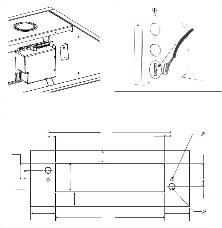
Integral blower installation only
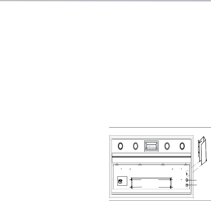
1.The blower is attached to the hood using weld studs provided on the mounting plate. Figure 5 exhibits the weld stud locations.
2.Guide the motor mounting plate over the studs.
3.Attach four (4) nuts (included with hood) to the weld studs. Tighten nuts to secure the blower to the hood.
4.Continue to “Wiring the Hood with an Integral Blower” on page 12.
x4 |
|
Knockouts |
Weld Studs |
behind |
|
|
|
junction |
|
|
box |
Figure 5: Weld Stud & Junction Box Locations
English 11
Wiring the Hood with an Integral Blower
 81/4" (210 mm)
87/8"
(225 mm)

 21/4"
21/4"
(57 mm)
|
63/4" |
41/8" |
67/8" (171 mm) |
(105 mm) |
(175 mm) 25" |
|
(635 mm) |
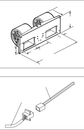
Figure 6: Integral Blower Model VTN1030C
From Blower
From Control Panel
Figure 7: Wiring the Hood with an Integral Blower
Integral Blower models VTN630C and VTN1030C are integrated into the hood at the time of installation (VCIN models). For complete installation instructions see the instructions supplied with the blower unit.
1.Remove junction box channel covering the wires (see Figure 5 on page 11).
2.Remove circular knockouts (Figure 5 on page 11).
3.Connect the blower’s Molex plug connector to the connector present inside the hood, as shown in Figure 7.
4.Install 1” (25.4 mm) conduit connector in junction box.
5.Run black, white, and green wires (#12 AWG) in 1” (25.4 mm) conduit from the power supply to the junction box.
6.Connect the power supply wires to the hood wires in the following order: black to black, white to white, and green wire to green ground screw on chassis. Use spring type wire nuts supplied.
•Lost or missing wire nuts should only be replaced with spring type wire nuts rated for a minimum of two (2) #18 gauge wires and maximum of four (4) #14 gauge wires, UL & CSA rated to 600V and 302°F (150°C.)
7.Close the junction box cover.
English 12
Wiring the Hood with a Remote Blower
|
135/8" |
|
|
21/8" |
(346 mm) |
|
|
(54 mm) 121/8" |
|
||
21/8" |
(308 mm) |
|
|
(54 mm) |
|
|
|
17/8" |
7/ |
|
|
(48 mm) |
dia. 9 8" |
|
|
(251 mm) |
203/4" |
||
|
|||
61/2" |
10" |
(527 mm) |
|
(165 mm) |
(254 mm) |
|
|
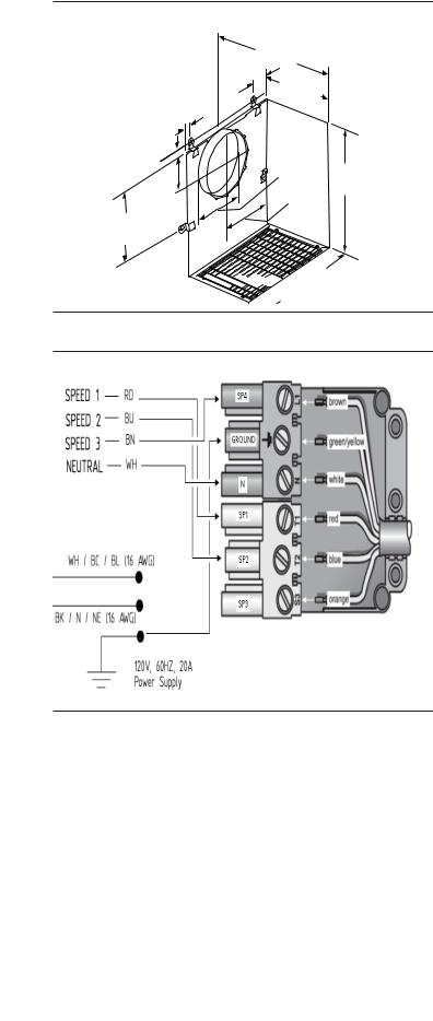
127/8"
(327 mm)


 197/8"
(505 mm)
Figure 8: VTR1330E Remote Blower
Figure 9: Wiring the Hood with a Remote Blower
Custom insert models can be installed with remote blowers (VCIN models). For complete installation instructions see the instructions supplied with the blower unit.
1.Remove junction box channel covering the wires (see Figure 5 on page 11).
2.Remove circular knockouts (Figure 5 on page 11).
3.Install 1” (25.4 mm) conduit connectors.
4.Run black, white, and green wires (#12 AWG) in 1” (25.4 mm) conduit from the power supply to the junction box.
5.Connect the power supply wires to the hood wires in the following order: black to black, white to white, and green wire to green ground screw on chassis. Use spring type wire nuts supplied.
•Lost or missing wire nuts should only be replaced with spring type wire nuts, rated for a minimum of two (2) #18 gauge wires and maximum of four (4) #14 gauge wires, UL & CSA rated to 600V and 302°F (150°C).
6.Connect the “pigtail” to the connector inside the junction box.
7.Run five (5) #14 AWG wires in 1” (25.4 mm) conduit from the remote blower to the second conduit connector.
8.Connect the remote blower to the pigtail wires as per Figure 9. Connect the remote blower green (ground) wire to the ground screw in the junction box. Refer to the blower installation instructions for further wiring details.
9.Close the junction box cover.
English 13

Wiring the Hood with an Inline Blower
121/8" |
|
12" |
|
|
|
|
(305 mm)7/8" (22 mm) |
||||
(308 mm) |
|
||||
|
|||||
|
|
|
|
|
|
|
|
|
|
|
|
|
|
|
|
|
|
|
|
|
|
|
|
|
|
|
|
|
|
|
|
|
|
|
|
ø 97/8" |
191/8" |
(251 mm) |
(486 mm) |
|
13/4" |
|
(44 mm) |
|
127/8" |
|
(327 mm)143/8" |
|
(365 mm) |
|
Figure 10: VTI1010D Inline Blower |
Figure 11: Wiring the Hood with an Inline Blower
Both VCIN and VCIB custom insert models can be installed with inline blowers. For complete installation instructions see the instructions supplied with the blower unit.
1.Remove junction box channel covering the wires (see Figure 5 on page 11).
2.Remove circular knockouts (Figure 5 on page 11).
3.Install 1” (25.4 mm) conduit connectors.
4.Run black, white, and green wires (#12 AWG) in 1” (25.4 mm) conduit from power supply to junction box.
5.Connect the power supply wires to the hood wires in the following order: black to black, white to white, and green wire to green ground screw on chassis. Use spring type wire nuts supplied.
•Lost or missing wire nuts should only be replaced with spring type wire nuts, rated for a minimum of two (2 #18 gauge wires and maximum of four (4) #14 gauge wires, UL & CSA rated to 600V and 302°F (150°C).
6.Connect the “pigtail” to the connector inside the junction box.
7.Run five (5) wires (#14 AWG) in 1” (25.4 mm) conduit from the inline blower to the second conduit connector.
8.Connect the inline blower to the pigtail wires as per Figure 11. Connect the inline blower green (ground) wire to the ground screw in the junction box.
9.Close the junction box cover.
English 14
Remote Control Installation (optional)
NOTE: When using the Custom Insert with remote the unit loses the “AUTO” function and the over-temperature heat sensor described in the Use & Care Guide.
It is recommended that the Remote Control be wired to the hood after the hood is installed.
1.Access wiring
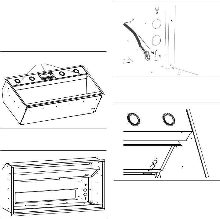
a)Remove filters, spacers and grease trays.
b)Remove the junction box cover (refer to Figure 5 on page 11).
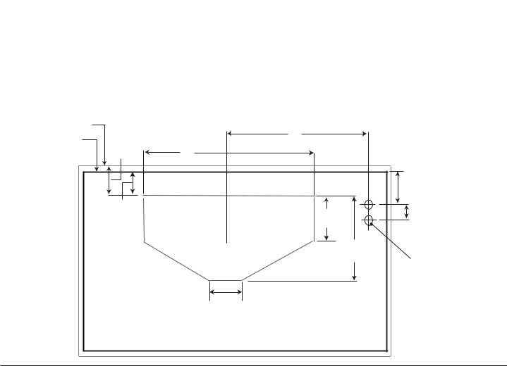
c)Remove three screws holding stainless steel panel to canopy.
Remove 3x screws
2.Connecting the harness to the relay board
a)Insert remote harness end into the mounting hole, as indicated in Figure 14, until it clicks.
Remote
Harness
Harness
Mounting
Hole
Figure 14: Remote Harness Mounting Hole
b) Run harness through core partition hole (Figure 15).
Figure 12: Remove stainless steel panel
d) Remove core partition (Figure 13).
Figure 15: Wire Routing through Partition
c) Unplug harness from the remote control to the relay board (Figure 16).
Figure 13: Remove core partition
English 15
d)Plug in harness included in the remote kit (Figure 16).
e)Connect the extension harness to the connector inside the junction box.
Figure 17: Pigtail Remote Connection
Figure 16: Relay Board Hookup
3. Prepare wall or similar surface for installation as shown below in Figure 18.
|
|
|
|
11¾” |
|
|
|
¼” |
|
|
11/ |
” |
(298 mm) |
11/ ” |
|
|
|
|
|
|
|
(6 mm) |
||||
|
|
16 |
|
16 |
|
|
||
|
|
(17 mm) |
|
(17 mm) |
|
|
|
|
1½” |
|
|
|
3/ ” |
|
|
|
1½” |
(40 mm) |
|
|
|
16 |
|
|
|
(40 mm) |
|
|
|
(5 mm) |
|
|
|
||
|
|
|
|
|
|
|
||
|
|
|
2¾” |
|
|
|
|
|
|
|
(69 mm) |
|
|
|
|
|
|
15/ ” |
|
|
|
|
|
|
|
|
16 |
|
|
|
|
|
|
|
|
(23 mm) |
|
|
3/ ” |
|
|
|
|
5/ ” |
|
|
|
|
|
|
|
||
|
|
|
8 |
|
|
|
|
8 |
|
|
|
(10 mm) |
|
|
|
|
(17 mm) |
|
|
|
|
|
|
|
|
9/ ” |
1 |
|
|
|
103/8” |
1 |
|
|
16 |
3 |
” |
|
3 |
” |
(15 mm) |
|||
|
/8 |
|
(263 mm) |
|
/8 |
|
||
(35 mm) |
|
(35 mm) |
|
|||||
|
|
|
||||||
Figure 18: Wall Cutout (view is shown facing wall)
English 16
4.Connect remote control to extension harness with the included 30 ft (914.4 cm) cable.
5.Insert remote control into cutout. Secure from behind with two (2) nuts onto the weld studs.
Figure 19: Remote Install
6. Reinstall hood components from Figure 12 and Figure 13.
English 17
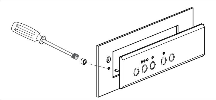
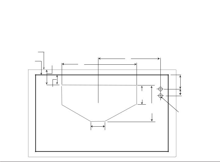
Preparing VCINxxJP Housing Framework
The unit must be mounted to the surrounding housing. See “Installation Preparation” on page 6 for suggestions on determining hood height.
When calculating the load for the housing support system, be sure to include the weight of the ventilation unit. See Table 3 on page 6 for unit weight by model.
Build housing in accordance with the dimensions noted in Figure 20 thru Figure 24.
Model |
A |
|
|
|
|
VCIN36JP |
14 3/16” (360 mm) |
|
|
|
|
VCIN48JP |
19 13/16” (503 mm) |
|
|
|
|
VCIN54JP |
22 13/16” (579 mm) |
|
|
|
|
Back of Trim
Back of Hood |
|
|
A |
|
17/8" |
23” |
|
|
|
(47mm) |
(584mm) |
|
|
|
|
|
|
|
|
|
|
|
|
23/8" |
11/8" |
|
|
|
(86mm) |
|
|
77/8" |
17/8" |
|
(29mm) |
|
|
(48mm) |
|
|
|
|
(200mm) |
|
|
|
|
10¼” |
Diameter |
|
|
|
(260mm) |
|
|
|
|
|
clearance |
|
|
|
|
holes for 1” |
|
3 |
3/ " |
|
(25.4mm) |
|
|
conduit to |
||
|
16 |
|
||
|
(81mm) |
|
junction box |
|
|
|
|
|
|
Figure 20: Transition and Conduit Cutout Dimensions
English 18
Model |
A |
B |
|
|
|
|
|
VCIN36JP |
32 15/16” |
21¼” |
|
(836 mm) |
(540 mm) |
|
|
|
|
||
|
|
|
|
VCIN48JP |
44 15/16” |
21¼” |
|
(1,141 mm) |
(540 mm) |
|
|
|
|
|
|
VCIN54JP |
50 15/16” |
21¼” |
|
(1,294 mm) |
(540 mm) |
|
|
|
|
|
|
B |
A |
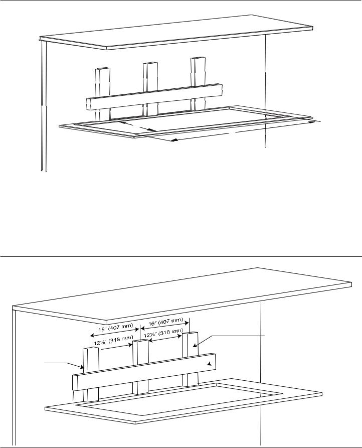
Figure 21: VCIN Cutout Dimensions
To be placed on 16” 
 (407 mm) stud centers
2⅛” (54 mm) 
1½” x 3½” x 12⅛” (38 x 89 x 308 mm)
1½” x 3½” x 44½”  (38 x 89 x 1,130 mm)
Figure 22: VCIN Back Stud Dimensions
English 19
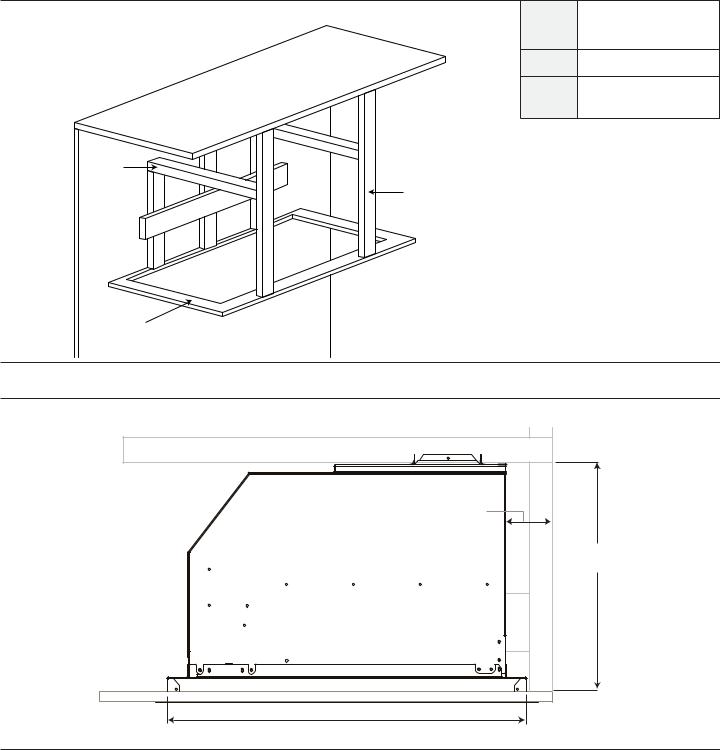
A |
1½” x 3½” x 2713/16” |
|
(38 x 89 x 707 mm) |
||
|
||
B |
ǫ” (16 mm) |
|
C |
1½” x 3½” x 23Ǫ” |
|
(38 x 89 x 594 mm) |
||
|
||
A |
|
|
C |
|
B
Figure 23: VCIN Stud Dimensions
3” (76 mm) 

12¼” (311 mm)
265/16"
(668 mm)
Figure 24: VCIN Side View
English 20
VCINxxJP Installation
Procedure
 WARNING:
To avoid electrical shock hazard, before installing, switch power off at the service panel and lock the panel to prevent the power from being switched on accidentally.
 CAUTION:
The hood weighs at least 60 lbs; therefore, it requires at least two people to lift it safely.
Hidden surfaces may have sharp edges. Use caution when handling the appliance. Failure to do so may result in property damage or personal injury.
1.Turn power OFF at the service panel. Lock service panel to prevent power from being turned ON.
2.Prepare ductwork
a)Refer to “Ductwork Preparation” on page 7.
b)Install metal transition with backdraft damper so that the flap opens up toward the ceiling. If necessary, install thermal break and additional backdraft damper (refer to “Assembly of the Transition” on page 9).
3.Build housing framework
a)Refer to “General Information” on page 4 for the applicable model dimensions.
b)Refer to “Installation Preparation” on page 6 for clearance specifications.
c)Build housing framework for applicable model according to dimensions in “Preparing VCINxxJP Housing Framework” beginning on page 18.
4.Install blower motor
a)Refer to “Choosing the Correct Blower” on page 10.
b)Refer to “Blower Motor Installation” beginning on page 11.
5.Install hood trim
a)Hold trim flush to the bottom of the housing. Secure the trim to the hood with eighteen (18) x ½” (12.7 mm) screws, as indicated in Figure 25.


 ½” (12.7 mm)
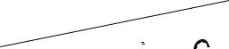

 x18
x18 


Figure 25: VCIN Trim Installation
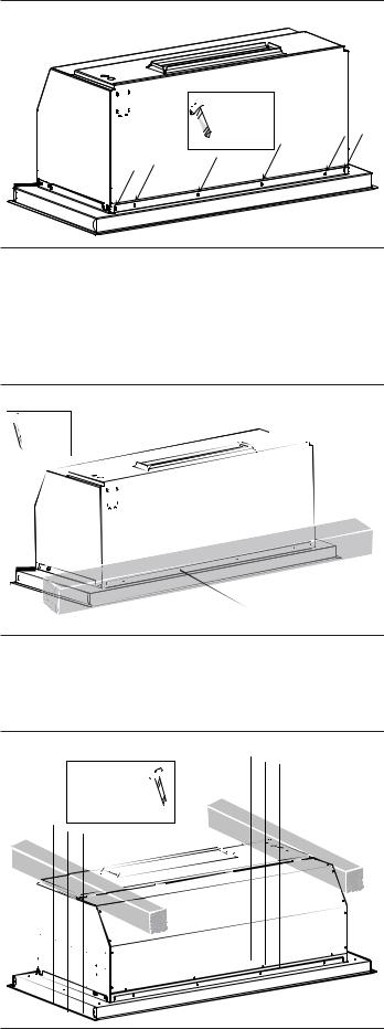
6.Install the unit
a)Install the custom insert inside the custom hood.
b)Secure to the rear of the housing framework using six (6) x 2” (50.8 mm) mounting screws, as indicated in Figure 26.


 2” (50.8 mm)
 X6 mounting
  screws
Figure 26: VCIN Rear Screws
English 21
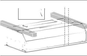
c)Secure to the sides of the housing framework using six (6) x 2” (50.8 mm) mounting screws, 3 per side as indicated in Figure 27.
2” (50.8 mm) 

 mounting screws
  X3 per side
Figure 27: VCIN Side Screws
7.Connect to ductwork
8.Connect electric
a)Remove the junction box cover (see Figure 5 on page 11).
b)Remove circular knock-out holes located on back side of the insert (see Figure 5 on page 11).
c)Connect wiring for applicable blower motor (see blower instructions beginning on page 11).
d)Ensure all controls are in the OFF position. Plug electrical cord into grounded outlet.
9.Install hood filters, filter spacers, and grease trays
a)Refer to “Installing Grease Trays, Filter Spacers, and Filters” on page 28.
10.Test the installation
a)Test the operation of the blower and the lights.
b)Be sure to check for backdraft. With the blower on high, close the windows and doors to the area to ensure that fan does not cause back drafting in any outlet vent for another appliance.
English 22
Preparing VCIBxxJP Housing Framework
The unit must be mounted to the surrounding housing. See “Installation Preparation” on page 6 for suggestions for determining hood height.
When calculating the load for the housing support system, be sure to include the weight of the ventilation unit. See Table 3 on page 6 for unit weight by model.
Build housing in accordance with the dimensions noted in Figure 28 thru Figure 32.
Model |
A |
|
|
|
|
VCIB36JP |
14 3/16” (360 mm) |
|
|
|
|
VCIB48JP |
19 13/16” (503 mm) |
|
|
|
|
VCIB54JP |
22 13/16” (579 mm) |
|
|
|
|
Back of Liner
Back of Hood |
33/16" |
23” |
|
A |
|
|
|
(81mm) |
|
|
|
|
|
|
(584mm) |
|
|
|
|
|
|
|
|
|
|
|
|
|
|
|
|
|
|
23/8" |
|
11/8" |
|
|
|
|
(86mm) |
|
|
|
7/ " |
17/8" |
||
|
(29mm) |
|
|
|||
|
|
|
|
7 |
8 |
(48mm) |
|
|
|
|
(200mm) |
||
|
|
|
|
|
||
|
|
|
|
|
10¼” |
Diameter |
|
|
|
|
|
(260mm) |
|
|
|
|
|
|
clearance |
|
|
|
|
|
|
|
|
|
|
|
|
|
|
holes for 1” |
|
|
|
3/ " |
|
|
(25.4mm) |
|
|
3 |
|
|
conduit to |
|
|
|
16 |
|
|
||
|
|
(81mm) |
|
|
junction box |
|
Figure 28: Transition and Conduit Cutout Dimensions
English 23
B |
A |
Model |
A |
B |
|
|
|
|
|
VCIB36JP |
39¾” (1,010 mm) |
23Ǭ” (606 mm) |
|
|
|
|
|
VCIB48JP |
51¾” (1,315 mm) |
23Ǭ” (606 mm) |
|
|
|
|
|
VCIB54JP |
57¾” (1,467 mm) |
23Ǭ” (606 mm) |
|
|
|
|
|
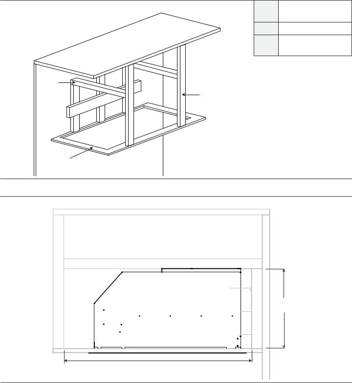
Figure 29: VCIB Cutout Dimensions
To be placed on 16” 
 (407 mm) stud centers
6⅛”  (165 mm)
1½” x 3½” x 16⅛” (38 x 89 x 410 mm)
1½” x 3½” x 44½”  (38 x 89 x 1,130 mm)
Figure 30: VCIB Back Stud Dimensions
English 24
A |
1½” x 3½” x 2713/16” |
|
|
(38 x 89 x 707 mm) |
|
B |
ǫ” (16 mm) |
|
C |
1½” x 3½” x 23Ǫ” |
|
(38 x 89 x 594 mm) |
||
|
||
A |
|
|
C |
|
B
Figure 31: VCIB Stud Dimensions
3” |
(76mm) |
265/16" |
(668mm) |
163/8" (416mm)
Figure 32: VCIB Side View
English 25

VCIBxxJP Installation
Procedure
 WARNING:
To avoid electrical shock hazard, before installing, switch power off at the service panel and lock the panel to prevent the power from being switched on accidentally.
 CAUTION:
The hood weighs at least 60 lbs; therefore, it requires at least two people to lift it safely.
Hidden surfaces may have sharp edges. Use caution when handling the appliance. Failure to do so may result in property damage or personal injury.
1.Turn power OFF at the service panel. Lock service panel to prevent power from being turned ON.
2.Prepare ductwork
a)See “Ductwork Preparation” on page 7.
b)Install metal transition with backdraft damper so that the flap opens up toward the ceiling. If necessary, install thermal break and additional backdraft damper (refer to “Assembly of the Transition” on page 9).
3.Build housing framework
a)Refer to “General Information” on page 4 for the applicable model dimensions.
b)Refer to “Installation Preparation” on page 6 for clearance specifications.
c)Build housing framework for applicable model according to dimensions in “Preparing VCIBxxJP Housing Framework” beginning on page 23.
4.Install blower motor
a)Refer to “Blower Motor Installation” beginning on page 11.
5.Hood liner installation
a)Slide the liner onto the hood (Figure 34).
b)Hold liner flush to the bottom of the housing. Secure the liner to the hood with eighteen (18) x ½” (12.7 mm) screws, as indicated in Figure 35 and
Figure 36.
Figure 33: VCIB Liner
Figure 34: VCIB Liner Installation
½" (12,7 mm) x3 cada lado
Figure 35: VCIB Secure Liner Sides
English 26


 ½” (12.7 mm)
  X6 each front & back side
Figure 36: VCIB Secure Liner Front & Back
6.Install the Unit
a)Install the custom insert inside the custom hood.
b)Secure to the rear of the frame using six (6) 2” (50.8 mm) mounting screws provided (Figure 37).


 2” (50.8 mm)
 X6 mounting
  screws
Figure 37: VCIB Rear Screws
c)Secure to the sides of the frame using six (6) 2” (50.8 mm) mounting screws provided (Figure 38).
2” (50.8 mm)  mounting screws
 X3 per side
Figure 38: VCIB Side Screws
7.Connect to Ductwork
8.Connect Electric
a)Remove the junction box cover (see Figure 5 on page 11).
b)Remove circular knock-out holes located on back side of the insert (see Figure 5 on page 11).
c)Connect wiring for blower motor (see blower instructions beginning on page 11).
d)Ensure all controls are in the OFF position. Plug electrical cord into grounded outlet.
9.Install Hood Filters and Grease Trays
a)Refer to “Installing Grease Trays, Filter Spacers, and Filters” on page 28.
10.Test the installation.
a)Test the operation of the blower and the lights.
b)Be sure to check for backdraft. With the blower on high, close the windows and doors to the area to ensure that fan does not cause back drafting in any outlet vent for another appliance.
English 27
 Loading...