

Page 1
552_Q
tekmarNet® Thermostat 552
Quick Setup Guide
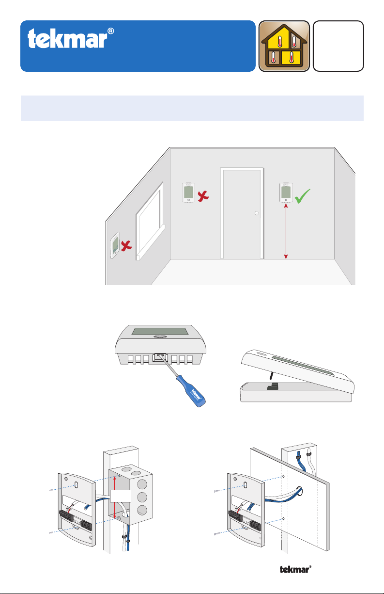
1. Location
Behind
Door
Exterior
Wall
2. Remove Mounting Base
Zoning
02/14
Replaces: 12/13
Interior
Wall
5 feet
1.5 m
3. Install Mounting Base
3 1/4”
(83 mm)
Stud
Switch
Box
1
Thermostat
Base
A Watts Water Technologies Company
Thermostat
Base
Stud
Wall
© 2014 552_Q - 02/14
Page 2
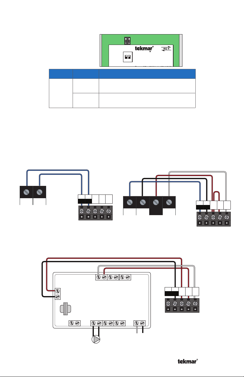
4. Switch Settings
Switch
5. Wiring
tN2 tN2
To tN2 device
Back of
Thermostat
Position
ON
1
OFF
tekmarNet®2
tN4
tN2
tN2
Thermostat
123
1051-03
1051-03
Switch
Settings
ON
Lock
ON
Setback
1
ck
itch Settings:
lock
tekmarNet
tNt 552
None
Scene
One Stage Heat
Thermostat 552
One Stage Heat
2
www.tekmarcontrols.com
ed
ol Master 1
Mmm YYYY
Lot # 12345
/
Action
LOCK Access level adjustment is not
available.
UNLOCK Access level adjustment is
available.
C
R
Rh W1
tN4 C W
R
To tN4 device
/
tekmarNet®4
C
tN4
R
tN2
tN2
Rh W1
Thermostat
Standalone - Switching Relay
24 V
Com
Switching Relay
Zone 1
A Watts Water Technologies Company
W
W
R
(T)(T)
Zone 2 Zone 3
HNXX HNHN NL
Pump
R
W
R
(T)(T)
(T)(T)
NL
2
C
tN4
R
tN2
tN2
Rh W1
Thermostat
© 2014 552_Q - 02/14
Page 3
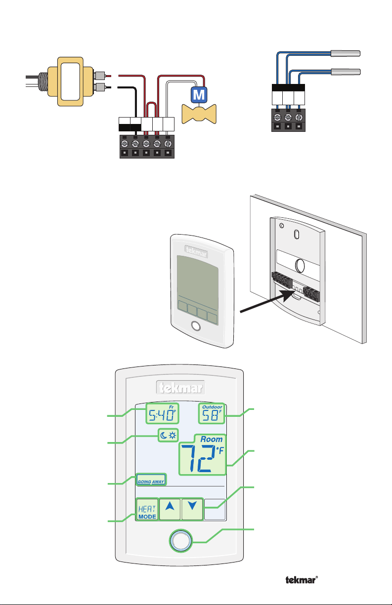
5. Wiring (Continued)
Standalone - Zone Valve
Sensors
L
N
24 V (ac)
Transformer
R
C
C
tN4
R
tN2
tN2
Rh W1
Thermostat
6. Install Thermostat
Thermostat
7. User Interface
Valve
Front
No Power
S1 S2
Com
Thermostat
Thermostat
Push
Base
Adjust
the Time
Adjust the
Schedule
Away Key
Turn the
Heat on
or Off
A Watts Water Technologies Company
Home
Button
Display the
Floor or Outdoor
temperature
Room
Temperature
Adjust the Temperature
Home Button.
Return to the ‘Home’
Screen from any menu.
Press and hold for 3
seconds to access the
programming menus
3
© 2014 552_Q - 02/14
Page 4
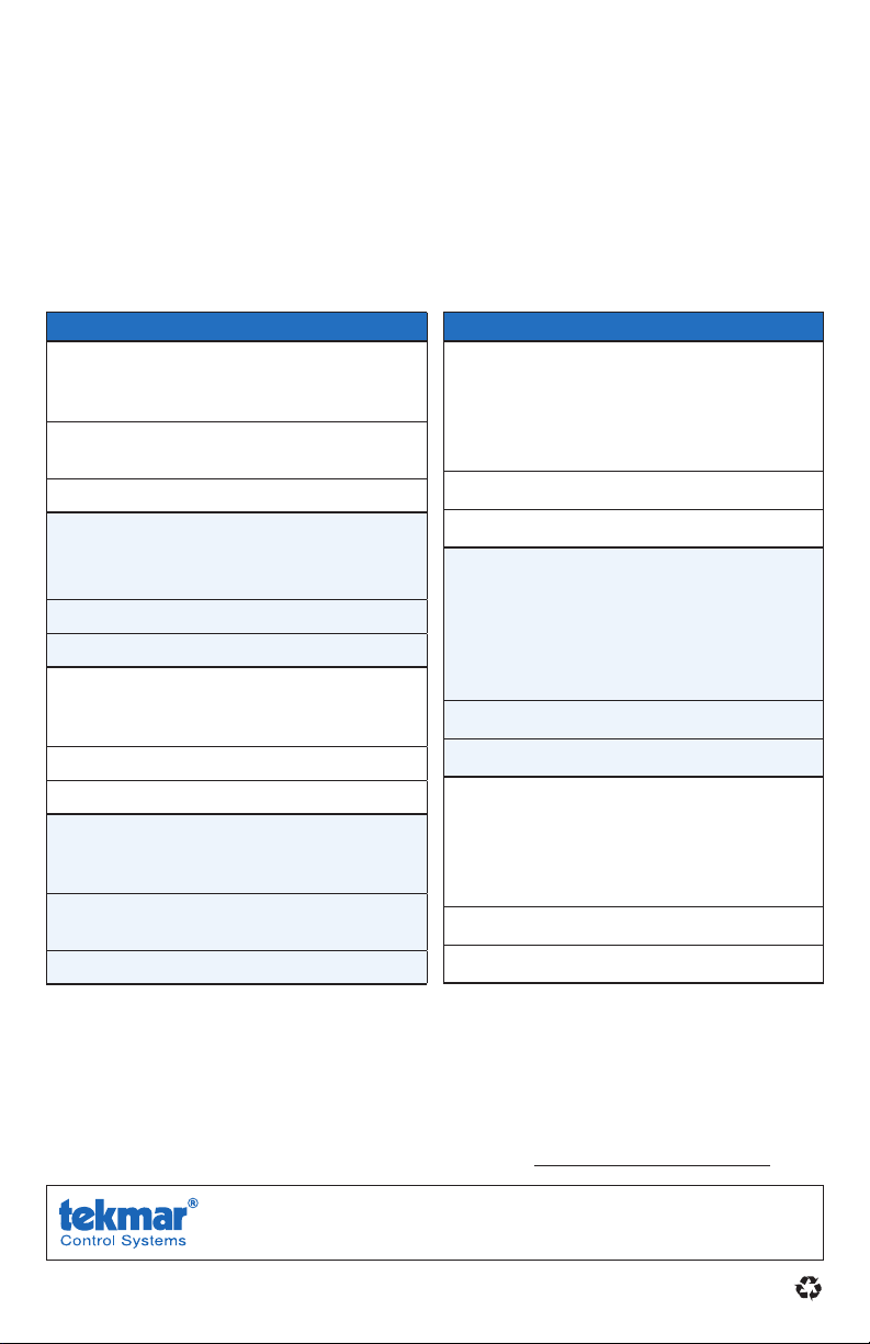
8. Critical Settings
The following settings are essential to the successful operation of the system.
Step 1:
room to Unlock to change Access level to Installer. Return to Lock setting once installation
has been completed.
Step 2: Press and hold “Home” button for 3 seconds to enter programming menus.
Step 3: Touch NEXT to locate the Setup Menu and touch ENTER.
Set switch setting #1 and tekmarNet® system control located in the mechanical
Setup Menu Settings
SENSOR 1
Select to the type of sensor connected to
auxiliary sensor input 1.
Range: OFF, ROOM, FLOR (floor), OUT
(outdoor)
Default: OFF
SENSOR 2
Select to the type of sensor connected to
auxiliary sensor input 2.
Range: OFF, ROOM, FLOR (floor)
Default: OFF
ROOM SENSOR
Select whether the built-in room
temperature sensor is on or off.
Range: OFF or ON
Default: ON
W1 TERMINAL UNIT
Select the terminal unit type of the first
stage of heat W1.
Range: CTRL, HRF1, HRF2, CONV,
COIL, OTHR
Default: CTRL
Setup Menu Settings
W1 PUMP
Select whether the boiler system pump
or mix system pump on a tekmarNet
®
system control should operate while the
first stage of heat W1 is operating.
Range: OFF or ON
Default: ON
W1 THERMAL MOTOR
Select whether the first stage of heat W1
operates a thermally actuated zone valve
(wax actuator). When set to ON, there is a
3 minute delay before operating the pump
and any heat sources.
Range: OFF or ON
Default: OFF
W CYCLES PER HOUR
Select the number of heating cycles
per hour. Only available when the
thermostat is not connected to a
tekmarNet
®
System Control.
Range: SYNC, AUTO, 2 to 12
Default: SYNC
For a full list of settings and operational details, please refer to the thermostat
Installation and Operation Manual (552_D) included with compatible
tekmarNet® controls or download the brochure from www.tekmarcontrols.com
Product design, software and literature are Copyright ©2014 by tekmar Control Systems Ltd.,
A Watts Water Technologies Company. Head Offi ce: 5100 Silver Star Road, Vernon, B.C.
Canada V1B 3K4, 250-545-7749, Fax. 250-545-0650
All specifications are subject
to change without notice
4 552_Q - 02/14.
Web Site
: www.tekmarControls.com
Page 5

552_Q
tekmarNet® Thermostat 552
Guide d'installation rapide
1. Emplacement
Derrière
porte
Mur extérieur
2. Retirez la base de montage
Zonage
Mur intérieur
5 pi.
1,5 m
02/14
Remplace: 12/13
3. Installez la base de montage
Goujon
3 1/4”
(83 mm)
Stud
Commutateur
Switch
Box
Base de
Thermostat
thermostat
Base
Une Entreprise de Watts Water Technologies
boîte
5
Base de
Thermostat
thermostat
Base
© 2014 552_Q - 02/14
Wall
Mur
Goujon
Stud
Page 6

4. Réglages des commutateurs
Dos du
thermostat
Commutateur Position Action
ON
1
OFF
5. Filage
tekmarNet®2
C
tN4
tN2
tN2 tN2
Au dispositif tN2
tN2
Thermostat
123
1051-03
1051-03
Switch
Settings
ON
Lock
ON
Setback
1
ck
itch Settings:
lock
tekmarNet
tNt 552
None
Scene
One Stage Heat
Thermostat 552
One Stage Heat
2
www.tekmarcontrols.com
ed
ol Master 1
Mmm YYYY
/
Lot # 12345
/
VERROUILLAGE
Le réglage du niveau d'accès n'est pas disponible.
DÉVERROUILLAGE
Le réglage du niveau d'accès est disponible.
tekmarNet®4
R
Rh W1
tN4 C W
R
tN4
tN2
Au dispositif tN4
Thermostat
tN2
C
R
Rh W1
Relais de commutation - Autonome
W
R
24 V
Com
Switching Relay
Relais de commutation
Une Entreprise de Watts Water Technologies
(T)(T)
Zone 1
Zone 2 Zone 3
HNXX HNHN NL
Pump
Pompe
W
R
W
R
(T)(T)
(T)(T)
tN4
tN2
tN2
C
R
Rh W1
Thermostat
NL
6
© 2014 552_Q - 02/14
Page 7

5. Filage (suite)
Zone de Soupape - Autonome
Capteurs
L
N
24 V (ca)
Transformateur
R
C
C
tN4
R
tN2
tN2
Rh W1
Soupape
Thermostat
6. Installer le Thermostat
Façade du
thermostat
Thermostat
Poussoir
No Power
Pas d’alimentation
S1 S2
Com
thermostat
Base de
7. Interface d’utilisateur
Régler
l’heure
Régler le
programme
Clè à
distance
Activer ou
déactiver la
chaleur
Une Entreprise de Watts Water Technologies
Home
7
Afficher la
température au sol
ou à l’extérieure
Température de la
chambre
Régler la température
Bouton daccueil. Revenir à
l’écran «Home» (Accueil)
depuis n’importe quel menu.
Appuyez et maintenez
enfoncé pendant 3
secondes pour accéder aux
menus de programmation
© 2014 552_Q - 02/14
Page 8

8. Paramètres critiques
Les paramètres suivants sont essentiels au bon fonctionnement du système.
Étape 1: Définir le réglage du commutateur sur #1 et le système de contrôle tekmarNet
situé dans la salle mécanique sur Déverrouiller pour changer le niveau d'accès à
l'installateur. Retour pour Verrouiller réglage, une fois l'installation terminée.
Étape 2: Appuyez et maintenez le bouton «Home» pendant 3 secondes pour entrer
dans les menus de programmation.
Étape 3: Touchez SUIVANT pour localiser le menu de configuration et appuyez sur
ENTRER.
®
Réglages du menu de configuration
CAPTEUR 1
Sélectionner le type de capteur relié à
l'entrée auxiliaire du capteur 1.
Gamme: OFF, CHAMBRE, FLOR (étage),
OUT (en plein air)
Par défaut: OFF
CAPTEUR 2
Sélectionner le type de capteur relié à
l'entrée auxiliaire du capteur 2.
Gamme: OFF, CHAMBRE, FLOR (étage)
Par défaut: OFF
CAPTEUR DE CHAMBRE
Sélectionnez si le capteur intégré de
la température ambiante est allumé ou
éteint.
Gamme: OFF ou ON
Par défaut: ON
UNITÉ DU TERMINAL W1
Sélectionner le type d'unité du terminal
de la première étape de chauffage W1.
Gamme: CTRL, HRF1, HRF2, CONV,
COIL, OTHR (AUTRE)
Par défaut: CTRL
Réglages du menu de configuration
POMPE W1
Selectionnez soit la pompe du système de
la chaudière ou la pompe du système de
mélange du système de tekmarNet
®
doit
fonctionner pendant la première étape de
fonctionnement de chauffage W1.
Gamme: OFF ou ON
Par défaut: ON
MOTEUR THERMIQUE W1
Sélectionner si la première étape de
chauffage de W1 active une soupape
de zone actionnée thermiquement
(actuateur a cire). Lorsqu'elle est activée,
il ya un délai de 3 minutes avant de faire
fonctionner la pompe et n’importe quelle
sources de chaleur.
gamme: OFF ou ON
Par défaut: OFF
W CYCLES PAR HEURE
Sélectionnez le nombre de cycles de
chauffage par heure. Uniquement
disponible lorsque le thermostat
n'est pas connecté à un Système de
Contrôle tekmarNet
®
.
Gamme: SYNC, AUTO, 2 à 12
Par défaut: SYNC
Pour une liste complète des paramètres et les détails opérationnels, s’il vous plaît
se référer à l’installation du thermostat et mode d’emploi (552_D) inclus avec
les compatible tekmarNet
®
contrôles ou télécharger la brochure depuis
www.tekmarcontrols.com
Co nc ep tio n d e pr od uit , l ogi ci el e t l it tér at ure so nt d es d ro it s ré se rvé s © 2014 pa r te kma r C ont ro l Sy st ems
Ltd.,
Une Entreprise de Watts Water Technologies. Bureau Prin cipal: 5100 Silver Star Road, Ver non,
B.C. Canada V1B 3K4, 250-545-7749, Téléc: 250-545-0650
Toutes spécifications sont sujettes à changements
sans préavis. Imprim
é
au Canada.
8 552_Q - 02/14.
Site Web
: www.tekmarControls.com
Page 9

552_Q
tekmarNet® Thermostat 552
Guía de instalación rápida
1. Ubicación
Detrás
de la puerta
Pared
exterior
2. Quite la base de montaje
División en
zonas
02/14
Remplazado
por: 12/13
Pared
interior
5 pies
1,5 m
3. Instalación de la base de montaje
3 1/4”
(83 mm)
Stud
Caja de
Switch
interruptor
Box
Base del
Thermostat
termostato
Base
9
© 2014 552_Q - 02/14
Base del
Thermostat
termostato
Base
Una Compañía de Watts Water Technologies
Pared
Wall
Stud
Page 10

4. Ajustes del interruptor
Parte trasera
del termostato
Interruptor
1
5. Cableado
tekmarNet®2
tN2 tN2
tN2 control de zones
1051-03
1051-03
Switch
Settings
Posición Acción
LOCK (BLOQUEADO) el nivel de
ON
acceso para ajustes se encuentra
bloqueado.
UNLOCK (DESBLOQUEADO) el
OFF
nivel de acceso para ajustes se
encuentra disponible.
C
tN4
R
tN2
tN2
Rh W1
Termostato
123
ON
Lock
ON
Setback
1
ck
itch Settings:
lock
tekmarNet
tNt 552
None
Scene
One Stage Heat
Thermostat 552
One Stage Heat
2
www.tekmarcontrols.com
ed
ol Master 1
Mmm YYYY
Lot # 12345
/
tekmarNet®4
tN4 C W
R
tN4 control de zones
/
C
tN4
R
tN2
tN2
Rh W1
Termostato
Relé de acoplado – Independiente
W
24 V
Com
Switching Relay
Relé de acoplado
Zone 1
HNXX HNHN NL
Bomba
Una Compañía de Watts Water Technologies
R
W
R
(T)(T)
(T)(T)
Zone 2 Zone 3
Pump
10
W
R
(T)(T)
tN4
tN2
tN2
C
R
Rh W1
Termostato
NL
© 2014 552_Q - 02/14
Page 11

5. Cableado (continuación)
Válvula de zona – Independiente
Sensores
L
N
24 V (ca)
Transformador
R
C
C
tN4
R
tN2
tN2
Rh W1
Válvula
Termostato
6. Instalación del termostato
Frente del
termostato
7. Interfaz del usuario
No Power
S1 S2
Com
Termostato
Eempuje
Base del
termostato
Ajustar
hora
Ajustar la
programación
Tecla de
salida
Prender o
apagar la
calefacción
Una Compañía de Watts Water Technologies
Home
Mostrar la
temperatura del
Piso o del Exterior
Temperatura
ambiente
Ajustar la temperatura
Botón Inicio. Vuelva a
la pantalla inicial desde
cualquier otro menú.
Mantenga presionado por
3 segundos para acceder
al menú del programa
11
© 2014 552_Q - 02/14
Page 12

8. Ajustes críticos
Las siguientes configuraciones son esenciales para que el sistema trabaje de manera correcta.
Paso 1: Desbloquee (opción UNLOCK) el ajuste número uno del interruptor y del control
del sistema tekmarNet® para cambiar el nivel de accesibilidad a Instalador. Cámbielo
nuevamente a Bloquear (opción Lock) luego de finalizar la instalación.
Paso 2: Mantenga presionado el botón “Home” por 3 segundos para ingresar a los menús
de programación.
Paso 3: Presione el botón NEXT (SIGUIENTE) para localizar el menú de SETUP (Instalación)
y presione ENTER (ENTRAR).
Ajustes del menú de instalación
SENSOR 1
Seleccione el tipo de
sensor
conectado
a la entrada número 1 para sensor
auxiliares.
Rango: OFF (Apagado), ROOM
(Ambiente), FLOR (Piso), OUT (Exterior)
Predeterminado: OFF (Apagado)
SENSOR 2
Seleccione el tipo de
sensor
conectado
a la entrada número 2 para sensor
auxiliares.
Rango: OFF (Apagado), ROOM
(Ambiente), FLOR (Piso),
Predeterminado: OFF (Apagado)
SENSOR AMBIENTE
Prenda o apague el
sensor
integrado de
la temperatura del aire en el ambiente.
Rango: OFF (Apagado) o ON (Encendido)
Predeterminado: ON (Encendido)
TIPO DE TERMINAL W1
Seleccione el tipo de terminal de la
primera etapa de calefacción W1.
Rango: CTRL, HRF1, HRF2, CONV,
COIL, OTHR
Predeterminado: CTRL
Ajustes del menú de instalación
BOMBA W1
Seleccione si la bomba del sistema de
caldera o una bomba de sistema mixto
en un control de sistema tekmarNet
se accionará mientras se encuentre
en funcionamiento la primera etapa de
calentamiento W1.
®
Rango: OFF (Apagado) o ON (Encendido)
Predeterminado: ON (Encendido)
MOTOR TÉRMICO W1
Seleccione si la primera etapa W1 de
calentamiento opera una válvula térmica
de zona (actuador de cera). Cuando se
encuentra en ON (encendido), hay un
retraso de 3 minutos antes de accionar
la bomba o cualquier tipo de fuente de
calefacción.
Rango: OFF (Apagado) o ON (Encendido)
Predeterminado: OFF (Apagado)
CICLOS W POR HORA
Seleccione el número de ciclos de
calentamiento por hora.Solamente
disponible cuando el termostato no se
encuentra conectado a un control de
sistema tekmarNet
®
.
Rango: SYNC (Sincronizar), AUTO, 2 a 12
Predeterminado: SYNC (Sincronizar)
Para una lista completa de ajustes y detalles funcionales, por favor diríjase al Manual de
instalación y manejo del termostato (552_D) incluido en los controles compatibles tekmarNet
o descargue el folleto informativo en www.tekmarcontrols.com
El diseño del producto, software y la literatura poseen derechos reservados ©2014 a nombre de tekmar
Contro l Systems Ltd., Una Compañía d e Watts Water Tec hnologi es Ofi cin a Pri nci pal: 5100 S ilve r St ar Ro ad,
Vernon, B.C. Canadá V1B 3K4, 250-545-7749, Fax. 250-545-0650 Sitio web: www.tekmarControls.com
Todas las especificaciones pueden cambiar
sin previo aviso.
12 552_Q - 02/14.
®
 Loading...