


Teka COCINAS CRISTAL-GAS CG Lux-60 4G. Al AL, COCINAS CRISTAL-GAS CG.1 3G. 1P CG Lux-60 4G., COCINAS CRISTAL-GAS CG.1 4G, COCINAS CRISTAL-GAS CGC 4G, COCINAS CRISTAL-GAS CG Lux-70 5G TR User Manual
...Installation and maintenance man
COCINAS CRISTAL-GAS CG.1 4G / CG.1 3G. 1P
CG Lux-60 4G. / CG Lux-70 4G. / CG Lux-70 4G AI AL
CG Lux-70 5G. / CG Lux-60 4G. Al AL / CG Lux-70 5G. Al AL
CG Lux-70 5G AI TR AL / CG Lux-70 5G TR / CGC 4G / CGC 4G AI AL
CG Lux-75 2G AI TR AL / CG Lux-86 3G AI TR AL
CG Lux-86 2G 1P AI TR AL
User’s Guide to this Instruction Manual
Dear Customer, |
Safety Instructions |
Thank you forTEKAchoosing a |
hob. |
We are sure that our product will fully satisfy your requirements.
This modern, functional and practical appliance has been built using top quality materials which are subjected to strict quality controls throughout the manufacturing processN.B. .
Before installing or using our product, we recommend you to carefully read this manual and to follow its instructions step by step in order to obtain the best possible results.
Keep this instruction manual in a safe place so that you can consult it whenever necessary and comply with the warranty requirements.
To benefitWarrantyfrom our you must present proof of purchase together with the warranty certificate.
Before using your hob for the first tim read the installation and connectio tions.
These hob models can be installe same kitchenTEKA units as ovens an panels.
To avoid the risk of burns, keep away from the hob during or after i tion.
We recommend you to follow our ins and that the installation of our hobs out by our Technical Service personn
2

Contents
Introduction |
Page 4 |
4 |
Description of the Appliance |
||
Installation |
9 |
9 |
Positioning of the hobs |
|
|
Positioning of the oven |
|
10 |
Anchoring of the hob |
|
10 |
Connecting the hob to the oven or |
11 |
|
the control panel |
|
|
Gas Connection |
|
12 |
Electrical Connection |
|
13 |
Gas transformation |
|
14 |
Technical Information |
16 |
16 |
Dimensions and powers |
|
|
Technical Data |
|
18 |
Rating Plates |
|
20 |
Use and Maintenance |
24 |
24 |
Special requirements before first use |
||
Component Parts of Gas Burners |
24 |
|
Lighting of Burners |
|
24 |
Switching on Electric Hotplates |
26 |
|
Components of a Safety System |
27 |
|
Using your Hob |
|
29 |
Hints for the correct Usage of Burners |
29 |
|
Hints for the correct Usage of |
29 |
|
Electric Hotplates |
|
|
Reminder |
|
30 |
Cleaning and Conservation |
31 |
|
Electric Hotplates (Mod. CG. 1 3G 1P) |
32 |
|
Maintenance |
|
32 |
If Something Doesn´t Work |
33 |
Introduction
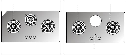
Description of the Appliance
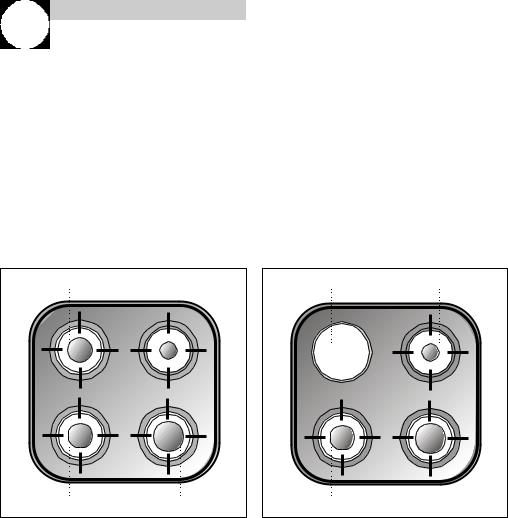
CG. 1 4G |
(see drawing 1) |
CG.1 3G. 1P. |
(see drawing 2) |
1 |
Auxiliary burner of 860 Kcal/h - 1 kW. |
Auxiliary burner of 860 Kcal/h - 1 |
|
2 |
Semi fast burner of 1,5002 Kcal/h - |
High -power hotplate of 1, |
|
|
1.75 kW. |
|
Ø 145 mm. |
3 |
Fast burner of 2,550 Kcal/h - 3 3kW |
Semi fast burner of 1,500 |
|
4 |
Semi fast burner of 1,500 Kcal/h - |
1.75 kW. |
|
|
1.75 kW. |
4 |
Fast burner of 2,550 Kcal/h - 3 k |
|
• All burners incorporate a pan support. |
• All burners incorporate a pan sup |
|
|
• Maximum calorific power: 6,400 Kcal/h - |
• Maximum calorific power: 4,900 |
|
|
7.5 kW. |
|
5.75 kW. |
|
|
|
• Maximum electric power: 1,500 W |
2 |
1 |
2 |
1 |
4 |
3 |
3 |
4 |
Drawing 1 |
D |
4
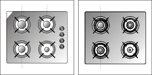
CG-Lux-60 4G. and CG Lux-60 4G AI AL |
|
CGC 4G(seeand CGC 4G AI AL |
(see draw |
|||||
|
drawing 3) |
|
|
|
1 |
|
Fast burner of 2,580 Kcal/h - 3 k |
|
1 |
Fast burner of 2,580 Kcal/h - 3 2kW. |
- |
Semi fast burner of 1,500 |
|||||
2 |
Semi fast |
burner |
of |
1,500 |
Kcal/h |
1.75 kW. |
|
|
|
1.75 kW. |
burner |
of |
1,500 |
3 |
- |
Semi fast burner of 1,500 |
|
3 |
Semi fast |
Kcal/h |
1.75 kW. |
|
||||
|
1.75 kW. |
|
|
|
4 |
|
Auxiliary burner of 860 Kcal/h - 1 |
|
4 |
Auxiliary burner of 860 Kcal/h - 1 kW. |
|
• All burners incorporate a pan sup |
|||||
5 |
Burner controls. |
|
|
|
|
• Maximum calorific power: 6,450 |
||
|
|
|
|
|
|
|
7.5 kW. |
|
•All burners incorporate a pan support.
•Maximum calorific power: 6,450 Kcal/h - 7.5 kW.
1 |
3 |
1 |
2 |
2 |
4 |
3 |
4 |
|
Drawing 3 |
|
D |
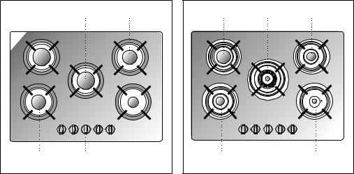
CG-Lux-70 5G., and CG Lux -70 5G AI AL |
CG-Lux(See-70 5G TR and CG Lux -70 5G AI TR AL |
||
|
drawing 5) |
|
(See drawing 6) |
1 |
Fast burner of 2,580 Kcal/h - 3 1kW. |
Fast burner of 2,580 Kcal/h - 3 k |
|
2 |
Fast burner of 2,580 Kcal/h - 3 2kW. |
Triple ring burner of 3,000 |
|
3 |
Semi fast burner of 1,500 Kcal/h - |
3.5 kW. |
|
|
1.75 kW. |
3 |
Semi fast burner of 1,500 |
4 |
Semi fast burner of 1,500 Kcal/h - |
1.75 kW. |
|
|
1.75 kW. |
4 |
Semi fast burner of 1, 500 |
5 |
Auxiliary burner of 860 Kcal/h - 1 kW. |
1.75 kW. |
|
6 |
Burner controls. |
5 |
Auxiliary burner of 860 Kcal/h - 1 |
|
|
6 |
Burner controls. |
|
• All burners incorporate a pan support. |
• All burners incorporate a pan sup |
|
|
• Maximum calorific power: 9,020 Kcal/h - |
• Maximum calorific power: 9,450 |
|
|
10.5 kW. |
|
11 kW. |
1 |
2 |
3 |
1 |
2 |
3 |
4 |
6 |
5 |
4 |
6 |
5 |
|
|
Drawing 5 |
|
|
D |
6
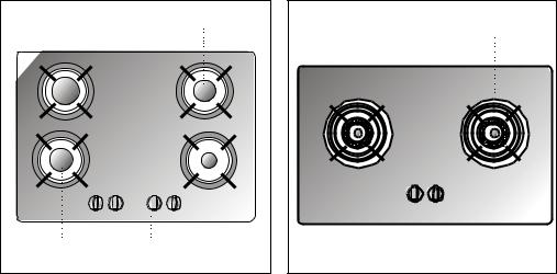
CG-Lux-70 4G and CG Lux -70 4G AI |
AL |
CG-Lux-75 2G AI TR AL |
(See drawing |
||||
|
(See drawing 7) |
|
|
1 |
|
Triple ring burner of 3,010 |
|
1 |
Fast burner of 2,580 Kcal/h - 3 kW. |
- |
3.5 kW. |
|
|||
2 |
Semi fast |
burner |
of |
1,500 2Kcal/h |
Triple ring burner of 3,010 |
||
|
1.75 kW. |
burner |
of |
1,500 3Kcal/h |
- |
3.5 kW. |
|
3 |
Semi fast |
Burner controls. |
|
||||
|
1.75 kW. |
|
|
|
|
• All burners incorporate a pan sup |
|
4 |
Auxiliary burner of 860 Kcal/h - 1 kW. |
|
|||||
5 |
Burner controls. |
|
|
|
• Maximum calorific power: 6,020 |
||
|
|
|
|
|
|
7 kW. |
|
•All burners incorporate a pan support.
•Maximum calorific power: 6,450 Kcal/h - 7.5 kW.
1 |
|
3 |
1 |
2 |
2 |
5 |
4 |
|
3 |
|
|
Drawing 7 |
|
D |
CG-Lux-86 3G AI TR AL |
burner |
(See drawingCG9)-Lux-86 2G 1P AI TR AL |
(See draw |
||||
1 |
Triple ring |
of |
3,0101 Kcal/h |
- |
Triple ring burner of 3,010 |
||
|
3.5 kW. |
burner |
of |
3,0102Kcal/h |
- |
3.5 kW. |
|
2 |
Triple ring |
Triple ring burner of 3,010 |
|||||
|
3.5 kW. |
burner |
of |
1,5003Kcal/h |
- |
3.5 kW. |
|
3 |
Semi fast |
High-power hotplate of 1,500 W, Ø |
|||||
|
1.75 kW. |
|
|
4 |
|
Burner controls. |
|
4 |
Burner controls. |
|
|
|
• All burners incorporate a pan sup |
||
|
• All burners incorporate a pan support. |
|
• Maximum calorific power: 6,020 |
||||
|
• Maximum calorific power: 7,520 Kcal/h - |
7 kW. |
|
||||
|
8.75 kW. |
|
|
|
|
• Maximum electric power: 1,500 W |
|
1 |
3 |
2 |
1 |
3 |
2 |
|
4 |
Drawing 9 |
|
4 |
Dr |
|
|
|
|
8

Installation
Important |
|
INSTALLATION AND ADJUSTMENT MUST BE |
|
CARRIED OUT BY AUTHORISED TECHNICAL |
|
PERSONNEL ACCORDING TO THE APPLICABLE |
A |
INSTALLATION REGULATIONS. |
Positioning of the hobs
Depending on the model to be installed an aper- |
|
ture will be made in the worktop, of the dimen- |
B |
sions specified in the drawing 11. A template is |
|
included in the packaging of models CG.1 4G. |
|
and CG.1 3G. 1P. for the correct sizing of the |
|
aperture for these two hob models. |
C |
If the hob is installed above kitchen storage |
|
units (cupboards, drawers, etc.), an interme- |
|
diate panel must be fitted. |
|
2 |
For hobs with controls, its location must |
|
D |
|
include a ventilation slot at the front, of 110 |
|
|
||
|
cm . In this case the minimum distance bet- |
|
|
|
|
ween the lower part of the hob and the upper |
|
|
|
|
par t of the furniture below the hob will be 20 |
|
|
|
|
mm. If there is no front ventilation slot, the |
|
|
|
|
minimum distance between the hob and the |
|
E |
|
|
upper part of the furniture must be 130 |
|
|
|
|
mm.The hob must be installed at least at 10 |
|
|
|
|
cm from its sides to any wall in the room. |
|
|
|
|
The minimum vertical distance of the lower |
|
|
|
|
part of the piece of furniture placed above the |
|
|
|
|
hob will be 600 mm. |
A |
Mod.: CG Lux-60 y CGC 4G |
Dr |
|
The piece of furniture where the hob with oven |
|||
|
is to be placed will be properly fixed. |
B |
Mod.: CG.1 3G. 1P. y CG.1 4G. |
|
|
|
C |
Mod.: CG Lux-70 |
|
|
|
D |
Mod.: CG Lux-75 |
|
|
|
E |
Mod.: CG Lux-86 |
|
* In the case of the granite hob the rement can be 580 mm.
Positioning of the oven
See the applicable manual.
In the cases of the models CG.1 4G 3G 1P, the clamps must be fitted as the picture 13, depending on the thi the furniture.
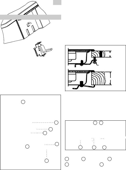
Anchoring of the hob
Once the hob position has been dimensioned, |
For worktops 30 mm thick or less, us |
|||||
the seal (J) must be affixed to the lower part |
screws supplied as complementary fi |
|||||
of the cooker. This is fastened by means of |
introducing them into the circular ho |
|||||
four clamps (G), each of which has two tabs |
clamp. A fillet shall form in this ho |
|||||
(P) which are inserted in the apertures (O) in |
screw is introduced in it. This operati |
|||||
the hob until they click into place. To secure |
be done before fastening the clamps t |
|||||
the clamp, open the tab (S) outwards a little |
|
|
|
|
|
|
as indicated in the figure. Once the seal and |
|
|
|
20/30 mm. |
||
the clamps have been positioned the applian- |
|
|
|
|||
ce may be installed in its position. |
|
|
Self-tapping screw |
|||
Use a screwdriver to tighten the screws (T) on |
|
|
||||
the four clamps and the hob will be perfectly |
|
|
worktops of 20 an |
|||
|
|
mm. wide |
||||
secured in place. (See drawing 12). |
|
|
|
40 mm. |
||
N.B. It is imperative to install the seal under |
|
|
|
|
|
Dra |
the brim of the worktop. Failure to install this |
|
|
|
|
|
|
may cause the worktop to be exposed to high |
|
|
|
|
|
|
|
|
|
|
|
|
|
temperatures. |
|
To install hob model CGC 4G AI AL, i |
||||
J |
|
|||||
|
quick-fix nuts in the screw housings |
|||||
|
|
wing 14), connect the clip which cor |
||||
|
|
ponds with the height measureme |
||||
|
|
hob unit (20, 30 and 40 mm) and ti |
||||
|
|
screws until they are well secure. |
||||
|
O |
|
|
A |
B |
|
P |
|
C |
D |
20 mm. 30 mm.40 m |
||
|
A |
E |
Dr |
|||
Drawing 12 |
T |
Seal |
B Work top |
E |
C |
|
D |
Fastening clip |
Quick-f |
||||
10
Hob models CG-Lux-75 2G and CG-Lux-86 3G |
If the unit below the hob is to be used |
|||||||||||||
are installed in the same way as the CGC 4G |
products it must be situated at a dista |
|||||||||||||
AI AL, except for the staples which are |
least 10 cm below the hob. Furthermor |
|||||||||||||
geometrically dif ferent. The |
|
installation of |
be taken into account that the tempe |
|||||||||||
these hobs must be carried out in the way |
|
|
o |
|||||||||||
the interior of the furniture may rise to |
||||||||||||||
shown in the drawing 15, depending on the |
|
|
|
|||||||||||
thickness of the work top. |
|
|
|
CONNECTING THE HOB TO THE OVEN |
|
|||||||||
|
|
|
|
|
|
|
|
|
|
|
(Mod. CG.1 4G, CG.1 3G 1P and CGC 4G) OR |
|
||
|
|
|
A |
|
|
B |
|
|
THE CONTROL PANEL |
|
||||
|
|
|
|
|
|
|
|
To connect the hob to the oven, four t |
||||||
|
|
|
|
|
20 mm. |
|
|
|
|
|||||
Drawing 15 |
|
|
|
|
|
|
|
30 |
mm. 40 mm. |
universal joints are provided. (See draw |
||||
|
|
|
|
|
|
|
|
|
||||||
|
|
|
|
|
|
|
|
|
||||||
|
C |
|
D |
|
|
E |
|
|
|
|
||||
|
|
|
|
|
|
|
|
|||||||
A Seal |
B Work top |
|
E |
|
|
C |
Screw |
|
|
A |
||||
D Fastening clip |
|
Quick |
-fix nut |
|
|
|||||||||
CGC 4G |
|
|
|
|
|
|
|
|
|
|
dimensioned, |
|
|
|
Once the hob position has been |
A |
|
|
|||||||||||
the seal must be affixed (J) to the |
hob. |
|
Dra |
|||||||||||
Fix the clamps (K) into the holes on the |
B |
|
||||||||||||
|
|
|
||||||||||||
part of the case, as shown in drawing, |
by tighte- |
|
|
|
||||||||||
ning the four screws supplied (ø4.2 mm). |
To make this connection, proceed as |
|||||||||||||
1
The clamps (K) and seal (J) are supplied in the
packaging along with the hob. (See drawing 16).
2
J
20 |
J |
K |
3 |
4 |
||
|
||
30 |
K |
|
J |
|
|
40 |
|
5 |
|
K |
|
|
|
Drawing 16
Disconnect from the mains supp CG.1 3G 1P and CGC 4G AI AL). Detach the telescopic universal pressing the retention tab (marke using a thin screwdriver and ex extender a few centimetres. Remove the four lockpins from the Partially insert the oven in its positi care not to snag the telescopic joints which are hanging from the u of the hob, and leave sufficient sp able to connect the other ends of to the rods at the rear part of th panel, before finally connecting the For the electrical connection bet two appliances, connect the hob c to the oven connector (mod. CG. and CGC 4G AI AL).
 Loading...