


Teka CG Lux-70 4G AI, CG Lux-60 4G AI, CG Lux-70 5G AI, CG Lux-70 5G AI TR AL, CG Lux-70 5G AI TR User Manual
...61401134/329 ingles 18/7/03 16:55 Página 1
Installation and maintenance manual
CRISTAL-GAS HOBS CG.1 4G / CG.1 3G. 1P
CG Lux-60 4G. / CG Lux-70 4G. / CG Lux-70 4G AI AL CG Lux-70 5G. / CG Lux-60 4G. Al AL / CG Lux-70 5G. Al AL
CG Lux-70 5G AI TR AL / CG Lux-70 5G TR / CGC 4G / CGC 4G AI AL
CG Lux-75 2G AI TR AL / CG Lux-86 3G AI TR AL
CG Lux-60 4G AI / CG Lux-70 4G AI / CG Lux-70 5G AI
CG Lux-70 5G AI TR / CG Lux-75 2G AI TR / CG Lux-86 3G AI TR
Bedienungsanleitung und Pflegehinweise
GASKOCHFELDER TEMPERGLAS CG.1 4G / CG.1 3G. 1P CG Lux-60 4G. / CG Lux-70 4G. / CG Lux-70 4G AI AL CG Lux-70 5G. / CG Lux-60 4G. Al AL / CG Lux-70 5G. Al AL
CG Lux-70 5G AI TR AL / CG Lux-70 5G TR / CGC 4G / CGC 4G AI AL
CG Lux-75 2G AI TR AL / CG Lux-86 3G AI TR AL
CG Lux-60 4G AI / CG Lux-70 4G AI / CG Lux-70 5G AI
CG Lux-70 5G AI TR / CG Lux-75 2G AI TR / CG Lux-86 3G AI TR
Instructions de montage et conseils d’entretien
PLAQUES DE CUISSON CRISTAL-GAZ CG.1 4G / CG.1 3G. 1P CG Lux-60 4G. / CG Lux-70 4G. / CG Lux-70 4G AI AL
CG Lux-70 5G. / CG Lux-60 4G. Al AL / CG Lux-70 5G. Al AL
CG Lux-70 5G AI TR AL / CG Lux-70 5G TR / CGC 4G / CGC 4G AI AL
CG Lux-75 2G AI TR AL / CG Lux-86 3G AI TR AL
CG Lux-60 4G AI / CG Lux-70 4G AI / CG Lux-70 5G AI
CG Lux-70 5G AI TR / CG Lux-75 2G AI TR / CG Lux-86 3G AI TR
61401134/329 ingles 18/7/03 16:55 Página 2
User’s Guide to this Instruction Manual
Dear Customer,
Thank you for choosing a TEKA hob.
We are sure that our product will fully satisfy your requirements.
This modern, functional and practical appliance has been built using top quality materials which are subjected to strict quality controls throughout the manufacturing process.
Before installing or using our product, we recommend you to carefully read this manual and to follow its instructions step by step in order to obtain the best possible results.
Keep this instruction manual in a safe place so that you can consult it whenever necessary and comply with the warranty requirements.
To benefit from our Warranty you must present proof of purchase together with the warranty certificate.
Safety Instructions
Before using your hob for the first time, please read the installation and connection instructions.
These hob models can be installed in the same kitchen units as TEKA ovens and control panels.
N.B. To avoid the risk of burns, keep children away from the hob during or after its operation.
We recommend you to follow our instructions and that the installation of our hobs be carried out by our Technical Service personnel only.
If you detect any breakage or craking in the hob glass, switch all the burner controls to the off position (‘0’), turn off the gas connection and disconnect the electricity supply.
2
61401134/329 ingles 18/7/03 16:55 Página 3
Contents
Introduction |
Página 4 |
|
Description of the Appliance |
|
4 |
Installation |
|
9 |
Positioning of the hobs |
|
9 |
Positioning of the oven |
|
10 |
Anchoring of the hob |
|
10 |
Connecting the hob to the oven or the |
|
|
control panel |
|
11 |
Gas Connection |
|
12 |
Electrical Connection |
|
13 |
Gas transformation |
|
14 |
Technical Information |
|
16 |
Dimensions and powers |
|
16 |
Technical Data |
|
18 |
Rating Plates |
|
20 |
Use and Maintenance |
|
24 |
Special requirements before first use |
24 |
|
Component Parts of Gas Burners |
|
24 |
Lighting of Burners |
|
24 |
Switching on Electric Hotplates |
|
26 |
Components of a Safety System |
|
27 |
Using your Hob |
|
28 |
Hints for the Correct Usage of Burners |
29 |
|
Hints for the Correct Usage of Electric |
|
|
Hotplates |
|
29 |
Reminder |
|
30 |
Cleaning and Conservation |
|
31 |
Electric Hotplates (MOD. CG.1 3G. 1P) |
32 |
|
Maintenance |
|
32 |
If Something Doesn’t Work |
|
33 |
3
61401134/329 ingles 18/7/03 16:55 Página 4
Introduction
Description of the Appliance
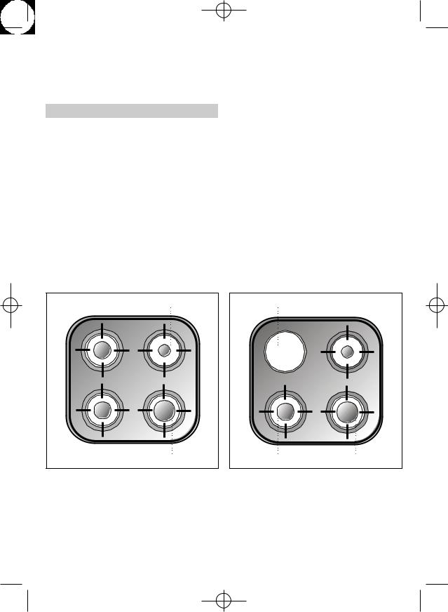
CG. 1 4G (See drawing 1) |
CG.1 3G. 1P. (See drawing 2) |
||
1 |
Auxiliary burner of 860 Kcal/h - 1 kW. |
1 |
Auxiliary burner of 860 Kcal/h - 1 kW. |
2 |
Semi fast burner of 1,500 Kcal/h - |
2 |
High -power hotplate of 1,500 W, |
|
1.75 kW. |
|
Ø 145 mm. |
3 |
Fast burner of 2,580 Kcal/h - 3 kW |
3 |
Semi fast burner of 1,500 Kcal/h - |
4 |
Semi fast burner of 1,500 Kcal/h - |
|
1.75 kW. |
|
1.75 kW. |
4 |
Fast burner of 2,580 Kcal/h - 3 kW. |
• All burners incorporate a pan support. |
• All burners incorporate a pan support. |
||
• Maximum calorific power: 6,400 Kcal/h - |
• Maximum calorific power: 4,900 Kcal/h - |
||
|
7.5 kW. |
|
5.75 kW. |
|
|
• Maximum electric power: 1,500 Watts. |
|
2 |
1 |
2 |
1 |
4 |
3 |
3 |
4 |
|
Drawing 1 |
|
Drawing 2 |
4
61401134/329 ingles 18/7/03 16:55 Página 5
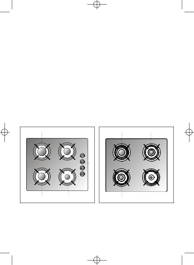
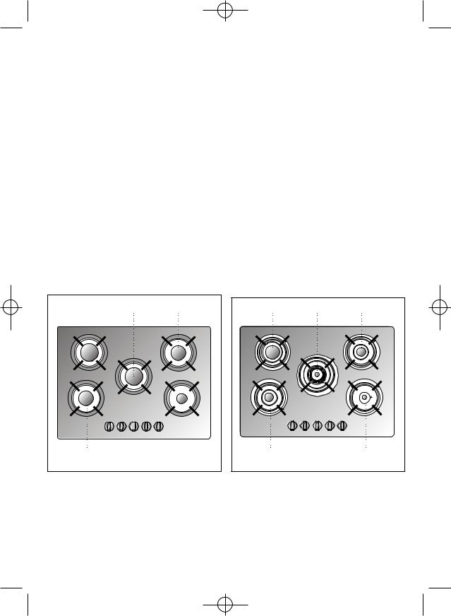
CG-Lux-60 4G, CG Lux-60 4G Al AL |
CGC 4G and CGC 4G AI AL (See drawing 4) |
||
and CG Lux-60 4G AI (See drawing 3) |
|
|
|
1 |
Fast burner of 2,580 Kcal/h - 3 kW. |
1 |
Fast burner of 2,580 Kcal/h - 3 kW. |
2 |
Semi fast burner of 1,500 Kcal/h - |
2 |
Semi fast burner of 1,500 Kcal/h - |
|
1.75 kW. |
|
1.75 kW. |
3 |
Semi fast burner of 1,500 Kcal/h - |
3 |
Semi fast burner of 1,500 Kcal/h - |
|
1.75 kW. |
|
1.75 kW. |
4 |
Auxiliary burner of 860 Kcal/h - 1 kW. |
4 |
Auxiliary burner of 860 Kcal/h - 1 kW. |
5 |
Burner controls. |
• All burners incorporate a pan support. |
|
|
|
• Maximum calorific power: 6,450 Kcal/h - |
|
• All burners incorporate a pan support. |
|
7.5 kW. |
|
•Maximum calorific power: 6,450 Kcal/h - 7.5 kW.
1 |
3 |
|
|
|
|
1 |
2 |
|
|
5 |
|
2 |
4 |
|
|
|
|
3 |
4 |
|
|
Drawing 3 |
Drawing 4 |
5
61401134/329 ingles 18/7/03 16:55 Página 6
CG-Lux-70 5G., CG Lux-70 5G Al AL |
CG-Lux-70 5G TR , CG Lux-70 5G AI TR AL |
|||
and CG Lux -70 5G AI (See drawing 5) |
and CG Lux -70 5G AI TR (See drawing 6) |
|
||
1 |
Fast burner of 2,580 Kcal/h - 3 kW. |
1 |
Fast burner of 2,580 Kcal/h - 3 kW. |
|
2 |
Fast burner of 2,580 Kcal/h - 3 kW. |
2 |
Triple ring burner of 3,000 Kcal/h |
- |
3 |
Semi fast burner of 1,500 Kcal/h - |
|
3.5 kW. |
|
|
1.75 kW. |
3 |
Semi fast burner of 1,500 Kcal/h - |
|
4 |
Semi fast burner of 1,500 Kcal/h - |
|
1.75 kW. |
|
|
1.75 kW. |
4 |
Semi fast burner of 1, 500 Kcal/h |
- |
5 |
Auxiliary burner of 860 Kcal/h - 1 kW. |
|
1.75 kW. |
|
6 |
Burner controls. |
5 |
Auxiliary burner of 860 Kcal/h - 1 kW. |
|
|
|
6 |
Burner controls. |
|
• All burners incorporate a pan support. |
• All burners incorporate a pan support. |
|
||
• Maximum calorific power: 9,020 Kcal/h - |
• Maximum calorific power: 9,450 Kcal/h - |
|||
|
10.5 kW. |
|
11 kW. |
|
1 |
2 |
3 |
1 |
2 |
3 |
4 |
6 |
5 |
4 |
6 |
5 |
|
|
Drawing 5 |
|
|
Drawing 6 |
6
61401134/329 ingles 18/7/03 16:55 Página 7
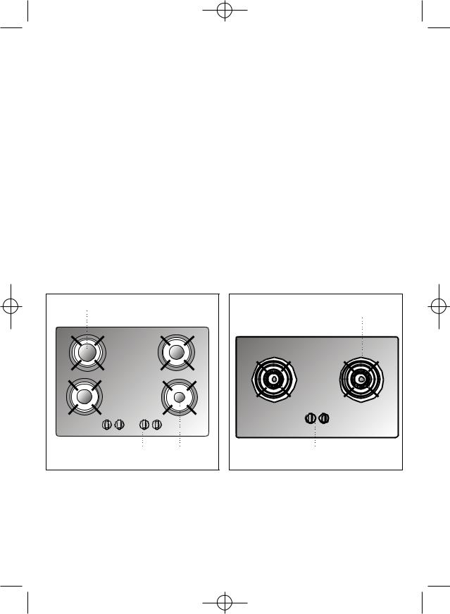
CG-Lux-70 4G, CG-Lux-70 4G AI AL |
CG-Lux-75 2G AI TR AL and CG Lux-75 2G AI TR |
|||||||
and CG Lux -70 4G AI (See drawing 7) |
(See drawing 8) |
|
|
|
|
|
||
1 |
Fast burner of 2,580 Kcal/h - 3 kW. |
1 |
Triple ring |
burner |
of |
3,010 |
Kcal/h |
- |
2 |
Semi fast burner of 1,500 Kcal/h - |
|
3.5 kW. |
|
|
|
|
|
|
1.75 kW. |
2 |
Triple ring |
burner |
of |
3,010 |
Kcal/h |
- |
3 |
Semi fast burner of 1,500 Kcal/h - |
|
3.5 kW. |
|
|
|
|
|
|
1.75 kW. |
3 |
Burner controls. |
|
|
|
|
|
4 |
Auxiliary burner of 860 Kcal/h - 1 kW. |
|
|
|
|
|
|
|
5 |
Burner controls. |
• All burners incorporate a pan support. |
|
|||||
|
|
• Maximum calorific power: 6,020 Kcal/h - |
||||||
• All burners incorporate a pan support. |
|
7 kW. |
|
|
|
|
|
|
•Maximum calorific power: 6,450 Kcal/h - 7.5 kW.
1 |
|
3 |
|
|
|
1 |
2 |
2 |
5 |
4 |
3 |
|
|
Drawing 7 |
Drawing 8 |
7
61401134/329 ingles 18/7/03 16:55 Página 8
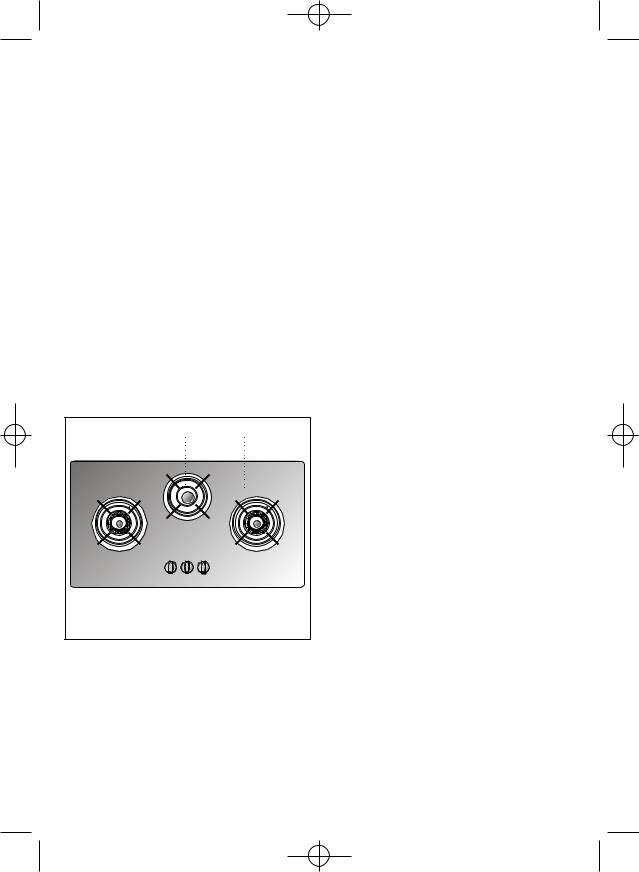
CG-Lux-86 3G AI TR AL and CG Lux-86 3G AI TR
(See drawing 9) |
|
|
|
|
|
|
1 |
Triple ring |
burner |
of |
3,010 |
Kcal/h |
- |
|
3.5 kW. |
|
|
|
|
|
2 |
Triple ring |
burner |
of |
3,010 |
Kcal/h |
- |
|
3.5 kW. |
|
|
|
|
|
3 |
Semi fast |
burner |
of |
1,500 |
Kcal/h |
- |
|
1.75 kW. |
|
|
|
|
|
4Burner controls.
•All burners incorporate a pan support.
•Maximum calorific power: 7,520 Kcal/h - 8.75 kW.
1 |
3 |
2 |
|
4 |
|
Drawing 9
8

61401134/329 ingles 18/7/03 16:55 Página 9
Installation
Important
INSTALLATION AND ADJUSTMENT MUST BE CARRIED OUT BY AUTHORISED TECHNICAL PERSONNEL ACCORDING TO THE APPLICABLE INSTALLATION REGULATIONS.
Positioning of the hobs
Depending on the model to be installed an aperture will be made in the worktop, of the dimensions specified in the drawing 10. A template is included in the packaging of models CG.1 4G. and CG.1 3G. 1P. for the correct sizing of the aper ture for these two hob models.
Warning: If the hob is assembled on any part of the furniture (drawers, cupboards, etc.) an intermediate separation must be placed between both at a minimum distance of 100 mm. from the lower part of the plate to avoid any involuntary direct contact. This intermediate separation must be permanent and only removed with tools.
For hobs with controls, its location must include a ventilation slot at the front, of 110 cm2. In this case the minimum distance between the lower part of the hob and the upper part of the furniture below the hob will be 20 mm. If there is no front ventilation slot, the minimum distance between the hob and the upper part of the furniture must be 130 mm.
The minimum vertical distance of the lower part of the piece of furniture placed above the hob will be 600 mm.
The piece of furniture where the hob with oven is to be placed will be properly fixed.
*In the case of the granite hob the measurement can be 580 mm.
Drawing 10
AMod.: CG Lux-60 y CGC 4G
BMod.: CG.1 3G. 1P. y CG.1 4G.
CMod.: CG Lux-70
DMod.: CG Lux-75
EMod.: CG Lux-86
9
61401134/329 ingles 18/7/03 16:55 Página 10
Positioning of the oven
See th applicable manual.
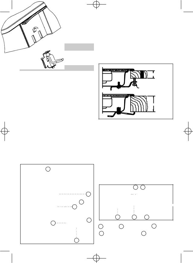
In the cases of the models CG.1 4G and CG.1 3G 1P, the clamps must be fitted as shown in the picture 12 depending on the thickness of the furniture.
Anchoring of the hob
Once the hob position has been dimensioned, the seal (J) must be affixed to the lower part of the cooker. This is fastened by means of four clamps (G), each of which has two tabs
(P) which are inserted in the apertures (O) in the hob until they click into place. To secure the clamp, open the tab (S) outwards a little as indicated in the figure. Once the seal and the clamps have been positioned the appliance may be installed in its position.
20/30 mm.
Self-tapping screw for worktops of 20 and 30 mm. wide
40mm. |
Drawing 12 |
Use a screwdriver to tighten the screws (T) on the four clamps and the hob will be perfectly secured in place. (See drawing 11).
N.B. It is imperative to install the seal under the brim of the worktop. Failure to install this may cause the worktop to be exposed to high temperatures.
J
S
|
O |
|
O |
|
G |
|
P |
Drawing 11 |
|
|
T |
10
For worktops 30 mm thick or less, use the M5 screws supplied as complementary fixation by introducing them into the circular hole of the clamp. A fillet shall form in this hole as the screw is introduced in it. This operation should be done before fastening the clamps to the hob.
To install hob model CGC 4G AI AL, insert the quick-fix nuts in the screw housings (see drawing 13), connect the clip which corres ponds with the height measurement of the hob unit (20, 30 and 40 mm) and tighten the screws until they are well secure.
|
|
A |
B |
|
|
|
|
|
20 mm. |
|
|
|
|
30 mm. |
|
|
|
|
40 mm. |
|
C |
D |
E |
|
|
|
|
|
Drawing 13 |
A |
Seal |
B Work top |
|
C Screw |
D |
Fastening clip |
E Quick-fix nut |
||
61401134/329 ingles 18/7/03 16:55 Página 11
Hob models CG-Lux-75 2G and CG-Lux-86 3G are installed in the same way as the CGC 4G AI AL, except for the staples which are geometrically different. The installation of these hobs must be carried out in the way shown in the drawing 14, depending on the thickness of the work top.
A B
20 mm.
30 mm.
40 mm.
|
|
|
|
D |
E |
Drawing 14 |
|
C |
|
|
|
|
Seal |
|
Work top |
|
C Screw |
A |
|
B |
|
|
|
D Fastening clip |
E |
Quick-fix nut |
|||
CGC 4G
Once the hob position has been dimensioned, the seal must be affixed (J) to the hob.
Fix the clamps (K) into the holes on the lower part of the case, as shown in drawing, by tightening the four screws supplied (ø4.2 mm).
The clamps (K) and seal (J) are supplied in the packaging along with the hob. (See drawing 15).
J
20
K |
J |
30 |
K |
J |
40 |
|
Drawing 15 |
K |
If the unit below the hob is to be used to store products it must be situated at a distance of at least 10 cm below the hob. Furthermore, it must be taken into account that the temperature in the interior of the furniture may rise to 60oC.
CONNECTING THE HOB TO THE OVEN
(Mod. CG.1 4G, CG.1 3G 1P and CGC 4G) OR THE CONTROL PANEL
To connect the hob to the oven, four telescopic universal joints are provided. (See drawing 16).
To make this connection, proceed as follows:
1Disconnect from the mains supply (mod. CG.1 3G 1P and CGC 4G AI AL).
2Detach the telescopic universal joints by pressing the retention tab (marked PUSH) using a thin screwdriver and extract the extender a few centimetres.
A
A
|
Drawing 16 |
B |
|
11
 Loading...