

Page 1

ST.TM.E10033.3
Issue 3
ENGLISH (UK)
INSTRUCTION MANUAL
E5500 Mobile Contribution Encoder
Software Version 2.8 (and later)
[Host Processor of Motherboard]
M2/ENC/E5500 and Options
Page 2

Preliminary Pages
f
ENGLISH ( K)
READ THIS FIRST !
If you do not understand the contents of this ma nu al
DO NOT OPERATE THIS EQUIPMENT.
Also, translation into any EC official language of this manual can be made
available, at your cost.
SVENSKA
LÄS DETTA FÖRST!
Om Ni inte förstår informationen i denna handbok
ARBETA DÅ INTE MED DENNA UTRUSTNING.
En översättning till detta språk av denna handbok kan också anskaffas, på
Er bekostnad.
PORTUGUÊS
LEIA O TEXTO ABAIXO ANTES DE MAIS NADA!
Se não compreende o texto deste manual
NÃO UTILIZE O EQUIPAMENTO.
O utilizador poderá também obter uma tradução do manual para o
português à própria custa.
FRANÇAIS
AVANT TOUT, LISEZ CE QUI SUIT!
Si vous ne comprenez pas les instructions contenues dans ce manuel
NE FAITES PAS FONCTIONNER CET APPAREIL.
En outre, nous pouvons vous proposer, à vos frais, une version française
de ce manuel.
ITALIANO
LEGGERE QUEST O AVVISO PER PRIMO!
Se non si capisce il contenuto del presente manuale
NON UTILIZZARE L’APPARECCHIATURA.
È anche disponibile la versione italiana di questo manuale, ma il costo è a
carico dell’utente.
NEDERLANDS
LEES DIT EERST!
Als u de inhoud van deze handleiding niet begrijpt
STEL DEZE APPARATUUR DAN NIET IN WERKING.
U kunt tevens, op eigen kosten, een vertaling van deze handleiding
krijgen.
SUOMI
LUE ENNEN KÄYTTÖÄ!
Jos et ymmärrä käsikirjan sisältöä
ÄLÄ KÄYTÄ LAITETTA.
Käsikirja voidaan myös suomentaa asiakkaan kustannuksella.
DANSK
LÆS DETTE FØRST!
MEDMINDRE DE TIL FULDE FORSTÅR INDHOLDET AF DENNE
Vi kan også for Deres regning levere en dansk oversættelse af denne
Udstyret må ikke betjenes
HÅNDBOG.
håndbog.
DEUTSCH
LESEN SIE ZUERST DIESEN HINWEIS!
Sollte Ihnen der Inhalf dieses Handbuches nicht klar verständlich sein,
BEDIENEN SIE DIESE GERÄTE NICHT!
Eine Übersetzung des Handbuches in diese Sprache ist gegen
dann
Berechnung lieferbar.
ESPAÑOL
LEA ESTE AVISO PRIMER O!
Si no entiende el contenido de este manual
NO OPERE ESTE EQUIPO.
Podemos asimismo suministrarle una traducción de este manual al
(idioma) previo pago de una cantidad adicional que deberá abonar usted
mismo.
This document and the information c ontained in it is the property o
TANDBERG Television Ltd and may be the subject of patents
pending and granted. It must not be used fo r commercial purposes
nor copied, disclosed, reproduced, stored in a retrieval system or
transmitted in any form or by any mea ns (electronic, mechanical,
photocopying, recording or otherwise), wheth er in whole or in part,
without TANDBERG Television’s prior written agreement.
2001 TANDBERG Television Ltd. All rights reserved.
ΕΛΛΗΝΙΚΑ
ÄΙΑΒΑΣΤΕ ΠΡÙΤΑ ΑΥΤΟ!
Αν δεν καταλÜβετε το περιεχüìενο αυτοý του βοηθÞìατοò/εγχειριδßου
ΜΗΝ ΛΕΙΤΟΥΡΓΗΣΕΤΕ ΑΥΤΟΝ ΤΟΝ ΕΞΟΠΛΙΣΜΟ.
Επßσηò, αυτü το εγχειρßδιο εßναι διαθÝσιìο σε ìετÜφραση
σε αυτÞ τη γλþσσα και ìπορεßτε να το αγορÜσετε.
Issue 3 first published in 2001 by:
ANDBERG TELEVISION LTD
T
REGISTERED ADDRESS:
ASINGHALL STREET
35 B
LONDON
EC2V 5DB
NITED KINGDOM
U
Registered Company Number 03695535
Page ii Instruction Manual: evolution 5000 E5500 Mob ile Co ntribution Encoder
ST.TM.E10033.3
Page 3

List of Contents
Chapter 1: Introduction
Gives a general description of the equipment and its main features and
functions. Identifies the controls, indicators and connectors on the front
and rear panels, and lists the available options.
Chapter 2: Installing the Equipment
Provides a guide to the suitability of an installation and gives detailed
procedures for the preparation and installation of the equipment. Also
details the external connectors and provides important safety
information.
Chapter 3: Operating the Equipment Locally
Describes local control in detail. Provides the power-up/-down procedures
and other general operating/control/set-up procedures.
Chapter 4: Equipment Description
Provides a high-level functional description of the eq ui p m ent and a brief
explanation of some of the principles used to ai d in understanding i ts
operation.
Preliminary Pages
Chapter 5: Preventive Maintenance and Fault-finding
Details routine maintenance tasks to be performed by the operator and
provides general servicing advice and fault-finding information. Provides
information regarding warranty and maintenance available from Customer
Services. Gives relevant disposal information.
Annex A: Glossary
Annex B: Technical Specification
Annex C: Error Messages
Annex D: Predefined User Configurations
Annex E: Language Abbreviations
Annex F: Creating and Downloading a Logo
Annex G: Quick Reference Guide
Index
Instruction Manual: evo lution 5000 E5500 Mobile Contribution Encode r Page iii
ST.TM.E10033.3
Page 4

Preliminary Pages
About this Manual
This manual provides instructions and information for the installation and
operation of the MCE.
This manual should be kept in a safe place for reference for the life of the
equipment. It is not intended that this manual will be amended by the
issue of individual pages. Any revision will be by a complete reissue.
Further copies of this manual can be ordered from the address shown on
page vi. If passing the equipment to a third party, also pass on the
relevant documentation.
Issues of this manual are listed below:
Issue Date Software Version Comments
1 May 2000 2.8 to 3.1 Initial release. Software version is that of the Host
1r1 July 2000 2.8 to 3.1 Contact information updated, minor formatting changes.
2 Aug 2000 2.8 to 3.1 Updated to include Remultiplexing, RAS and additional
3 Feb 2001 2.8 to 3.3 New functionality added: BISS; Linear audio PCM
Processor.
Audio options.
coding now compliant with SMPTE 302M; Auto lip sync
option; allow PIDs to be set via front panel; add Ident
text onto test patterns; include display/contrast setting;
include two ISOG configs; Brown out feature added
(QPSK Modulator); add Power On State (Modulator
menu). Manual reformatted to corporate style.
The following associated manuals are also av ailable:
• ST.TS.E9140: Remote Control Protocol
• ST.TS.SNMP.E10022: SNMP Remote Control Protocol.
Acknowledgements
General
All best endeavours have been made to acknowledge registered
trademarks and trademarks used throughout this manual. Any notified
omissions will be rectified in the next issue of this manual. Some
trademarks may be registered in some countries but not in others.
Registered trademarks and trademarks used are acknowledged below and
marked with their respective symbols. However, they are not marked
within the text of this manual.
Registered Trademarks
AC-3® is a registered trademark of Dolby Laboratories Licensing
Corporation.
Dolby Digital® is a registered trademark of Dolby Laboratories Licensing
Corporation.
Page iv Instruction Manual: evo lution 5000 E5500 Mobile Contribution Encoder
ST.TM.E10033.3
Page 5

Musicam® is a registered trademark of Thomson and Télédiffusion de
France (TDF), Europe, and is a registered trademark of CCS (now Musicam
USA Incorporated), USA.
Pro Logic® is a registered trademark of Dolby Laboratories Licensing
Corporation.
Ethernet® is a registered trademark of Xerox Corporation.
XILINX® is a registered trademark of Xilinx Inc.
Trademarks
NDS™ is a trademark of NDS Limited.
Pozidriv™ is a trademark of European Industrial Services.
Panasonic™ is a trademark of Matsushita Electric.
Warnings, Cautions and Notes
Heed Warnings
Preliminary Pages
All warnings on the product and in the operating instructions should be
adhered to. The manufacturer can not be held responsible for injuries or
damage where warnings and cautions have been ignored or taken lightly.
Read Instructions
All the safety and operating instructions should be read before this product
is operated.
Follow Instructions
All operating and user instructions should be followed.
Retain Instructions
The safety and operating instructions should be retained for future
reference.
WARNINGS GIVE INFORMATION WHICH, IF STRICTLY OBSERVED, WILL PREVENT PERSONAL
INJURY OR DEATH, OR DAMAGE TO PERSONAL PROPERTY OR THE ENVIRONMENT. THEY
ARE BOXED AND SHADED FOR EMPHASIS, AS IN THIS EXAMPLE, AND ARE PLACED
IMMEDIATELY PRECEDING THE POINT AT WHICH THE READER REQUIRES THEM.
WARNINGS....
CAUTIONS...
Cautions give information which, if strictly followed, will prevent damage to equipment or other goods.
They are boxed for emphasis, as in this example, and are placed immediately preceding the point at
which the reader requires them.
NOTES...
Notes provide supplementary information. They are highlighted for emphasis, as in this example, and
are placed immediately after the relevant text.
Instruction Manual: evo lution 5000 E5500 Mobile Contribution Encode r Page v
ST.TM.E10033.3
Page 6

Preliminary Pages
EMC Compliance
This equipment is certified to the EMC requirements detailed in Annex B,
Technical Specifications. To maintain this certification, only use the leads
supplied or if in doubt contact Customer Services.
Contact Information
TANDBERG Television Customer Services
Support Services
Our primary objective is to provide first class customer care that is tailored
to your specific business and operational requirements. All levels are
supported by one or more service performance reviews to ensure the
perfect partnership between TANDBERG Television and your business.
Levels of Support
We offer a number of support service levels so you can choose the one
most appropriate to your business requirements.
• For the initial 12 months, Bronze Level Support is provided free on
this product. An extended time period can be purchased for this level.
• Silver Level Support extends the coverage to include on-site support,
preventive maintenance and discount on pre-designed training.
• The Gold Level Support gives an enhanced support package. It builds
on the Silver Level by including advanced repair exchange, an account
focused engineer, version migration support and further discount on
predesigned training.
Where to Find Us
Europe, Middle East +44 (0) 23 8048 4455
and Africa: Fax: +44 (0) 23 8048 4467
Americas Office: + 1 888 637 0023
South Americas Office: + 1 949 725 2699
Hong Kong Office: + 852 2899 7000
Australia/NZ Office: +61 2 9356 8599
Internet Address: http://www.tandbergtv.com
fieldservice@tandbergtv.com
fieldservice-americas@tandbergtv.com
fieldservice-americas@tandbergtv.com
fieldservice-asia@tandbergtv.com
fieldservice-australia@tandbergtv.com
Page vi Instruction Manual: evolution 5000 E5500 Mobile Co ntr ibution Encoder
ST.TM.E10033.3
Page 7

Preliminary Pages
Technical Training
Training Courses
TANDBERG Television provides a wide range of training courses on the
operation and maintenance of our products and on their supporting
technologies. TANDBERG can provide both regularly schedul ed courses and
training tailored to individual needs. Courses can be run either at your
premises or at one of our dedicated training facilities.
Where to Find Us
For further information on TANDBERG Television's training programme
please contact us:
International Telephone: +44 23 8048 4229
International Facsimile +44 23 8048 4467
E-mail Address: training@tandbergtv.com
Internet Address http://www.tandbergtv.com
Customer Services and Technical Training Postal Address
Tandberg Television
Strategic Park
Comines Way
Hedge End
Southampton
Hampshire
SO30 4DA
United Kingdom
Technical Publications
If you need to contact TANDBERG Television Technical Publications
regarding this publication, e-mail: techpubs@tandbergtv.com.
Instruction Manual: evo lution 5000 E5500 Mobile Contribution Encode r Page vii
ST.TM.E10033.3
Page 8

Preliminary Pages
BLANK
Page viii Instruction Manual: evo lution 5000 E5500 Mobile Contribution Encoder
ST.TM.E10033.3
Page 9

Contents
1.1 Scope of this Manual.................................................1-3
1.1.1 Who Should Use this Manual........................1-3
1.1.2 Software Versions.........................................1-3
1.1.3 Equipment Covered by this Manual..............1-3
Equipment Model..........................................1-3
Information Label..........................................1-4
Hardware Configuration................................1-5
Build Revision...............................................1-5
Firmware / Software Versions.......................1-5
1.2 Role of the MCE........................................................1-5
1.2.1 Typical System..............................................1-5
1.3 Summary of Features................................................1-7
1.3.1 Video Encoding.............................................1-7
MPEG-2 Encoding........................................1-7
Video Encoding Modes.................................1-7
Video Input Types.........................................1-8
Serial Digital Video Input Error Detection
and Handling (EDH)......................................1-8
Video Encoding Functions............................1-8
Motion Estimation..........................................1-8
Video Variable Bit-rate..................................1-9
Coding Resolutions.......................................1-9
Internal Frame Synchroniser.........................1-9
Output on Video Loss....................................1-9
1.3.2 Audio Encoding.............................................1-9
General.........................................................1-9
Audio Inputs................................................1-10
Audio Channels...........................................1-10
MPEG Encoding Modes..............................1-10
Audio Variable Bit-rate................................1-11
Dolby Digital (AC-3)....................................1-12
Chapter 1
1. Introduction
Pre-encoded AC-3......................................1-12
Test Tone ...................................................1-12
1.3.3 Vertical Blanking Interval Line Processing..1-12
Vertical Blanking Interval Line Processing
Modes.........................................................1-12
1.3.4 Data Channels............................................1-14
1.3.5 QPSK IF Modulation...................................1-14
1.3.6 Control and Monitoring...............................1-14
Methods......................................................1-14
1.4 Guided Tour............................................................ 1-15
1.4.1 The User Interface......................................1-15
1.4.2 LED Colour Coding Philosophy..................1-15
1.4.3 Front Panel Description..............................1-15
Components...............................................1-15
Front Panel Status Display and Keyboard..1-15
1.4.4 Rear Panel Description...............................1-16
1.4.5 Construction................................................1-17
Enclosure....................................................1-17
Boards/Modules in the MCE.......................1-17
1.5 Standard Modules...................................................1-18
1.5.1 Functions....................................................1-18
1.5.2 Analogue Video Input (M2/EOM1/VID).......1-18
1.5.3 Frequency Agile QPSK Modulator
(M2/EOM1/QPSK2)....................................1-18
1.5.4 RS-232 and RS-422 Data Input
(M2/EOM1/DAT).........................................1-18
1.6 Option Modules.......................................................1-19
1.6.1 Module Numbering.....................................1-19
1.6.2 RAS Scrambling Module
(M2/EOM1/RAS).........................................1-19
1.6.3 Internal Remux module
(M2/EOM1/REMUX)...................................1-20
Instruction Manual: evolution 5000 E5500 Mobile Contribution Encoder Page 1-1
ST.TM.E10033.3
Page 10

Introduction
List of Illustrations
Figure 1.1: Mobile Contribution Encoder Front View.....................1-3
Figure 1.2: Information Label 1......................................................1-4
Figure 1.3: Information Label 2......................................................1-4
Figure 1.4: Correlation Between Hardware and Build Standard
Numbers.......................................................................1-4
Figure 1.5: Typical evolution 5000 MCE Configuration.................1-6
Figure 1.6: Typical Remultiplexing Configuration (Remux
Option Fitted)................................................................1-7
Figure 1.7: Front Panel Indicators................................................1-16
Figure 1.8: Rear Panel Connectors .............................................1-16
List of Tables
Table 1.1: Equipment Model Description.......................................1-4
Table 1.2: Video Coding Resolutions and Typical Bit-rates...........1-9
Table 1.3: MPEG-2 Audio Encoding Bit-rates..............................1-11
Table 1.4: Dolby Digital Audio Encoding Bit-rates.......................1-12
Table 1.5: Front Panel Indicators.................................................1-15
Table 1.6: Mandatory Card and Module Positions.......................1-17
Table 1.7: RAS and REMUX Module Numbering........................1-19
Page 1-2 Instruction Manual: evolution 5000 E5500 Mobile Contribution Encoder
ST.TM.E10033.3
Page 11

1.1 Scope of this Manual
1.1.1 Who Should Use this Manual
This manual is written for operators/users of the E5500 Mobile
Contribution Encoder (MCE). The Mobile Contribution Encoder is used as a
stand-alone unit to output a complete modulated transport stream into a
satellite network.
The manual is written to assist in the installation, operation and day-to-day
care of the unit. All information is applicable to all models of the Encoder
unless otherwise stated.
WARNING…
DO NOT REMOVE THE COVERS OF THIS EQUIPMENT. HAZARDOUS VOLTAGES ARE PRESENT
WITHIN THIS EQUIPMENT AND MAY BE EXPOSED IF THE COVERS ARE REMOVED. ONLY
TANDBERG TELEVISION TRAINED AND APPROVED SERVICE ENGINEERS ARE PERMITTED TO
SERVICE THIS EQUIPMENT.
CAUTION…
Unauthorised maintenance or the use of non-approved replacements may affect the equipment
specification and invalidate any warranties.
Introduction
This manual does not include any maintenance information or procedures
that require the removal of covers.
1.1.2 Software Versions
This manual has been written to cover the functionali ty of firmware version
1.1 and later of the Motherboard
later of the Host Processor of the Motherboard. The current software
version can be found by viewing the Version Info Menu (see Chapter 3,
Figure 3.9).
This manual continues to be relevant to subsequent firmware issues where
the functionality of the equipment has not changed. Where a new issue of
firmware changes the functionality, a new issue of this manual is provided.
1
(S8475) and software version 2.8 and
1.1.3 Equipment Covered by this Manual
Equipment Model
Figure 1.1: Mobile Contribution Encoder Front View
The MCE comprises an enclosure with a Motherboard
1
and Video
Compression Module fitted. The three option slots of the bottom tray are
fitted with a Video Input Module, a Data Input Module and a QPSK
Modulator Card.
1
S8475 is sometimes referred to as the Base Board 3ASI.
Instruction Manual: evolution 5000 E5500 Mobile Contribution Encoder Page 1-3
ST.TM.E10033.3
Page 12
Introduction
p
If option slot 4 is not occupied by an option module, it must have a
blanking module fitted to maintai n correct internal air-flow (see Table 1.7).
The marketing product number and model number of the basic unit is
shown in Table 1.1.
Table 1.1: Equipment Model Description
Model
Name
Encoder E5500 E10033
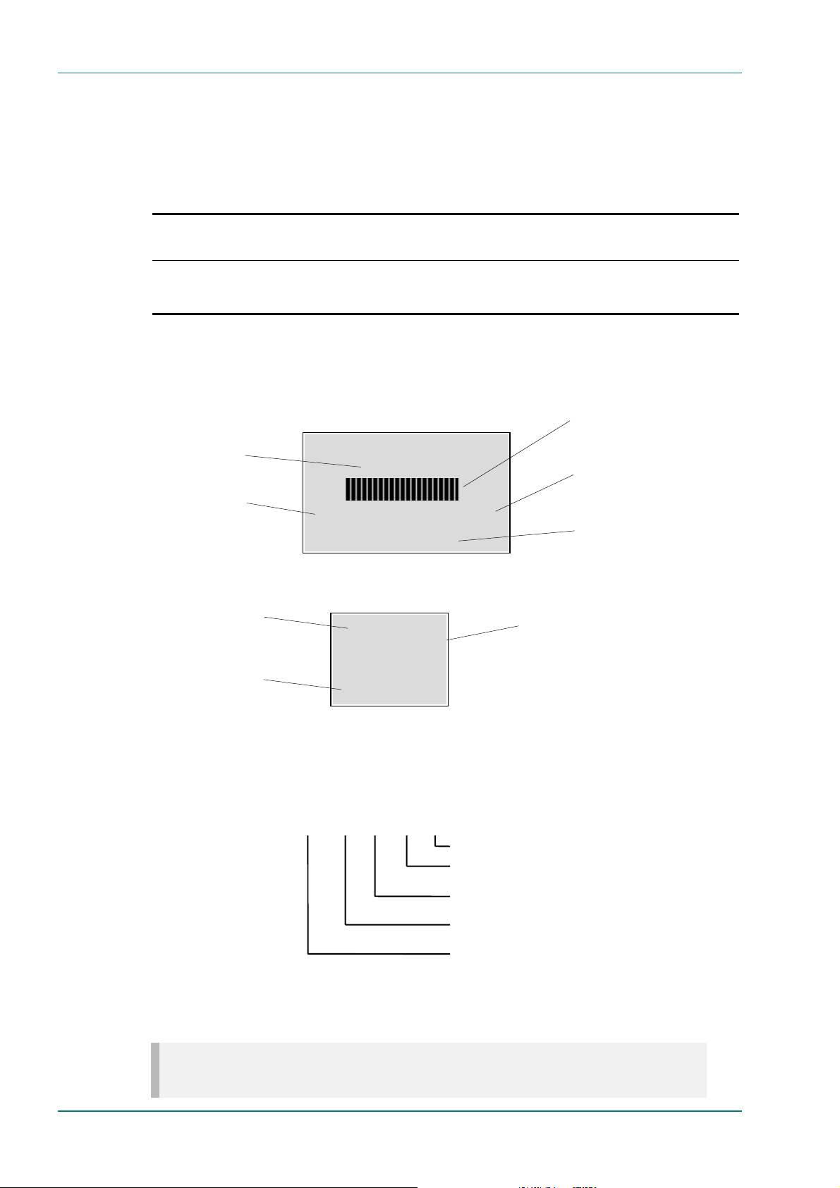
Information Label
There are two information labels which identify the configuration of the
unit. Figure 1.2 and Figure 1.3 are typical examples.
Serial Number
A unique number for unit identification
Hardware Configuration
A reference which identifies each
piece of hardware in the equipment
Figure 1.2: Information Label
Product Name
A name which identifies the type
roduct
of
Marketing Number
A code which identifies the product
for marketing purposes
Model
Number
Marketing
Description
Number
M2/ENC/E5500
MPEG-2 Encoder with 4:2:0 video encoding mode (4:2:2 is available
as a purchasable upgrade), analogue video, SDI and data inputs.
QPSK modulation.
EVOLUTION 5000 ENCODER
Serial No. 41
10033 – 49 Bld rev 1_0_3
M2/ENC/E5500
ENCODER
Serial No. NNNN
10033 – 49
Bld rev 1_0_3
M2/ENC/E5500
Bar Code
Used for unit identification in the
manufacturing process
Build Revision
A reference which identifies the build
revision of the equipment
Marketing Number
A code which identifies the product
for marketing purposes
Serial Number
A unique number for unit identification
Figure 1.3: Information Label 2
Option Slot Number
Hardware Configuration
Build Standard
n/a 1234For reference – not shown on label (see Figure 1.7).
10033 -1 -3 -2 -49 Each piece of hardware has a unique number (see Table 1.7).
01 -01 -01 -01 -01
Refers to a Blank Module in option slot 4.
Refers to a QPSK Module in option slot 3.
Refers to a Non DVB Data IP Module (sometimes known as
an RS-422 Data Input Module) in option slot 2.
Refers to a Video Input Module in option slot 1.
Refers to the basic enclosure with one Motherboard (Base
Board 3ASI) and one Video Compression Module fitted.
Figure 1.4: Correlation Between Hardware and Build Standard Numbers
NOTE…
Refer to Table 1.7 and Figure 1.8 for the position of the module slots.
Page 1-4 Instruction Manual: evolution 5000 E5500 Mobile Contribution Encoder
ST.TM.E10033.3
Page 13

Introduction
Hardware Configuration
Each piece of hardware has a specific reference number. These are linked
to give a hardware configuration number (see Figure 1.4) for the whole
unit. The first part of the number refers to the enclosure and any
mandatory modules, and each subsequent part refers to an option module.
Refer to Table 1.7 for the positions of each option module.
Build Revision
The build revision number (see Figure 1.4) refers to the physical status of
the enclosure and any option modules at the time the equipment was
shipped from the factory.
Firmware / Software Versions
This manual has been written to cover the functionali ty of the firmware
versions which are contained within the bui ld standard identified on the
information label (see the rear of the Encoder and also Figure 1.4).
This manual continues to be relevant to subsequent build standards where
the functionality of the equipment has not changed. Where the build
standard changes the functionality, a new issue of this manual is provided.
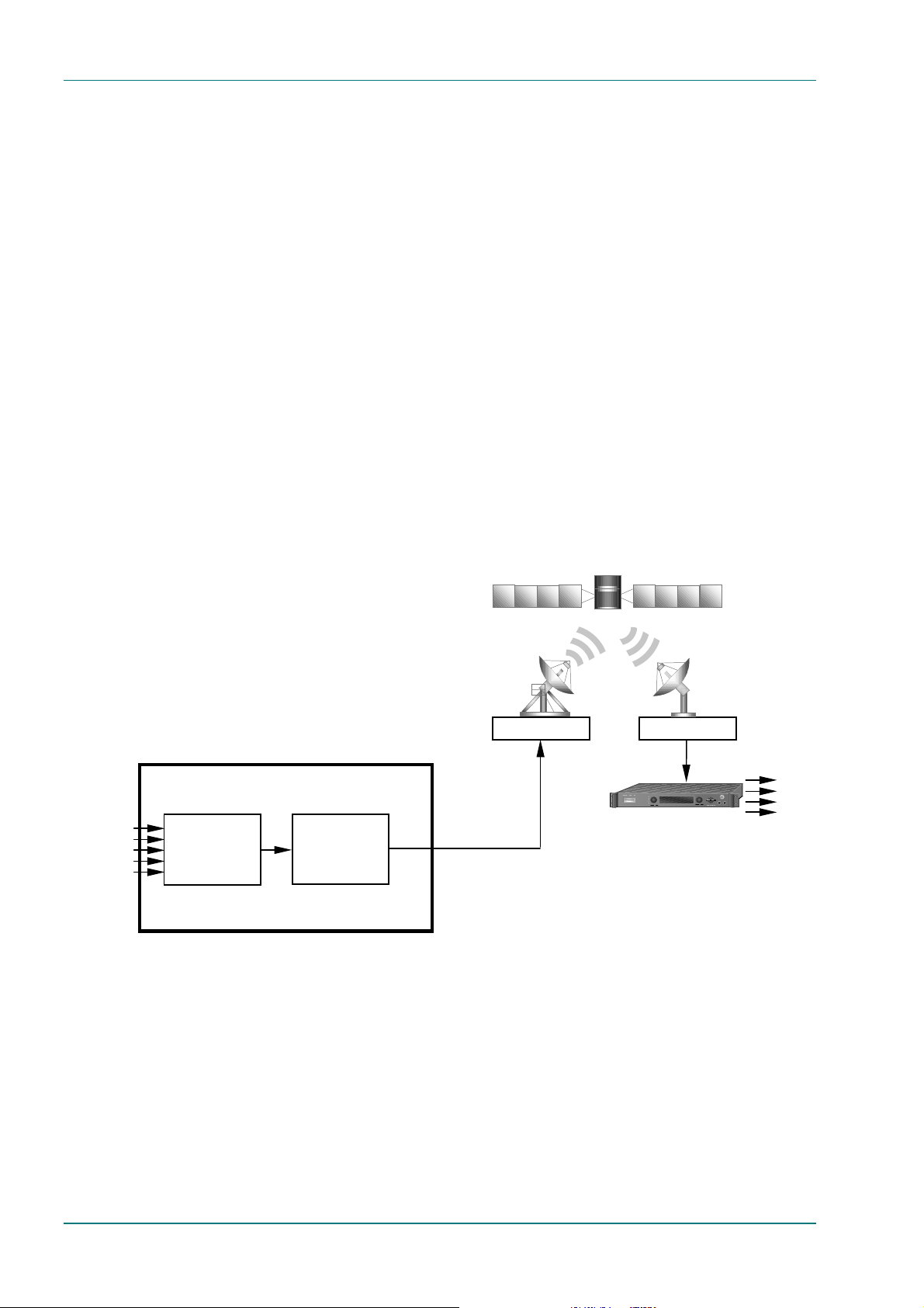
1.2 Role of the MCE
1.2.1 Typical System
The Mobile Contribution Encoder (MCE) is a transportable digital exciter
designed specifically for mobile contribution applications. It is compact and
lightweight, fully MPEG-2 and DVB compl iant, and has high performance
for the transmission of studio-quality video material. The equipment is
designed to be suitable for both flyaway use (within an appropriate flight
case) and truck installation.
The Encoder comprises a single vi deo encoder, two stereo audio encoders
(dual standard MPEG-1 (layer 2)/Dolby Digital) and general purpose VBI
extraction and encoding circuitry.
High quality video encoding is ensured by the inclusion of di gital noise
reduction techniques and many other proprietary algorithms as well as
standard MPEG compression techniques. Hierarchical motion estimation is
also used.
Video is input to the unit in Composite, Component or serial digital (SDI)
format. There is also a logo overlay facility allowing broadcasters to
trademark material.
Transponder bandwidth can be traded with video quality by operating the
video compression bit-rate in the range 1.5 – 45 Mbit/s. Over this
operating range, encoded video resolution can be controlled in order to
optimise subjective encoding performa nce.
The MCE encodes up to four channels of audio, which may be configured
as four mono channels or two stereo pairs, input as either analogue or
AES/EBU digital audio.
Instruction Manual: evolution 5000 E5500 Mobile Contribution Encoder Page 1-5
ST.TM.E10033.3
Page 14
Introduction
One channel of asynchronous data and one channel of high speed
synchronous data can also be supported (data channels are not
compressed).
The MCE multiplexes these input signals, under user control, to provide
secure programme transmission. The digi tal stream is then processed for
forward error correction (FEC) and modulates a single IF carrier for output
to an Up-converter and High Power Amplifier (HPA) equipment for
transmission to the satellite.
If the Compact Remultiplexing option module is fitted, the MCE is capable
of accepting up to three separate transport streams via ASI connectors
and, (together with the host encoder transport stream), provides four
transport streams multiplexed together. Refer to Figure 1.6 and Chapter 4,
Equipment Description for details.
Local control of the equipment is via the front panel keypad and display.
The MCE can also be controlled remotely over an Ethernet interface or
RS-232/RS-485 port. Local health monitoring is incorporated, along with a
local alarm/fail/reset port.
The equipment is fully configurable and extremely flexible, while still being
simple to operate and maintain. Various alignment, testing and diagnostic
facilities have been incorporated to assist with operation and maintenance
in the field.
VIDEO (ANALOGUE)
VIDEO (DIGITAL)
AUDIO
SYNC DATA
ASYNC DATA
Up-link equipment
(including
Up-converter and
High Power
Amplifier)
E5500 Mobile Contribution Encoder
Encoder
Modulator
IF
Figure 1.5: Typical evolution 5000 MCE Configuration
Down-link equipment
(including Low
Noise Block)
Tx
BER STATUS
Alteia Satellite Receiver
LNB
VIDEO
MULTIFUNCTIONAL DISPLAY
ALTEIA
ALARM
REMOTE CNTRL
AUTHORIZED
LOCK
AUDIO
ASYNC DATA
SYNC DATA
Page 1-6 Instruction Manual: evolution 5000 E5500 Mobile Contribution Encoder
ST.TM.E10033.3
Page 15
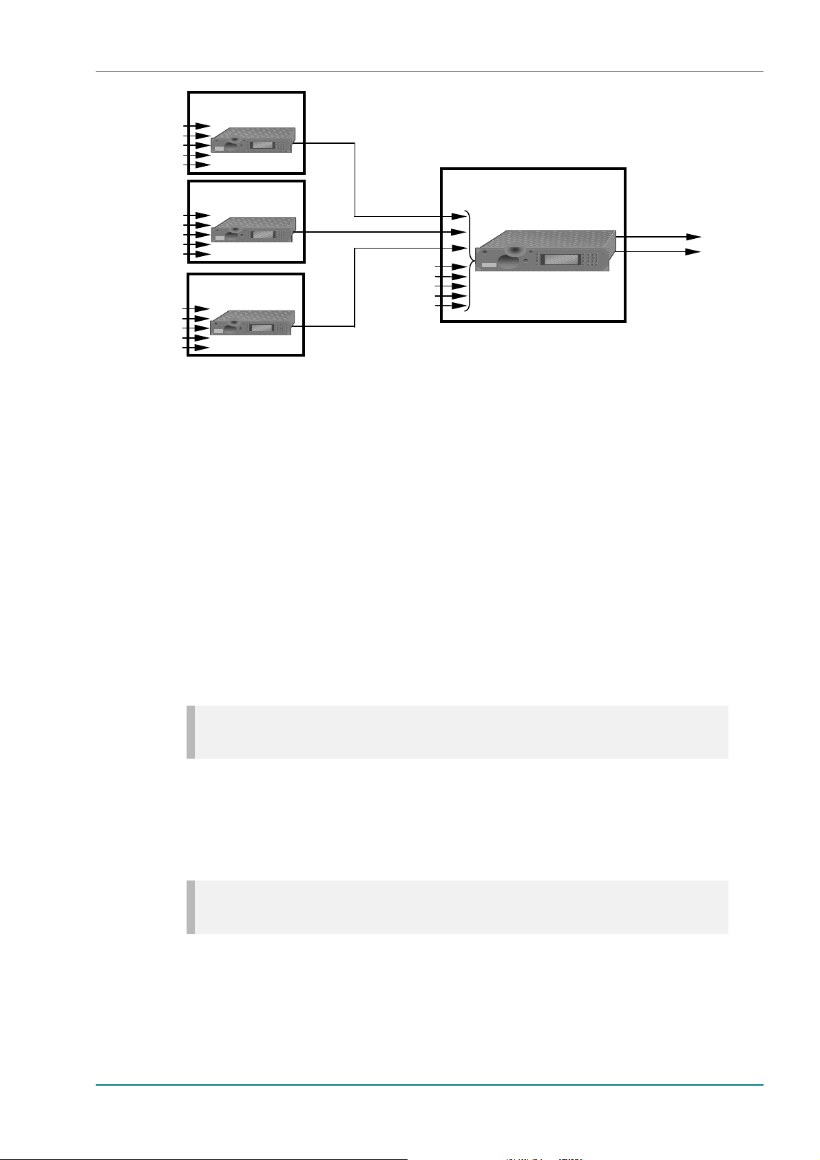
VIDEO (ANALOGUE)
VIDEO (DIGITAL)
AUDIO
SYNC DATA
ASYNC DATA
VIDEO (ANALOGUE)
VIDEO (DIGITAL)
AUDIO
SYNC DATA
ASYNC DATA
VIDEO (ANALOGUE)
VIDEO (DIGITAL)
AUDIO
SYNC DATA
ASYNC DATA
E5500 Mobile
Contribution Encoder 1
TANDBER
G
E5500 Mobile
Contribution Encoder 2
TANDBER
G
E5500 Mobile
Contribution Encoder 3
TANDBER
G
DVB ASI
(SERVICE 2)
1 2 3
4 5 6
7 8 9
E5500
Mobile Contribution
DVB ASI
(SERVICE 3)
1 2 3
4 5 6
7 8 9
VIDEO (ANALOGUE)
VIDEO (DIGITAL)
AUDIO
DVB ASI
(SERVICE 4)
1 2 3
4 5 6
7 8 9
SYNC DATA
ASYNC DATA
(Master) Encoder
TANDBERG
SERVICE 1
Figure 1.6: Typical Remultiplexing Configuration (Remux Option Fitted)
1 2 3
4 5 6
7 8 9
0 * ±
Introduction
DVB ASI OUT
IF (4 SERVICES)
1.3 Summary of Features
1.3.1 Video Encoding
MPEG-2 Encoding
The encoder processes a broadcast-standard video signal into a
compressed encoded bit-stream in accordance with:
• The MPEG-2 Main profile @ Main level (MP@ML) specification (ISO/IEC
13818); or
• The MPEG-2 4:2:2 Profile @ Main Level (4:2:2P@ML) specification
(ISO/IEC 13818).
NOTE…
The 4:2:2 option will only be available if purchased as an option.
Video Encoding Modes
Either the 4:2:0 or 4:2:2 video encoding modes can be selected. The
coding mode selected affects the compression techniques, encoder delay
and rate control.
NOTE…
The 4:2:2 option will only be available if purchased as an option.
Instruction Manual: evolution 5000 E5500 Mobile Contribution Encoder Page 1-7
ST.TM.E10033.3
Page 16

Introduction
Video Input Types
The video input types which are supported are:
• Analogue Composite – 625-line, PAL-B, -D, -G, -H or -I (ITU-R BT.
624-4).
• Analogue Composite – 525-line, NTSC-M (with or without pedestal)
(ITU-R BT. 624-4).
• Analogue Component –YP
5).
• Analogue Component – YP
pedestal), or 525 line (no pedestal, Beta levels) format (ITU-R BT.
601-5).
• Serial Digital (SDI) – 4:2:2 YC
serial format), SMPTE-259M.
, PAL 625 line format (ITU-R BT. 601-
RPB
, NTSC 525 line (with or without
RPB
(ITU-R BT. 656-1 part 3) (“D1”
RCB
• Internal test pattern function.
Serial Digital Video Input Error Detection and Handling (EDH)
The serial digital video input supports error detection and handling (EDH)
as defined by the specification SMPTE RP 165-1994, ‘Error Detection
Checkwords and Status Flags for Use in Bit Serial Digital Interfaces for
Television’. Refer to Chapter 4, Equipment Description for further
information.
Video Encoding Functions
The standard video encoding functions include:
• Support for all MP@ML standard coding modes, (and 422P@ML, if
purchased).
• Selectable bit-rate operation, 1.5 Mbit/s - 15 Mbit/s.
• Support for the standard set of video picture resolutions (720, 704,
640, 544, 480, 352 and SIF) in both 625 and 525 line operation.
• Hierarchical motion estimati on.
• A built in frame resynchroniser to maintain a valid encoded bit-stream
in the event of loss of vi d eo.
• Various low delay modes for delay critical applications.
• Support for a variety of Group of Pictures (GOP) structures with a
variable number of B frames.
• Built in patented adaptive noise reduction circuitry.
• The ability to generate internal video test patterns. These can be
moving, with the ability to load 2 frames.
• A logo overlay facility whereby the MCE is able to overlay broadcaster’s
logos onto the active video.
• Various video fail options, eg, freeze frame, cut to black.
Motion Estimation
The MCE uses Hierarchical motion estimati on. It takes a macro block (16
pixels x 16 pixels) and then performs a series of exhaustive searches for
that block on areas of increasing resolution homing in on an exact match.
Page 1-8 Instruction Manual: evolution 5000 E5500 Mobile Contribution Encoder
ST.TM.E10033.3
Page 17

Introduction
Video Variable Bit-rate
The MPEG-2 compression algorithm uses adaptive fiel d/frame coding,
forward and backward predictive processing with motion estimation and
compensation to reduce the bit-rate to the range 1.5 to 15 Mbit/s.
NOTE…
If the 4:2:2 upgrade has been purchased, video bit-rates of up to 50 Mbit/s are available on the ASI
output. The actual modulated output depends on the symbol rate (which has a maximum of 30
Msymbols/s).
Coding Resolutions
To provide optimum picture quality over the full bit-rate range, the
encoded picture resolution is controlled automatically according to the
video bit-rate. Alternatively, the user can override this and select manual
control, if desired. Avai lable coding resolutions are shown in Table 1.2.
Table 1.2: Video Coding Resolutions and Typical Bit-rates
625 Line Modes 525 Line Modes Typical Bit-rate
4:2:0 (Mbit/s)
720 pixels x 576 lines 720 pixels x 480 lines 4.0 – 8.0 up to 50.
704 pixels x 576 lines 704 pixels x 480 lines 4.0 – 8.0 up to 50.
544 pixels x 576 lines 544 pixels x 480 lines 2.5 – 6.0 480 pixels x 576 lines 480 pixels x 480 lines 2.0 – 6.0 352 pixels x 576 lines 352 pixels x 480 lines 1.5 – 4.0 -
Typical Bit-rate 4:2:2 (Mbit/s)
System configuration can be stored in non-volatile random access memory
(NVRAM) for restoration of configured state at power-on.
Internal Frame Synchroniser
An internal frame synchroniser is incorporated to maintain a valid encoded
bit-stream in the event of discrepancies between the relative timing of the
input video syncs and the internal flywheel syncs.
Output on Video Loss
The MCE can be software-configured to show, in the event of video input
loss, either:
• Test pattern
• Freeze frame
• Cut to a black screen.
1.3.2 Audio Encoding
General
Audio can be encoded to either:
• MPEG-1 Audio (layer 2) standard (sampling rate 32 kHz or 48 kHz).
• Dolby Digital (sampling rate 32 kHz, 44.1 kHz or 48 kHz).
Output bit-rate is selectable in the range 32-384 kbit/s (dependent on
configuration) for MPEG-1 Audio (layer 2) and 56-640 kbit/s
(dependent on configuration) for Dolby Digital.
Instruction Manual: evolution 5000 E5500 Mobile Contribution Encoder Page 1-9
ST.TM.E10033.3
Page 18

Introduction
• Pre-compressed (or pre-encoded – IEC 61937) audio in pass-through
mode is also available (i t only operates at 48 kHz). This is where an
audio stream has already been encoded externally, pri or to entering
the Encoder, and passes through to the output. This type of audio is
supported in Dolby Digital.
NOTE…
Motherboard software prior to ver 3.3 included Dolby Digital (AC-3) as part of the standard product.
A separate licence is required from software ver 3.3, this is available from TANDBERG Television.
The input for this type of audio is either vi a the Serial Digital Input of
the audio connector or it can be embedded with the incoming video.
Audio Inputs
The standard audio input is:
• AUDIO IN - 15 way male D-type - software selectable balanced
analogue or digital AES/EBU, with AES/EBU on left only. The right
channel can be configured to output a reference AES/EBU signal for an
external Dolby AC-3 Encoder. The audio connector is a 15-way male Dtype, but a break out cable is supplied which plugs into this connector
and provides a more convenient means of connecting the audio inputs
via four XLR female connectors.
• Alternatively, audio can be input embedded as AES/EBU on the serial
digital input (SDI). In this mode a maximum of four stereo pairs can
be extracted. Audio may be converted to either of the standard output
frequencies, 32 kHz or 48 kHz, by use of the built-in asynchronous
sample rate converters.
Audio Channels
The MCE supports four channels of audio, which may be configured as:
• Four analogue single mono channels, 600 Ω or 20 kΩ
• Two analogue stereo pairs, 600 Ω or 20 kΩ
• Two digital channels, AES/EBU or embedded SDI.
MPEG Encoding Modes
The two stereo pairs may be config ured in various MPEG-2 encoding
modes:
• Single mono: a mono si gnal is encoded on the left channel only
• Dual mono: the left and right signals are encoded and carried in the
transport stream as a single Packetised Elementary Stream (PES) data
stream. The way that the left and right signals are output from the
receiver is dependent on how the routing is set up on the receiver.
Both the left and the right may be output, or the left only, or the right
only. This is typically used for multilingual services
• Stereo: A stereo pair is coded as two mono signals - the two signals
are output as stereo at the receiving end
• Joint/intensity stereo: A stereo pair is coded taking advantage of
the stereo nature of the channels - the two signals are output as
stereo at the receiving end.
Page 1-10 Instruction Manual: evolution 5000 E5500 Mobile Contribution Encoder
ST.TM.E10033.3
Page 19

Introduction
NOTE…
Joint/intensity stereo is not available in Dolby Digital mode.
Audio Variable Bit-rate
MPEG-1 audio output bit-rate (see Table 1.3) is selectable in the range
32-384 kbit/s (dependent on configuration).
Table 1.3: MPEG-2 Audio Encoding Bit-rates
Bit-rate
(kbit/s)
32 - - 48 - - 56 - - 64
80 - - 96
112
128
160
192
224 256 320 384 -
Single
Channel
Mono
Dual
Channel
Mono
Dual
Channel
Stereo
Dual Channel
Joint (Intensity)
Stereo
Instruction Manual: evolution 5000 E5500 Mobile Contribution Encoder Page 1-11
ST.TM.E10033.3
Page 20

Introduction
Dolby Digital (AC-3)
Dolby Digital (AC-3) audio encoding incorporates digital normalisation,
preprocessing (filtering), dynamic range compression and the addition of
bit-stream information. Dolby Pro Logic audio can be carried as stereo
audio through the Encoder as long as a suitably high bit-rate is selected.
The audio outputs may be configured in single channel mono (1/0) or dual
channel stereo (2/0) encoding mode. The audio output bit-rate is
selectable in the range 56 – 640 kbit/s (dependent on configuration). See
Table 1.4.
Table 1.4: Dolby Digital (AC-3) Audio Encoding Bit-rates
Bit-rate
(kbit/s)
56 64 80 96
112
128
160
192
224
256
320
384
448
512
576
640
Single Channel
Mono (1/0)
Dual Channel
Stereo (2/0)
Pre-encoded AC-3
The encoder supports pre-encoded AC-3 to the standard IEC 61937,
‘Interfaces for Non-linear PCM Encoded Audio Bitstreams applying
IEC 60958’.
Test Tone
The equipment can be configured to generate a test tone for alignment
purposes. Refer to Annex B, Technical Specification for level and
frequency.
1.3.3 Vertical Blanking Interval Line Processing
Vertical Blanking Interval Line Processing Modes
Introduction
The Encoder has three possible modes for processing Vertical Blanking
Interval (VBI) lines.
Page 1-12 Instruction Manual: evolution 5000 E5500 Mobile Contribution Encoder
ST.TM.E10033.3
Page 21

Introduction
NOTE…
The following three processing modes are only available if the 4:2:2 upgrade is purchased.
VBI in Picture
By selecting the extended activ e picture format available in the MPEG
4:2:2 specification the MCE compresses and transmits the VBI data as part
of the active picture. This mode requires up to 3 Mbit/s of extra bit-rate,
depending on the amount and complexity of the VBI present.
NOTE…
VBI in Picture transmits the VBI waveform as part of the picture and as such will be subject to some
distortion. Most analogue VBI types are robust against this type of distortion but others, e.g. video
index, are intended for SDI transmission and will not survive MPEG coding/decoding in VBI in Picture
mode.
VBI in PID
The MCE has the ability to extract and transmit a wide variety of VBI line
formats. Field Programmable Gate Array (FPGA) circuitry on the front end
of the equipment incorporates a number of general purpose li ne grabbers
so that known formats of VBI data can be extracted. Closed caption data
together with other formats of VBI data such as VITC and VPS are to be
transmitted in the user data field of the video.
The following VBI data formats are supported:
• Line 21 data Services EIA-608 (Closed Caption and V-chip)
• Neilson AMOL 11
• VITC (EBU and SMPTE)
• Programme Delivery and Control PDC, via ITU-R system B Teletext
extension data packets of type 8/30, format 2 and Line 16 Video
Programming System (VPS). Video Programming Teletext (VPT) and
VPS are trade names
• Wide Screen Signalling (WSS) EN 300 294
• Test Signals UK-ITS, ITU-R, FCC ITS (inserted at the receiver)
• Video Index (for Pan Scan and Aspect Ratio).
Teletext Extraction
The Encoder supports internal Teletext data extraction (Teletext drop)
from the VBI of a video input and formats this data into a transport
packet, as specified in the DVB specification.
The MCE can extract up to 18 lines of Teletext from each field of the video
frame. The supported VBI line number range is 10-22 and 273-285 for 525
lines and 7-24 and 319-336 for 625 lines. Line filters can be invoked to
selectively disable any individual lines in this range. These are provided to
allow the user to ensure that non-Teletext lines (e.g. ITS lines) are not
erroneously extracted. The extracted Teletext lines are formatted into PES
packets according to the DVB specification. The Teletext PES packets are
time-stamped to allow correct alignment of subtitling captions with
decoded video.
Instruction Manual: evolution 5000 E5500 Mobile Contribution Encoder Page 1-13
ST.TM.E10033.3
Page 22

Introduction
The following Teletext services are extractable:
• WST Teletext
• PDC Program Delivery Control
• STARTEXT;
• Softel Remote Control;
• Night Owl Remote Control;
• Studio Talk Back;
• Inverted Teletext.
1.3.4 Data Channels
The MCE can provide data channels that operate as bit-pipes between the
encoder and decoders. Two types of data channel are supported:
• Synchronous RS-422: one channel is supported at data rates of
n × 64 kbit/s (up to 2.048 Mbit/s) or n × 56 kbit/s (up to 1.792 Mbit/s)
where n = 32 max.
• Asynchronous RS-232: one channel i s supported at baud rates of
1.2 – 38.4 kbaud.
1.3.5 QPSK IF Modulation
The QPSK Modulator Module provides the satellite transmission functions
specified for MPEG-2 packet signals as defined by the following
specifications:
• EN 300 421, ‘Digital Video Broadcasting (DVB); Framing Structure,
Channel Coding and Modulation for 11/12 GHz Satellite Services’;
• prEN 301 210, ‘Digital Video Broadcasting (DVB); Framing Structure,
Channel Coding and Modulation for Digital Satellite News Gathering
(DSNG) and Other Contribution Applications by Satellite’.
The modulator module provides QPSK modulation in the frequency range
70 MHz ± 20 MHz, and outputs data at a symbol-rate defined by the
encoding module. The spectrum of the QPSK signal can be set to Norm al
and Inverted states. The convolutional FEC rate can be selected from
values 1/2, 2/3, 3/4, 5/6, and 7/8. Output power can be programmed in
the range -20 dBm to +5 dBm
1.3.6 Control and Monitoring
Methods
Remote control of the MCE is via the Ethernet network running the Simpl e
Network Management Protocol (SNMP) protocol . The protocol, (MIB
interface), can be provided on request.
The unit is also provided with RS-232/RS-485 serial interfaces for control.
The protocol for these interfaces can also be pr ov ided on request.
Alternatively, Local control is implemented through the front panel key pad
and display.
Page 1-14 Instruction Manual: evolution 5000 E5500 Mobile Contribution Encoder
ST.TM.E10033.3
Page 23

1.4 Guided Tour
1.4.1 The User Interface
The MCE itself provides no controls at the rear panel but there is a status
display and keypad at the front panel. All connectors are provided at the
rear panel. Control and monitoring may be performed in a variety of ways
(see Control and Monitoring). Once configured, the system runs without
the need for further intervention unless system conf iguration requirements
change.
1.4.2 LED Colour Coding Philosophy
Two LED colours are used externally in this equipment:
• Red is used to indicate fault conditions, e.g. a missing or faulty input
signal. For correct operation, the red LED must be off, although it may
be on briefly during power-up.
• Green is used to indicate correct conditions and correct system
functioning. For normal operation, the green LED must be on
continuously.
Introduction
This colour coding principle was devised to facilitate instant perception by
the operator of the equipment's operational status, i.e. the red LED on or
the green LED permanently off indicates a fault condit ion.
1.4.3 Front Panel Description
Components
The MCE provides a keypad to input data. There are two LED indicators,
located on then left of the front panel (see Figure 1.7).
Front Panel Status Display and Keyboard
The front panel status display and keyboard are used as a local control
method and to set up and configure the MCE (see Chapter 3, Operating
the Equipment Locally). They can also be used as quick method for
accessing the status of the equipment. The status display by default shows
the service name of the video channel being encoded, the equipment type
indicator and the alarm fail status.
Table 1.5: Front Panel Indicators
Indicator Colour Description
Alarm Red This LED is lit when an alarm condition has been detected by the MCE.
Power Green This LED is lit when power is being received by the MCE.
Instruction Manual: evolution 5000 E5500 Mobile Contribution Encoder Page 1-15
ST.TM.E10033.3
Page 24

Introduction
(
)
A
(
)
(
)
(
)
ALARM
POWER
Figure 1.7: Front Panel Indicators
1.4.4 Rear Panel Description
The MCE provides all the connectors at the rear panel. The connectors
depend on whether any of the option modules are fitted. All the
connectors, except the power connector, are physically located on the
separate modules that comprise the MCE. Cutaways in the rear panel
permit access to them. See Figure 1.8.
Touch pads, to
select options
Video Compression
Module (tray 1)
Motherboard
(Base Board 3ASI)
tray 2
Slots 1-3 (tray 3)
ETHERNET 1 and 2
- data i/p and control
REMOTE CONTROL
VIDEO INPUTS
(Slot 1)
HOST STATUS
(engineering use)
Figure 1.8: Rear Panel Connectors
NOTE…
The connectors with grey annotations on Figure 1.7 are unused on this model. These connectors are
also listed in Table 2.15 in Chapter 2, Installing the Equipment.
SDI - Serial
Data Interface
- video i/p
DATA INPUTS
(Slot 2)
VCM STATUS
(engineering use)
REMOTE
CONTROL OUT
ASI OUT 1,2,3
IF OUTPUTS
Slot 3
LARM
Technical Earth
Slot 4
blank module
AUDIO IN i/p
Mains Power
Connection
Information Label 1
Positioned on R/H side
not shown
Information Label 2
Page 1-16 Instruction Manual: evolution 5000 E5500 Mobile Contribution Encoder
ST.TM.E10033.3
Page 25

1.4.5 Construction
Enclosure
The MCE is robustly constructed and is housed in a shielded, self-ventilated
2U high enclosure. All external connections are via rear panel connectors.
The equipment is designed primarily for free-standing, but may be
mounted in a 19 inch rack, if required. It is lightweight and compact, and
suitable for both flyaway use (within an appropri ate flight case) and truck
installation.
The equipment operates from a mains power supp ly, having a wideranging power supply covering 100 – 120 Vac or 220 – 240 Vac at
50/60 Hz nominal. The equipment is intended to operate in ambient air
temperature conditions in the range 0°C to +40°C.
Boards/Modules in the MCE
The MCE contains a Motherboard2 and a Video Compression Module which
are factory fitted in the two top tray positions provid ed by the enclosure
(see Table 1.6 and Figure 1.8). Video, Data and QPSK Modulator modules
are fitted in the three slots of tray three (see Table 1.7 and Figure 1.8 ).
Introduction
Table 1.6: Mandatory Card and Module Positions
Tray Position Name Part
Number
1 LHS Video Compression Module S8652
2 – Motherboard (Base Board 3ASI) S8475
3 Slot 1 Analogue Video Input Module S8481
3 Slot 2 Data Input Module (RS-232 and RS-422) S8477
3 Slot 3 Frequency Agile QPSK Modulator Card S10949
NOTE…
The Motherboard (S8475) is labelled as ‘Base Board 3ASI’ on the PCB.
For module descriptions see Chapter 4, Equipment Description. Access to
the modules is not required for normal operation and may invalidate the
warranty.
2
The Motherboard is s o me time s r e ferred to as the Base B o ard 3ASI.
Instruction Manual: evolution 5000 E5500 Mobile Contribution Encoder Page 1-17
ST.TM.E10033.3
Page 26

Introduction
1.5 Standard Modules
1.5.1 Functions
The MCE is shipped with the Video, Data and QPSK Modulator modules
fitted in slots 1, 2 and 3 respectively. The functionality of the basic MCE
can normally be enhanced with the incl usion of additional modules in sl ot
4. These consist of a horizontally mounted PCB with rear panel connector
space. At reset, the software of the Motherboard
are fitted and configures them as necessary. The modules are fitted into
the positions indicated i n Table 1.7.
1.5.2 Analogue Video Input (M2/EOM1/VID)
The Video Input Module (S8481) provides the MCE with high quality
analogue video inputs via three BNC connectors. The input format is either
composite video (P AL B/D/G /H/I/M and NTSC-M) or component Y, C
The Setup/Video/Source menu associated with this opti on is described in
Section 3.9.3 in Chapter 3. For a specification of this interface see Annex
B, Technical Specification.
2
detects which modules
, CB.
R
1.5.3 Frequency Agile QPSK Modulator (M2/EOM1/QPSK2)
The Frequency Agile QPSK Modulator (S10949) is an internal satellite
modulator module. It plugs into the MCE backplane and accepts an MPEG2 transport stream directly from the Encoder’s internal program Multi plexer
or via the RAS scrambling module over a synchronous parallel interface.
The Modulator performs energy-dispersal scrambling, Reed-Solomon
encoding, convolutional interleaving, convolutional encoding, symbol
mapping, baseband shaping and modulation, in accordance with the
EN 300 421 specification.
The Modulator module provides QPSK modulation in the frequency range
70 MHz ± 20 MHz, and outputs data at a symbol-rate defined by the
source equipment (Encoder). The spectrum of the QPSK signal can be set
to Normal and Inverted states. The convolutional FEC rate can be selected
from values 1/2, 2/3, 3/4, 5/6, and 7/8. Output power can be programmed
in the range -20 dBm to +5 dBm.
Menus associated with this module are given in Section 3.9.6 in Chapter 3.
1.5.4 RS-232 and RS-422 Data Input (M2/EOM1/DAT)
The RS-232 and RS-422 Data Input Option Module (S8477) offers
supplementary data inputs in systems i n which an Ethernet style data
input is insufficient. It comes with an RS-422 synchronous data input and
an RS-232 asynchronous data input. These inputs have been designed for
backward compatibility to existing System 3000 Encoders. RS-232 data is
input on a dedicated 9-way D-type connector and RS-422 data is input on
a dedicated 15-way D-type connector.
Page 1-18 Instruction Manual: evolution 5000 E5500 Mobile Contribution Encoder
ST.TM.E10033.3
Page 27

RS-422 supports nx64 kbit (up to 2.048 Mbit/s) or nx56 kbit (up to 1.792
Mbit/s) data rates where n = 32 max. The RS-232 input can support data
baud rates of 1.2 k – 38.4 kbaud. RS-422 data can be time-delayed for
synchronisation. The time-delay is only accessible via the debug terminal
of the MCE.
Menus associated with this module are given in Section 3.9.5 in Chapter 3.
1.6 Option Modules
1.6.1 Module Numbering
Table 1.7: RAS and REMUX Module Numbering
Introduction
Marketing
Number
M2/EOM1/RAS RAS Scrambling Module S10929 S8489 4
M2/EOM1/REMUX
—
—
NOTES…
Empty module slots, except for slot 2, must be fitted with a blank module (S8445) to enable the correct
air-flow through the equipment. Slot 2 (see Table 1.7) can be fitted with a blanking plate (S8500)
alone.
Name Assembly
Part No
Internal Remux Option Module
Blank Module
Blanking Plate
S10811 S10655 6
S8445 M01 — 49
S8500 M28 —
Card
Part No
Option
Number
1.6.2 RAS Scrambling Module (M2/EOM1/RAS)
The RAS Scrambling Module (S8489) is used to scramble the services in a
transport stream so that unauthorised users are denied access. It uses
TANDBERG Television’s proprietary Remote Authorisation System (RAS 1)
which supports two methods of key entry: SNG Key mode or Fixed Link
operation. The module can be located in option module slots 2, 3 or 4.
In SNG Key mode, a seven digit key is entered via the front panel on the
Encoder. In Fixed Link mode, an 8 digit key is assigned by TANDBERG
Television and pre-programmed into the Encoder and IRD. Scrambling can
be switched on and off under user control.
The input to the module is the Motherboard (Base Board 3ASI) Multiplexer
output via the backplane. The output is presented on the backplane as well
as three dedicated ASI outputs. The backplane output is used when further
processing is to be performed on the scrambled transport stream.
Examples of the backplane output being used would be when a RAS
Module is used in conjunction with an Internal QPSK Module or ATM
Interface Module. Three ASI outputs are provided, so that in addition to
the output, both monitor and redundancy connections can be catered for.
Menus associated with this option are given in Section 3.9.7 in Chapter 3.
Instruction Manual: evolution 5000 E5500 Mobile Contribution Encoder Page 1-19
ST.TM.E10033.3
Page 28

Introduction
1.6.3 Internal Remux module (M2/EOM1/REMUX)
The Internal Remux module (S10655) is capable of accepting up to three
separate transport streams via ASI connectors and is under the control of
the host Encoder. The functionality allows four transport streams to be
multiplexed together, permitting Encoders to be applied to Multiple
Channels Per Carrier (MCPC) applications. Refer to Chapter 4, Equipment
Description for details. For a specification of this interface see Annex B,
Technical Specification.
Menus associated with this option are given in Section 3.9.8 in Chapter 3.
Page 1-20 Instruction Manual: evolution 5000 E5500 Mobile Contribution Encoder
ST.TM.E10033.3
Page 29

Introduction
BLANK
Instruction Manual: evolution 5000 E5500 Mobile Contribution Encoder Page 1-21
ST.TM.E10033.3
Page 30

2. Installing the Equipment
Contents
2.1 Introduction................................................................2-3
2.1.1 General.........................................................2-3
2.1.2 Site Requirements.........................................2-3
Power Supplies.............................................2-3
Environment..................................................2-3
Lightning Protection......................................2-3
2.1.3 EMC Compliance Statements.......................2-3
EN 55022 / AS/NZS 3548.............................2-3
FCC...............................................................2-4
Shock and Vibration......................................2-4
2.2 Preliminary Checks....................................................2-4
2.2.1 Mechanical Inspection...................................2-4
2.2.2 Moving the Equipment Safely .......................2-4
2.3 Installing the Equipment............................................2-5
2.3.1 Read This First!.............................................2-5
2.3.2 Fixing.............................................................2-5
Free-standing Installation..............................2-5
Rack Mounting..............................................2-5
Flight Case Mounting....................................2-6
2.3.3 Installing Cables – Safety..............................2-6
2.3.4 Cable Routing ...............................................2-6
2.3.5 Equipment Access ........................................2-6
2.3.6 Ventilation .....................................................2-6
2.3.7 Connecting up the MCE................................2-7
Connections..................................................2-7
Video Input....................................................2-9
Audio Input....................................................2-9
IF Outputs..................................................... 2-9
Control...........................................................2-9
Power Supply................................................2-9
Alarm/Status..................................................2-9
Chapter 2
Technical Earth.............................................2-9
Option Module Connections.......................2-10
2.4 AC Mains Operating Voltage and Earthing.............2-10
2.4.1 AC Power Supply........................................2-10
2.4.2 Power Cable and Earthing..........................2-10
General.......................................................2-10
Protective Earth/Technical Earth................2-11
Connecting the MCE to the AC Power
Supply.........................................................2-11
2.5 Signal Connections.................................................2-12
2.5.1 Introduction.................................................2-12
2.5.2 Video Inputs................................................ 2-12
SDI..............................................................2-12
HSYNC IN...................................................2-13
2.5.3 Audio Inputs................................................ 2-13
Audio...........................................................2-13
2.5.4 Outputs.......................................................2-14
ASI OUT 1, 2 and 3....................................2-14
2.5.5 Control Interfaces.......................................2-14
Ethernet 1 and 2.........................................2-14
Alarm..........................................................2-14
Host Status................................................. 2-15
Remote Control In.......................................2-15
Remote Control Out....................................2-16
2.5.6 Option Module Connections .......................2-16
Analogue Video Input Option
(M2/EOM1/VID).......................................... 2-16
Additional Audio Option (M2/EOM1/AUD)..2-17
RS-232 and RS-422 Data Input Option
(M2/EOM1/DAT).........................................2-18
RAS Scrambling Module
(M2/EOM1/RAS).........................................2-19
Instruction Manual: evolution 5000 E5500 Mobile Contribution Encoder Page 2-1
ST.TM.E10033.3
Page 31

Installing the Equipment
Frequency Agile QPSK Modulator Option
(M2/EOM1/QPSK2).................................... 2-19
Internal Remux Option
(M2/EOM1/REMUX)................................... 2-20
2.6 Powering Up/Down.................................................2-20
2.6.1 Before Powering Up ................................... 2-20
2.6.2 Powering Up............................................... 2-20
2.6.3 Powering Down .......................................... 2-21
2.7 Setting the Encoder IP Address.............................. 2-21
2.7.1 Methods of Changing the Encoder IP
Address......................................................2-21
2.7.2 From the Front Panel Menus...................... 2-21
2.7.3 From the VT100 (RS-232) Terminal........... 2-22
List of Illustrations
Figure 2.1: Fitting the MCE into a Rack.........................................2-5
Figure 2.2: Air Path through the Enclosure....................................2-7
Figure 2.3: Equipment Connections for the Basic Unit..................2-8
Figure 2.4: Option Module Connections ........................................2-8
Figure 2.5: Location of Technical Earth.......................................2-11
Figure 2.6: Rear Panel Connectors .............................................2-12
List of Tables
Table 2.1: Supply Cable Wiring Colours......................................2-10
Table 2.2: SDI Connector.............................................................2-12
Table 2.3: HSYNC IN Connector..................................................2-13
Table 2.4: Audio Input Connector ................................................2-13
Table 2.5: DVB ASI Connector ....................................................2-14
Table 2.6: Ethernet Connectors...................................................2-14
Table 2.7: Alarm Status Connector..............................................2-15
Table 2.8: Host Status Connector................................................2-15
Table 2.9: REMOTE CONTROL IN Connector...........................2-15
Table 2.10: REMOTE CONTROL OUT Connector......................2-16
Table 2.11: Composite Analogue Video Input Connector............2-16
Table 2.12: Component Video Input Connectors.........................2-17
Table 2.13: AUDIO IN Connector.................................................2-17
Table 2.14: ASYNC Connector....................................................2-18
Table 2.15: SYNC Connector.......................................................2-18
Table 2.16: DVB ASI Connector ..................................................2-19
Table 2.17: IF OUT MAIN Connector...........................................2-19
Table 2.18: IF OUT MONITOR Connector...................................2-19
Table 2.19: DVB ASI IN Connector..............................................2-20
Table 2.20: DVB ASI OUT Connector..........................................2-20
Page 2-2 Instruction Manual: evolution 5000 E5500 Mobile Contribution Encoder
ST.TM.E10033.3
Page 32

2.1 Introduction
2.1.1 General
This chapter provides configuration and connection information for
planning the installation of the E5500 Mobile Contribution Encoder (MCE),
or for installing the equipment at another location. This information also
enables the final set-up of the equipment to be checked in the event of a
fault. In the event of problems, contact Custom er Serv ices (see
Preliminary Pages).
2.1.2 Site Requirements
Power Supplies
The MCE operates from a wide-ranging power supply covering the ranges
100-120 Vac, 60 Hz, or 220-240 Vac, 50 Hz. See Annex B, Technical
Specification for a full specification.
Environment
The MCE is intended to operate in ambient air temperature condi tions in
the range 0°C to +40°C, and humidity 0% to 90% (non-condensing). See
Annex B, Technical Specification for a full specification.
Installing the Equipment
This equipment is fitted with a splash-proof front panel, however, do not
install this product in areas of high humidity or where there is danger of
water ingress.
Lightning Protection
WARNING…
IF THE MCE HAS BEEN SUBJECT TO A LIGHTNING STRIKE OR POWER SURGE WHICH HAS
STOPPED IT WORKING, DISCONNECT THE POWER IMMEDIATELY. DO NOT REAPPLY POWER
UNTIL IT HAS BEEN CHECKED FOR SAFETY. IF IN DOUBT, CONTACT TANDBERG TELEVISION
CUSTOMER SERVICES.
Where appropriate, ensure this product has an adequate level of li g htning
protection. Alternatively, during a lightning storm or when it is left
unattended and unused for long periods of time, unplug it from the supply
outlet and disconnect the output equipment. This prevents damage to the
product due to lightning and power-li ne surges.
2.1.3 EMC Compliance Statements
EN 55022 / AS/NZS 3548
This equipment is a Class A prod uct. In a d omestic environment this
product may cause radio interference i n wh ich case the user may be
required to take adequate measures.
1
1
The EMC information was c o rrect at the time of manufactur e . The EMC tests were perf ormed with the Technical
earth attached.
Instruction Manual: evolution 5000 E5500 Mobile Contribution Encoder Page 2-3
ST.TM.E10033.3
Page 33

Installing the Equipment
y
FCC
This equipment has been tested and found to comply with the limits f or a
Class A digital device, pursuant to Part 15 of the FCC Rules. These limits
are designed to provide reasonable protection against harmful interference
when the equipment is operated in a commercial environment.
This equipment generates, uses, and can radia te radio frequency energy
and, if not installed and used in accordance with the instruction manual,
may cause harmful interference to radio communications. Operation of this
equipment in a residential area is likely to cause harmful interference in
which case the user will be required to correct the interference at his own
expense.
Shock and Vibration
MCE Chassis
The MCE chassis complies with the requirements of ETS 300-019-2-5
Table 2, for both non-operational and operational states, without any
special mounting or casing requirements over and above the standard
mounting requirements specified.
2.2 Preliminary Checks
2.2.1 Mechanical Inspection
When taking delivery of an MCE, check the eq uipment items delivered
against the enclosed deliv ery note. Insp ect the eq uipment for damage in
transit. If in doubt, contact Customer Services (see Preliminary Pages).
WARNING…
DO NOT REMOVE THE COVERS OF THIS EQ UIPMENT OR ANY MODULES FROM THE
EQUIPMENT. HAZARDOUS VOLTAGES ARE PRESENT WITHIN THIS EQUIPMENT AND MAY BE
EXPOSED IF THE COVERS ARE REMOVED. ENERGY HAZARDS2 EXIST ON THE BACKPLANE AT
THE FRONT OF THE CARD COMPARTMENT. ONLY TANDBERG TELEVISION- TRAINED AND
APPROVED SERVICE ENGINEERS ARE PERMITTED TO SERVICE THIS EQUIPMENT.
CAUTION…
Unauthorised maintenance or the use of non-approved replacements may affect the equipment
specification and invalidate any warranties.
2.2.2 Moving the Equipment Safely
Do not place this equipment on an unstable cart,
stand, bracket, or table. The equipment m ay fall,
causing serious injury and serious damage to the
product. Use only with a cart, stand, bracket or
table recommended b
2
‘Energy hazard’ is defined in IEC 950 / EN60950 para 1.2.8.7.
Page 2-4 Instruction Manual: evolution 5000 E5500 Mobile Contribution Encoder
TANDBERG Television .
ST.TM.E10033.3
Page 34

An appliance and cart combination should be moved with care. Quick
stops, excessive force, and uneven surfaces may cause the appli a nce and
cart combination to overturn.
Do not move or carry the equipment whilst it is still connected to the
supply or other leads, is live or is in operation.
2.3 Installing the Equipment
2.3.1 Read This First!
The MCE must be handled carefully and thoughtfully to prevent safety
hazards and damage. Ensure that the personnel designated to install the
equipment have the appropriate skills and knowledge. If in any doubt,
contact Customer Services.
Installation should be in accordance with the following instructions and
should only use installation accessories recommended by the
manufacturer.
Installing the Equipment
2.3.2 Fixing
Free-standing Installation
The MCE can be installed free-standing. It shoul d be installed on a secure
horizontal surface where it is unl ikely to be knocked or its connectors and
leads disturbed. The equipment must be installed and operated in the
normal horizontal orientation, i . e. not inverted or standing on one side.
The MCE must be stationary during operation.
The equipment must not be used as a support for any other equipment.
Rack Mounting
The MCE can be operated mounted in a 19 inch rack. Ensure that it is
firmly and safely located and has an adequate through-flow of ai r.
Slide the Encoder onto the chassis supports and affix to the rack by m eans
of an M6 x 18 mm panhead screw in each corner.
Do not use this product as a support for any other equipment.
Insert screws here to attach
MCE to rack.
Repeat at opposite end of
MCE.
Figure 2.1: Fitting the MCE into a Rack
Instruction Manual: evolution 5000 E5500 Mobile Contribution Encoder Page 2-5
ST.TM.E10033.3
Page 35

Installing the Equipment
Flight Case Mounting
The MCE can be mounted in a flight case for temporary transportation, or
it may be used as a permanent housing where access to rear panel
connectors is achieved by means of a case-mounted connector panel whi ch
is permanently wired to the MCE.
In either arrangement, the equipment must be securely fixed to the flight
case internal 19 inch rack usi ng the fixing methods described above.
The equipment must be installed and operated in the normal horizontal
orientation, i.e. not inverted or standing on one side.
The MCE must be stationary during operation.
2.3.3 Installing Cables – Safety
Ensure that Low Voltage3, Extra-Low Voltage (ELV) and Safety Extra-Low
Voltage (SELV) cables are segregated. Do not run ac power cables in the
same duct as signal leads.
2.3.4 Cable Routing
Power supply cables should be routed so that they are not lik ely to be
walked on or pinched by items placed upon or against them. Pay particular
attention to cables at plugs, convenience receptacles, and the poi nt where
they exit from the appl iance.
Do not run ac power cables in the same duct as signal leads.
2.3.5 Equipment Access
BERYLLIUM COPPER FINGER STRIPS ARE USED IN THIS EQUIPMENT TO SEAL THE
ENCLOSURE FOR EMI PROTECTION. THIS ARRANGEMENT IS PERFECTLY SAFE DURING
NORMAL OPERATION. DO NOT FILE THE STRIPS OR OTHERWISE CAUSE THEM TO PRODUCE
DUST OR PARTICLES. ANY CUTS CAUSED BY THE STRIP SHOULD BE TREATED
In free-standing and rack-mounted applications, ensure that the MCE is
installed in such a way to al low access to the rear of the equipment in
order to be able to gain access to connectors.
2.3.6 Ventilation
NEVER PUSH OBJECTS OF ANY KIND INTO THIS EQUIPMENT THROUGH OPENINGS AS THEY
MAY TOUCH DANGEROUS VOLTAGE POINTS OR SHORT-OUT PARTS THAT COULD RESULT IN
A FIRE OR ELECTRIC SHOCK. NEVER SPILL LIQUID OF ANY KIND ON THE PRODUCT.
WARNING...
APPROPRIATELY.
WARNING...
3
Low Voltage, Extra-Low Voltage and Safety Extra-Low V o ltag e are defined in IEC 950 / EN60950.
Page 2-6 Instruction Manual: evolution 5000 E5500 Mobile Contribution Encoder
ST.TM.E10033.3
Page 36

Installing the Equipment
CAUTIONS...
Openings in the cabinet are provided for ventilation and to ensure reliable operation of the product and
to protect it from overheating, and these openings must not be blocked or covered. This product should
never be placed near or over a radiator or heat register. This product should not be placed in a built-in
installation such as a rack unless proper ventilation is provided or the instructions have been adhered to.
Do not install equipment so that the air intake of one aligns with the outlet on another. Provide baffles
and adequate spacing.
The fans contained within this unit are not fitted with a dust/insect filter. Pay particular attention to the
environment in which it is to be used.
The unit is designed for stationary or fixed use only. Ensure it is firmly and
safely located and has an adequate through-flow of air. All ow at least
50 mm free air-space at each side of the eq uipment.
Units in racks can be stacked without ventilation panels between. Racks
containing stacked equipment may need to be forced-air cooled to reduce
the operating ambient temperature.
The MCE chassis is cooled by five fans. Two of these fans cool the power
supply compartment towards the front of the unit, three fans cool the card
compartment towards the rear of the unit.
The air path through the equipment is shown in
Figure 2.2.
Three fans mounted
at rear, left side of
unit
Warm air out
(left, rear)
Cool air in
(front)
Figure 2.2: Air Path through the Enclosure
2.3.7 Connecting up the MCE
Connections
Cool air in
(right, rear)
Warm air out
(right, front )
Two fans mounted
at front, right side
of unit
Once the unit has been installed in its intended operating position, it is
ready to be connected up to the rest of the system equipment (Figure 2.3
and Figure 2.4), providing it too has been installed (see Section 2.5 Signal
Connections for pin-out details of the connectors).
Do not move or install equipment whilst it is still attached to the mains
supply. Ensure ESD precautions are observed whilst inter-connecting
equipment.
Instruction Manual: evolution 5000 E5500 Mobile Contribution Encoder Page 2-7
ST.TM.E10033.3
Page 37

Installing the Equipment
A
ASI O
A
0Base
A
(
)
,
A
A
ASYNC
Q
(
y)
E5500 Mobile Contribution
Encoder
Serial video input
Studio timing
reference signal
udio input
10BaseT
T
1
Engineering use
Not used
Not used
Figure 2.3: Equipment Connections for the Basic Unit
Video Input
SDI IN
HSYNC IN
Audio Input
AUDIO IN
Control/Data
ETHERNET 1
ETHERNET 2
HOST STATUS
REMOTE CONTROL IN
REMOTE CONTROL
Output
ASI OUT
Alarm
UT
SI OUT
ALARM
DVB Transport stream output
DVB Transport stream output
DVB Transport stream output
Alarm
ASI Inputs 1, 2 and 3
from contributing Encoders
1
nalogue Composite Video I/P
1
Analogue Component Video I/P
2
Balanced Analogue Audio I/P
2
ES/EBU Digital Audio I/P
RS-422 Data Input
RS-232 Data Input
NOTE:
1
Choose any ONE video input.
2
Choose any ONE audio input.
E5500 Mobile Contribution Encoder
Remux Module
ASI Inputs
DVB ASI IN 1, 2 and 3
Video Input Module
Y/COMP
Y/COMP, C
Audio Input Module
UDIO IN
Data Input Modul e
SYNC
C
B
R
PSK Modulator Module
ASI Output
DVB ASI OUT 1
IF Output
IF OUT MAIN
RAS CA Module
Remultiplexed ASI Output
System IF Output
DVB ASI 1, 2 and 3
ASI Outputs
with securit
Figure 2.4: Option Module Connections
Page 2-8 Instruction Manual: evolution 5000 E5500 Mobile Contribution Encoder
ST.TM.E10033.3
Page 38

Installing the Equipment
NOTES…
1. See Section 2.5 for details of pinouts.
2. Some connectors on the equipment rear panel are not used, and are hence not shown in Figure
2.3.
Video Input
The MCE accepts video in digital serial format, connect the video source to
the SDI IN connector. A timing reference can be connected to the HSYNC
IN connector from the studio black/burst signal, however, this input is not
normally used on this model.
Audio Input
The MCE accepts two channels of stereo audio in analogue and AES/EBU
digital formats. Connect the audio source to the AUDIO IN connector.
Alternatively, the audio can be embedded in the video data input on the
SDI digital video inputs.
IF Outputs
Connect the main IF output from the MCE to the external up-link
equipment. An IF output is also provided for monitoring purposes if
required.
Control
Remote control is achieved by connecting a control workstation to the
ETHERNET 1 or ETHERNET 2 interface connector. The Ethernet interface
also enables the download of a log o overlay to the equipment (using the
TFTP protocol). Contact Customer Services (see Preliminary Pages) for
further information if the remote control or logo overlay facilities are to be
used.
The REMOTE CONTROL IN connector provides an RS-485 port for remote
control of the MCE, if required. This connector is not normally used in this
configuration.
The HOST STATUS connector provides a low level control interface for
test engineer use only. Do not make any connection to this connector.
Power Supply
Section 2.4, AC Mains Operating Voltage and Earthing provides details of
power supply connection, Protective earthing and safety. Read all the
instructions carefully and take note of all warnings and cautions.
Alarm/Status
If required, connect an external status monitoring device to the ALARM
connector.
Technical Earth
Connect the MCE's Technical earth to a suitable poi nt.
Instruction Manual: evolution 5000 E5500 Mobile Contribution Encoder Page 2-9
ST.TM.E10033.3
Page 39

Installing the Equipment
Option Module Connections
Section 2.5.6, Option Module Connections provides details of specific
option modules.
2.4 AC Mains Operating Voltage and Earthing
2.4.1 AC Power Supply
CAUTION...
This equipment should be operated only from the type of power source indicated on the marking label
and detailed in Annex B, Technical Specification. If you are not sure of the type of power supply to the
installation, consult your appliance dealer or local power company. For products intended to operate
from battery power, or other sources, refer to the operating instructions.
The power supply used in this equipment is a wide-ranging, ac power
supply unit designed for use at either 100 – 120 Vac or 220 – 240 Vac at
50/60 Hz nominal (see Annex B, Technical Specification for a full power
supply specification). There are no links or switches to be altered for
operation from different ac supplies.
2.4.2 Power Cable and Earthing
General
Check that the ac power cable is suitable for the country in which the MCE
is to be used.
WARNINGS...
1. IF THE MOULDED PLUG FITTED TO THE MAINS CABLE SUPPLIED WITH THIS UNIT IS NOT
REQUIRED, PLEASE DISPOSE OF IT SAFELY. FAILURE TO DO THIS MAY ENDANGER LIFE
AS LIVE ENDS MAY BE EXPOSED IF THE REMOVED PLUG IS INSERTED INTO A MAINS
OUTLET.
2. POWER-SUPPLY CORDS SHOULD BE ROUTED SO THAT THEY ARE NOT LIKELY TO BE
WALKED ON OR PINCHED BY ITEMS PLACED UPON OR AGAINST THEM, PAYING
PARTICULAR ATTENTION TO CORDS AT PLUGS, CONVENIENCE RECEPTACLES, AND
THE POINT WHERE THEY EXIT FROM THE APPLIANCE.
The unit is supplied with a two metre detachable mains supply cable fitted
with a moulded plug suitable for the USA, UK or Europe.
The wires in the mains cable are coloured in accordance with the wire
colour code shown in Table 2.1 .
Table 2.1: Supply Cable Wiring Colours
UK
(BS 1363)
Earth: Green-and-yellow Green-and-yellow Green
Neutral: Blue Blue White
Live: Brown Brown Black
Page 2-10 Instruction Manual: evolution 5000 E5500 Mobile Contribution Encoder
EUROPE
(CEE 7/7)
USA
(NEMA 5-15P)
ST.TM.E10033.3
Page 40

Installing the Equipment
Protective Earth/Technical Earth
WARNINGS...
1. THIS UNIT MUST BE CORRECTLY EARTHED THROUGH THE MOULDED PLUG SUPPLIED.
IF THE LOCAL MAINS SUPPLY DOES NOT HAVE AN EARTH CONDUCTOR DO NOT
CONNECT THE UNIT. CONTACT CUSTOMER SERVICES FOR ADVICE.
2. BEFORE CONNECTING THE UNIT TO THE SUPPLY, CHECK THE SUPPLY REQUIREMENTS
IN ANNEX B.
The unit has a Technical earth terminal located at the rear panel, (see
Figure 2.5). Its use is recommended. This is NOT a Protective earth for
electric shock protection. The term inal is provided to:
1. Ensure all equipment chassis (if fixed within a rack) are at the same
Technical earth potential. To do this, connect a wire between the
Technical earth terminal and a suitabl e point on the rack.
2. Eliminate the migration of stray charges when connecting between
equipment.
WARNING...
IF THE TERMINAL SCREW HAS TO BE REPLACED, USE AN M4 X 12 mm LONG POZIDRIV
PANHEAD. USING A LONGER SCREW MAY CAUSE A SAFETY HAZARD.
Technical
Earth
Figure 2.5: Location of Technical Earth
Connecting the MCE to th e AC Power Supply
WARNINGS...
1. DO NOT OVERLOAD WALL OUTLETS AND EXTENSION CORDS AS THIS CAN RESULT IN A
RISK OF FIRE OR ELECTRIC SHOCK.
2. AS NO MAINS SWITCH IS FITTED TO THIS UNIT, ENSURE THE LO CAL AC POWER SUPPLY
IS SWITCHED OFF BEFORE CONNECTING THE SUPPLY CORD.
3. THE MCE IS NOT FITTED WITH AN ON/OFF SWITCH. ENSURE THAT THE SOCKET-OUTLET
IS INSTALLED NEAR THE EQUIPMENT SO THAT IT IS EASILY ACCESSIBLE. FAILURE TO
ISOLATE THE EQUIPMENT PROPERLY MAY CAUSE A SAFETY HAZARD.
To connect the equipment to the local ac power supply:
1. Ensure the local ac supply is switched OFF.
2. Ensure the correct fuse type and rating has been fitted to both the
equipment (see Section 5.4.3 , Fuse Rep lacement) and the ac power
cable.
3. Connect the ac power lead to the mai ns input connector and then to
the local mains supply.
Instruction Manual: evolution 5000 E5500 Mobile Contribution Encoder Page 2-11
ST.TM.E10033.3
Page 41

Installing the Equipment
(
)
A
(
)
(
)
2.5 Signal Connections
2.5.1 Introduction
All signal connectors are l ocated at the rear panel of the MCE. For a
detailed interface specification see Annex B, Technical Specification.
Always use the specified cables supplied for signal i ntegrity and compliance
with EMC requirements.
Video Compression
Module (tray 1)
Base Board 3ASI
(Motherboard)
tray 2
Option Slots 1-3
(tray 3)
ETHERNET 1 and 2
- data i/p and control
REMOTE CONTROL
VIDEO INPUTS
(if option 1 fitted)
HOST STATUS
(engineering use)
Figure 2.6: Rear Panel Connectors
NOTE…
Some connectors on the equipment rear panel are not used.
SDI - Serial
Data Interface
- video i/p
DATA INPUTS
(if option 3 fitted)
VCM STATUS
(engineering use)
REMOTE
CONTROL OUT
ASI OUT 1,2,3
IF OUTPUTS
if option 5 fitted
LARM
Option Slot 4
blank module
Technical Earth
AUDIO IN i/p
Mains Power
Connection
2.5.2 Video Inputs
SDI
A 75 Ω BNC connector provides a serial
digital video input to the unit.
The serial input supports error detection and
handling (EDH) as defined by the specification
SMPTE RP 165-1994, ‘Error Detection Checkwords
and Status Flags for Use in Bit Serial Digital
Interfaces for Television’.
Refer to Chapter 4, Equipment Description for further information.
Table 2.2: SDI Connector
Pin Signal
Centre Video Input
Screen Ground
Page 2-12 Instruction Manual: evolution 5000 E5500 Mobile Contribution Encoder
ST.TM.E10033.3
Page 42

HSYNC IN
A 75 Ω BNC connector provides a timing
reference to the unit. The timing
reference is fed to HSYNC IN from the
studio black/burst signal.
Table 2.3: HSYNC IN Connector
Pin Signal
Centre Video Input
Screen Ground
2.5.3 Audio Inputs
Audio
A 15-way, D-type male connector
provides an audio channel which may be
used as 4 channels of analogue audio for
configuration as 4 mono or 2 stereo audio
pairs analogue, or by selecting digital
audio can operate as digital AES/EBU
audio on left channel only . The right
channel can be configured to output a
reference AES/EBU signal for an external
Dolby AC-3 encoder.
The MCE is supplied with a ‘break out cable’ (part number RD.C.MSC1011)
which plugs into this connector, and provides a more convenient means of
connecting the audio inputs via four XLR fema le connectors.
Installing the Equipment
Audio embedded on the SDI digital input can also be extracted and
encoded (see Table 2.2 for pinout details).
Table 2.4: Audio Input Connector
Analogue Input AES/EBU Digital Input
Pin Signal Pin Signal Pin Signal Pin Signal
1 L A (+) 9 L A (-) 1 AES A (+) 9 AES A (-)
2 L A screen 10 R A (+) 2 AES A screen 10 AES OP A (+)
3 R A (-) 11 R A screen 3 AES OP A (-) 11 AES A screen
4 L B (+) 12 L B (-) 4 AES B (+) 12 AES B (-)
5 L B screen 13 R B (+) 5 AES B screen 13 AES OP B (+)
6 R B (-) 14 R B screen 6 AES OP B (-) 14 AES B screen
7 Not connected 15 Not connected 7 Not connected 15 Not connected
8 Chassis ground 8 Chassis ground
NOTE…
In analogue mode termination is either 20 kτ or 600 τ.
In AES/EBU mode termination in 110 τ.
Instruction Manual: evolution 5000 E5500 Mobile Contribution Encoder Page 2-13
ST.TM.E10033.3
Page 43

Installing the Equipment
2.5.4 Outputs
ASI OUT 1, 2 and 3
75 Ω BNC connectors provide three DVB
ASI outputs from the unit.
Table 2.5: DVB ASI Connector
Pin Signal
Centre Signal
Screen Ground
2.5.5 Control Interfaces
Ethernet 1 and 2
8-way, RJ45 connectors provide a
10BaseT Ethernet interface for
communications with external equipment
for control, monitoring and SI/PSI
information.
Table 2.6: Ethernet Connectors
Pin Signal Pin Signal
1 Tx Out (+) 4-5 Not connected
2 Tx Out (-) 6 Rx In (-)
3 Rx In (+) 7-8 Not connected
Alarm
A 9-way, D-type, male connector
provides an alarm relay interface, which
can be used to send a signal to remote
monitoring equipment. The connector
also provides a remote reset connection.
Two relays are provided – Alarm and Fail:
• The Alarm relay is triggered in response to an alarm condition – a
condition which is unusual but which may occur during normal
operation (such as loss of video input).
• The Fail relay is triggered during a hardware or software fai lure
condition – a condition that should never occur during the normal
operating life of the equipment. The Alarm relay is also triggered
during a fail condition.
Page 2-14 Instruction Manual: evolution 5000 E5500 Mobile Contribution Encoder
ST.TM.E10033.3
Page 44

Table 2.7: Alarm Status Connector
Item Specification
Installing the Equipment
Pin: Pin 1 Ground
Pin 2 Fail (common)
Pin 3 Alarm not active –
connected to pin 8
during a normal (nonalarm) condition
Pin 4 Alarm active –
connected to pin 8
during an alarm
condition
Pin 5 Reset 1 – short to pin 9
to reset
Host Status
A 9-way, D-type male connector acts as a
low level interface for communicating with
the equipment and functions for test
engineers. This is not intend ed as a
customer interface.
Table 2.8: Host Status Connector
Pin Signal Pin Signal
Pin 6 Fail not active –
connected to pin 2
during a normal (non-fail)
condition
Pin 7 Fail active – connected
to pin 2 during a fail
condition
Pin 8 Alarm (common)
Pin 9 Reset 2 – short to pin 5
to reset
1 Not connected 4 Not connected
2 Test Rx 5 Ground
3 Test Tx 6-9 Not connected
Remote Control In
A 9-way, D-type male connector can
provide an RS-485 port for remote
control of the MCE.
Table 2.9: REMOTE CONTROL IN Connector
Pin Signal Pin Signal
1 Ground 6 RxDB
2 2K pullup to +5V 7 To pin 8
3 TxDA 8 To pin 7
4RxDA 9TxDB
5 Ground
Instruction Manual: evolution 5000 E5500 Mobile Contribution Encoder Page 2-15
ST.TM.E10033.3
Page 45

Installing the Equipment
Remote Control Out
A 9-way, D-type male connector provides
an RS-232/RS-422 port for remote
control of an external IRD or Modulator.
The Modulator control port may be either
RS-232 or RS-422. To select RS-232,
connect pin 4 to pin 5. This connector is
not normally used in this configuration.
Table 2.10: REMOTE CONTROL OUT Connector
Pin Signal Pin Signal
1 Ground 6 MOD_RxDB
2 IRD_RxD (RS-232) 7 MOD_TxDA (RS-422)/MOD_TxD
3 IRD_TxD (RS-232) 8 MOD_TxDB (RS-422)/MOD_RxD
4 _SELECT_RS-232 9 MOD_RxDA (RS-422)
5 Ground
(RS-232)
(RS-232)
2.5.6 Option Module Connections
Analogue Video Input Option (M2/EOM1/VID)
Y/COMP, CB and C
Composite Analogue
This connector provides a differential
analogue video input for either a 625 line
composite PAL-B/D/G/H/I or 525 line
composite NTSC-M (with or without
pedestal) signal. The composite analogue
video connector doubles as the Y
component connector.
Table 2.11: Composite Analogue Video Input Connector
Item Specification
R
Connector type: BNC, female 75 Ω
Connector designation: Y/COMP
Pin: Centre Signal
Shield Ground/Chassis
Page 2-16 Instruction Manual: evolution 5000 E5500 Mobile Contribution Encoder
ST.TM.E10033.3
Page 46

Component
Installing the Equipment
These connectors provide a YC
BCR
component video input, in either 625 line,
525 line (with or without pedestal), or
525 line (no pedestal, Beta levels)
format. The Y connector doubles as the
composite connector.
Table 2.12: Component Video Input Connectors
Item Specification
Connector type: BNC, female 75 Ω (3 off)
Connector designations: Y/COMP, CB, C
Pin: Centre Signal
Shield Ground/Chassis
R
Three 75 Ω BNC connectors provide a
high quality analogue video input to the
unit.
Additional Audio Option (M2/EOM1/AUD)
Audio In
A 15-way, D-type male connector
provides an audio channel which may be
used as four channels of analogue audio
for configuration as four mono or two
stereo audio pairs analogue, or by
selecting digital audio can operate as
digital AES/EBU audio on left channel
only.
On channel 1 only, the “right” inputs can be reconfi gured to output a
reference AES/EBU signal for an external Dolby AC-3
encoder
The MCE is supplied with a ‘break out cable’ (part number RD.C.MSC1011)
which plugs into this connector, and provides a more convenient means of
connecting the audio inputs via four XLR fema le connectors.
Audio embedded on the SDI digital input can also be extracted and
encoded (see Table 2.2 for pinout details).
Table 2.13: AUDIO IN Connector
Pin Signal Pin Signal
1 L A/AES A (+) 9 L A/AES A (-)
2 L A/AES A screen 10 R A/AES OP A (+)
3 R A/AES OP A (-) 11 R A/AES A screen
4 L B/AES B (+) 12 L B/AES B (-)
Instruction Manual: evolution 5000 E5500 Mobile Contribution Encoder Page 2-17
ST.TM.E10033.3
Page 47

Installing the Equipment
Pin Signal Pin Signal
5 L B/AES B screen 13 R B (+)
6 R B (-) 14 R B/AES B screen
7 Not connected 15 Not connected
8 Chassis ground
NOTE…
In analogue mode termination is either 20 kτ or 600 τ.
In AES/EBU mode termination in 110 τ.
RS-232 and RS-422 Data Input Option (M2/EOM1/DAT)
Async
A 9-way, D-type female connector
provides an RS-232 asynchronous, serial
communications data input interface.
Table 2.14: ASYNC Connector
Pin Signal Pin Signal
1 Output DCD (Data Carrier Detect) 6 Output DSR (Data Set Ready)
2 Output RxD (Receive Data) 7 Not connected
3 Input TxD (Transmit Data) 8 Output CTS (Clear To Send)
4 Not connected 9 Not connected
5 Ground
NOTE…
XON/XOFF flow control is implemented on pin 2.
Sync
A 15-way, D-type female connector
provides an RS-422 synchronous, serial
communications data input interface.
Table 2.15: SYNC Connector
Pin Signal Pin Signal
1 Protective Ground 9 Input TXD (-) (Transmit Data)
2 Input TXD (+) (Transmit Data) 10 Input DTR (-) (Data Terminal
Ready)
3 Input DTR (+) (Data Terminal Ready) 11 Output RXD (-) (Receive Data)
4 Output RXD (+) (Receive Data) 12 Output DSR (-) (Data Set Ready)
5 Output DSR (+) (Data Set Ready) 13 Output RXC (-) (Receive Clock)
Page 2-18 Instruction Manual: evolution 5000 E5500 Mobile Contribution Encoder
ST.TM.E10033.3
Page 48

Pin Signal Pin Signal
6 Output RXC (+) (Receive Clock) 14 Input TXC (-) (Transmit Clock)
7 Input TXC (+) (Transmit Clock) 15 Not connected
8 Signal Ground
RAS Scrambling Module (M2/EOM1/RAS)
DVB ASI 1, 2 and 3
75 Ω BNC connectors provide outputs
from the unit.
Table 2.16: DVB ASI Connector
Pin Signal
Installing the Equipment
Centre Signal
Screen Ground
Frequency Agile QPSK Modulator Option (M2/EOM1/QPSK2)
IF OUT MAIN
A 75 Ω BNC connector provides the 70
MHz IF output.
Table 2.17: IF OUT MAIN Connector
Pin Signal
Centre Signal
Screen Ground
IF OUT MONITOR
A 75 Ω BNC connector provides an output
for monitoring the IF signal. This output is
always enabled.
Table 2.18: IF OUT MONITOR Connector
Pin Signal
Centre Signal
Screen Ground
Instruction Manual: evolution 5000 E5500 Mobile Contribution Encoder Page 2-19
ST.TM.E10033.3
Page 49

Installing the Equipment
Internal Remux Option (M2 / EOM1/REMUX)
DVB ASI IN 1, 2 and 3
75 Ω BNC connectors provide inputs to
the unit.
Table 2.19: DVB ASI IN Connector
Pin Signal
Centre Signal
Screen Ground
DVB ASI OUT 1
A 75 Ω BNC connector provides an output
from the unit.
Table 2.20: DVB ASI OUT Connector
Pin Signal
Centre Signal
Screen Ground
2.6 Powering Up/Down
2.6.1 Before Powering Up
Before powering-up the MCE, check that:
1. The unit has been installed in a suitable location.
2. The unit has been connected to ex ternal equipment and power supply,
as required.
3. The power supply has been checked and a good earth provided.
4. The correct fuse type and rating has been fitted to both the equipment
and the ac power cable.
2.6.2 Powering Up
To power up the MCE:
1. Turn on the local mains suppl y to apply power to the equipment.
2. The MCE executes a series of power-up initialisation and self-test
routines.
3. Ensure that all cooling fans are rotating. If they are not, switch off the
equipment immediately.
Page 2-20 Instruction Manual: evolution 5000 E5500 Mobile Contribution Encoder
ST.TM.E10033.3
Page 50

Installing the Equipment
NOTE...
If the MCE is installed in a position in which the fans cannot be easily checked, check the Fans
parameter on the Status/System/General Menu (see Chapter 3, Operating the Equipment
Locally) to confirm the operation of the fans. This menu also contains a Temperature parameter
which shows the temperature inside the MCE chassis.
4. Confirm that the g r een Power LED is lit and that the red Alarm LED is
unlit.
5. The MCE has a boot-up peri od of ap p r ox imately 30 seconds. Stable
operation within specification is available immediately after the boot
period.
6. The configuration of the MCE after boot-up is the same as when power
was last removed, with the following exceptions:
a) Modulation of the IF carrier is switched off.
b) The IF output is switched off.
c) The IF output power level is set to ‘Low’ (or ‘Normal’, if the low and
normal settings are set to the same level).
If the MCE has been switched off, but it has not been moved and its
external connections have not been changed, the IF output and modulation
must be switched back on and the IF power level set to its prev ious setting
in order to re-enable transmission. See Chapter 3, Operating the
Equipment Locally.
NOTE…
External equipment such as an up-converter, video source4 etc., may be switched on either before or
after the MCE and will not result in damage, lock-up, or otherwise interfere with the operation of the
MCE.
2.6.3 Powering Down
To power down the MCE, turn off the local mains supply to remove power
from the equipment.
2.7 Setting the Encoder IP Address
2.7.1 Methods of Changing the Encoder IP Address
The MCE IP address is normally set during manufacture. If for any reason
the IP address has to be changed, this can be achieved via the front panel
menus or by using an engineering VT100 (RS-232) terminal, connected to
the Host Status port of the MCE.
2.7.2 From the Front Panel Menus
To access the IP Address option from the front panel menus, press the IP
Address softkey in the Setup/System/General Menu. Edit the IP address
by use of the keypad and then press the Enter softkey.
4
The Alarm LED may be lit if the vid e o s ource is switched on after MCE has booted to indicate that the video input is
not locked.
Instruction Manual: evolution 5000 E5500 Mobile Contribution Encoder Page 2-21
ST.TM.E10033.3
Page 51

Installing the Equipment
Setup/System/General Edit
IP Address Del
172.16.248.91 Case
Update using keypad Enter
(Upper case) Quit
2.7.3 From the VT100 (RS-232) Terminal
Attach a VT100 (RS-232) terminal to the Host Status port of the MCE.
The parameters are:
• 19200 baud
• 8 data bits
• 1 stop bit
• no parity
Having connected the terminal:
1. Press <Return>, then <Y>.
2. Press <B> for Configuration menu.
3. Press <B> for Network.
4. Press <A> for IP Address.
5. Enter required IP Address, and press <Return>.
6. Press <Esc> sev eral times to exit diagnostics.
Page 2-22 Instruction Manual: evolution 5000 E5500 Mobile Contribution Encoder
ST.TM.E10033.3
Page 52

3. Operating the Equipment Locally
Contents
3.1 Introduction................................................................3-5
3.2 Navigating the Display Screens.................................3-5
3.2.1 Booting..........................................................3-5
3.2.2 Moving Through the Menu Screens..............3-6
General.........................................................3-6
Using the Keypad..........................................3-6
Using the Functions Associated with
Softkeys........................................................3-7
3.2.3 Menu Hierarchy.............................................3-8
3.3 Summary Screen.....................................................3-20
3.4 Quick Configuration.................................................3-21
3.5 Getting Started........................................................3-21
3.5.1 Introduction.................................................3-21
3.5.2 Choosing Parameters.................................3-21
3.5.3 Automatic Data Rate Selection...................3-22
3.5.4 Manual Data Rate Selection .......................3-22
3.6 Setup/Operations Menu Options.............................3-23
3.6.1 Selection .....................................................3-23
3.6.2 IF Output Option..........................................3-24
3.6.3 Modulation Option.......................................3-24
3.6.4 IF Power Option..........................................3-24
3.6.5 FEC Rate Option......................................... 3-25
Considerations............................................3-25
Modulation and IF Output Switched On......3-25
Modulation and/or IF Output Switched Off..3-26
3.6.6 Tx Bandwidth Option...................................3-26
Modulation and IF Output Switched On......3-26
Modulation and/or IF Output Switched Off..3-27
3.6.7 Symbol Rate Option....................................3-27
Modulation and IF Output Switched On......3-27
Modulation and/or IF Output Switched Off..3-29
Chapter 3
3.6.8 IF Frequency Option...................................3-29
IF Output Switched On...............................3-29
IF Output Switched Off...............................3-30
3.7 Config Menu............................................................3-30
3.7.1 Menu Options.............................................3-30
Description..................................................3-30
Selection.....................................................3-31
Load Active Config Option..........................3-31
Store Active Config Option.........................3-31
Load Cfgs From Backup Option.................3-32
Store Cfgs in Backup Option......................3-32
Factory 525 Dflts Option.............................3-33
Factory 625 Dflts Option.............................3-33
Write Protect Cfgs Option...........................3-33
3.8 Top Level Menu......................................................3-34
3.9 Setup Menu.............................................................3-34
3.9.1 Menu Options.............................................3-34
3.9.2 System Menu .............................................. 3-34
Menu Options.............................................3-34
Service Info Menu.......................................3-35
General Menu.............................................3-42
Configurations Menu...................................3-45
Remote Control Menu.................................3-45
Reset Encoder............................................3-47
3.9.3 Video Menu.................................................3-48
Introduction.................................................3-48
Video Source Menu.................................... 3-48
Video Encoder Menu.................................. 3-54
Vertical Blanking Interval (VBI) Menu.........3-62
3.9.4 Audio Menu.................................................3-67
Selection.....................................................3-67
Channels 1A and 1B Menu.........................3-67
Instruction Manual: evo lution 5000 E5500 Mobile Contribution Encode r Page 3-1
ST.TM.E10033.3
Page 53

Operating the Equipment Locally
Languages Menu........................................ 3-83
3.9.5 Data Menu.................................................. 3-84
Selection..................................................... 3-84
RS232 (Async) Menu.................................3-84
RS422 (Sync) Menu...................................3-86
Data PID Option......................................... 3-87
3.9.6 QPSK Modulator Menu............................... 3-87
Selection..................................................... 3-87
3.9.7 Multiplexer (Mux) Menu (RAS Option
fitted, Internal Remux Option not fitted).... 3-101
Menu Options...........................................3-101
Output Format Option............................... 3-101
Bit-Rate Option......................................... 3-102
Scramble Option (RAS Option Module
Fitted).......................................................3-102
SNG Key Code Option (RAS Option
Module Fitted)...........................................3-102
3.9.8 Mux Menu (Internal Remux Option
Module Fitted)...........................................3-103
Selection................................................... 3-103
Host Mux.................................................. 3-103
Services.................................................... 3-106
3.10 Status Menu.......................................................... 3-109
3.11 Errors .................................................................. 3-109
3.12 Diagnostics Menu................................................. 3-109
3.12.1 Menu Options...........................................3-109
Selection................................................... 3-109
All Modules Option................................... 3-110
Individual Modules Menu.......................... 3-110
Front Panel Menu.....................................3-110
3.13 Input Monitor.........................................................3-111
List of Illustrations
Figure 3.1: Keypad and Display Functions....................................3-6
Figure 3.2: How to Access the Inscriptions on the Keypad...........3-7
Figure 3.3: Menu Hierarchy – Summary Screen and Top
Level Menu...................................................................3-9
Figure 3.4: Menu Hierarchy – Setup/System Menu.....................3-10
Figure 3.5: Menu Hierarchy – Setup/Video Menu........................3-11
Figure 3.6: Menu Hierarchy – Setup/Audio Menu........................3-12
Figure 3.7: Menu Hierarchy – Setup/Data Menu and
Setup/Modulator Menu...............................................3-13
Figure 3.8: Menu Hierarchy – Setup/Mux Menu..........................3-14
Figure 3.9: Menu Hierarchy – Status/System Menu....................3-15
Figure 3.10: Menu Hierarchy – Status/Video Menu.....................3-16
Figure 3.11: Menu Hierarchy – Status/Audio Menu.....................3-17
Figure 3.12: Menu Hierarchy – Status/Data Menu and
Status/Modulator Menu ..............................................3-18
Figure 3.13: Menu Hierarchy – Status/Mux Menu.......................3-19
Figure 3.14: Data Rate Automatic Selection................................3-22
Figure 3.15: Data Rate Manual Selection ....................................3-22
Figure 3.16: Maximum Symbol Rate vs IF Frequency Graph.....3-28
Figure 3.17: Configuration Loading and Storage .........................3-31
List of Tables
Table 3.1: Keypad Button Assignments.........................................3-6
Table 3.2: IF Output Settings.......................................................3-24
Table 3.3: Modulation Settings.....................................................3-24
Table 3.4: IF Power Settings........................................................3-25
Table 3.5: Input Range – Transmission Bandwidth.....................3-26
Table 3.6: Input Range – Symbol Rate........................................3-28
Table 3.7: Input Range – IF Frequency .......................................3-29
Table 3.8: System Control Options..............................................3-37
Table 3.9: Syntax Options............................................................3-37
Table 3.10: SI Deliv Desc Options...............................................3-38
Table 3.11: Satellite Delivery Frequency Options........................3-38
Table 3.12: Modulation Type Options..........................................3-39
Table 3.13: FEC Rate Options.....................................................3-40
Table 3.14: Satellite Orbital Position Options..............................3-40
Table 3.15: Satellite West/East Options ......................................3-41
Table 3.16: Polarisation Options..................................................3-41
Table 3.17: UTC Hour Offset Options..........................................3-43
Table 3.18: Display Errors Options..............................................3-44
Table 3.19: Display Contrast Options ..........................................3-45
Table 3.20: Control Options.........................................................3-46
Table 3.21: SAbus Address Options............................................3-46
Table 3.22: Baud Rate Options....................................................3-47
Table 3.23: Port/Protocol Options................................................3-47
Table 3.24: Video Source Options...............................................3-50
Table 3.25: Frame Rate Options..................................................3-51
Table 3.26: O/P Video Loss Options............................................3-51
Table 3.27: Sync Source Options................................................3-52
Table 3.28: Sync Impedance Options..........................................3-52
Table 3.29: Logo Options.............................................................3-53
Table 3.30: Text Color Options....................................................3-53
Table 3.31: Background Options .................................................3-54
Table 3.32: Profile/Level Options.................................................3-56
Table 3.33: Control Mode Options...............................................3-57
Table 3.34: Encoding Mode Options............................................3-58
Table 3.35: Seamless Mode Bit-rate............................................3-58
Table 3.36: Horizontal Resolution Options ..................................3-60
Table 3.37: Aspect Ratio Options ................................................3-60
Table 3.38: Group of Pictures Structure Options.........................3-61
Table 3.39: Group of Pictures Length Options.............................3-61
Table 3.40: 3:2 Pulldown Options................................................3-62
Table 3.41: VBI - Line ‘n’ Options ................................................3-66
Table 3.42: Source Options .........................................................3-70
Table 3.43: Audio Bit-rate Options...............................................3-71
Table 3.44: Coding Mode Options ...............................................3-72
Table 3.45: Coding Standard Options..........................................3-72
Table 3.46: Sampling Rate Options.............................................3-73
Table 3.47: Gain Options.............................................................3-73
Table 3.48: Impedance Options...................................................3-74
Table 3.49: Bit Stream Mode Options..........................................3-75
Table 3.50: Dialogue Level Options.............................................3-75
Table 3.51: Dolby Srnd Mode Options.........................................3-76
Table 3.52: Mixing Level Options.................................................3-77
Table 3.53: Room Type Options..................................................3-77
Table 3.54: Copyright Options .....................................................3-78
Table 3.55: Original Options ........................................................3-78
Table 3.56: Dynamic Range Options...........................................3-79
Table 3.57: Dynamic Range Options...........................................3-79
Table 3.58: Deemphasis Options.................................................3-80
Table 3.59: DC Filter Options.......................................................3-80
Page 3-2 Instruction Manual: evolution 5000 E5500 Mobile Contrib utio n Encode r
ST.TM.E10033.3
Page 54

Operating the Equipment Locally
Table 3.60: Low Pass Filter Options............................................3-81
Table 3.61: Embedded Src 12 Options........................................3-81
Table 3.62: External Delay Options.............................................3-82
Table 3.63: AES/EBU Output Options.........................................3-83
Table 3.64: Encoding Options......................................................3-85
Table 3.65: Baud Rate Options....................................................3-85
Table 3.66: Encoding Options......................................................3-86
Table 3.67: Bit-rate Options.........................................................3-87
Table 3.68: Output Format Options .............................................3-89
Table 3.69: IF Output Options......................................................3-89
Table 3.70: IF Power Options......................................................3-90
Table 3.71: IF Frequency Options ...............................................3-90
Table 3.72: Modulation Options...................................................3-91
Table 3.73: Tx Bandwidth Options...............................................3-92
Table 3.74: Symbol Rate Options................................................3-93
Table 3.75: FEC Rate Options.....................................................3-94
Table 3.76: Spectrum Inv Options................................................3-96
Table 3.77: Preset Pwr Low Options............................................3-96
Table 3.78: Preset Pwr Norm Options .........................................3-97
Table 3.79: Power On State Options ...........................................3-98
Table 3.80: Sat Del Freq Options.................................................3-98
Table 3.81: Sat Orb Pos Options.................................................3-99
Table 3.82: Sat West/East Options............................................3-100
Table 3.83: Polarisation Options................................................3-100
Table 3.84: Output Format Options............................................3-101
Table 3.85: Scramble Options....................................................3-102
Table 3.86: On Air Options.........................................................3-104
Table 3.87: O/P Rate (204) Option ............................................3-104
Table 3.88: Host Rate (188) and Host Rate (204) Options.......3-105
Table 3.89: Packet Length Options............................................3-106
Table 3.90: O/P Rate (188) Option ............................................3-108
Instruction Manual: evo lution 5000 E5500 Mobile Contribution Encode r Page 3-3
ST.TM.E10033.3
Page 55

Operating the Equipment Locally
BLANK
Page 3-4 Instruction Manual: evolution 5000 E5500 Mobile Contrib utio n Encode r
ST.TM.E10033.3
Page 56

3.1 Introduction
The front panel display and keypad are used to configure, control and
monitor the E5500 Mobile Contribution Encoder (MCE). The control
interface is a structured menu through which the user navigates to access
the various options. This chapter describes the menu hierarchy and menu
options in detail. It also includes a ‘getting started’ section (see page 3-21)
which provides advice for new users on configuring the MCE after
power-on.
NOTE…
The configuration of the MCE after booting is the same as when power was last removed, with the
following exceptions:
1) Modulation of the IF carrier is switched off.
2) The IF output is switched off.
3) The IF output power level is set to ‘Low’ (or ‘Normal’, if the low and normal
settings are set to the same level).
If the MCE configuration after power on matches the configuration required, the IF output and
modulation must be switched back on and the IF power level set to its previous setting in order to reenable transmission.
Operating the Equipment Locally
3.2 Navigating the Display Screen s
3.2.1 Booting
At switch-on the MCE runs through a boot sequence which includes a
series of self-tests. If the self-tests are successful ly completed, the
Summary Screen is displayed (this screen is described in detail on
page 3-20).
Summary Screen
Default Service BER 9.9e-1 Trk
IF Off (-20.0 dBm ) Ops
Mod Off (25.600 MHz) Cfgs
PAL-B/G/H/I Not Locked Help
Audio On-Off Menu
Data RS232/RS422
If the tests are not successfully completed the summary screen is still
displayed, followed by the applicable error messages. The display of error
messages may be suppressed using the Display Errors option on the
Setup/System/General Menu – see page 3-42. The error messages may
be removed by pressing the Quit softkey or they time out after a few
seconds.
This gives quick access
to the Setup/Operations
menu
This gives quick access
to the Configurations
menu
Press Menu key to
access the Top Level
Menu
See Annex C, Error Messages for a list of the possible messages with an
explanation and any relevant remedial action. Unless the errors are of a
serious nature and stop the MCE from working then normal operation may
be resumed after remedial action has been taken.
Instruction Manual: evo l utio n 5000 E5500 Mobile Contribution Encoder Page 3-5
ST.TM.E10033.3
Page 57

Operating the Equipment Locally
3.2.2 Moving Through the Menu Screens
General
Each of the menu items on the display has a connection to a softkey (see
Figure 3.1). Press the associated softkey to select the required option and
then use other softkeys or the keypad on the far right of the front panel
(as instructed) to change the options. The last item in the right-hand
corner of each menu is Quit. This causes the display to revert to the
previous menu in the hierarchy.
Note that the screens shown in this manual are only representations there might be differences depending on how the equi p m ent has b een
previously configured.
Some screens and options vary according to the version of software
installed on the MCE. These variations are noted i n the text.
Each softkey at the sides of the display
is used to access and select the menu
item associated with it.
The keypad is used to amend
the selected option menu.
Where a +/- key is associated with a softkey,
it scrolls through a set of options
Figure 3.1: Keypad and softkey Functions
Using the Keypad
Each key on the keypad has more than one inscription. For each numbered
key on the keypad, one press of the key makes the number appear on the
display screen, two quick presses makes the first letter appear etc. All
buttons are cyclic, displaying their assigned characters in sequence.
Table 3.1: Keypad Button Assignments
Keypad Button 1 Press 2 Presses 3 Presses 4 Presses
11( : )
22ABC
33DEF
44G H I
55J K L
66M N 6
77P R S
88T U V
99W X Y
0 0 Space 0 Space
. . OQZ
+ +/ - +
Figure 3.2 gives details of how to access the inscriptions.
Page 3-6 Instruction Manual: e v olution 5000 E5500 Mobile Contribution Encoder
ST.TM.E10033.3
Page 58

Operating the Equipment Locally
r
p
p
p
A
A
Press the key once to
see a 2 on the front
panel display screen.
Press the key four times in
Press the key twice in rapid
succession to see an A on the
front panel display screen.
2
ABC
Press the key three times in rapid
succession to see a B on the front
anel display screen.
rapid succession to see a C
on the front panel display
screen.
Figure 3.2: How to Access the Inscriptions on the Keypad
Using the Functions Associated with Softkeys
The following display screens show the use of the d ifferent functions
associated with the options.
Deletes backwards,
Setup/System/SI Edi t
Network Name Del
Tandberg Television Network Case
Update by using keypad Enter
(Upper case) Quit
one space at a time.
Toggles between uppe
and lower case.
Press for MCE to
t information.
acce
Press to revert to
revious menu.
Setup/System/General Menu
Local Date 16/04/1998
Local Time 14:08:38 PgDn
UTC Hour Offset 0
Setup Password Off Quit
Setup/System/General Menu
Change Password
éPgUp
Quit
Setup/Operations Edit
IF Frequency Yes
70.000 MHz No
Switch IF Output OFF? Quit
Press to scroll down
to show more options
in this menu.
Press to scroll up to
show more options in
this menu.
nswer ‘Yes’ to
question displayed.
*
nswer ‘No’ to
question displayed.
Instruction Manual: evo l utio n 5000 E5500 Mobile Contribution Encoder Page 3-7
ST.TM.E10033.3
Page 59

Operating the Equipment Locally
The + and - softkeys have two functions, dependent upon which type of
option they relate to.
Setup/System/General/Edit
Setup Password +
Off —
Update using softkeys Quit
Setup/System/General Edit
UTC Hour Offset (+ E, - W) +
1 Hour —
Update using keypad or softk eys Quit
3.2.3 Menu Hierarchy
Enter
Enter
Press the + and softkeys to alternate
between the On and
Off function.
Press the + and softkeys to increment
and decrement the
offset.
The Summary Screen is the point from which all menus are accessed, and
is described on page 3-20.
Due to the number of menus, their hierarchical structure is split across a
number of diagrams. The first level of menus which are accessed from the
Summary Screen are shown in Figure 3.3. The Setup Menus which are
accessed from the Top Level Menu are then detailed in Figure 3.4 to
Figure 3.8. The Status Menus which are also accessed from the Top
Level Menu are detailed in Figure 3.9 to Figure 3.13. Each menu is
described in the text starting on the page indicated.
Page 3-8 Instruction Manual: e v olution 5000 E5500 Mobile Contribution Encoder
ST.TM.E10033.3
Page 60

POWER ON
Page 3-20
Summary
Screen
Ops ...
Cfgs ...
Help ... (D is plays on-l ine he lp info rmati o n)
Menu ...
Page 3-31
Config
Menu
Operating the Equipment Locally
Page 3-23
Setup/
Operations
Menu
Page 3-34
T op Level
Menu
Setup ...
Status ...
Errors ... (See Page 3-97)
Diagno stics ...
Input Monitor
Help ...
Quit
Input Monitor Display
(See Page 3-106)
Load Active Config
Store A ctive Co nfig
Load Cfgs from Backp
Store Cfgs in B ac kup
Factory 525 Df lt s
Factory 625 Df lt s
Write Pr ot ect Cfgs
Quit
Password requested here if
Setup Password
has been set
option
Page 3-103
Status
Menu
System ... Se e Figure 3.9
Video ... See Figure 3.10
Audio ... See Figure 3.11
Data ... Se e Figur e 3.12
Modulator ... See Figure 3.12
Mux ... See Figure 3.13
Quit
IF Output
Modulation
IF Power
FEC Rate
Tx Bandwidth
Symbol Rate
IF Frequency
Quit
Page 3-34
Setup
Menu
System ... See Figure 3.4
Video ... See Figure 3.5
Audio .. . See Figure 3.6
Data ... See Figure 3.7
Modulator ... See Figure 3.7
Mux ... See Figure 3.8
Quit
Page 3-104
Diagnostics
Menu
All Modules
Individual Modules ...
Front Panel ...
Quit
Page 3-105
Diagnostics/
Front Panel
Menu
LCD Display
Keyboard
Fail Relay
Alarm Relay
Page 3-104
Diagnostics/
Modules
Menu
Video
Audio
Data (2)
Quit
Alarm LED
Quit
Figure 3.3: Menu Hierarchy – Summary Screen and Top Level Menu
Instruction Manual: evo l utio n 5000 E5500 Mobile Contribution Encoder Page 3-9
ST.TM.E10033.3
Page 61

Operating the Equipment Locally
Page 3-34
Setup
Menu
System ...
Page 3-34
Setup/System
Menu
Service Info ...
General ...
Configurations ...
Remote Ctrl...
Reset Encoder
Quit
Page 3-45
Setup/Serial
Remote Ctrl
Menu
Control
SAbus Address
Baud Rate
Port/Protocol
Quit
Page 3-36
Setup/System/
Config
Menu
Load Active Config
Store Active Config
Load Cfgs from Backp
Store Cfgs in Backup
Factory 525 Dflts
Factory 625 Dflts
Write Protect Cfgs
Quit
Page 3- 42
Setup/System/
General
Menu
Local Date
Local Time
UTC Hour Offset
IP Address
Setup Password
Change Password
Display Errors
Upgrade Enco der
(V3.3 and later)
Displa y C ont ra st
(V3.3 and later)
Quit
Page 3-35
Setup/System/
SI
Menu
(menu options depend on Syntax selected)
= DVB
Network Name
Service Name
System C ontrol
SI Information
Syntax
SI Deliv Desc
(menu options depend on SI Deliv Desc selected)
= Satellite = Terrestrial
Sat Deliv Freq Carrier Freq
Modulation T ype Bandwidth
FEC Rate Modulation Mode
Sat Orb Pos Hierarchy
Sat West/East
Polarisation FEC Rate LP
Quit
1
= AT SC
Channel Name
Event Name
System Control
SI Information
Syntax
Tsprt Strm Id
Program Number
Major Channel
Minor Channel
Carrier Freq
Modulation Mode
Quit
1
= Cable
1
Frequency
Modulation
Inner FEC Rate
Quit
FEC Rate HP
Guard Interval
Transmission
Other Freq
Quit
1
These menus are available but not used on the MCE E5500
Figure 3.4: Menu Hierarchy – Setup/System Menu
Page 3-10 Instruction Manual: evolutio n 5000 E5500 Mob ile Co ntribution Encoder
ST.TM.E10033.3
Page 62

Setup
P
Menu
Operating the Equipment Locally
age 3-34
Video ...
Page 3-48
Setup/Video
Menu
Video Source ...
Video Encoder ...
VBI ...
Quit
Page 3- 48
Setup/Video/
Source
Menu
Page 3-54
Setup/Video/
Encoder
Menu
Profile/Level
Control Mode
= Manual
Page 3-61
Setup/Video/
VBI
Menu
3
VBI in Picture
(menu options depend on video type selected)
Video Sour ce
(menu options depend on Video Source selected)
= (Any PAL source)
= (Any NTSC source)
O/P Vide o Lo ss
Noise Reduction
Sync Source
Sync Im pedance
Logo
1
Text Color
1
Background
I/P Termination
Quit
(menu options depend on Control Mode selected)
= Auto
Encoding Mode
Encoding
Bit-rate
Horizontal Res
Aspect Ratio
GOP Structure
GOP Length
2
3:2 Pull down
Vide o P ID ( V3.3 and later )
= Low Delay
= Very Low Delay
Encoding
Bit-rate
Horizontal Res
2
3:2 Pulldown
Video PID (V3.3 and later)
Quit
Quit
= Monochrome
= YPrPb
Frame Rate
O/P Vi deo Loss
Noise Reduction
Sync Source
Sync Impedance
Logo
1
Text Color
1
Background
I/P Termination
Quit
= Ident (V 3.3 and later )
= (Any digi t al source)
= (any test pattern)
Frame R a t e
O/ P Video Loss
Noise Reduction
Sync Source
Sync Impedance
Logo
1
Text Color
1
Background
Quit
525 Line 29.97 Hz 625 Line 25 Hz
VBI Data PID
Closed C aption
Serial CC
VBI - Line 10
Teletext Encode
VBI Data PID
WSS (Line 23)
VPS (Line 16)
VBI - Line 7
VBI - Line 22
VBI - Line 272
VBI - Line 285
Quit
VBI - Line 24
VBI - Line 319
VBI - Line 336
Quit
1
Only available if option set to .
2
Only available for 29.97 Hz inputs.
3
Only displayed if selected Video/Profile level is 422P@ML.
O/P Vi de o Loss + Text
Figure 3.5: Menu Hierarchy – Setup/Video Menu
Instruction Manual: evolution 5000 E5500 Mobile Contrib ution Encoder Page 3-11
ST.TM.E10033.3
Page 63

Operating the Equipment Locally
V
Page 3-34
Setup
Menu
Audio ...
Page 3-66
Setup/Audio
Menu
Channel 1A ...
Channel 1B ...
Channel 2A ...
Channel 2B ...
Languages ...
Quit
= Linear PCM
= Dolby E
Page 3-82
Setup/Audio/
Lang
Menu
Add/Delete Language
Define User La ng ua ge
Remove User Langua ge
Quit
Source
Source
Coding Mode
Coding Standard
Coding Standard
4
Auto Lip Sync
1
1
Gain
1
1
Impedance
Language
Embedded Src12
Embedded Src12
Embedded Src34
4
Audio PID
Quit
Quit
(Channel 2A/2 B)
= MPEG Layer 2
Source
Audio Bit-rate
Coding Mode
Coding Standard
4
Auto Lip Sync
1
Gain
1
Impedance
Language
Embedded Src12
Embedded Src34
4
Audio PID
Quit
Setup/Audio
Menu
(menu options depend on Coding Standard selected)
1
Only display ed for anal ogue input so urc e.
2
Only displayed if is set to 2/0 (L,R).
3
Only displayed if is set to
4
3.3 and later.
Page 3-66
= Dolby AC3
4
1
1
2
3
3
4
Setup/Audio
(Channel 1A/1B)
Source
Audi o Bit-rate
Coding Mode
Coding Standard
Auto Lip Sync
Sampling Rate
Gain
Impedance
Language
Bit Stream Mode
Dialogue Level
Dolby Srnd Mode
Audio Prod Info
Mixing Level
Room T y pe
Copyright
Original
Dynamic Range
RF Prot ec t ion
Deemphasis
DC Filter
Low Pass Filter
Embedded Src12
Embedded S rc3 4
Audio PID
Quit
Codi ng Mo de
Audio Prod Info Yes.
Page 3-66
Menu
= Pre-encoded AC3
Source
Audio Bit- rat e
Coding Mode
4
Auto Lip Sync
Sampling Rate
Bit Stream Mode
2
Dolby Srnd Mode
Coding Standard
Language
External Delay
AES-EBU Output
Embedded Src12
Embedded Src34
4
Audio PID
Quit
These item s
show status only
Figure 3.6: Menu Hierarchy – Setup/Audio Menu
Page 3-12 Instruction Manual: evolutio n 5000 E5500 Mob ile Co ntribution Encoder
ST.TM.E10033.3
Page 64

Page 3-34
Setup
Menu
Operating the Equipment Locally
Data ...
Page 3-83
Setup/Data
Menu
RS232 (Async) ...
RS422 (Sync) ...
Quit
Modulator ...
Setup/Modulator
Setup/Data/
RS422
Menu
Page 3-86
Menu
Output Format
(menu options depend on Output Format selected)
= IF (204) = Baseband (188)
IF Output
IF Power
IF Frequency
Modulation
Tx Bandwidth
Symbol Rate
FEC Rate
Spectrum Inv
Preset Pwr Low
Preset Pw r Norm
1
Power On State
Sat Del Freq
Sat Orb Pos
Sat West/East
Polarisation
Quit
Page 3-85
Encoding
Bit-rate
1
Data PID
Quit
1
Power On State
Quit
1
V3.3andlater.
Page 3-83
Setup/Data/
RS232
Menu
Encoding
Baud Rate
1
Data PID
Quit
Figure 3.7: Menu Hierarchy – Setup/Data Menu and Setup/Modulator Menu
Instruction Manual: evolution 5000 E5500 Mobile Contrib ution Encoder Page 3-13
ST.TM.E10033.3
Page 65

Operating the Equipment Locally
Page 3-34
Setup
Menu
Page 3-34
Setup
Menu
Mux ...
Mux ...
Setup menu, Internal Remux Option module not fitted.
Page 3-100
Setup/Mux
Menu
Output Format
Bit-Rate
1
Scramble
1
SNG Key Code
Quit
1
Displayed only when the RAS CA Module is fitted.
Setup menu with Internal Remux Option module fitted.
Page 3 - 102
Setup/Mux
Menu
Host Mux ...
Services ...
Quit
Page 3-105
Setup/Mux/
Services
Menu
O/P Rate (188)
Spare Bi t Rate
Input Bit Rate
Output Bit Rate
Default Service (-)
Default Service (1)
Default Service (1)
Default Service (1)
Default Service (1)
Default Service (2)
Default Service (2)
Default Service (2)
Default Service (2)
Default Service (3)
Default Service (3)
Default Service (3)
Default Service (3)
Quit
Page 3-10 2
Setup/Mux/
Host Menu
On Air
O/P Rate (188)
O/P Rate (204)
Host Rate (188)
Host Rate (204)
Packet Length
Scramble
SNG Key Code
Quit
1
Displayed only when the RA S Opti on is fitt ed.
1
1
Figure 3.8: Menu Hierarchy – Setup/Mux Menu
Page 3-14 Instruction Manual: evolutio n 5000 E5500 Mob ile Co ntribution Encoder
ST.TM.E10033.3
Page 66

Status
A
rar
rar
Menu
Operating the Equipment Locally
System ...
Status/System
Menu
Service Info ...
General ...
Version Info ...
RemoteCtrl...
Quit
Status/Serial
Remote Ctrl
Menu
Control
S
Baud Rate
Port/Protocol
Quit
Status/System/
Version
Menu
Model
H/W Release
S/W Release
Pre-Proc S/W
VideoEncoder
Video Enc S/W
Opt Module 1
Opt Module 2
Opt Module 3
Opt Module 4
Quit
busAddress
Status/System/
General
Menu
Local Date
Local Time
UTC Hour Offset
IPAddress
Setup Password
Display Errors
Temperature
Voltage
Fans
Quit
Status/System/
SI
Menu
(menu options depend on Syntaxselected)
=DVB
Network Name
Service Name
SystemContr ol
SI Information
Syntax
SI Deliv Desc
(menu options depend on SI Deliv Desc selected)
= Satellite = Terrestrial=Cable
Sat Deliv Freq Carrier FreqFrequency
Modulation Type BandwidthModulation
FEC Rate Modulation ModeInner FEC Rate
Sat Orb Pos Hierarchy
Sat West/East
Polarisation FEC Rate LP
Quit
=ATSC
Channel Name
Event Name
System Control
SI Information
Syntax
Tsprt Strm Id
ProgramNumber
Major Channel
MinorCha nnel
Carrie rFreq
Modulation Mode
Quit
Quit
1
Onlyshown if option is NOTset
non-hie
to
Hie
chical.
chy
1
1
FEC Rate HP
Guard Interval
Transmission
Other Freq
Quit
Figure 3.9: Menu Hierarchy – Status/System Menu
Instruction Manual: evolution 5000 E5500 Mobile Contrib ution Encoder Page 3-15
ST.TM.E10033.3
Page 67

Operating the Equipment Locally
Status
Menu
Video ...
Status/Video
Menu
Video Source ...
Video Encoder ...
VBI ...
Quit
Status/Video/
Encoder
Menu
Status/Video/
VBI
Menu
2
VBI in Picture
(menu options depend on video type selected)
Profile/Level
Control Mode
Encoding Mode
Frame Rate
Bit-rate
Vertical Resolution
Horizontal Res
Aspect Ratio
GOP Structure
GOP Length
1
3:2 Pulldown
Copyright
Original
Video PID
H/W Release
S/W Release
Quit
Status/Video/
Source
Menu
Video Source
(menu options depend on Video Source selected)
= (Any PAL source)
= (Any NTSC s ource)
= Monochrome
= YPrPb?
= (Any di gita l s o u rce)
= (any test pattern)
Frame Rate
Video Locke d
O/P Video Loss
Noise Reduc t ion
Sync Source
Sync Impedance
Timecode
I/P Termination
Pre-Pr o c H/ W
Pre-Pr oc S/W
Video Input H/ W
Video Input S/ W
Quit
Frame Rate
Video Locked
O/P Video Loss
Noise Reduction
Sync Source
Sync Impeda nce
Timecode
Pre-Proc H/W
Pre-Proc S/W
Video Input H/W
Video Input S/W
Quit
525 Line 29.97 Hz 625 Line 25 Hz
VBI Data PID
VBI PID
Closed Caption
Serial CC
VBI - Line 10
VBI - Line 22
VBI - Line 272
VBI - Line 285
Quit
Teletext Encod e
3
T/tex t PI D
VBI Data PID
VBI PID
WSS ( Line 23 )
VPS (Li ne 16)
VBI - Line 7
VBI - Line 24
VBI - Line 319
VBI - Line 336
Quit
1
Only available for 29.97 MHz.
2
Only displayed if selected Video/Profile level is 422P@ML.
3
Only displayed if is set to .
Teletext Encode On
Figure 3.10: Menu Hierarchy – Status/Video Menu
Page 3-16 Instruction Manual: evolutio n 5000 E5500 Mob ile Co ntribution Encoder
ST.TM.E10033.3
Page 68

Status
Menu
Operating the Equipment Locally
Audio ...
Status/Audio
Menu
Channe l 1A ...
Channe l 1B . . .
Channe l 2A ...
Channe l 2B . . .
Quit
= Linear P C M
Source
Coding Mode
Coding Standard
1
Gain
1
Impedance
Language
Embedd ed Src12
Embedd ed Src34
Input Level L
Input Level R
Audio PID
H/W Release
S/W Release
Quit
1
Only displayed for ana logue input source.
2
Only displayed if is set to 2/0 (L,R).
3
Only displayed if is set to
4
Not displayed if is set to or .
Status/Audio
(Channel 2A/2B)
Menu
(menu options depend on Coding Standard selected)
= MPEG Layer 2
Source
4
Audio Bi t-rate
Coding M ode
Coding Standard
1
Gain
1
Impedance
Language
Embedde d Src12
Embedded Src34
Input Lev el L
Inpu t Leve l R
Audio PID
H/W Release
S/W Release
Quit
Coding Mode
Audio Prod Info Yes.
Source Off, Mute Test Tone
= Dolby AC3
4
Audio Bi t-rate
Coding Mode
Coding Stand ar d
Sampling Rate
1
1
Impedance
Language
Bit St ream Mode
Dialogue Level
2
Dolby Srnd Mode
Audio P r od I nfo
3
Mixing Level
3
Room Type
Copyright
Original
Dynamic Range
RF Protection
Deemphasis
DC Filter
Low Pass F ilter
Embedded Src12
Embedd ed Src34
Input Level L
Inpu t Leve l R
Audio PID
H/W Release
S/W Release
Quit
(Channel 1A/1B )
Source
Gain
Status/Audio
Menu
= Pre-en coded AC3
Source
4
Audio Bit-rate
Coding Standard
Sampling Rate
Language
Bit Stream Mode
Exter nal Delay
AES-EBU Output
Embedde d Src12
Embedd ed Src34
Audio PID
H/W Release
S/W Release
Quit
Figure 3.11: Menu Hierarchy – Status/Audio Menu
Instruction Manual: evolution 5000 E5500 Mobile Contrib ution Encoder Page 3-17
ST.TM.E10033.3
Page 69

Operating the Equipment Locally
Status
Menu
Data ...
Status/Data
Menu
RS232 (Async) ...
RS422 (Sync) ...
Quit
Modulator ...
Status/Modulator
Status/Data/
RS422
Menu
Menu
Output Format
(menu options depend on Output Format selected)
= IF (204) = Base band (188)
IF Output
IF Power
IF Frequency
Modulation
Modulation Type
Tx Bandwidth
Symbol Rate
FEC Rate
Data Rate (188)
Data Rate (204)
Spectrum Inv
RS Coding
Sat Del Freq
Sat Orb Pos
Sat West/Ea st
Polarisation
H/W Release
S/W Release
Quit
Encoding
Bit-rate
H/W Release
S/W Release
Quit
IF Frequency
H/W Release
S/W Release
Quit
Status/Data/
RS232
Menu
Encoding
Baud Rate
H/W Release
S/W Release
Quit
Figure 3.12: Menu Hierarchy – Status/Data Menu and Status/Modulator Menu
Page 3-18 Instruction Manual: evolutio n 5000 E5500 Mob ile Co ntribution Encoder
ST.TM.E10033.3
Page 70

Operating the Equipment Locally
Status
Menu
Status
Menu
Mux ...
Mux ...
Status menu with Remux Option module NOT fitted.
Status/Mux
Menu
Output Format
On Air
Bit-Rate (188)
Bit-Rate (204)
Scramble
Packet Length
PCR PID
Clock
Mux F/W
1
ASI O/P H/W
1
ASI O/P F/W
Quit
1
Options displayed depe nd
on module fitted (RAS or ASI).
Status menu WITH Remux Option module fitted.
Status/Mux
Menu
Mux ...
Services ...
Quit
Status/Mux/
Services Menu
O/P Rate (188)
Spare Bit Rate
Input Bit Rate
Output Bit Rate
Default Se rvi ce (- )
Default Se rvi ce (1)
Default Se rvi ce (1)
Default Se rvi ce (1)
Default Se rvi ce (1)
Default Se rvi ce (2)
Default Se rvi ce (2)
Default Se rvi ce (2)
Default Se rvi ce (2)
Default Se rvi ce (3)
Default Se rvi ce (3)
Default Se rvi ce (3)
Default Se rvi ce (3)
Remux S/W
Remux F/W
Quit
Status/Mux/
Host Menu
Output Mode
On Air
O/P Rate (188)
O/P Rate (204)
Host Rate (188)
Host Rate (204)
Packet Length
Scramble
SNG Key Code
PCR PID
Clock
Mux F/W
2
ASI O/P H/W
2
ASI O/P F/W
Quit
2
Options displayed depend
on module fitted (RAS or ASI).
Figure 3.13: Menu Hierarchy – Status/Mux Menu
Instruction Manual: evolution 5000 E5500 Mobile Contrib ution Encoder Page 3-19
ST.TM.E10033.3
Page 71

Operating the Equipment Locally
(
y)
3.3 Summary Screen
The Summary Screen is the normal screen displayed when the MCE is
operational. If the MCE controls are not touched for 10 minutes or so the
summary screen is replaced by a ‘screen saver’ screen showing only the
service name in large letters, but the summary screen is redisplayed as
soon as a key is pressed or an error occurs.
The summary screen displays the basic operating parameters and enables
access to the main menus.
Service/Channel/
Event name
Status of IF output
Status of modulation
Video input standard
title onl
Data channels enabled
Summary Screen
Default Service BER 9.9e-1 Trk
IF Off (-20.0 dBm ) Ops
Mod Off (25.600 MHz) Cfgs
PAL-B/G/H/I Not Locked Help
Audio On-Off Menu
Data RS232/RS422
Displays the
Setup/Operations menu
Displays the
Configurations menu
Displays the help menu
Displays the Top Level
Menu
The operating parameters displayed are as follows:
Summary Screen
Default Service BER 1.0e-7 Trk
IF On 0.0 dBm
Mod On 25.600 MHz
PAL-B/G/H/I Not Locked
Audio On-Off
Data RS232/RS422 On
Receiver bit error ratio (BER) and operating mode
IF output power level (shown in brackets if IF
output is off)
Tx bandwidth (shown in brackets if modulation is off)
Video input status or video bit-rate
Status of audio channels A and B
The main menus are accessed by pressing the softkeys on the right-hand
side of the display. The menus that can be accessed are as follows:
• The Ops softkey displays the Setup/Operations Menu. This menu
enables rapid changes to key operating parameters such as the state
of the IF output, IF power level and symbol rate. This menu is
described in detail starting on page 3-23
• The Cfgs softkey displays the Config Menu. This menu provides
options for loading and storing predefined configurations and updating
and restoring backup configurations. This menu is described in detail
starting on page 3-30.
• The Help softkey displays the Help Menu. This menu provides on-line
help information, which is divided into General, Setup, Status, Errors
and Diagnostics topics which are accessed using the related softkey
• The Menu softkey displays the Top Level Menu. This menu provides
options for configuring all the MCE operating parameters, and for
testing the MCE. This menu is described in detail starting on
page 3-34
Page 3-20 Instruction Manual: evolutio n 5000 E5500 Mob ile Co ntribution Encoder
ST.TM.E10033.3
Page 72

3.4 Quick Configuration
There are sixteen predefined user configurations. These are a quick and
easy way to configure the MCE without having to enter individual
parameters. From the summary screen press the Cfgs softkey. Then sel ect
the Load Config option (see Load Active Config Option on page
3-31). A list of 16 configurations are shown (refer to Annex D for details of
individual configurations). Select the required one by pressing the
associated softkey. Nothing more need be done. The MCE is now
configured. To go ‘on air’ enable modulation, turn IF on and turn up the
output power in the Setup/Operations Menu.
Summary Screen
Operating the Equipment Locally
Default Service BER 9.9e-1 Trk
IF Off (-20.0 dBm ) Ops
Mod Off (25.600 MHz) Cfgs
PAL-B/G/H/I Not Locked Help
Audio On-Off Menu
Data RS232/RS422
3.5 Getting Started
3.5.1 Introduction
This ‘getting started’ section provides advice for new users on configuring
the MCE after power on. Power on (and power off) instructions are
provided in Chapter 2, Installing the Equipment.
3.5.2 Choosing Parameters
Refer to Section 3.2, Navigating the Display Screens for information on
how to use the front panel softkeys and keypad in order to move through
the menu and option screens.
Press the Cfgs
softkey for quick
access to the
Configurations menu
Step 1: Check configuration
Check the Status Menu screens to confirm whether the currently set
parameters for each functional area (System, Video, Audio, Data,
Modulator and Mux) meet with requirements. If they do, then the
equipment is ready for operation. The equipment begins generating a valid
transport stream.
If parameters need to be changed, proceed to the next step.
Step 2: Change configuration
If the required parameters are saved as a configuration file, then load the
relevant file.
If the required parameters are not saved as a configuration file:
Set all audio parameters. Enable audio channels, set the coding mode
and standard, bit-rate and all other parameters as required.
Set all data parameters. Enable the data channels and set the
baud-rate/bit-rate as required.
Instruction Manual: evolution 5000 E5500 Mobile Contrib ution Encoder Page 3-21
ST.TM.E10033.3
Page 73

Operating the Equipment Locally
r
r
Set the required multiplex rate.
Check video bit-rate and resolution. These parameters have been set
automatically according to the selections made above. Check that the
values set are correct for the required application. If not, manual
adjustments can be made to reduce the audio and data requirements,
freeing up more bandwidth to allow higher resolution video to be
processed.
3.5.3 Automatic Data Rate Selection
The MCE is normally allowed to automatically select the video bit-rate and
resolution. The starting point is usually to enter the bandwidth that has
been allocated for use on the satellite transponder. Normally, the output
symbol rate and the video bit-rate are calculated automatically based on
the entry of bandwidth and FEC rate parameters. In this way, the MCE is
optimised and system capaci ty is not exceeded. This automated process
takes into account the data rates which have been manually allocated to
audio and data services. From the permissible bit-rate, the pixel resolution
is selected automatically to maximise the quality of the video channel.
Enter
Tx Bandwidth (or
Symbol Rate)
FEC Rate
Audio Services
Data Services
Automatically
calculates
Symbol Rate (or
Tx Bandwidth)
Video Bit-rate
Figure 3.14: Data Rate Automatic Selection
3.5.4 Manual Data Rate Selection
Automatic selections may, if required, be overridden to suit particular
requirements. The block diagram below illustrates the general principles
and functions which are used in order to calculate the useful data rate
which may then be allocated to the video, audio and data services.
1 Video
1.5 – 45 Mbit/s
Up to 4 Audio
32 – 640 kbit/s
RS-422 Data (Sync)
56 – 2048 kbit/s
RS-232 Data (Async)
1200 – 38400 Baud
CA/PSI & Overhead
approx. 400 kbit/s
(not selectable)
Multiplexe
RS
Encoding
Coding expands
every 188 bytes
to 204
Modulato
Convolutional
FEC
Rates of 1/2, 2/3,
3/4, 5/6, 7/8
(QPSK) may be
used
Each symbol
represents
2 bits (QPSK)
Modulation
QPSK
Automatically selects
Pixel Resolution
Pulse Shaping
Filter
Scale factor of 1
Scaling factor of
approx. 1.28
IF Output
Figure 3.15: Data Rate Manual Selection
The ratio used for transponder bandwidth over symbol rate is
approximately 1.28.
Page 3-22 Instruction Manual: evolutio n 5000 E5500 Mob ile Co ntribution Encoder
ST.TM.E10033.3
Page 74

Operating the Equipment Locally
Given the above information, the Tx bandwidth, FEC rate, symbol rate and
bit-rate are related according to the following equations:
Given bandwi d t h and FEC rate:
Rate Symbol =
Bandwidth
1.28
mRate Symbolrate-Bit ×××=
where: m = 2 for QPSK
Given symbol rate a nd FEC:
281.Rate SymbolBandwidth ×=
mRate Symbolrate-Bit ×××=
where: m = 2 for QPSK
Given maximum bit-rate:
281.Rate SymbolBandwidth ×=
rate)(bitRate Symbol
×−=
m
204
204
204
bytes) (204Length Packet
bytes) (204Length Packet
Rate FEC
Rate FEC
1
bytes) (204Length Packet
××
Rate FEC
where: m = 2 for QPSK
3.6 Setup/Operations Menu Options
3.6.1 Selection
The Setup/Operations Menu is selected from the Summary Screen (see
page 3-20) by pressing the Ops softkey.
This menu enables rapid changes to key operating parameters.
The options available are shown in the following screens, and described in
the following paragraphs. The Mon and Load softkeys provide shortcuts to
the Input Monitor display screen (see page 3-111) and the
Setup/System/Config/Load screen (see page 3-31).
Setup/Operations Menu
IF Output On Mon
Modulation On PgDn
IF Power Normal (0.0 dBm) Load
FEC Rate 3/4 (Fixed) Quit
Instruction Manual: evolution 5000 E5500 Mobile Contrib ution Encoder Page 3-23
ST.TM.E10033.3
Page 75

Operating the Equipment Locally
Setup/Operations Menu
Tx Bandwidth 25.6000 MHz éPgUp
Symbol Rate 20.0000 Msym/s *
IF Frequency 70.0000 MHz Load
* Quit
3.6.2 IF Output Option
Pressing the IF Output softkey toggles the IF output between the on and
off states.
Table 3.2: IF Output Settings
Available Settings Description and Notes
On IF output switched on.
Off IF output switched off. When the IF output is switched off, modulation is
automatically set to off and the IF power level is set to the ‘low’ setting (or
the ‘normal’ setting, if the low and normal settings are set to the same level).
The original settings are not restored when the IF output is switched back
on.
3.6.3 Modulation Option
Pressing the Modulation softkey toggles modulation of the IF carrier
between the on and off states.
Table 3.3: Modulation Settings
Available Settings Description and Notes
On Modulation switched on.
Off
Modulation switched off. Modulation is automatically set to off if the IF output
is switched off, but it is not automatically switched back on when the IF
output is switched back on.
3.6.4 IF Power Option
Pressing the IF Power softkey toggles the IF power option between the
normal, low and user settings, depending on the conditions detailed below.
The power levels (dBm) that relate to the normal and low settings are
defined on the Setup/Modulator Menu (see page 3-87). The user setting
is only available if the IF Power option on the Setup/Modulator Menu is
set to a level different to the low and normal settings.
Page 3-24 Instruction Manual: evolutio n 5000 E5500 Mob ile Co ntribution Encoder
ST.TM.E10033.3
Page 76

Table 3.4: IF Power Settings
Available Settings Description and Notes
Normal Normal IF power level. If the low and user settings are the same as the
normal setting, then only the normal setting is available.
Low
User
Low IF power level. This setting is not available if it is equal to the normal
setting.
The IF power is automatically set to the low setting (or the normal setting, if
the low and normal settings are set to the same level) if the IF output is
switched off, but it is not automatically set back to its previous setting when
the IF output is switched back on.
User-defined IF power level. This setting is only available if the IF Power
option is set to a level different to the normal or low settings.
3.6.5 FEC Rate Option
Considerations
Changing the modulator convolutional FEC rate affects the automatic
symbol rate, video bit-rate and video resolution calculations as shown by
the equations on page 3-23. The available settings are: 1/2, 2/3, 3/4, 5/6,
7/8 and 8/9.
Operating the Equipment Locally
Pressing the FEC Rate softkey cycles the FEC rate through the available
settings.
The FEC rate is locked (fixed) when both the IF Output and Modulation
options are set to On. One (or both) of these options must be set to Off in
order to change the FEC rate.
Modulation and IF Output Switched On
The screen shown below is displayed. In order to change the FEC rate,
modulation must first be switched off. Press the Yes softkey to do this
automatically (and proceed to the next screen), or press the No (or Quit)
softkey to return to the menu.
Setup/Operations Edit
FEC Rate Yes
3/4 No
Enter
Switch Modulation OFF? Quit
When modulation is switched off, the screen shown below is displayed. Use
the + and – softkeys to cycle through the available settings, or enter a
new value using the keypad. Press the Enter softkey to accept the new
value.
Setup/Operations Edit
FEC Rate +
5/6 -
Enter
Update using keypad or softkeys Quit
Instruction Manual: evolution 5000 E5500 Mobile Contrib ution Encoder Page 3-25
ST.TM.E10033.3
Page 77

Operating the Equipment Locally
The following screen is displayed. Press the Yes softkey to switch
modulation back on and return to the menu, or press the No softkey to
return to the menu and leave modulation switched off.
Setup/Operations Edit
Switch Modulation Back ON? Quit
Modulation and/or IF Output Switched Off
If modulation and/or the IF output are switched off, pressing the FEC Rate
softkey cycles the FEC rate through the available settings.
3.6.6 Tx Bandwidth Option
Modulation and IF Output Switched On
The screen shown below is displayed. In order to change the Tx
bandwidth, modulation must first be switched off. Press the Yes softkey to
do this automatically (and proceed to the next screen), or press the No (or
Quit) softkey to return to the menu.
Yes
No
*
Setup/Operations Edit
Tx Bandwidth Yes
25.6000 MHz No
*
Switch Modulation OFF? Quit
When modulation is switched off, the screen shown below is displayed. Use
the + and – softkeys to increment or decrement the bandwi dt h, or enter a
new value using the keypad. Press the Enter softkey to accept the new
value.
Table 3.5: Input Range – Transmission Bandwidth
Valid Input Range Description and Notes
The absolute range of the unit is
described in symbols and
detailed in Table 3.6 and Figure
3.16 that follow.
Setup/Operations Edit
Tx bandwidth.
Changing the Tx bandwidth affects the automatic symbol rate, video bit-
rate and video resolution calculations as shown by the equations on
page 3-23.
Tx Bandwidth +
25.6000 MHz -
Enter
Update using keypad or softkeys Quit
Page 3-26 Instruction Manual: evolutio n 5000 E5500 Mob ile Co ntribution Encoder
ST.TM.E10033.3
Page 78

Operating the Equipment Locally
The following screen is displayed. Press the Yes softkey to switch
modulation back on and return to the menu, or press the No softkey to
return to the menu and leave modulation switched off.
Setup/Operations Edit
Tx Bandwidth Yes
25.7000 MHz No
*
Switch Modulation Back ON? Quit
If the specified bandwidth is outside the valid input range, a confirmation
screen similar to the following is displayed which shows the maximum/
minimum value allowed. Press the Enter softkey to accept the new value
shown, or press the Quit softkey to leave the original bandwidth
unchanged (modulation remains switched off).
Confirmation Screen
Tx Bandwidth
Specified Value Too High
Select <Enter> to Set to Enter
Maximum : 38.4000 MHz Quit
Modulation and/or IF Output Switched Off
If modulation and/or the IF output are switched off, the option is used in
the same way as described above, except that the screens to switch
modulation off and then back on are not displayed.
3.6.7 Symbol Rate Option
Modulation and IF Output Switched On
The screen shown below is displayed. In order to change the symbol rate,
modulation must first be switched off. Press the Yes softkey to do this
automatically (and proceed to the next screen), or press the No (or Quit)
softkey to return to the menu.
Setup/Operations Edit
Symbol Rate Yes
20.0000 Msym/s No
Switch Modulation OFF? Quit
When modulation is switched off, the screen shown below is displayed. Use
the + and – softkeys to increment or decrement the symbol rate, or enter
a new value using the keypad. Press the Enter softkey to accept the new
value.
*
Instruction Manual: evolution 5000 E5500 Mobile Contrib ution Encoder Page 3-27
ST.TM.E10033.3
Page 79

Operating the Equipment Locally
Table 3.6: Input Range – Symbol Rate
Valid Input Range Description and Notes
Min: 1.0000 Msym/s
Max: 30.0000 Msym/s
Step Size: 0.0001 Msym/s
30 Msym/s
20 Msym/s
Symbol rate.
Changing the symbol rate affects the automatic Tx bandwidth, video bit-rate
and video resolution calculations as shown by the equations on page 3-23.
The relationship between maximum symbol rate and IF frequency is shown in
Figure 3.16. The graph shows that for a 50 - 60 MHz bandwidth, the symbol
rate increases linearly from 20 Msym/s up to a maximum of 30 Msym/s. It
then stays constant at 30 Msym/s from 60 MHz through to 80 MHz. Between
80-90 MHz bandwidth the symbol rate decreases from 30 Msym/s back to 20
Msym/s.
50
(MHz)
60
(MHz)
70
(MHz)
80
(MHz)
90
(MHz)
Figure 3.16: Maximum Symbol Rate vs IF Frequency Graph
Setup/Operations Edit
Symbol Rate +
20.0000 Msym/s Enter
Update using keypad or softkeys Quit
The following screen is displayed. Press the Yes softkey to switch
modulation back on and return to the menu, or press the No softkey to
return to the menu and leave modulation switched off.
Setup/Operations Edit
Symbol Rate Yes
20.1000 Msym/s No
*
Switch Modulation Back ON? Quit
If the specified symbol rate is outside the valid input range, a confirmation
screen similar to the following is displayed which shows the maximum/
minimum value allowed. Press the Enter softkey to accept the new value
shown, or press the Quit softkey to leave the original symbol rate
unchanged (modulation remains switched off).
Page 3-28 Instruction Manual: evolutio n 5000 E5500 Mob ile Co ntribution Encoder
ST.TM.E10033.3
Page 80

Confirmation Screen
Symbol Rate
Specified Value Too High
Select <Enter> to Set to Enter
Maximum : 30.0000 Msym/s Quit
Modulation and/or IF Output Switched Off
If modulation and/or the IF output are switched off, the option is used in
the same way as described above, except that the screens to switch
modulation off and then back on are not displayed.
3.6.8 IF Frequency Option
IF Output Switched On
The screen shown below is displayed. In order to change the IF frequency,
the IF output must first be switched off. Press the Yes softkey to do this
automatically (and proceed to the next screen), or press the No (or Quit)
softkey to return to the menu.
Operating the Equipment Locally
Setup/Operations Edit
IF Frequency Yes
70.0000 MHz No
*
Switch IF Output OFF? Quit
When the IF output is switched off, the screen shown below is displayed.
Use the + and – softkeys to increment or decrement the IF freq uency, or
enter a new value using the keypad. Press the Enter softkey to accept the
new value.
Table 3.7: Input Range – IF Frequency
Valid Input Range Description and N otes
Min: 50.0000 MHz
Max: 90.0000 MHz
Step Size: 0.125 MHz
Setup/Operations Edit
IF Frequency +
70.0000 MHz -
Update using keypad or softkeys Quit
IF frequency.
The IF frequency is shown to 3 decimal
places.
Enter
Instruction Manual: evolution 5000 E5500 Mobile Contrib ution Encoder Page 3-29
ST.TM.E10033.3
Page 81

Operating the Equipment Locally
The following screen is displayed. Press the Yes softkey to swit ch the IF
output back on (the IF power will be set to ‘low’, or ‘normal’ if the low and
normal settings are set to the same level) and return to the menu, or
press the No softkey to return to the menu and leave the IF output
switched off (modulation will also be switched off and the IF power set to
the ‘low’ (or ‘normal’) setting).
Setup/Operations Edit
IF Frequency Yes
70.0050 MHz No
Switch IF Output Back ON? Quit
If the specified IF frequency is outsid e the valid input range, a
confirmation screen similar to the following is displayed which shows the
maximum/ minimum value allowed. Press the Enter softkey to accept the
new value shown, or press the Quit softkey to leave the original IF
frequency unchanged.
Confirmation Screen
*
IF Frequency
Specified Value Too High
Select <Enter> to Set to Enter
Maximum : 180.0000 MHz Quit
IF Output Switched Off
If the IF output is switched off, the option is used in the same way as
described above, except that the screens to switch the IF output off and
then back on are not displayed.
3.7 Config Menu
3.7.1 Menu Options
Description
The MCE holds (DVB) user configurations which provide a quick and easy
way to configure all the MCE operating parameters for common set-ups
without having to enter the parameters individually. There are 16
predefined user configurations and also 525/625 factory default set-ups.
The 16 predefined user config urati ons can be edited and overwritten, but
not the 525/625 factory default set-ups. The 16 user configurations can be
protected against overwriting on an individual basis.
The user configurations can be copied to a password-protected backup
(the password is set using the Change Pass w o rd op tion in the
Setup/System/General Menu, see page 3-42). On the MCE the default
password is normally 123456789.
Page 3-30 Instruction Manual: evolutio n 5000 E5500 Mob ile Co ntribution Encoder
ST.TM.E10033.3
Page 82

Operating the Equipment Locally
(
)
If the user configurations are then inadvertently modified, the protected
backup configurations can be restored to return all the user configurations
to a known state. The user configurations can also be returned to the 525
line or 625 line factory default settings.
Current Confi gurations
Storage is
Backup Configurations
password
protected
Load
Editable Config ur ati o ns
Restore defaults
load into Flas h
Original Configurations
16 Predefined and/ or
Customer Sp ecific
Configurations
Useable /
Editable Configurations
(16 Predefin ed
Configurations)
525/625 Factory
Default Configurations
and 16 Predefined
Configurations
Figure 3.17: Configuration Loading and Storage
Selection
The Config Menu is selected from the Summary Screen (see page3-20) by
pressing the Cfgs softkey. (Configurations Menu can also be selected
from the Setup/System Menu by pressing the Configurations softkey).
This menu provides options for loading and storing predefined
configurations and updating and restoring backup configurations.
Config Menu
Load Active Config Factory 525 Defaults
Store Active Config Factory 625 Defaults
Load Cfgs from Backup Write Protect Cfgs
Store C f g s i n Backup Quit
Load Active Config Option
To access the Load Active Config option, press the Load A ctive Config
softkey in the Config Menu. Use the softkeys to select the required
configuration to be loaded. See Annex D for details of predefined
configurations.
Setup/System/Config/Load
Select Config to Load
1: Auto 2 Mbit/s *
2: Auto 4 Mbit/s PgDn
3: Auto 6 Mbit/s
4: Auto 8 Mbit/s Quit
Scrolls down to show
default configurations
1 to 16.
Store Active Config Option
To access the Store Active Config option, press the Store Active Config
softkey in the Config Menu. Use the softkeys to select the position where
the configuration is to be stored.
Instruction Manual: evolution 5000 E5500 Mobile Contrib ution Encoder Page 3-31
ST.TM.E10033.3
Page 83

Operating the Equipment Locally
Setup/System/Config/Store
Over-write which Config?
1: Auto 2 Mbit/s *
2: Auto 4 Mbit/s PgDn
3: Auto 6 Mbit/s
4: Auto 8 Mbit/s Quit
Scrolls down to show
default configurations
1 to 16.
Load Cfgs From Backup Option
This option enables the 16 user configurations to be overwritten with the
protected backup configurations. To update a backup configuration, press
the Load Cfgs From Bac kup softkey in the Config Menu and enter the
password to allow access. (On the MCE the default password is normally
123456789)
Press the Yes softkey to restore the backup configurations, or the No
softkey to return to the menu and keep the current configurations.
NOTE…
The current MCE configuration remains unchanged.
Setup/System/Config/RstrBack
This will erase all current Yes
configs. No
Are you sure? Quit
Store Cfgs in Backup Option
This enables the 16 user configurations to be stored in the backup, and is
password protected. Press the Store Cfgs in Backup softkey in the
Config Menu, enter the password and then press the Enter softkey.
Setup/System/Config/UpdDefs
Enter password using keypad Del
Case
Enter
(Upper case) Quit
As the configurations are being saved to the backup (this takes only a
second or two), the following screen is displayed.
Setup/System/Config/UpdDefs
Storing Configs in Backup
Please wait .....
Page 3-32 Instruction Manual: evolutio n 5000 E5500 Mob ile Co ntribution Encoder
ST.TM.E10033.3
Page 84

Operating the Equipment Locally
Factory 525 Dflts Option
This screen enables the 16 user configurations to be overwritten with the
factory default settings for 525 line/29.97 Hz video operation. Press the
Factory 525 Dflts softkey in the Config Menu to display the
Setup/System/Config/RstrBack screen. The factory default settings are
not listed in this manual as they may change from customer to customer.
To find out the factory defaults for a particular MCE, contact Customer
Services – see Preliminary Pages.
Press the Yes softkey to restore the factory default settings, or the No
softkey to return to the menu and keep the current configurations.
NOTE…
The current MCE configuration remains unchanged.
Setup/System/Config/RstrBack
This will erase all current Yes
configs. No
Are you sure? Quit
Factory 625 Dflts Option
The Factory 625 Dflts option is very similar to the Factory 525 Dflts
option, except that it overwrites the 16 user configurations with the
factory default settings for 625 line/25 Hz video operation. See the
Factory 525 Dflts option for further details.
Write Protect Cfgs Option
This screen enables the user configurations to be ‘write pr otected ’ and not
overwritten unless the correct password is entered. Press the Write
Protect Cfgs softkey in the Config Menu to display the
Setup/System/Config/Write Protect Cfgs screen.
Enter the password and then press the Enter softkey.
Setup/System/Config/Write Protect
Enter password using keypad Del
Case
Enter
(Upper case) Quit
Instruction Manual: evolution 5000 E5500 Mobile Contrib ution Encoder Page 3-33
ST.TM.E10033.3
Page 85

Operating the Equipment Locally
3.8 Top Level Menu
The Top Level Menu provides options for configuring and testing the MCE.
Press the Menu softkey in the Summary Screen to access the Top Level
Menu. The menu options available are shown in the following screen and all
menus generally conform to the format shown below.
Top Level Menu
Setup Input Monitor
Status *
Errors Help
Diagnostics Quit
This menu provides access to further sub-menus which are used to set up
the MCE operating parameters, view the operating parameters, display
error information, perform diagnostics on the MCE, and view the input
monitor display.
Press the softkey relating to the sub-menu required. Each sub-menu is
described in detail in the following paragraphs.
3.9 Setup Menu
3.9.1 Menu Options
The Setup Menu is selected from the Top Level Menu by pressing the
Setup softkey. A password may be asked for if the password option has
been set.
This menu provides options for selecting configuration and operating
features.
Setup Menu
SystemModulator
Video Mux
Audio *
Data Quit
3.9.2 System Menu
Menu Options
The System Menu is selected from the Setup Menu by pressing the System
softkey.
This menu permits the selection of system information and predefined
configurations. Press the softkey relating to the sub-menu required.
Page 3-34 Instruction Manual: evolutio n 5000 E5500 Mob ile Co ntribution Encoder
ST.TM.E10033.3
Page 86

Operating the Equipment Locally
Setup/System Menu
Service Info Reset Encoder
General *
Configurations *
Remote Ctrl Quit
Service Info Menu
Selection
The Service Info Menu is selected from the System Menu by pressing the
Service Info softkey.
This menu provides options for configuring the Service Information (SI)
parameters transmitted in the output transport stream and an option for
switching inclusion of the SI in the transport stream on or off. The screens
vary according to the SI delivery descriptor selected.
NOTE…
If the SI delivery descriptor is set to Cable or Terrestrial, the menus for these options are available but
not used on the MCE E5500.
Menus Shown When Syntax = DVB
The following menus are shown if the syntax option in the SI Menu has
been set to DVB.
NOTE…
On the E5500 MCE, DVB should normally be selected at the Syntax option. ATSC menus are
available, however, although not used.
Setup/System/SI Men u
Network Name Tandberg Television Network *
Service Name 1080i29 @ 15 MB PgDn
System Control SCPC *
SI Information On Quit
SI Delivery Descriptor = Satellite
Setup/System/SI Men u
Syntax DVB éPgUp
SI Deliv Desc Satellite PgDn
Sat Deliv Freq 0.0000 GHz *
Modulation Type QPSK Quit
Instruction Manual: evolution 5000 E5500 Mobile Contrib ution Encoder Page 3-35
ST.TM.E10033.3
Page 87

Operating the Equipment Locally
p
p
Setup/System/SI Men u
FEC Rate 5/6 éPgUp
Sat Orb Pos 1.5° PgDn
Sat West/East West *
Polarisation Linear Horizontal Quit
Network Name Option
To access the Network Name option, press the Network Name softkey in
the Service Info Menu. This option allows the network name to be
changed.
Setup/System/SI Edi t
Network Name Del
Tandberg Television Network Case
Update by using keypad Enter
Service Name Option
(Upper case) Quit
Deletes backwards,
one space at a time.
Toggles between
upper and lower
case.
Press for Encoder to
t new name.
acce
Press to revert to
revious menu.
To access the Service Name option press the Service Name softkey in the
Service Info Menu. This option allows the service name to be changed.
Setup/System/SI Edi t
Service Name Del
Default Service Case
Update by using keypad Enter
(Upper case) Quit
System Control Opti on
To access the System Control option press the Sy stem Control softkey in
the Service Info Menu. This option enables the type of system control
specified in the Service Information (SI) to be set.
Setup/System/SI Edi t
System Control +
SCPC —
Update by using softkeys Enter
Quit
NOTE…
The SCPC option MUST be selected for the MCE.
Page 3-36 Instruction Manual: evolutio n 5000 E5500 Mob ile Co ntribution Encoder
ST.TM.E10033.3
Page 88

Operating the Equipment Locally
Table 3.8: System Control Options
Selected Option Description
SCPC Single Channel Per Carrier.
MCPC Multiple Channels Per Carrier.
SI Information Option
To access the SI Information option, press the SI Information softkey in
the Service Info Menu. This enables the inclusion of Program System
Information Protocol (PSIP) in the output transport stream to be switched
on or off. Use the + and – softkeys to alternate between On and Off and
then press the Enter softkey after selecting one of them.
Setup/System/SI Edi t
Setup Information +
On —
Enter
Update using softkeys Quit
Syntax Option
To access the Syntax option, press the Syntax softkey in the Service
Info Menu. This enables the syntax to be specified. Use the + and –
softkeys to scroll through the options and then press the Enter softkey
after selecting one of them.
Setup/System/SI Edi t
Syntax +
DVB —
Enter
Update using softkeys Quit
NOTE…
On the E5500 MCE, DVB should normally be selected at the Syntax option. ATSC menus are
available, however, although not used.
Table 3.9: Syntax Options
Selected Option Description
ATSC Advanced Television Standards Committee.
DVB Digital Video Broadcasting.
SI Deliv Desc Option
To access the SI Deliv Desc option, press the SI Deliv Desc softkey in the
Service Info Menu. This enables the SI delivery descriptor to be
specified.
Instruction Manual: evolution 5000 E5500 Mobile Contrib ution Encoder Page 3-37
ST.TM.E10033.3
Page 89

Operating the Equipment Locally
Use the + and – softkeys to scroll through the various options and then
press the Enter softkey after selecting one of them.
NOTE…
On the MCE E5500, the SI Delivery Descriptor will default to Satellite.
Setup/System/SI Edi t
SI Delivery Descriptor +
Update using softkeys Quit
Table 3.10: SI Deliv Desc Options
Selected Option Description
Satellite —
Enter
Satellite SI delivery descriptor set to ‘Satellite’.
Terrestrial SI delivery descriptor set to ‘Terrestrial’.
None (non-DVB) This setting is only available if the
Output Format option on the Setup/
Modulator Menu is set to
Baseband (188).
Cable SI delivery descriptor set to ‘Cable’.
The type of delivery descriptor
selected affects the remaining
options shown on the SI Menu.
Satellite - Sat Deliv Freq Option
To access the Sat Deliv Freq option, press the Sat Deliv Freq softkey in
the Service Info Menu. This enables the receive frequency of the
satellite transponder to be specified. This is included in the Service
Information/Network Information Table (SI/NIT) if the Modulator output
format is set to baseband (see the Output Format option on the
Setup/Modulator Menu).
If the Modulator output format is set to IF, then this option setting is
ignored and the satellite delivery frequency included in the NIT is that
specified by the Sat Del Freq option on the Setup/Modulator Menu.
Use the + and – softkeys to scroll through the various options and then
press the Enter softkey after selecting one of them.
Setup/System/SI Edi t
Satellite Delivery Fre quency +
3525.1635 GHz —
Enter
Update using keypad or softk eys Quit
Table 3.11: Satellite Delivery Frequency Options
Selected Option Description
Min: 0.0000 GHz
Max: 999.9999 GHz
Step Size: 0.0001 GHz
Page 3-38 Instruction Manual: evolutio n 5000 E5500 Mob ile Co ntribution Encoder
Receive frequency of satellite transponder.
ST.TM.E10033.3
Page 90

Operating the Equipment Locally
Satellite – Modulation Type Option
To access the Modulation Type option, press the Modulation Type softkey
in the Service Info Menu. This enables the type of modulation used by
the satellite transponder to be specified. This is included in the SI/NIT if
the Modulator output format is set to baseband (see the Output Format
option on the Setup/Modulator Menu).
If the Modulator output format is set to IF, then this option setting is
ignored and the modulation type included in the NIT is that specified by
the Modulation option on the Setup/Modulator Menu.
Use the + and –softkeys to scroll through the various options and then
press the Enter softkey after selecting one of them.
Setup/System/SI Edi t
Modulation Type +
QPSK —
Enter
Update using softkeys Quit
Table 3.12: Modulation Type Options
Selected Option Description
BPSK Satellite transponder uses BPSK modulation. (Available but not used on E5500)
QPSK Satellite transponder uses QPSK modulation. (Default setting)
8PSK Satellite transponder uses 8PSK modulation. (Available but not used on E5500)
16QAM Satellite transponder uses 16QAM modulation. (Available but not used on E5500)
Satellite – FEC Rate Option
To access the FEC Rate option, press the FEC Rate softkey in the Service
Info Menu. This enables the FEC rate used by the satellite transponder to
be specified. This is included in the SI/NIT if the Modulator output format
is set to baseband (see the Output Format option on the
Setup/Modulator Menu).
If the Modulator output format is set to IF, then this option setting is
ignored and the FEC rate included in the NIT is that specified by the FEC
Rate option on the Setup/Modulator Menu.
Use the + and – softkeys to scroll through the various options and then
press the Enter softkey after selecting one of them.
Setup/System/SI Edi t
FEC Rate +
5/6 —
Enter
Update using softkeys Quit
Instruction Manual: evolution 5000 E5500 Mobile Contrib ution Encoder Page 3-39
ST.TM.E10033.3
Page 91

Operating the Equipment Locally
Table 3.13: FEC Rate Options
Selected Option Description
None Satellite transponder does not use FEC rate.
1/1 Satellite transponder uses FEC rate of 1/1.
1/2 Satellite transponder uses FEC rate of 1/2.
2/3 Satellite transponder uses FEC rate of 2/3.
3/4 Satellite transponder uses FEC rate of 3/4.
5/6 Satellite transponder uses FEC rate of 5/6.
7/8 Satellite transponder uses FEC rate of 7/8.
8/9 Satellite transponder uses FEC rate of 8/9.
Satellite – Sat Orb Pos Option
To access the Sat Orb Pos option, press the Sat Orb Pos softkey in the
Service Info Menu. This enables the orbital position of the satellite to be
specified. This is included in the SI/NIT if the Modulator output format is
set to baseband (see the Output Format option on the Setup/Modulator
Menu).
If the Modulator output format is set to IF, then this option setting is
ignored and the satellite orbital position included in the NIT is that
specified by the Sat Orb Pos option on the Setup/Modulator Menu.
Use the keypad or the + and – softkeys to increment or decrement the
satellite orbital position, and then press the Enter softkey to accept the
new value.
Setup/System/SI Edi t
Satellite Orbital Posi tion +
0.0° —
Enter
Update using keypad or softk eys Quit
Table 3.14: Satellite Orbital Position Options
Selected Option Description
Min: 0.0°
Max: 360.0°
Step Size: 0.1°
Orbital position of satellite.
Satellite – Sat West/East Option
To access the Sat West/East option, press the Sat West/East softkey in
the Service Info Menu. This enables the satellite west/east flag to be
specified to indicate whether the satellite position is in the western or
eastern part of the orbit. This is included in the SI/NIT if the Modulator
output format is set to baseband (see the Output Format option on the
Setup/Modulator Menu).
If the Modulator output format is set to IF, then this option setting is
ignored and the sat west/east flag included in the NIT is that specified by
the Sat West/East option on the Setup/Modulator Menu.
Page 3-40 Instruction Manual: evolutio n 5000 E5500 Mob ile Co ntribution Encoder
ST.TM.E10033.3
Page 92

Operating the Equipment Locally
Use the + and – softkeys to scroll through the various options and then
press the Enter softkey after selecting one of them.
Setup/System/SI Edi t
Satellite West/East Flag +
West —
Enter
Update using softkeys Quit
Table 3.15: Satellite West/East Options
Selected Option Description
West Satellite position is in western part of the orbit.
East Satellite position is in the eastern part of the orbit.
Satellite – Polarisation Option
To access the Polarisation option, press the Polarisation softkey in the
Service Info Menu. This enables the polarisation of the satellite
transponder to be specified. This is included in the SI/NIT if the Modulator
output format is set to baseband (see the Output Format option on the
Setup/Modulator Menu).
If the Modulator output format is set to IF, then this option setting is
ignored and the polarisation setting included in the NIT is that specified by
the Polarisation option on the Setup/Modulator Menu.
Use the + and – softkeys to scroll through the various options and then
press the Enter softkey after selecting one of them.
Setup/System/SI Edi t
Polarisation +
Linear Horizontal —
Enter
Update using softkeys Quit
Table 3.16: Polarisation Options
Selected Option Description
Linear Horizontal
Linear Vertical Satellite transponder uses linear vertical polarisation.
Circular Left Satellite transponder uses circular left polarisation.
Circular Right Satellite transponder uses circular right polarisation.
Satellite transponder uses linear horizontal
polarisation.
Instruction Manual: evolution 5000 E5500 Mobile Contrib ution Encoder Page 3-41
ST.TM.E10033.3
Page 93

Operating the Equipment Locally
General Menu
Selection
The General Menu is selected from the System Menu by pressing the
General softkey.
This menu provides options for amending the time, date and password.
Setup/System/General Menu
Local Date 16/04/1998 *
Local Time 14:08:38 PgDn
UTC Hour Offset 0 Hours *
IP Address 172.16.248.91 Quit
Press this softkey to
show more options in
this menu.
Setup/System/General Menu
Setup Password Off éPgUp
Change Password PgDn
Display Errors Off *
Upgrade Encoder Quit
Setup/System/General Menu
Disp. Contrast Medium éPgUp
*
*
Quit
Press this softkey to
revert to previous
display screen.
Local Date Option
To access the Local Date option, press the Loca l Date softkey in the
General Menu. Edit the date by use of the keypad and then press the
Enter softkey.
Setup/System/General Edit
Current Date Del
27/9/1999
Enter
Update using keypad Quit
Local Time Option
To access the Local Time option, press the Lo c al Time softkey in the
General Menu. Edit the time by use of the keypad and then press the
Enter softkey.
Setup/System/General Edit
Current Time Del
14:08:38
Enter
Update using keypad Quit
Page 3-42 Instruction Manual: evolutio n 5000 E5500 Mob ile Co ntribution Encoder
ST.TM.E10033.3
Page 94

Operating the Equipment Locally
UTC Hour Offset Option
The Universal Time Co-ordinate (U TC) is effectively the same as Greenwich
Mean Time (GMT). When including SI in the output transport stream the
MCE is required to output a Time and Date Table (TDT). This uses UTC.
Therefore, as the local time is input on the front panel a UTC offset is
needed so that the UTC time for the TDT table is generated.
To access the UTC Hour Offset option, press the UTC Hour Off set so ftkey
in the General Menu. Edit the offset by use of the softkeys or the keypad
and then press the Enter softkey.
Setup/System/General Edit
Press the + and -
UTC Hour Offset (+ E, - W) +
0—
Enter
Update using keypad or softk eys Quit
softkeys to increment
and decrement the
offset.
Table 3.17: UTC Hour Offset Options
Selected Option Description
Min: –12 Hours
Max: 12 Hours
Step Size: 1 Hour
UTC hour offset. A positive value indicates East of
Greenwich, and a negative value indicates West of
Greenwich.
If the specified UTC offset is outside the valid input range, a confirmation
screen is displayed which shows the maximum/minimum value allowed.
Press the Enter softkey to accept the new value shown, or press the Quit
softkey to leave the original UTC offset unchanged.
Confirmation Screen
UTC Hour Offset (+ E, - W)
Specified Value Too High
Select <Enter> to Set to Enter
Maximum : 12 Hour Quit
IP Address Option
To access the IP Address option, press the IP Address softkey in the
General Menu. Edit the IP address by use of the keypad and then press
the Enter softkey.
Setup/System/General Edit
IP Address Del
172.16.248.91 Case
Update using keypad Enter
(Upper case) Quit
Instruction Manual: evolution 5000 E5500 Mobile Contrib ution Encoder Page 3-43
ST.TM.E10033.3
Page 95

Operating the Equipment Locally
Setup Password Option
There is no password originally required to enter the Setup Menu so if one
is needed then it must be set. To access the Setup Password option, press
the Setup Password softkey in the General Menu. (On the MCE the
default password is normally 123456789) The password can be either on
or off. Change the password by use of the softkeys and then press the
Enter softkey.
Setup/System/General Edit
Setup Password +
Off —
Enter
Update using softkeys Quit
Press the + and softkeys to alternate
between the On and
Off function.
Change Passwo rd Option
To access the Change Password option, press the Change Password
softkey in the General Menu. Edit the password by use of the keypad and
then press the Enter softkey.
Setup/System/General Edit
Change Password Del
Off Case
Enter
Update using keypad Quit
(Upper case)
Display Errors Option
To access the Display Errors option, press the Di sp lay Errors softkey in
the General Menu. Edit the password by use of the keypad and then press
the Enter softkey.
Setup/System/General Edit
Display Errors Del
Off Case
Enter
Update using softkeys Quit
Table 3.18: Display Errors Options
Selected Option Description
On Any relevant error messages are displayed when booting
or if they occur during normal operation.
Off Any relevant error messages are not displayed when
booting.
Page 3-44 Instruction Manual: evolutio n 5000 E5500 Mob ile Co ntribution Encoder
ST.TM.E10033.3
Page 96

Operating the Equipment Locally
Upgrade Option (V3.3 on)
There are two options in v3.3 that are not enabled by default, they are:
• A purchasable upgrade allowing 4:2:2 video encoding
• An upgrade allowing Dolby Digital (AC-3) audio encoding
To enable these features, go to setup>system>general>upgrade Encoder.
This presents you with a 4 digit number.
Contact TANDBERG Customer Services with this number who will then
arrange for a 12 digit key to be returned. This is entered via the front
panel to enable the required feature.
Display Contra st O p tion (V3.3 on)
This option allows the contrast ratio of the LCD display to be set. To access
the Display Contrast option, press the Displ. Co ntrast softkey in the
General Menu. Use the + and – softkeys to scroll through the various
options and then press the Enter softkey after selecting one of them.
If the background is set to very dark, the text may not be visible. In this
instance, view the display at an acute angle, this should enable the text to
be seen enough to change the contrast.
Setup/System/General Edit
Display Contrast +
Dark —
Enter
Update using softkeys Quit
Table 3.19: Display Contrast Options
Selected Option Selected Option
Light Dark
Medium Very Dark
Medium Dark
Configurations Menu
The Configurations Menu is selected from the System Menu by pressing
the Configurations softkey. This menu is identical to the one described in
Section 3.7, Config Menu.
Remote Control Menu
Selection
The Remote Ctrl Menu is selected from the System Menu by pressing the
Remote Ctrl softkey.
This menu provides options for amending the rem ote control options.
NOTE…
The protocol for remote control of the unit is available on request.
Instruction Manual: evolution 5000 E5500 Mobile Contrib ution Encoder Page 3-45
ST.TM.E10033.3
Page 97

Operating the Equipment Locally
Setup/Serial Remote Ctrl Menu
Control Local *
SAbus Address 102 *
Baud Rate 4800 *
Port/Protocol SCC3/RS232 Quit
This option is only shown if the
MCE is already in Remote
control, to allow it to be set to
Local control. It cannot be set to
change from Local to Remote
control via the front panel
Control Option
To access the Control option, press the Control softkey in the Remote
Ctrl Menu. Use the + and – softkeys to scroll through the various options
and then press the Enter softkey after selecting one of them.
Setup/Serial Remote Ctrl Edit
Control +
Local —
Enter
Update using keypad or softk eys Quit
Table 3.20: Control Options
Selected Option Description
Local The MCE is controlled locally.
Remote The MCE is controlled by the RS-232/485 protocol via
the Control Remote port.
SAbus Address Option
The SAbus protocol is multi-drop, and has an address byte for
differentiating between the devices on the SAbus - the addr ess option.
To access the SAbus Address option, press the SAbus Address softkey in
the Remote Ctrl Menu. This is used for remote control of the MCE.
Use the keypad or the + and – softkeys to increment or decrement the
SAbus address, and then press the Enter softkey to accept the new value.
Setup/Serial Remote Ctrl Edit
SAbus Address +
102 —
Enter
Update using keypad or softk eys Quit
Table 3.21: SAbus Address Options
Selected Option Description
Min: 49
Max: 127
Step Size: 1
Page 3-46 Instruction Manual: evolutio n 5000 E5500 Mob ile Co ntribution Encoder
SAbus address.
ST.TM.E10033.3
Page 98

Operating the Equipment Locally
Baud Rate Option
To access the Baud Rate option, press the Baud Rate softkey in the
Remote Ctrl Menu. Use the + and – softkeys to scroll through the various
options and then press the Enter softkey after selecting one of them.
Setup/Serial Remote Ctrl Edit
Baud Rate +
4800 —
Enter
Update using softkeys Quit
Table 3.22: Baud Rate Options
Selected Option Description
1200 1200 Baud rate.
2400 2400 Baud rate.
4800 4800 Baud rate.
9600 9600 Baud rate.
19200 19200 Baud rate.
38400 38400 Baud rate.
Port/Protocol Option
To access the Port/Protocol option, press the Port/Protocol softkey in the
Remote Ctrl Menu. Use the + and – softkeys to scroll through the various
options and then press the Enter softkey after selecting one of them.
Setup/Serial Remote Ctrl Edit
Port/Protocol +
SCC3/RS232 —
Enter
Update using softkeys Quit
Table 3.23: Port/Protocol Options
Selected Option Description
SCC3/RS232 SCC3 port, RS232 prot ocol .
SCC4/RS485 SCC4 port, RS485 prot ocol .
Reset Encoder
The MCE can be reset by pressing the Reset Encoder softkey, accessed
from the System Menu. The MCE reboots, keeping the current
configuration.
Instruction Manual: evolution 5000 E5500 Mobile Contrib ution Encoder Page 3-47
ST.TM.E10033.3
Page 99

Operating the Equipment Locally
3.9.3 Video Menu
Introduction
The Video Menu is selected from the Setup Menu by pressing the Video
softkey.
This menu permits the selection of video parameters.
Setup/Video Menu
Video Source *
Video Encoder *
VBI *
* Quit
Video Source Menu
Selection
The Video Source Menu is selected from the Video Menu by pressing the
Video Source softkey.
This menu permits the selection of video source parameters. The screens
vary according to the type of video source selected.
PAL and NTSC Analogue Composite Video Sources and Analogue
Component Video Sources
Setup/Video/Sour ce Menu
Video Source PAL – B/G/H/I *
O/P Video Loss Freeze Frame PgDn
Noise Reduction Off *
Sync Source Internal Quit
Setup/Video/Sour ce Menu
Sync Impedance High éPgUp
Logo Disable PgDn
Text Color Black *
Background White Quit
Setup/Video/Sour ce Menu
I/P Termination On éPgUp
*
*
Quit
Page 3-48 Instruction Manual: evolutio n 5000 E5500 Mob ile Co ntribution Encoder
ST.TM.E10033.3
Page 100

Monochrome Analogue and YPRPB Video Source
Setup/Video/Sour ce Menu
Video Source Monochrome *
Frame Rate 29.97 Hz PgDn
O/P Video Loss Freeze Frame *
Noise Reduction Off Quit
Setup/Video/Sour ce Menu
Sync Source Internal éPgUp
Sync Impedance High PgDn
Logo Disable *
Text Color Black Quit
Setup/Video/Sour ce Menu
Background White éPgUp
I/P Termination On *
* *
* Quit
Operating the Equipment Locally
Ident (V3.3 on), Digital and Internal Test Pattern Video Source s
Setup/Video/Sour ce Menu
Video Source Serial Digital *
Frame Rate 25 Hz PgDn
O/P Video Loss Freeze Frame *
Noise Reduction Off Quit
Setup/Video/Sour ce Menu
Sync Source Internal éPgUp
Sync Impedance High PgDn
Logo Disable *
Text Color Black Quit
Setup/Video/Sour ce Menu
BackgroundWhite éPgUp
*
*
* Quit
Instruction Manual: evolution 5000 E5500 Mobile Contrib ution Encoder Page 3-49
ST.TM.E10033.3
 Loading...