

Page 1
Language
DLT-V4 Tape Drive
Quick Start Guide
Internal Tape Drive 0
English- - - - - - - - - - - 1
German - - - - - - - - - - 4
Spanish - - - - - - - - - - 7
French - - - - - - - - - - 10
Japanese - - - - - - - - 13
Korean - - - - - - - - - - 16
Simplified Chinese - 19
Inspect and Prepare the Tape Drive
1 Inspect the shipping box and contents of the box for damage. If you find any
damage, report it to the shipping company.
NOTE: Save the packing materials in case you need to move or ship the
tape drive. You must ship the tape drive in the original or equivalent
packing materials to preserve your warranty.
2 Select a server or workstation to host the tape drive. Shut down and power off
the host and all peripheral devices attached to the selected host.
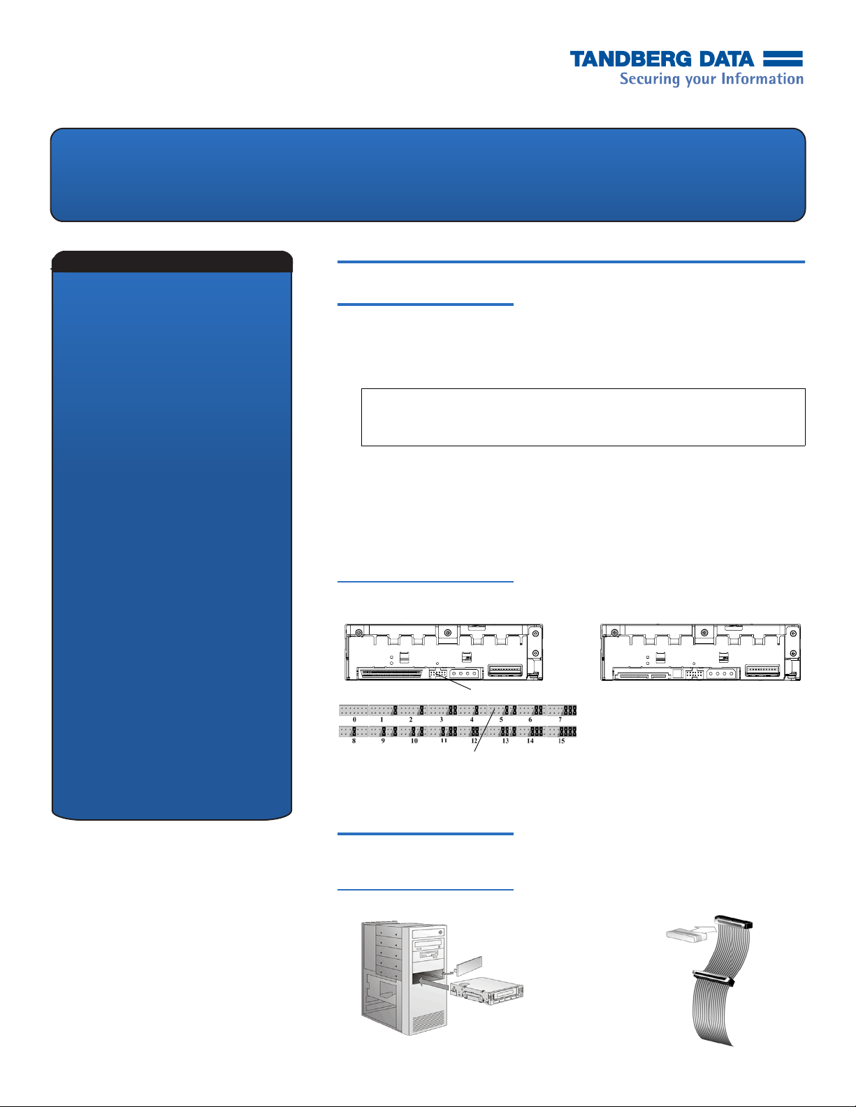
3 For SCSI — Change the SCSI ID for the tape drive, if necessary. See figure 1.
Use the SCSI jumpers to set the SCSI ID. For SATA — There are “no settings to
configure. (See figure 1.)” For complete instructions, see the
Manual
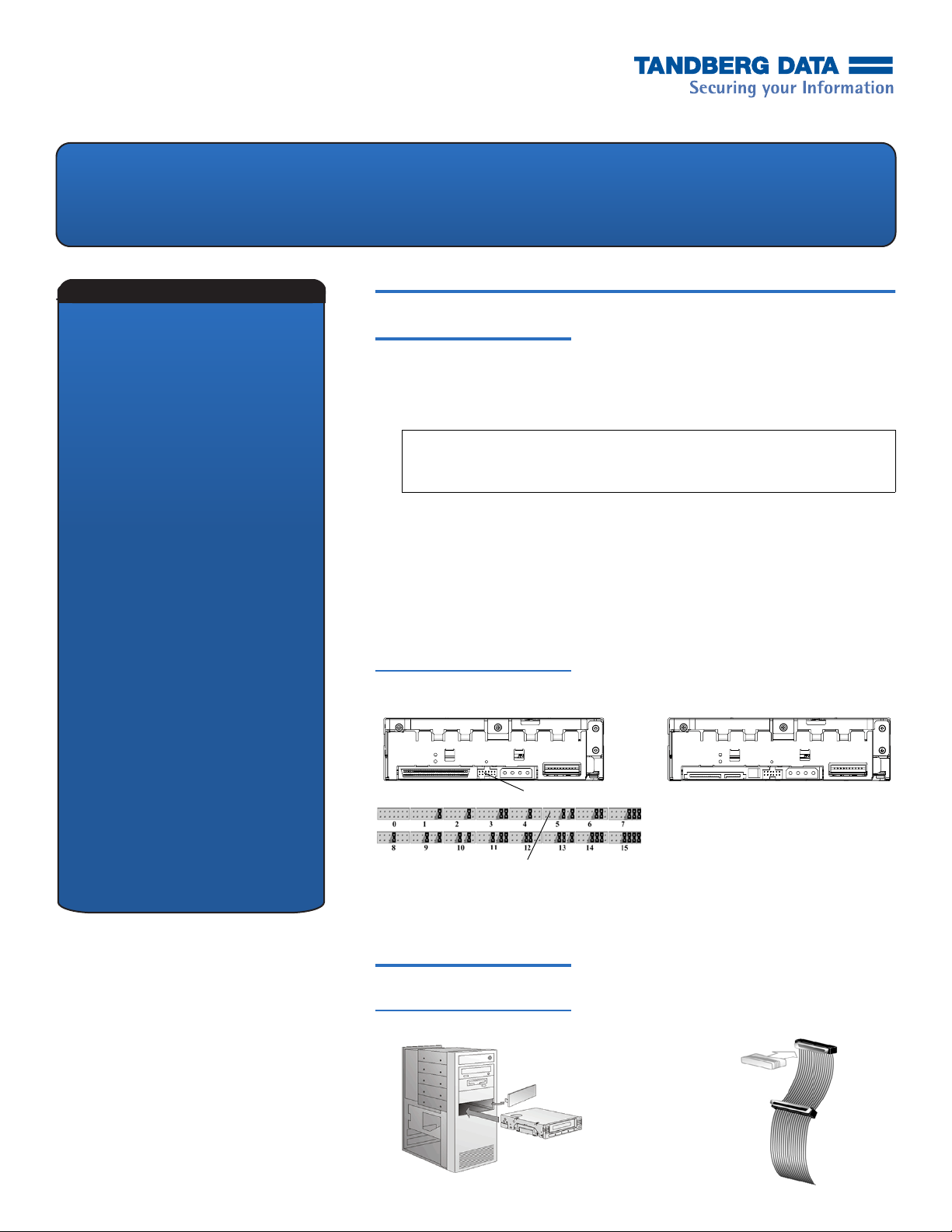
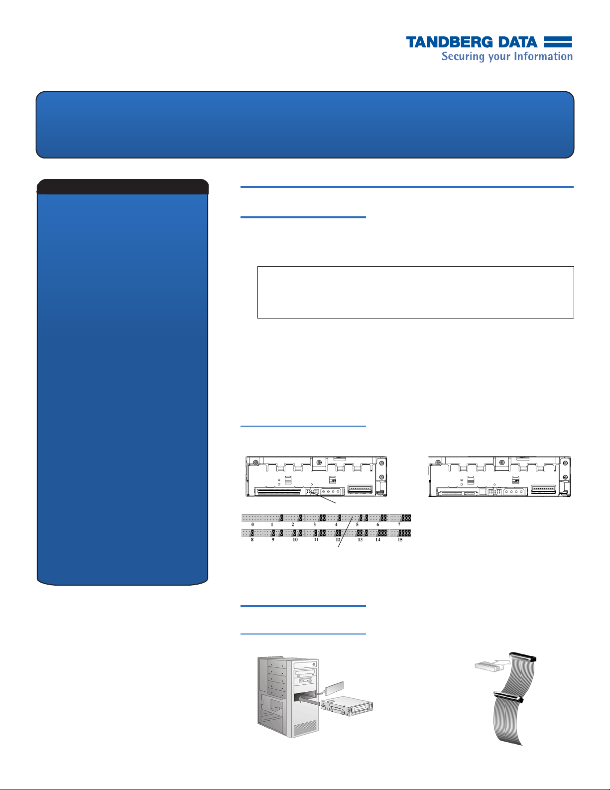
Figure 1 Tape Drives — Rear View
.
0
DLT-V4 Product
SATA Tape Drive — RearSCSI Tape Drive — Rear
SCSI ID jumpers
Factory default SCSI ID
4 Remove the cover from the server or workstation as described in the server or
workstation’s documentation. See figure 2. For SCSI — If necessary, install an
LVD/SE host bus adapter in the server or workstation.
Install the Tape Drive 0
Figure 2 Remove the Cover, Install, and Terminate
1 Install the tape drive in a half-height drive bay. See figure 2.
Page 2
DLT-V4 Tape Drive Quick Start Card
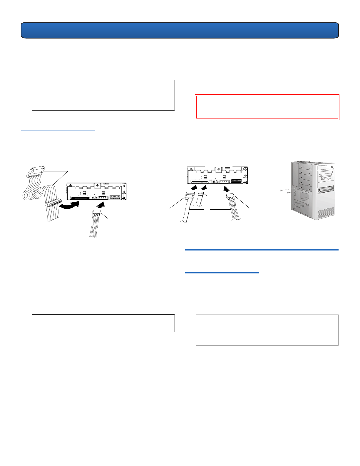
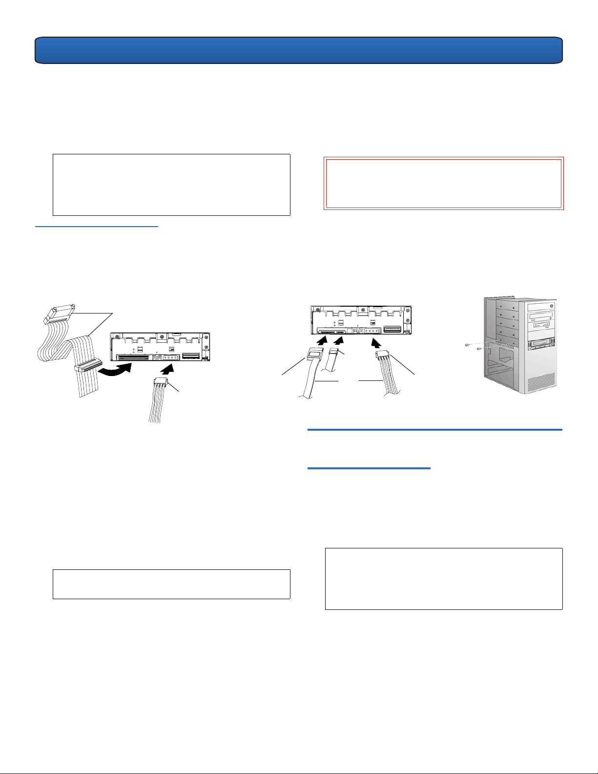
2 For SCSI — Connect an active LVD/SE terminator onto one
end of the SCSI cable, if the tape drive is the last or only
device on the SCSI bus. See
figure 2. If the SCSI cable that
came with the SCSI host bus adapter already has a
terminator built into it, do not use an additional terminator.
NOTE: If the tape drive is not the last or only device on
the SCSI bus, make sure the last device on the SCSI
and
bus is properly terminated
is powered on
whenever you use the tape drive.
Figure 3 Connect the Cables
and Secure the Cover
SCSI Tape Drive — Rear
SCSI cable
(with terminator)
Drive power
cable
SATA Tape Dri ve — Rea r
SATA power
cable
3 For SCSI — Connect the SCSI cable to the tape drive and to
the SCSI host bus adapter. Connect the power cable to the
tape drive. See
figure 3.
4 For SATA — Connect one end of the SATA data cable to the
tape drive and the other end of the SATA data cable to the
either
SATA host bus adapter. Connect
cable
or
drive power cable to the tape drive. See figure 3.
the SATA power
CAUTION: Connect only one power cable to the drive;
connecting both the SATA power cable
and
drive
power cable to the tape drive may damage the drive.
SATA
data cable
or
Drive power
cable
5 Secure the tape drive in the selected server or workstation
with the appropriate mounting screws. See
figure 3.
Contact the computer manufacturer if the server or
workstation uses mounting rails for internal tape drives.
6 Install the cover on the server or workstation. Connect the
power cables to any attached peripheral devices.
7 Power on any attached peripheral devices.
8 Power on the server or workstation and allow its operating
system to start.
NOTE: Turn to the last page for information on
additional resources.
Tabletop Tape Drive 0
Inspect and Prepare the Tape Drive 0
1 Inspect the shipping box and contents of the box for
damage. If you find any damage, report it to the shipping
company.
NOTE: Save the packing materials in case you need to
move or ship the tape drive. You must ship the tape
drive in the original or equivalent packing materials
to preserve your warranty.
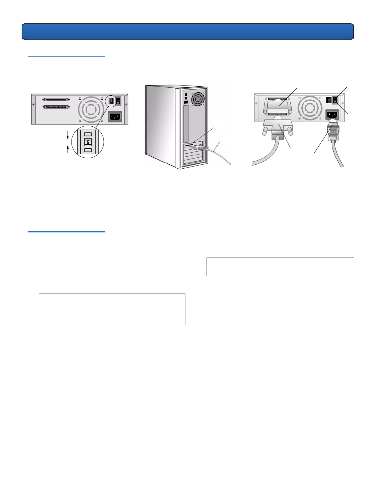
2 Change the SCSI ID for the tape drive, if necessary. See
figure 4. Use a small screwdriver or ballpoint pen to press
the buttons above or below the SCSI ID to increase or
decrease the number. For complete instructions, see the
DLT-V4 Product Manual
.
2
Page 3
DLT-V4 Tape Drive Quick Start Card
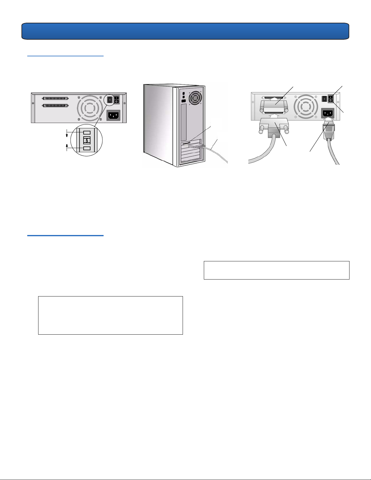
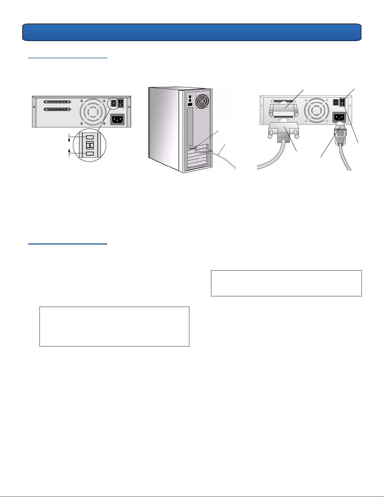
Figure 4 Set the SCSI ID and
Connect the Cables
3 Select a location near the server or workstation that will
host the tape drive. Shut down and power off the host and
all peripheral devices attached to the selected host. If
necessary, install an LVD/SE host bus adapter in the server
or workstation.
Connect the Tape Drive 0
1 Connect the SCSI cable to the tape drive and to the SCSI
host bus adapter — or to the previous device on the SCSI
bus. See
figure 4.
2 Connect an active LVD/SE terminator onto one end of the
tape drive, if it is the last or only device on the SCSI bus.
See figure 4.
SCSI host
adapter
SCSI
cable
Terminator
SCSI
cable
Power
cable
On
3 Ensure that the power switch on the rear panel of the tape
drive is in the OFF position. See
figure 4. Connect the
power cable to the tape drive and plug the power cable in
to the nearest power outlet.
4 Connect the power cables to the host server or workstation
and all peripheral devices.
5 Power on the tape drive and any attached peripheral
devices.
6 Power on the server or workstation and allow its operating
system to start.
NOTE: Turn to the last page of this document for
information on additional resources.
Off
NOTE: If the tape drive is not the last or only device on
the SCSI bus, make sure the last device on the SCSI
and
bus is properly terminated
is powered on
whenever you use the tape drive.
3
Page 4

Sprache
DLT-V4-Bandlaufwerk
Kurzanleitung
Internes Bandlaufwerk 0
Englisch- - - - - - - - - - 1
Deutsch - - - - - - - - - - 4
Spanisch - - - - - - - - - 7
Französisch - - - - - - 10
Japanisch- - - - - - - - 13
Koreanisch- - - - - - - 16
Vereinfachtes
Chinesisch - - - - - - - 19
Bandlaufwerk überprüfen und vorbereiten 0
1 Überprüfen Sie den Versandkarton und dessen Inhalt auf Beschädigungen.
Melden Sie alle Schäden bei der Versandfirma.
ANMERKUNG: Heben Sie die Verpackungsmaterialien für den Fall auf, dass
Sie das Bandlaufwerk umstellen oder versenden müssen. Das
Bandlaufwerk muss zur Bewahrung der Gewährleistung in der Originaloder gleichwertiger Verpackung versandt werden.
2 Wählen Sie einen Server oder eine Workstation, die als Host für das
Bandlaufwerk dienen soll. Fahren Sie den Host herunter und schalten Sie ihn
und alle Peripheriegeräte aus, die an den gewählten Host angeschlossen sind.
3 Für SCSI - Ändern Sie die SCSI-ID für das Bandlaufwerk, wenn erforderlich.
Siehe Abbildung 1. Verwenden Sie die SCSI-Jumper zur Einstellung der SCSIID. Für SATA - "Keine konfigurierbaren Einstellungen. (Siehe Abbildung 1.)”
Vollständige Anweisungen finden Sie im
Abbildung 1 Bandlaufwerke - Rückansicht
SCSI-Bandlaufwerk -
SCSI-Bandlaufwerk - Rückseite
SCSI-ID-Jumper
DLT-V4-Produkthandbuch
SATA-Bandlaufwerk - Rückseite
.
Werkseitige SCSI-ID-Einstellung
4 Entfernen Sie die Abdeckung vom Server oder der Workstation, wie in den
Anweisungen in der Dokumentation des Servers oder der Workstation
beschrieben. Siehe
einen LVD/SE-Hostadapter im Server bzw. der Workstation.
Installieren Sie das Bandlaufwerk 0
Abbildung 2 Abdeckung entfernen, installieren und terminieren
1 Installieren Sie das Bandlaufwerk in einem halbhohen Laufwerksteckplatz.
Abbildung 2.
Siehe
Abbildung 2. Für SCSI — Falls erforderlich installieren Sie
Page 5
DLT-V4-Bandlaufwerk - Kurzanleitungskarte
2 Für SCSI - Schließen Sie einen aktiven LVD/SE-Abschlusswiderstand
an ein Ende des SCSI-Kabels, wenn das Bandlaufwerk das letzte
oder einzige Gerät auf dem SCSI-Bus ist. Siehe
Abbildung 2.
Wenn das SCSI-Kabel, das mit dem SCSI-Hostadapter geliefert
wurde, bereits einen eingebauten Abschlusswiderstand hat,
braucht kein zusätzlicher Abschlusswiderstand verwendet zu
werden.
ANMERKUNG: Wenn das Bandlaufwerk nicht das letzte
oder einzige Gerät auf dem SCSI-Bus ist, ist
sicherzustellen, dass das letzte Gerät auf dem SCSI-
und
Bus ordnungsgemäß terminiert ist
bei
Verwendung des Bandlaufwerks eingeschaltet wird.
Abbildung 3 Kabel anschließen und
die Abdeckung sichern
SCSI-Bandlaufwerk - Rückseite
SCSI-Kabel (mit Abschlusswiderstand)
SATA-Netzkabel
Laufwerknetzkabel
3 Für SCSI - Verbinden Sie das SCSI-Kabel mit dem Bandlaufwerk
und dem SCSI-Hostadapter. Stecken Sie das Netzkabel in das
Bandlaufwerk. Siehe
Abbildung 3.
4 Für SATA - Verbinden Sie ein Ende des SATA-Datenkabels mit dem
Bandlaufwerk und das andere Ende mit dem SATA-Hostadapter.
Verbinden Sie
entweder
das SATA-Netzkabel
oder
Laufwerknetzkabel mit dem Bandlaufwerk. Siehe
VORSICHT: Schließen Sie nur ein Netzkabel am Laufwerk
an; wenn das SATA-Netzkabel
und
das
Laufwerknetzkabel am Bandlaufwerk angeschlossen
werden, kann das Laufwerk beschädigt werden.
SATA-Bandlaufwerk - Rückseite
SATADatenkabel
oder
Laufwerknetzkabel
das
Abbildung 3.
5 Sichern Sie das Bandlaufwerk im gewählten Server oder in
der gewählten Workstation mittels der entsprechenden
Befestigungsschrauben. Siehe Abbildung 3. Setzen Sie sich
mit dem Computerhersteller in Verbindung, wenn der
Server oder die Workstation Einbauschienen für interne
Bandlaufwerke verwendet.
6 Installieren Sie die Abdeckung auf dem Server oder der
Workstation. Verbinden Sie die Netzkabel mit allen
Peripheriegeräten.
7 Schalten Sie alle Peripheriegeräte ein.
8 Schalten Sie den Server oder die Workstation ein und lassen
Sie das Betriebssystem hochfahren.
ANMERKUNG: Auf der letzten Seite finden Sie
Informationen über zusätzliche Ressourcen.
Tabletop-Bandlaufwerk 0
Bandlaufwerk überprüfen und vorbereiten
1 Überprüfen Sie den Versandkarton
und dessen Inhalt auf
Beschädigungen. Melden Sie alle
Schäden bei der Versandfirma.
ANMERKUNG: Heben Sie die Verpackungsmaterialien für
den Fall auf, dass Sie das Bandlaufwerk umstellen
oder versenden müssen. Das Bandlaufwerk muss zur
Bewahrung der Gewährleistung in der Original- oder
gleichwertiger Verpackung versandt werden.
2 Ändern Sie die SCSI-ID für das Bandlaufwerk, falls
erforderlich. Siehe Abbildung 4. Verwenden Sie einen
kleinen Schraubendreher oder Kugelschreiber, um die Tasten
über oder unter der SCSI-ID zu drücken, um die Zahl höher
oder niedriger zu stellen. Vollständige Anweisungen finden
DLT-V4-Produkthandbuch
Sie im
0
.
5
Page 6
DLT-V4-Bandlaufwerk - Kurzanleitungskarte
Abbildung 4 Setzen Sie die SCSI-ID
und schließen Sie die Kabel an
3 Wählen Sie eine Stelle in der Nähe des Server oder der
Workstation für das Bandlaufwerk. Fahren Sie den Host
herunter und schalten Sie ihn und alle Peripheriegeräte aus, die
an den gewählten Host angeschlossen sind. Installieren Sie
gegebenenfalls einen LVD/SELVD/SE-Hostadapter im Server
oder der Workstation.
Bandlaufwerk anschließen 0
1 Verbinden Sie das SCSI-Kabel mit dem Bandlaufwerk und dem
SCSI-Hostadapter - oder mit dem vorigen Gerät auf dem SCSIBus. Siehe Abbildung 4.
2 Schließen Sie einen aktiven LVD/SE-Abschlusswiderstand an ein
Ende des Bandlaufwerks an, wenn es das letzte oder einzige
Gerät auf dem SCSI-Bus ist. Siehe
Abbildung 4.
Abschlusswiderstand
SCSI-Hostadapter
SCSI-Kabel
SCSI-Kabel
Netzkabel
3 Stellen Sie sicher, dass der Netzschalter auf der Rückseite
des Bandlaufwerk in der AUS-Stellung ist. Siehe
Abbildung 4. Schließen Sie das Netzkabel an das
Bandlaufwerk an und stecken Sie das Netzkabel in die
nächstliegende Steckdose.
4 Schließen Sie die Netzkabel an den Hostserver oder die
Workstation und alle Peripheriegeräte an.
5 Schalten Sie das Bandlaufwerk und alle Peripheriegeräte
ein.
6 Schalten Sie den Server oder die Workstation ein und
lassen Sie das Betriebssystem hochfahren.
ANMERKUNG: Auf der letzten Seite finden Sie
Informationen über zusätzliche Ressourcen.
Ein
Aus
ANMERKUNG: Wenn das Bandlaufwerk nicht das letzte
oder einzige Gerät auf dem SCSI-Bus ist, ist
sicherzustellen, dass das letzte Gerät auf dem SCSI-
und
Bus ordnungsgemäß terminiert ist
bei
Verwendung des Bandlaufwerks eingeschaltet wird.
6
Page 7
Idioma
Unidad de cinta DLT-V4
Manual de referencia
Unidad de cinta interna 0
Inglés - - - - - - - - - - - 1
Alemán- - - - - - - - - - - 4
Español - - - - - - - - - - 7
Francés - - - - - - - - - 10
Japonés - - - - - - - - - 13
Coreano - - - - - - - - - 16
Chino simplificado - 19
Inspeccione y prepare la unidad de cinta
1 Inspeccione la caja de embarque y el contenido de la caja para ver si presentan
daños. Si encuentra algún daño, infórmelo a la compañia de envíos.
NOTA:
Guarde los materiales de embalaje por si necesita transportar o enviar la
unidad de cinta. A fin de conservar la garantía, usted debe enviar la unidad
de cinta en los materiales originales de embalaje, o en otros equivalentes.
2 Seleccione el servidor o estación de trabajo que será el host de la unidad de
cinta. Cierre y apague el host seleccionado y todos los dispositivos periféricos
conectados al mismo.
3 En el caso de SCSI, cambie el identificador SCSI de la unidad de cinta, si es
necesario. Consulte la
identificador SCSI. En el caso de SATA, “no es necesario cambiar la
configuración. (Consulte la
consulte el
Figura 1 Unidades de cinta; vista posterior
Unidad de cinta SCSI: parte trasera
Manual de producto de la DLT-V4
0
figura 1. Utilice los puentes de SCSI para establecer el
figura 1).” Para ver instrucciones completas,
.
Unidad de cinta SATA: parte trasera
Puentes de identificación SCSI
Valor predeterminado de fábrica del identificador SCSI
4
Retire la cubierta del servidor o estación de trabajo según se describe en la
documentación de la estación de trabajo o del servidor. Consulte la
Para SCSI: de ser necesario, instale un adaptador de bus de host de LVD/SE
(diferencial de bajo voltaje/extremo único) en el servidor o estación de trabajo.
Instale la unidad de cinta 0
Figura 2 Retire la cubierta, instale y coloque las terminaciones
figura 2
.
Page 8

Folleto de referencia de la unidad de cinta DLT-V4
1 Instale la unidad de cinta en un alojamiento para unidades
de media altura. Consulte la
figura 2.
2 Para SCSI: conecte un terminador de LVD/SE activo en un
extremo del cable SCSI, si la unidad de cinta es el único o el
último dispositivo en el bus SCSI. Consulte la
figura 2. Si el
cable SCSI incluido con el adaptador de bus de host SCSI ya
tiene un terminador incorporado, no use un terminador
adicional.
NOTA: Si la unidad de cinta no es el último ni el único
dispositivo en el bus SCSI, asegúrese que el último
dispositivo del bus SCSI tenga una terminación
y
instalada correctamente
que esté encendido
siempre que se use la unidad de cinta.
Figura 3 Conecte los cables y
asegure la cubierta
Unidad de cinta SCSI: parte trasera
Cable SCSI (con terminador)
3 Para SCSI: conecte el cable SCSI a la unidad de cinta y al
adaptador de bus de host SCSI. Conecte el cable de
alimentación a la unidad de cinta. Consulte la
4 Para SATA: conecte un extremo del cable de datos SATA a la
unidad de cinta y el otro extremo al adaptador de bus de
host SATA. Conecte el cable de alimentación SATA,
el cable de alimentación de la unidad de cinta. Consulte la
figura 3.
PRECAUCIÓN: Conecte solamente un cable de
alimentación a la unidad; si conecta el cable de
y
alimentación SATA
el cable de alimentación de la
unidad de cinta, es posible que la unidad resulte
dañada.
Unidad de cinta SATA: parte trasera
figura 3.
o bien,
Cable de alimentación SATA
Cable de alimentación
de la unidad
5 Asegure la unidad de cinta en el servidor seleccionado, o
estación de trabajo, con los tornillos de montaje adecuados.
Consulte la
figura 3. Si el servidor, o estación de trabajo,
utiliza rieles de montaje para unidades de cinta internas,
póngase en contacto con el fabricante del equipo.
6 Instale la cubierta del servidor o de la estación de trabajo.
Conecte los cables de alimentación de los dispositivos
periféricos del equipo.
7 Encienda los dispositivos periféricos conectados.
8 Encienda el servidor, o estación de trabajo, y deje que el
sistema operativo se inicie.
NOTA: Vaya a la última página para obtener información
acerca de más recursos.
Cable de
datos SATA
o
Cable de
alimentación
de la unidad
Unidad de cinta de escritorio 0
Inspeccione y prepare la unidad de cinta 0
1 Inspeccione la caja de embarque y el contenido de la caja
para ver si presentan daños. Si encuentra algún daño,
infórmelo a la compañia de envíos.
NOTA: Guarde los materiales de embalaje por si necesita
transportar o enviar la unidad de cinta. A fin de
conservar la garantía, usted debe enviar la unidad de
cinta en los materiales originales de embalaje, o en
otros equivalentes.
2 Cambie el identificador SCSI de la unidad de cinta, si es
necesario. Consulte la
destornillador pequeño, o de un bolígrafo, presione los
botones que están arriba o abajo del identificador SCSI para
hacer que el número aumente o disminuya. Para ver
instrucciones completas, consulte el
la DLT-V4
.
figura 4. Con la punta de un
Manual de producto de
8
Page 9

Folleto de referencia de la unidad de cinta DLT-V4
Figura 4 Establezca el identificador
SCSI y conecte los cables
3 Seleccione una ubicación cercana al servidor o estación de
trabajo que funcionará como equipo host de la unidad de
cinta. Cierre y apague el host seleccionado y todos los
dispositivos periféricos conectados al mismo. De ser
necesario, instale un adaptador de bus de host de LVD/SE
(diferencial de bajo voltaje/extremo único) en el servidor o
estación de trabajo.
Conecte la unidad de cinta 0
1 Conecte el cable SCSI a la unidad de cinta y al adaptador
de bus de host SCSI; o al dispositivo anterior en el bus SCSI.
Consulte la
figura 4.
2 Si la unidad de cinta es el único o el último dispositivo en el
bus SCSI, entonces conecte un terminador de LVD/SE activo
en un extremo de la unidad de cinta. Consulte la
figura 4.
Adaptador de
host SCSI
Cable
SCSI
Terminador
Cable
SCSI
Cable de
alimentación
Encendido
Apagado
3 Asegúrese que el interruptor de alimentación del panel
posterior de la unidad de cinta esté en la posición de
apagado. Consulte la
figura 4. Conecte el cable de
alimentación a la unidad de cinta y conéctelo al
tomacorriente más cercano.
4 Conecte los cables de alimentación del servidor host, o
estación de trabajo, y de todos los dispositivos periféricos.
5 Encienda la unidad de cinta y los dispositivos periféricos
conectados.
6 Encienda el servidor, o estación de trabajo, y deje que el
sistema operativo se inicie.
NOTA: Vaya a la última página de este documento para
obtener información acerca de más recursos.
NOTA: Si la unidad de cinta no es el último ni el único
dispositivo en el bus SCSI, asegúrese que el último
dispositivo del bus SCSI tenga una terminación
y
instalada correctamente
que esté encendido
siempre que se use la unidad de cinta.
9
Page 10
Langue
Lecteur de bande DLT-V4
Guide de démarrage rapide
Lecteur de bande interne 0
Anglais- - - - - - - - - - - 1
Allemand - - - - - - - - - 4
Espagnol - - - - - - - - - 7
Français - - - - - - - - - 10
Japonais - - - - - - - - 13
Coréen - - - - - - - - - - 16
Chinois simplifié - - 19
Inspection et préparation du lecteur de bande 0
1 Inspectez la boîte d'expédition et son contenu pour vérifier qu'ils ne sont pas
endommagés. Si vous trouvez un dommage, signalez-le à l'entreprise de transport.
REMARQUE : Conservez les composants de l'emballage au cas où vous
auriez besoin de déménager ou d'expédier le lecteur de bande. Vous
devez expédier le lecteur de bande dans l'emballage d'origine ou un
emballage équivalent pour préserver votre garantie.
2 Sélectionnez un serveur ou un poste de travail pour installer le lecteur de
bande. Arrêtez et coupez l'ordinateur hôte choisi, ainsi que tous les
périphériques qui y sont connectés.
3 Pour SCSI : changez l'ID SCSI du lecteur de bande, si nécessaire. Voir Figure 1.
Utilisez les cavaliers SCSI pour paramétrer l'ID SCSI. Pour SATA : aucun
paramètre n'est à configurer (voir
consultez le
Figure 1 Lecteurs de bande : vue arrière
Arrière du lecteur de bande SCSI
Manuel du produit DLT-V4
Cavaliers d'ID SCSI
Figure 1). Pour le mode d'emploi complet,
.
Arrière du lecteur de bande SATA
ID SCSI par défaut défini en usine
4 Retirez le capot du serveur ou de la station de travail comme décrit dans la
documentation de la station travail ou du serveur. Voir
nécessaire, installez une carte de bus LVD/SE dans le serveur ou le poste de travail.
Installation du lecteur de bande 0
Figure 2 Retrait du couvercle, installation et terminaisons
1 Installez le lecteur de bande dans une baie d'unité de demi-hauteur. Voir
Figure 2.
Figure 2. Pour SCSI : si
Page 11

Dépliant de démarrage rapide du lecteur de bande DLT-V4
2 Pour SCSI : connectez un terminateur LVD/SE actif à l'une
des extrémités du câble SCSI, si le lecteur de bande est le
dernier ou le seul périphérique sur le bus SCSI. Voir
Figure
2. Si le câble SCSI livré avec la carte de bus SCSI possède
déjà un terminateur intégré, n'utilisez pas d'autre
terminateur.
REMARQUE : Si le lecteur de bande n'est pas le dernier ou
le seul périphérique sur le bus SCSI, assurez-vous
que le dernier périphérique sur le bus SCSI possède
et
un terminateur adéquat
qu'il fonctionne chaque
fois que vous utilisez le lecteur de bande.
Figure 3 Connexion des câbles
et fixation du capot
Arrière du lecteur de bande SCSI
Câble SCSI (avec terminateur)
Câble
Câble
d'alimentation
du lecteur
d'alimentation
SATA
3 Pour SCSI : connectez le câble SCSI au lecteur de bande et à
la carte de bus SCSI. Connectez le câble d'alimentation au
lecteur de bande. Voir
Figure 3.
4 Pour SATA : connectez une extrémité du câble de données SATA
au lecteur de bande et l'autre extrémité à la carte de bus SATA.
Connectez
le câble d'alimentation SATA,
soit
soit
d'alimentation du lecteur au lecteur de bande. Voir
ATTENTION : Connectez un seul câble d'alimentation au
lecteur ; en connectant le câble d'alimentation SATA
et
le câble d'alimentation du lecteur, vous pouvez
endommager le lecteur de bande.
Arrière du lecteur de bande SATA
Câble de
données SATA
ou
Câble
d'alimentation
du lecteur
le câble
Figure 3.
5 Fixez le lecteur de bande à l'intérieur du serveur ou de la
station de travail sélectionné à l'aide des vis de fixation
appropriées. Voir
Figure 3. Contactez le fabricant de
l'ordinateur si le serveur ou la station de travail utilise des
rails de montage pour les lecteurs de bande internes.
6 Mettez le capot en place sur le serveur ou la station de
travail. Raccordez les câbles d'alimentation aux
périphériques connectés.
7 Mettez sous tension les périphériques connectés.
8 Mettez sous tension le serveur ou la station de travail, et
attendez le démarrage du système d'exploitation.
REMARQUE : Voir en dernière page pour des
renseignements sur les ressources supplémentaires.
Lecteur de bande de bureau 0
Inspection et préparation du lecteur de bande 0
1 Inspectez la boîte d'expédition et son contenu pour vérifier
qu'ils ne sont pas endommagés. Si vous trouvez un
dommage, signalez-le à l'entreprise de transport.
REMARQUE : Conservez les composants de l'emballage au
cas où vous auriez besoin de déménager ou
d'expédier le lecteur de bande. Vous devez expédier
le lecteur de bande dans l'emballage d'origine ou un
emballage équivalent pour préserver votre garantie.
2 Changez l'ID SCSI du lecteur de bande, si nécessaire. Voir
Figure 4. A l'aide d'un petit tournevis ou un stylo à bille,
appuyez sur les boutons au-dessus et au-dessous de l'ID
SCSI pour augmenter ou diminuer le numéro. Pour le mode
d'emploi complet, consultez le
Manuel du produit DLT-V4
.
11
Page 12
Dépliant de démarrage rapide du lecteur de bande DLT-V4
Figure 4 Paramétrage de l'ID SCSI
et connexion des câbles
3 Sélectionnez un endroit près du serveur ou de la station de
travail qui accueillera le lecteur de bande. Arrêtez et
coupez l'ordinateur hôte choisi, ainsi que tous les
périphériques qui y sont connectés. Si nécessaire, installez
une carte de bus LVD/SE dans le serveur ou la station de
travail.
Connexion du lecteur de bande 0
1 Connectez le câble SCSI au lecteur de bande et à la carte de
bus SCSI, ou bien au périphérique précédent sur le bus
SCSI. Voir Figure 4.
2 Connectez un terminateur LVD/SE actif à l'une des
extrémités du lecteur de bande, si celui-ci est le dernier ou
le seul périphérique sur le bus SCSI. Voir
Figure 4.
Activé
Désactivé
Carte SCSI
Câble SCSI
Terminaison
Câble
SCSI
Câble
d'alimentation
3 Assurez-vous que l'interrupteur d'alimentation sur le
panneau arrière du lecteur de bande est en position
éteinte. Voir
Figure 4. Connectez le câble d'alimentation au
lecteur de bande et branchez le câble d'alimentation sur la
prise de courant la plus proche.
4 Connectez les câbles d'alimentation au serveur ou à
station de travail hôte, ainsi qu'à tous les périphériques.
5 Mettez sous tension le lecteur de bande ainsi que tous les
périphériques éventuellement connectés.
6 Mettez sous tension le serveur ou la station de travail, et
attendez le démarrage du système d'exploitation.
REMARQUE : Voir en dernière page de ce document pour
des renseignements sur les ressources
supplémentaires.
REMARQUE : Si le lecteur de bande n'est pas le dernier ou
le seul périphérique sur le bus SCSI, assurez-vous
que le dernier périphérique sur le bus SCSI possède
et
un terminateur adéquat
qu'il fonctionne chaque
fois que vous utilisez le lecteur de bande.
12
Page 13

言語
DLT-V4 テープ ドライブ
クイック スタート ガイド
内部テープ ドライブ 0
英語 - - - - - - - - - - - - - 1
ドイツ語 - - - - - - - - - - 4
スペイン語 - - - - - - - - 7
フランス語 - - - - - - - 10
日本語- - - - - - - - - - - 13
韓国語- - - - - - - - - - - 16
中国語 ( 簡体字 ) - - 19
テープ ドライブの点検と準備 0
1 運送用の箱とその箱の内容物に損傷などがないことを確認します。 損傷がある
場合は、運送会社に連絡してください。
注:梱包材は、テープ ドライブの移設または運送時のために保管しておい
てください。テープ ドライブを返送する際は、出荷時の梱包材かそれ
に相当するものを使用しなければ、保証が無効になります。
2 テープ ドライブのホストとなるサーバーまたはワークステーションを選択し
ます。選択したホストと、それに接続している周辺機器をすべてシャットダウ
ンし、電源を切ります。
3 SCSI の場合 — 必要に応じて、テープ ドライブの SCSI ID を変更します。
図 1 を参照してください。SCSI ID は、SCSI ジャンパを使用して設定します。
SATA の場合 — 構成する設定はありません。 ( 図 1 を参照。)」詳細説明は、
『DLT-V4 Product Manual (DLT-V4 製品マニュアル )』を参照してください。
図 1 テープ ドライブ — 後部外観
SCSI テープ ドライブ — 後部
SCSI ID ジャンパ
SATA テープ ドライブ — 後部
出荷時設定 SCSI ID
4
サーバーまたはワークステーションの説明書に従って、それぞれのカバーを取り
図 2
外します。
バーまたはワークステーションに LVD/SE ホスト バス アダプタを取り付けます。
テープ ドライブの取り付け 0
図 2 カバーの取り外し、取り付け、終端処理
1 ハーフハイト ドライブ ベイにテープ ドライブを取り付けます。 図 2 を参照
してください。
を参照してください。SCSI の場合 — 必要に応じて、そのサー
Page 14

DLT-V4 テープ ドライブ用クイック スタート ガイド
2 SCSI の場合 — このテープ ドライブが最終端または SCSI
バス上で唯一のデバイスであれば合、アクティブな LVD/SE
ターミネータを SCSI ケーブルの一端に接続します。
図 2
を参照してください。 SCSI ホスト バス アダプタ付属の
SCSI ケーブルにすでにターミネータが内蔵されている場合
は、再度ターミネータを取り付ける必要はありません。
注:テープ ドライブが最終端でなく、SCSI バス上の唯
一のデバイスでない場合は、テープ ドライブを使用
するたびに、SCSI バス上の最終端デバイスが正しく
終端処理され、電源が入っていることを確認してく
ださい。
図 3 ケーブルの接続と
カバーの固定
SCSI テープ ドライブ — 後部
SCSI ケーブル ( ターミネータ付き )
SATA 電源ケー
ドライブ電源
ケーブル
ブル
3 SCSI の場合 — テープ ドライブと SCSI ホスト バス アダ
プタに SCSI ケーブルを接続します。電源ケーブルをテープ
ドライブに接続します。
図 3 を参照してください。
4 SATA の場合 — SATA データ ケーブルの一端をテープドラ
イブに、同じ SATA データ ケーブルの反対側を SATA ホス
ト バス アダプタに接続します。 SATA 電源ケーブルかドラ
イブ電源ケーブルのどちらかをテープ ドライブに接続しま
図 3 を参照してください。
す。
注意: 電源ケーブルを 1 本だけドライブに接続しま
す。テープ ドライブに SATA 電源ケーブル と ドラ
イブ電源ケーブルを同時に接続すると、ドライブが
壊れる可能性があります。
SATA テープ ドライブ — 後部
SATA データ
ケーブル
または
ドライブ電
源ケーブル
5 正しい取り付けネジを使って、選択したサーバーまたはワー
クステーションにテープ ドライブを固定します。 図 3 を参
照してください。 サーバーまたはワークステーションが内蔵
テープ ドライブに取り付けレールを使用している場合は、
そのコンピュータ メーカーにお問い合わせください。
6 サーバーまたはワークステーションにカバーを取り付けま
す。 接続している周辺機器デバイスのすべてに電源ケーブル
を接続します。
7 接続している周辺機器デバイスのすべてに電源を入れます。
8 サーバーまたはワークステーションに電源を入れ、オペレー
ティング システムを起動します。
注:その他のリソースに関する情報は最終ページにあり
ます。
テーブルトップ型テープ ドライブ 0
テープドライブの点検と準備 0
1 梱包と箱の中身に損傷などがないことを確認します。 損傷が
ある場合は、運送会社に連絡してください。
注:梱包材は、テープ ドライブの移設または運送時のた
めに保管しておいてください。テープ ドライブを返
送する際に、出荷時の梱包材かそれに相当するもの
を使用しなければ、保証が無効になります。
2 必要に応じて、テープ ドライブの SCSI ID を変更します。
図 4 を参照してください。 この番号を増減するときは、小
型のドライバやボールペンを使って SCSI ID の上か下にあ
るボタンを押します。 詳細については、『DLT-V4 Product
Manual (DLT-V4 製品マニュアル )』を参照してください。
14
Page 15

DLT-V4 テープ ドライブ用クイック スタート ガイド
図 4 SCSI ID の設定とケー
ブルの接続
3 テープ ドライブのホストになるサーバーまたはワークス
テーションの近くの場所を選びます。選択したホストと、
そのホストに接続している周辺機器をすべてシャットダウ
ンし、電源を切ります。 必要に応じて、サーバーまたは
ワークステーションに LVD/SE ホスト バス アダプタを取
り付けます。
テープ ドライブの接続 0
1 SCSI ケーブルをテープ ドライブと SCSI ホスト バス ア
ダプタに接続するか、SCSI バス上の前のデバイスに接続し
図 4 を参照してください。
ます。
2 このテープ ドライブが最終端または SCSI バス上で唯一の
デバイスであれば、アクティブな LVD/SE ターミネータを
その一端に接続します。
図 4 を参照してください。
SCSI ホスト
アダプタ
SCSI ケーブル
ターミネータ
SCSI
ケーブル
電源ケーブル
オン
オフ
3 テープ ドライブの背面パネルにある電源スイッチがオフの
位置になっていることを確認してください。 図 4 を参照し
てください。 電源ケーブルをテープ ドライブに接続し、そ
の電源ケーブルを近くのコンセントに差し込みます。
4 電源ケーブルをホスト サーバーまたはワークステーション
と、周辺機器デバイスのすべてに接続します。
5 テープ ドライブと、接続している周辺機器デバイスのすべ
てに電源を入れます。
6 サーバーまたはワークステーションに電源を入れ、オペ
レーティング システムを起動します。
注:その他のリソースに関する情報は、この文書の最終
ページにあります。
注:テープドライブが最終端でなく、SCSI バス上の唯
一のデバイスでない場合は、テープ ドライブを使
用するたびに、SCSI バス上の最終端デバイスが正
しく終端設定され、電源が入っていることを確認し
てください。
15
Page 16

언어
DLT-V4 테이프 드라이브
빠른 시작 안내서
내장 테이프 드라이브 0
영어 - - - - - - - - - - - - - 1
독일어- - - - - - - - - - - - 4
스페인어 - - - - - - - - - - 7
프랑스어 - - - - - - - - - 10
일본어- - - - - - - - - - - 13
한국어- - - - - - - - - - - 16
중국어 간체 - - - - - - - 19
테이프 드라이브 검사 및 준비 0
1 손상된 부분이 없는지 포장 상자와 내용물을 검사합니다 . 손상이 발견된 경우에
는 배송 회사에 보고합니다 .
주: 테이프 드라이브를 옮기거나 운송할 때 사용할 수 있도록 포장재를 보
관해 둡니다 . 테이프 드라이브를 운송할 때는 원래의 포장재나 이와 유
사한 포장재를 사용해야 보증을 받을 수 있습니다 .
2 테이프 드라이브를 설치할 서버 또는 워크스테이션을 선택합니다 . 호스트 및 이
와 연결된 주변기기를 모두 종료하고 전원을 차단합니다 .
3 SCSI 의 경우 - 필요한 경우 해당 테이프 드라이브에 대한 SCSI ID 를 변경합니
그림 1 참조 . SCSI 점퍼를 사용하여 SCSI ID 를 설정합니다 . SATA 의 경우
다.
- " 구성 설정할 필요가 없습니다 . ( 그림 1 참조 )” 자세한 지침은
품 설명서
그림 1 테이프 드라이브 - 후면 모양
SCSI 테이프 드라이브 - 후면
를 참조하십시오 .
SATA 테이프 드라이브 - 후면
SCSI ID 점퍼
DLT-V4 제
출고시 기본 설정 SCSI ID
4 서버 또는 워크스테이션 설명서를 참조하여 서버 또는 워크스테이션의 덮개를
제거합니다 .
에 LVD/SE 호스트 버스 어댑터를 설치합니다 .
테이프 드라이브 설치 0
그림 2 덮개 제거 , 설치 및 종단
1 반 높이 드라이브 베이에 테이프 드라이브를 설치합니다 . 그림 2 참조 .
그림 2 참조 . SCSI 의 경우 - 필요하다면 서버 또는 워크스테이션
Page 17

DLT-V4 테이프 드라이브 빠른 시작 카드
2 SCSI 의 경우 - 테이프 드라이브가 SCSI 버스의 최종 장치이
거나 유일한 장치일 경우 , SCSI 케이블의 한쪽 끝에 활성
LVD/SE 터미네이터를 연결합니다 .
그림 2 참조 . SC S I 호 스
트 버스 어댑터와 함께 제공된 SCSI 케이블에 터미네이터가
이미 내장되어 있으면 터미네이터를 추가로 사용하지 마십시
오.
주: 테이프 드라이브가 해당 SCSI 버스의 최종 장치도
아니고 유일한 장치도 아닐 경우 , 그 SCSI 버스의 최
종 장치는 반드시 올바르게 종단되어 있어야 하고
테
이프 드라이브를 사용할 때마다 전원이 켜져 있어야
합니다 .
그림 3 케이블 연결 및 덮개 고정
SCSI 테이프 드라이브 - 후면
SCSI 케이블 ( 터미네이터 포함 )
드라이브
전원 케이블
SATA 전원 케이블
SATA 테이프 드라이브 - 후면
3 SCSI 의 경우 - SCSI 케이블을 테이프 드라이브와 SCSI 호스
트 버스 어댑터에 연결합니다 . 전원 케이블을 테이프 드라이
브에 연결합니다 .
그림 3 참조 .
4 SATA 의 경우 - SATA 데이터 케이블의 한 쪽 끝을 테이프 드
라이브에 연결하고 다른 한 쪽 끝은 SATA 호스트 버스 어댑
터에 연결합니다 .
는
드라이브 전원 케이블을 테이프 드라이브에 연결합니다 .
두 케이블 중 하나 ,
SATA 전원 케이블
또
그림 3 참조 .
주의 : 전원 케이블은 하나만 드라이브에 연결해야 합니
및
다 . SATA 전원 케이블
드라이브 전원 케이블을 함
께 테이프 드라이브에 연결하면 드라이브가 손상될
수 있습니다 .
SATA 데이
터 케이블
또는
드라이브
전원 케이블
5 적합한 장착 나사를 사용하여 테이프 드라이브를 선택된 서버
또는 워크스테이션에 고정시킵니다 . 그림 3 참조 . 해 당 서 버
또는 워크스테이션이 내장 테이프 드라이브용 장착 레일을 사
용하는 경우는 해당 컴퓨터 제조업체에 연락하십시오 .
6 덮개를 서버 또는 워크스테이션에 설치합니다 . 전원 케이블
을 연결된 모든 주변 장치에 연결합니다 .
7 연결된 모든 주변 장치의 전원을 켭니다 .
8 서버 또는 워크스테이션의 전원을 켜고 해당 운영 체제가 시
작되도록 합니다 .
주: 그 외의 리소스에 대한 정보는 마지막 페이지를 참조
하십시오 .
테이블톱 테이프 드라이브 0
테이프 드라이브 검사 및 준비 0
1 손상된 부분이 없는지 포장 상자와 내용물을 검사합니다 . 손
상이 발견된 경우에는 배송 회사에 보고합니다 .
주: 테이프 드라이브를 옮기거나 운송할 때 사용할 수 있
도록 포장재를 보관해 둡니다 . 테이프 드라이브를 운
송할 때는 원래의 포장재나 이와 유사한 포장재를 사
용해야 보증을 받을 수 있습니다 .
2 필요한 경우 해당 테이프 드라이브에 대한 SCSI ID 를 변경합
그림 4 참조 . 작은 드라이버나 볼펜끝으로 SCSI ID 의
니다 .
위 또는 아래 버튼을 누르면 번호가 증가하거나 감소합니다 .
자세한 지침은
DLT-V4 제품 설명서
를 참조하십시오 .
17
Page 18

DLT-V4 테이프 드라이브 빠른 시작 카드
그림 4 SCSI ID 설정 및 케이블 연결
3 테이프 드라이브를 설치할 서버 또는 워크스테이션 가까운
곳을 선택합니다 . 호스트 및 이와 연결된 주변기기를 모두
종료하고 전원을 차단합니다 . 필요하다면 서버 또는 워크스
테이션에 LVD/SE 호스트 버스 어댑터를 설치합니다 .
테이프 드라이브 연결 0
1 SCSI 케이블을 테이프 드라이브와 SCSI 호스트 버스 어댑
터에 연결하거나 - 또는 SCSI 버스의 이전 장치에 연결합니
다. 그림 4 참조 .
2 테이프 드라이브가 SCSI 버스의 최종 장치이거나 유일한 장
치일 경우 , 테이프 드라이브의 한 쪽 끝에 활성 LVD/SE 터
미네이터를 연결합니다 . 그림 4 참조 .
SCSI 호스트
어댑터
SCSI
케이블
터미네이터
SCSI
케이블
전원 케이블
On
Off
3 테이프 드라이브 후면 패널의 전원 스위치는 반드시 OFF 위
치이어야 합니다 . 그림 4 참조 . 전원 케이블을 테이프 드라
이브에 연결하고 전원 케이블을 가장 가까운 전원 콘센트에
꽂습니다 .
4 전원 케이블을 호스트 서버 또는 워크스테이션 그리고 모든
주변 장치에 연결합니다 .
5 테이프 드라이브 및 연결된 모든 주변 장치의 전원을 켭니다 .
6 서버 또는 워크스테이션의 전원을 켜고 해당 운영 체제가 시
작되도록 합니다 .
주: 추가 리소스에 관한 정보는 이 문서의 마지막 페이
지를 참조하십시오 .
주: 테이프 드라이브가 해당 SCSI 버스의 최종 장치도
아니고 유일한 장치도 아닐 경우 , 그 SCSI 버스의
최종 장치는 반드시 올바르게 종단되어 있어야 하
테이프 드라이브를 사용할 때마다 전원이 켜져
고
있어야 합니다 .
18
Page 19

DLT-V4 磁带机
快速入门指南
语言
英语 - - - - - - - 1
内部磁带机 0
检查和准备磁带机 0
1 检查运输箱和箱中物品是否损坏。 如果您发现损坏,请报告运输公司。
德语 - - - - - - - 4
西班牙语 - - - - - 7
法语 - - - - - - - 10
日语 - - - - - - - 13
朝鲜语 - - - - - - 16
简体中文 - - - - - 19
注:保存包装材料,当您移动或运输磁带机时需要使用。 您必须以原始或等
同包装材料运输磁带机以享受您的保修。
2 选择宿主磁带机的服务器或工作站。 关闭并切断主机电源及所有连接到所选主
机的外围设备。
3 对于 SCSI — 请更改磁带机 SCSI ID (如有必要)。 请参阅图 1。 使用 SCSI
跳线设置 SCSI ID。 对于 SATA — 没有要配置的设置。 (请参见图 1。) 有关
完整说明,请参见
图 1 磁带机 — 背面视图
SCSI 磁带机 — 背面
出厂默认 SCSI ID
4 从服务器或工作站上取下盖,如服务器或工作站文档中的描述。 请参阅图 2。
对于 SCSI — 如果必要,请将 LVD/SE 主机总线适配器安装到服务器或工作站
中。
DLT-V4 产品手册
SCSI ID �
。
SATA 磁带机 — 背面
安装磁带机 0
图 2 卸下机盖、安装和端接
1 将磁带机安装在半高磁带机架中。 请参阅图 2。
Page 20

DLT-V4 磁带机快速入门卡
2 对于 SCSI — 将活动 LVD/SE 端接器连接到 SCSI 电缆的一
端,如果磁带机是 SCSI 总线上的最后一个或唯一设备。 请
图 2。 如果 SCSI 主机总线适配器附带的 SCSI 电缆已经
参阅
安装有端接器,则不要使用其他端接器。
注:如果磁带机不是 SCSI 总线上最后一个或唯一设备,
请确保 SCSI 总线上的唯一设备正确端接
且
在使用磁
带机时打开电源。
3 对于 SCSI — 将 SCSI 电缆连接到磁带机和 SCSI 主机总线
适配器。 将电源线连接到磁带机。 请参阅图 3。
图 3 连接电缆并固定机盖
SCSI 磁带机 — 背面
SCSI 电缆 (带端接器)
SATA 电源线
磁带机电源线
4 对于 SATA — 将 SATA 数据线的一端连接到磁带机,另一端
连接到 SATA 主机总线适配器。 将 SATA 电源线或磁带机电源
线连接到磁带机。 请参阅
图 3。
警告:仅将一根电源线连接到磁带机,将 SATA 电源线
磁带机电源线同时连接到磁带机可能损坏磁带机。
SATA 磁带机 — 背面
SATA 数据
线或
磁带机电源线
和
5 以合适的安装螺丝将磁带机固定在所选服务器或工作站中。
请参阅图 3。 如果服务器或工作站使用安装导轨安装内部磁
带机,请联系计算机制造商。
6 安装服务器或工作站的机盖。 将电源线与任何连接的外围设
备相连。
7 打开任何连接的外围设备。
8 打开服务器或工作站并允许其操作系统运行。
注:有关其他资源的信息请转至最后一页。
桌面磁带机 0
检查和准备磁 带机
1 检查运输箱和箱中物品是否损坏。 如果您发现损坏,请报告
运输公司。
2 如有必要,更改磁带机的 SCSI ID。 请参阅图 4。 使用小螺
丝刀或圆珠笔按 SCSI ID 上方或下方的按钮,增大或减小该
数字。 有关完整说明,请参见
0
注:保存包装材料,当您移动或运输磁带机时需要使用。
您必须以原始或等同包装材料运输磁带机以享受您的
保修。
DLT-V4 产品手册
。
20
Page 21

DLT-V4 磁带机快速入门卡
图 4 设置 SCSI ID 和连接电缆
3 选择将承载磁带机的服务器或工作站旁的位置。 关闭并切断
主机电源及所有连接到所选主机的外围设备。 如有必要,将
LVD/SE 主机总线适配器安装到服务器或工作站中。
连接磁带机 0
1 将 SCSI 电缆连接到磁带机和 SCSI 主机总线适配器 ? 或
SCSI 总线上的上一个设备。 请参阅图 4。
2 如果磁带机是 SCSI 总线上的最后一个或唯一设备,请将活
动 LVD/SE 端接器连接到磁带机的一端。 请参阅
图 4。
端接器
SCSI 主机
适配器
SCSI 电
缆
SCSI 电缆
电源线
3 确保磁带机背面板上的电源开关处于关闭位置。 请参阅
图 4。 将电源线连接到磁带机,并将电源线插入到最近的电
源插座。
4 将电源线连接到主机服务器或工作站以及所有外围设备。
5 打开磁带机及所有连接的外围设备的电源。
6 打开服务器或工作站并允许其操作系统运行。
注:有关其他资源的信息,请参见本文档的最后一页。
打开
关闭
注:如果磁带机不是 SCSI 总线上最后一个或唯一设备,
且
请确保 SCSI 总线上的唯一设备正确端接
在使用磁
带机时打开电源。
21
Page 22

©2005 Quantum Corporation. Quantum, the Quantum logo, and the DLTtape logo are all registered trademarks of Quantum Corporation. SDLT and Super DLTtape are trademarks of
Quantum Corporation. Other trademarks may be mentioned herein which belong to other companies.
81-81501-01 A01 November 2005
*81-81501-01 A01*
81-81501-01 A01
 Loading...