

Page 1

TANDBERG GW Data port Command Interface User Guide
TANDBERG 3G GW
Data port Command Interface User Guide
Software version R2
D1320202
TANDBERG
1
Page 2

TANDBERG GW Data port Command Interface User Guide
Table of Contents
1. INTRODUCTION...........................................................................................................................3
2. CONNECTING TO THE DATA PORT COMMAND INTERFACE THROUGH THE RS-
232 PORT..................................................................................................................................................
2.1. HARDWARE AND CABLING............................................................................................................4
2.2. TROUBLESHOOTING ......................................................................................................................5
3. CONNECTING TO THE DATA PORT COMMAND INTERFACE USING TELNET.........6
4. THE TANDBERG 3G GATEWAY COMMANDS.....................................................................7
4.1. INTRODUCTION .............................................................................................................................7
4.1.1. Command format..................................................................................................................... 7
4.1.2. Command types .......................................................................................................................7
4.2. THE COMMANDS ...........................................................................................................................8
4.2.1. System Configuration Commands ...........................................................................................9
4.2.2. General GW Commands........................................................................................................14
4.2.3. System Status Commands ...................................................................................................... 21
4.2.4. Debug Commands .................................................................................................................27
4.2.5. Special Commands ................................................................................................................27
4.3. INDEX COMMANDS .....................................................................................................................32
4
2
Page 3

TANDBERG GW Data port Command Interface User Guide
1. Introduction
The TANDBERG GW Data port Command Interface User Guide contains guidelines on how
to use the textual command interface supported by the GW. The Data port Command
Interface can be accessed through Telnet via the LAN interface or through RS-232 by
connecting a serial cable to the serial interface connector, referred to as the Data port (ref.
chapter
the RS-232 connection.
If, after reading this manual, you require additional information concerning the use of the
TANDBERG GW Data port Command Interface, please contact your local TANDBERG
dealer who will be able to supply you with relevant information for special applications.
2). Three Telnet sessions can be connected to the GW at the same time in addition to
3
Page 4
TANDBERG GW Data port Command Interface User Guide
2. Connecting to the Data port Command Interface through the
RS-232 port.
The RS-232 port is a 9-pin, female, D-sub connector located on the front of the GW. The port
is configured as a DCE (Data Communications Equipment). The RS-232 port is default set to
115200 baud, 8 data bits, none parity and 1 stop bit from factory. The RS-232 port is also
referred to as the Data port.
2.1. Hardware and Cabling
The pin outs for the RS-232 are defined in the following table (the DTE, Data Terminal
Equipment, could be a PC or other device capable of serial communication).
Pin no Signal Description Direction
1 CD Carrier detect To DTE
2 RD Receive data To DTE
3 TD Transmit data From DTE
4 DTR Data terminal ready From DTE
5 Ground
6 DSR Data set ready To DTE
7 RTS Ready to send From DTE
8 CTS Clear to send To DTE
9 RI Ring indicator To DTE
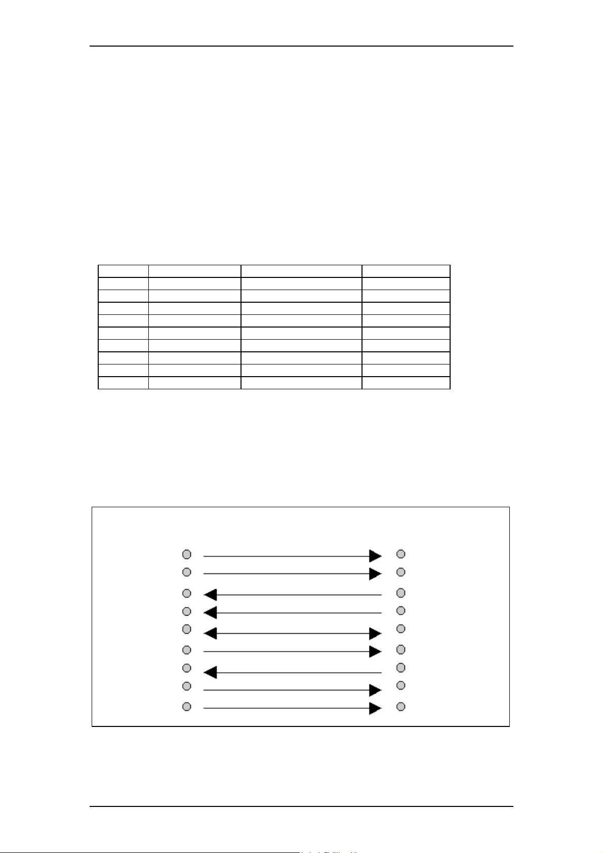
NOTE! A straight through cable should be used between the TANDBERG GW’s RS-232 port
and the DTE.
The figure below illustrates the recommended cable-wiring scheme for connecting the GW to
a PC through RS-232.
TANDBERG GW PC
DCE, 9 pin DTE, 9 pin
1 CD 1 CD
2 RD 2 RD
3 TD 3 TD
4 DTR 4 DTR
5 GND 5 GND
6 DSR 6 DSR
7 RTS 7 RTS
8 CTS 8 CTS
9 RI 9 RI
DTR and RTS are ignored. DSR, CD, and CTS are always asserted, while RI is not used.
4
Page 5

TANDBERG GW Data port Command Interface User Guide
2.2. Troubleshooting
If communication cannot be established between the PC/terminal and the TANDBERG GW’s
Data port the following should be checked:
• Verify that the serial cable is a straight through 9-pin to 9-pin cable
• Confirm that the configuration of the PC/terminal’s serial RS-232 port is identical to
the configuration of the TANDBERG GW RS-232 port.
• Verify that the PC/terminal’s serial RS-232 port is working properly by connecting it
back-to-back to another PC/terminal and send characters in both directions
1
.
1
It requires a null-modem cable to perform this test
5
Page 6

TANDBERG GW Data port Command Interface User Guide
3. Connecting to the Data port Command Interface using Telnet
The TANDBERG 3GW has one LAN port.
The GW’s Telnet server provides access to the Data port Command Interface through a
10/100 base T network interface supporting the TCP/IP protocol.
When connected to the 3G Gateway, type tsh to start a t-shell from the command line. The
Telnet client will receive a welcome message similar to the following:
Welcome to TANDBERG
TANDBERG 3G Gateway Release R2.0 customer
SW Release Date: 2006-03-28
NOTE! If the TANDBERG 3GW is protected by an IP password you will be prompted to enter
this password before you can access the Data port Command Interface via Telnet.
6
Page 7

TANDBERG GW Data port Command Interface User Guide
4. The TANDBERG 3G Gateway Commands
4.1. Introduction
Typing ‘?’ or ‘help’ when connected to the Data Port Command Interface will return a list of
valid commands. The commands are used to control the functions of the 3G Gateway. A
command may be followed by a set of parameters and sub-commands. This chapter gives a
description of all valid commands for the 3G Gateway.
4.1.1. Command format
Typing ‘?’ or ‘help’ after a command will result in a usage text (*h of help response) being
displayed. Usage text gives information about the command format, i.e. valid parameters,
sub-commands etc. An example is shown below (the user input is shown in bold).
Xconf Gateway Service 1 ServiceType ?
*h xConfiguration Gateway Service [1..100] ServiceType:
<None/DiD/IVR/Phonebook>
Numbers 1-100 and None/DiD/IVR/Phonebook are parameters of the configuration (Xconf)
command. Parameters
are arguments upon which the command will operate. Required
parameters are denoted by: < >, while optional parameters are denoted by: [ ]. All possible
values for given parameters are separated with slashes ( / ). For some parameters, only their
names are supplied within the brackets. In these cases specific parameter values need to be
substituted for the parameter names. Allowed parameter values, unless obvious, are provided
when the commands are discussed.
Sub-commands
are commands grouped together within a command. Different sub-commands
within a command may have different parameter sets. In the example below: Address and
Authentication are sub-commands to the command H323Gatekeeper. In the same sense
Mode, ID and Password are sub commands of H323Gatekeeper Authentication.
xconf H323Gatekeeper ?
*h xConfiguration H323Gatekeeper Address: <IPAddr>
*h xConfiguration H323Gatekeeper Authentication Mode: <Auto/Off>
*h xConfiguration H323Gatekeeper Authentication ID: <S: 0, 50>
*h xConfiguration H323Gatekeeper Authentication Password: <S: 0, 50>
NOTE! The Data port Command Interface is not case sensitive.
4.1.2. Command types
The commands can be divided into two major classes:
• Parameter Configuration Commands, Xconf.
• Status Commands, Xstat.
7
Page 8

TANDBERG GW Data port Command Interface User Guide
• User Commands, Xcom.
Parameter Configuration Commands
are commands that set a system parameter to a specific
value. E.g.: The command Xconf telnet mode: "on" enables telnet access on the gateway. If
the command is syntactically correct the GW returns OK, otherwise the GW returns
ERROR. When the parameter is successfully changed, the GW will return the command with
the new value. An example is shown below (the user input is shown in bold).
Xconf telnet mode: "on"
OK
*c xConfiguration Telnet Mode: On
When issuing a Parameter Setting Command without a parameter, the GW will return the
command with the current setting. E.g.:
Xconf telnet mode
*c xConfiguration Telnet Mode: On
OK
Status Commands
are commands that list different sets of system parameters. Status
commands are automatically called when corresponding parameters are being changed.
4.2. The commands
The commands are divided into five groups: System Configuration Commands, General GW
Commands, System Status Commands, Debug Commands and Special Commands.
8
Page 9

TANDBERG GW Data port Command Interface User Guide
4.2.1. System Configuration Commands
Command: Description:
H323Gatekeeper
H323CallSetup
IP
Sets gatekeeper parameters.
NOTE! H.323 services must be set before the GW can be registered to a
gatekeeper.
H323Gatekeeper Address <IPAddr>
or
H323Gatekeeper Authentication Mode <Auto/off>
or
H323Gatekeeper Authentication ID: <S: 0, 50>
Or
H323Gatekeeper Authentication Password: <S: 0, 50>
---
sub-commands:
• Authentication Mode configures the use of authentication
against a gatekeeper.
• Authentication ID Configures the user name used within an
authentication challenge
• Authentication Password sets the password used within the
authentication process.
NOTE! Authentication Password is write only.
Example of H323Gatekeeper feedback:
Xconf H323Gatekeeper Authentication
*c xConfiguration H323Gatekeeper Authentication Mode: Off
*c xConfiguration H323Gatekeeper Authentication ID: ""
Configures for direct or via gatekeeper calling
H323CallSetup Mode: <Direct/Gatekeeper>
--
Example of H323CallSetup feedback:
*c xConfiguration H323CallSetup Mode: Direct
Configures the LAN interfaces when static IP address allocation is used.
NOTE! The GW needs to reboot before the changes will take effect.
IP Assignment: <DHCP/Static>
or
IP Address <IPAddr>
or
IP Address Subnetmask <Subnetmask>
or
IP Address Gateway <IPAddr>
or
IP Address DNS Server [1..5] Address <IPAddr>
or
IP Address DNS Domain Name <S: 0, 64>
---
parameters:
9
Page 10

TANDBERG GW Data port Command Interface User Guide
• DNS Server: Number identifying one of 5 DNS servers which
can be configured. If this parameter is omitted the command
applies to the first configuration (1).
sub-commands:
• Assignment: Selects between DHCP (Dynamic Host
Configuration Protocol) or static IP address allocation. When
DHCP is selected the GW will automatically receive all the
necessary information from the DHCP server. This function
should be used when the GW is connected to a LAN using
DHCP. When using this mode, IP-address and IP-subnet mask
are not used because the DHCP server supplies these parameters.
• Address: Sets the static IP address for the given LAN interface.
• Subnetmask: Sets the subnet mask variable. Subnet mask
defines the network class. If the setting is 255.255.255.0 the local
network will support up to 256 nodes, denoting a class C
network. If the setting is 255.255.0.0 the local network is a class
B network with 65536 addressable nodes.
• Gateway: Sets the gateway IP address. If a gateway is located on
the LAN and the GW needs to reach nodes through this gateway,
the gateway address can be set using the gateway variable (the IP
address of the gateway will be set automatically if the GW is in
DHCP mode)
• Domain Name: Sets the domain name string of which the
gateway is part of. Minimum 0, maximum 64 characters.
Example of IP Address feedback:
*c xConfiguration IP Address: "127.0.0.1"
Ethernet
Sets LAN port speed.
NOTE! The GW needs to reboot before the changes will apply.
Ethernet <speed>
---
parameters:
• speed: auto/10half/10full/100half/100full. The speed is either
set to auto or manually from 10mb half duplex to 100mb full
duplex. When set to auto the GW will automatically negotiate
with the network and use the best available setting.
Example of Ethernet feedback:
*c xConfiguration Ethernet Speed: Auto
ISDN
Defines various ISDN protocol settings.
ISDN IncomingBearerCapability: <UDI/All>
or
ISDN OutgoingBearerCapability: <H324m/UDI>
or
ISDN BRI SwitchType: <NI/ATT/Euro/Japan>
or
ISDN PRI SwitchType: <NI/ATT/Euro/Japan>
or
ISDN PRI Interface LowChannel: <1..31>
---
Parameters:
sub-commands:
10
Page 11

TANDBERG GW Data port Command Interface User Guide
Within ISDN different bearer capabilities are used to signal the type of date
(Voice, Data, H320, H324M), which is used by switches and other
equipment to determine what to do with the data or the call (compand
neglect etc).
• IncomingBearerCapability: sets the ISDN bearer capability of
the incoming 3G calls. In some situations the non correct UDI
bearer is used in stead of the right H324M capability. This setting
makes it possible to accept incoming 3G calls both situations..
• OutgoingBearerCapability: sets the ISDN bearer capability for
the outgoing 3G calls. In some situations the switch does not
accept calls which use the correct H324M capability. This setting
makes it possible to use the gateway in these situations (UDI).
• BRI SwitchType: Sets the switch type of the gateway in case of a
BRI version.
• PRI SwitchType: Sets the switch type of the gateway in case of a
PRI version.
• PRI Interface LowChannel: This parameter sets the lowest
channel to start with when making outgoing call (to 3G handsets)
Example of ISDN feedback:
*c xConfiguration ISDN IncomingBearerCapability: All
*c xConfiguration ISDN OutgoingBearerCapability: UDI
*c xConfiguration ISDN BRI SwitchType: Euro
*c xConfiguration ISDN PRI SwitchType: Euro
*c xConfiguration ISDN PRI Interface LowChannel: 1
E1
E1 is the configuration of CRC4 for the ISDN PRI lines.
E1 Interface CRC4: <On/Off>
Example of E1 feedback:
*c xConfiguration E1 Interface CRC4: Off
HTTPS
Enables or disables access to HTTPS services.
NOTE! Changes become effective after reboot
HTTPS Mode <On/Off>
Example of HTTPS feedback:
*c xConfiguration HTTPS Mode: Off
HTTP
Enables or disables access to HTTP services.
NOTE! Changes become effective after reboot.
HTTP Mode <On/Off>
Example of HTTP feedback:
*c xConfiguration HTTP Mode: On
SNMP
Configures the SNMPmib.
Note! For more information about SNMP please read the TANDBERG
SNMP application note.
SNMP Mode < On/Off/ReadOnly/TrapsOnly >
or
SNMP CommunityName: <S: 0, 16>
or
SNMP SystemContact: <S: 0, 70>
or
11
Page 12

TANDBERG GW Data port Command Interface User Guide
SNMP SystemLocation: <S: 0, 70>
or
SNMP HostIPAddr [1..3]: <IPAddr>
---
parameters:
• Mode: < On/Off/ReadOnly/TrapsOnly >
• Community Name: Text string of maximum 16 characters.
• System Contact: Text string of maximum 70 characters
• System Location: Text string of maximum 70 characters
• Host IP Addr: The IP addresses of max 3 SNMP trap hosts
sub-commands:
• Mode enables or sets the mode of SNMP support
• Community Name is used to authenticate SNMP requests.
SNMP requests must have this ‘password’ in order to receive a
response from the SNMP agent in the gateway.
• System Contact, Used to identify the system contact via SNMP
tools such as HPOpenView or TANDBERG Management Suite
• System Location Used to identify system location via SNMP
tools such as HPOpenView or TANDBERG Management Suite
• Host IP Addr identifies the IP-address of the SNMP manager.
Up to three different SNMP Trap Hosts can be defined. Your
LAN administrator should provide the correct values for these
fields
Example of SNMP feedback:
*c xConfiguration SNMP Mode: On
*c xConfiguration SNMP CommunityName: "public"
*c xConfiguration SNMP SystemContact: ""
*c xConfiguration SNMP SystemLocation: ""
*c xConfiguration SNMP HostIPAddr 1: "127.0.0.1"
*c xConfiguration SNMP HostIPAddr 2: "127.0.0.1"
*c xConfiguration SNMP HostIPAddr 3: "127.0.0.1"
SSH
Enables or disables SSH interface on the 3G GW
SSH Mode: <On/Off>
---
Example of SSH feedback:
*c xConfiguration SSH Mode: On
TELNET
Enables or disables telnet interface on the 3G GW
Telnet Mode: <On/Off>
---
Example of TELNET feedback:
*c xConfiguration Telnet Mode: On
SystemUnit
Sets the 3G GW name and password
SystemUnit Name: <S: 0, 50>
or
SystemUnit Password: <S: 0, 16>
---
Parameters:
• Name: Text string of maximum 50 characters
• Password: Text string of maximum 16 characters
12
Page 13

TANDBERG GW Data port Command Interface User Guide
sub-commands
• Name, sets the name of the 3G Gateway
• Password, sets the password of the 3G gateway
Example of SystemUnit feedback:
*c xConfiguration SystemUnit Name: ""
13
Page 14

TANDBERG GW Data port Command Interface User Guide
4.2.2. General GW Commands
Command: Description:
Gateway
This command is used to configure the 3G gateway dialling rules, like for
example direct inward dialling, H323 call prefixes and dial in numbers. It is
possible to define 100 services, each with the parameters:
• Description indicates the user applied name of the service
• InNetType indicates the dial in for this particular service
configuration.
• OutNetType indicates the dial out for this particular service
configuration
• InPrefix will be used for matching the incoming called
number/address and is used to register with the gatekeeper in case
call type is H323
• InPostfix is the part of the dialed number that will be
removed/replaced.
• ServiceType indicates whether this service is a direct inward dialing,
a phonebook or an IVR service is.
• OutPrefix and OutPostfix will be used to construct the
number/address that will be called (if applicable) using this service.
Service [1..100] Description: <S: 0, 30>
or
Service [1..100] InNetType: <H324m/3G/H323 >
or
Service [1..100] OutNetType: <H324m/3G/H323 >
or
Service [1.. 100] InPrefix: <S: 0, 30>
or
Service [1.. 100] InPostfix: <S: 0, 30>
or
Service [1.. 100] ServiceType: < None/DiD/IVR/Phonebook >
or
Service [1.. 100] OutPrefix: <S: 0, 30>
or
Service [1.. 100] OutPostfix: <S: 0, 30>
or
LoadLimit: <0..100>
---
Parameters:
sub-commands:
• Description: This is a friendly name for the service configured like
for example 3G to H323 and 3G hotline to H323
• InNetType.
• OutNetType
• InPrefix.
• InPostfix
• ServiceType
• OutPrefix
• OutPostfix
• LoadLimit The GW will signal busy to the gatekeeper when the
current load on the GW reaches this limit. The current system load
can be monitored by the status command SystemLoad
14
Page 15

TANDBERG GW Data port Command Interface User Guide
Example of Gateway feedback:
*c xConfiguration Gateway Service 1 Description: ""
*c xConfiguration Gateway Service 1 ServiceType: DiD
*c xConfiguration Gateway Service 1 InNetType: H324m/3G
*c xConfiguration Gateway Service 1 InPrefix: 6789""
*c xConfiguration Gateway Service 1 InPostfix: ""
*c xConfiguration Gateway Service 1 OutNetType: H324m/3G
*c xConfiguration Gateway Service 1 OutPrefix: "5"
*c xConfiguration Gateway Service 1 OutPostfix: ""
*c xConfiguration Gateway LoadLimit: 100
When dialling the number 67890000 there will be a match with “0000” as the
significant number. The H.323 number to call is: 50000 (construction: prefix +
significant numbers + postfix). When dialling number 67894321 this will
match with “4321” as the significant number. The H.323 number to call is:
54321 (construction: prefix + significant numbers + postfix)
ExternalManager
This command sets the path and address of TMS server.
ExternalManager Path: <S: 0, 255>
or
ExternalManager Address: <IPAddr>
--
sub-commands:
• Path
• Address, the IP address of the manager
Example of ExternalManager feedback
*c xConfiguration ExternalManager Path:
"tms/public/external/management/SystemManagementService.asmx"
*c xConfiguration ExternalManager Address: ""
CorporateDirectory
This command sets the path and address of the Corporate Directory
(phonebook) server.
CorporateDirectory Address: <IP Addr>
or
CorporateDirectory Path: <S: 0, 255>
--
sub-commands:
• Path, the path of the HTTP request
• Address, the IP address of the manager
Example of Corporate Directory feedback
*c xConfiguration CorporateDirectory Path:
"tms/public/external/phonebook/PhoneBookService.asmx"
*c xConfiguration CorporateDirectory Address: ""
NTP
This command sets the address of the NTP server.
NTP Address: <IP Addr>
--
sub-commands:
• Address, the IP address of the server
Example of NTP feedback
*c xConfiguration NTP Address: "131.188.3.220"
Options
View and adapt option keys
15
Page 16

TANDBERG GW Data port Command Interface User Guide
NOTE! The GW needs to reboot before the changes will take effect.
Options [1 .. 64] Key: <S: 0, 90>
---
sub-commands:
• Key: Option key for e.g. BRI, PRI or SS7 trunks.
Example of Options feedback:
*c xConfiguration Options 1 Key: "115201SS7-1-55C3EBB7"
*c xConfiguration Options 2 Key: "115201P1-1-6A96DAA4"
*c xConfiguration Options 3 Key: "115201P1-2-1811D4FA"
*c xConfiguration Options 4 Key: "115201P1-3-79828C53"
*c xConfiguration Options 5 Key: "115201P1-4-B5E5BD4A"
SIP
Configures the SIP Proxy Mode and Address settings.
Mode <On/Off>
or
Proxy Address <IPAddr>
or
Proxy Port: <1 .. 65534>
---
sub-commands:
• Mode: If Mode = On the 3G Gateway is registered with the Proxy
server
• Address: IP address of the Proxy server the 3G Gateway is to be
registered to.
• Port: Port number of the Proxy server.
Example of SIP feedback:
*c xConfiguration SIP Proxy Mode: Off
*c xConfiguration SIP Proxy Address: "127.0.0.1"
*c xConfiguration SIP Proxy Port: 5060
SS7
Configures the SS7 Signalling for all 3G Gateway trunks
NOTE! The GW needs to reboot before the changes will take effect.
OPC: <0 .. 16383>
NetworkIndicator: <International0/International1/National0/National1>
Law: <ALaw/ULaw>
LinkSet [1 .. 2] Mode: <On/Off>
LinkSet [1 .. 2] DPC: <0 .. 16383>
LinkSet [1 .. 2] Link [1 .. 2] Mode: <On/Off>
LinkSet [1 .. 2] Link [1 .. 2] Trunk: <1 .. 4>
16
Page 17

TANDBERG GW Data port Command Interface User Guide
LinkSet [1 .. 2] Link [1 .. 2] Timeslot: <1 .. 31>
LinkSet [1 .. 2] Link [1 .. 2] SLC: <0 .. 15>
Trunk [1 .. 4] Mode: <On/Off>
Trunk [1 .. 4] DPC: <0 .. 16383>
Trunk [1 .. 4] CircuitIdentificationCode: <0 .. 16383>
Route [1 .. 8] DPC: <0 .. 16383>
Route [1 .. 8] Priority: <1 .. 4>
Route [1 .. 8] LinkSet: <Off/1/2>
---
sub-commands:
• OPC: A number between 0-2
14
, which uniquely identifies a signaling
point, in this case the 3G Gateway, within a telephone network. This
number consists of three parts, i.e. a network, cluster and member
number, and will be provided by the network operator.
• NetworkIndicator:,A two bit data field within the Service
Information Octet of the Message Signal Unit that permits
discrimination between national and international messages.
• Law: audio standard: Either ALAW or ULAW. An a-law algorithm
is a standard companding, i.e. compressing and expanding, algorithm,
used in European digital communication systems to optimize, i.e.
modify, the dynamic range of an analog signal for digitizing. The µlaw algorithm is similar to a-law and used in North American and
Japanese systems.
• LinkSet Mode: Enable or disable linksets.
• LinkSet DPC: Uniquely identifies the destination signaling point of
the link. This can differ from the DPC of the trunk, e.g. the DPC of a
Signaling Transfer Point (STP), see example 2 below.
• LinkSet Link Mode: Enable a link in a link set.
• LinkSet Link Trunk: Number of the trunk (1 - 4) in which a time
slot is reserved for signaling.
• LinkSet Link Timeslot: Number of the time slot, within
aforementioned trunk, reserved for signaling.
• LinkSet Link SLC: A Signaling Link Code is a unique link number
provided by the network operator to identify a link.
• Trunk Mode: Enable or disable a trunk.
• Trunk DPC: Uniquely identifies the destination signaling point of
the trunk. It will be provided by the network operator.
• Trunk CircuitIdentificationCode: The Circuit Identification Code
is a unique identifier for a data time slot in a cable (trunk). In this
case the CIC acts as base address and can be defined for each SS7
trunk and sets the first time-slot number of the respective SS7 trunk.
• Route DPC: Unique identifier indicating the destination signaling
point of a trunk.
• Route Priority: Priority level of the route to the destination signaling
point. Fail-over signaling paths will be followed according to this
priority.
• Route LinkSet: Indicates the link to the destination signaling point
according to the above mentioned priority setting.
For more details on the sub-commands please read the chapter about SS7
17
Page 18

TANDBERG GW Data port Command Interface User Guide
in the 3G Gateway User Manual.
Example of SS7 feedback:
*c xConfiguration SS7 OPC: 0
*c xConfiguration SS7 NetworkIndicator: National0
*c xConfiguration SS7 Law: ALaw
*c xConfiguration SS7 LinkSet 1 Mode: Off
*c xConfiguration SS7 LinkSet 1 DPC: 0
*c xConfiguration SS7 LinkSet 1 Link 1 Mode: Off
*c xConfiguration SS7 LinkSet 1 Link 1 Trunk: 0
*c xConfiguration SS7 LinkSet 1 Link 1 Timeslot: 0
*c xConfiguration SS7 LinkSet 1 Link 1 SLC: 0
*c xConfiguration SS7 LinkSet 1 Link 2 Mode: Off
*c xConfiguration SS7 LinkSet 1 Link 2 Trunk: 0
*c xConfiguration SS7 LinkSet 1 Link 2 Timeslot: 0
*c xConfiguration SS7 LinkSet 1 Link 2 SLC: 0
*c xConfiguration SS7 LinkSet 2 Mode: Off
*c xConfiguration SS7 LinkSet 2 DPC: 0
*c xConfiguration SS7 LinkSet 2 Link 1 Mode: Off
*c xConfiguration SS7 LinkSet 2 Link 1 Trunk: 0
*c xConfiguration SS7 LinkSet 2 Link 1 Timeslot: 0
*c xConfiguration SS7 LinkSet 2 Link 1 SLC: 0
*c xConfiguration SS7 LinkSet 2 Link 2 Mode: Off
*c xConfiguration SS7 LinkSet 2 Link 2 Trunk: 0
*c xConfiguration SS7 LinkSet 2 Link 2 Timeslot: 0
*c xConfiguration SS7 LinkSet 2 Link 2 SLC: 0
*c xConfiguration SS7 Trunk 1 Mode: Off
*c xConfiguration SS7 Trunk 1 DPC: 0
*c xConfiguration SS7 Trunk 1 CircuitIdentificationCode: 0
*c xConfiguration SS7 Trunk 2 Mode: Off
*c xConfiguration SS7 Trunk 2 DPC: 0
*c xConfiguration SS7 Trunk 2 CircuitIdentificationCode: 0
18
Page 19

TANDBERG GW Data port Command Interface User Guide
*c xConfiguration SS7 Trunk 3 Mode: Off
*c xConfiguration SS7 Trunk 3 DPC: 0
*c xConfiguration SS7 Trunk 3 CircuitIdentificationCode: 0
*c xConfiguration SS7 Trunk 4 Mode: Off
*c xConfiguration SS7 Trunk 4 DPC: 0
*c xConfiguration SS7 Trunk 4 CircuitIdentificationCode: 0
*c xConfiguration SS7 Route 1 DPC: 0
*c xConfiguration SS7 Route 1 Priority: 0
*c xConfiguration SS7 Route 1 LinkSet: Off
*c xConfiguration SS7 Route 2 DPC: 0
*c xConfiguration SS7 Route 2 Priority: 0
*c xConfiguration SS7 Route 2 LinkSet: Off
*c xConfiguration SS7 Route 3 DPC: 0
*c xConfiguration SS7 Route 3 Priority: 0
*c xConfiguration SS7 Route 3 LinkSet: Off
*c xConfiguration SS7 Route 4 DPC: 0
*c xConfiguration SS7 Route 4 Priority: 0
*c xConfiguration SS7 Route 4 LinkSet: Off
*c xConfiguration SS7 Route 5 DPC: 0
*c xConfiguration SS7 Route 5 Priority: 0
*c xConfiguration SS7 Route 5 LinkSet: Off
*c xConfiguration SS7 Route 6 DPC: 0
*c xConfiguration SS7 Route 6 Priority: 0
*c xConfiguration SS7 Route 6 LinkSet: Off
*c xConfiguration SS7 Route 7 DPC: 0
*c xConfiguration SS7 Route 7 Priority: 0
*c xConfiguration SS7 Route 7 LinkSet: Off
*c xConfiguration SS7 Route 8 DPC: 0
*c xConfiguration SS7 Route 8 Priority: 0
*c xConfiguration SS7 Route 8 LinkSet: Off
19
Page 20

TANDBERG GW Data port Command Interface User Guide
VideoPortal
Registers the 3G Gateway with the VideoPortal
NOTE! The GW needs to reboot before the changes will take effect.
Mode <On/Off>
or
System [1 .. 2] IP Address <IPAddr>
---
sub-commands:
• Mode: If Mode = On the 3G Gateway is registered with 1 or 2 video
portals
• Address: IP address of the Video Portal the 3G Gateway is to be
registered to.
Example of VideoPortal feedback:
*c xConfiguration VideoPortal Mode: On
*c xConfiguration VideoPortal System 1 Address: "10.31.1.8"
*c xConfiguration VideoPortal System 2 Address: "127.0.0.1"
20
Page 21

TANDBERG GW Data port Command Interface User Guide
4.2.3. System Status Commands
Command: Description:
SystemUnit
Displays information regarding the physical system
SystemUnit
Status format:
<ProductType>
<Uptime>
<Software
Version>
Name>
ReleaseDate>
Configuration
Telephony:>
VideoTelephony:>
<Hardware :
Version>
SerialNumber>
MainBoard>
AdditionalBoard>
Configuration:
PRI>
TemperatureCelcius>
TemperatureFahrenheit>
---
Parameters:
• ProductType, the name of the product, e.g. 3G Gateway
• Uptime, the time the system is running since the last reboot in seconds
• Software
o Version, the unique name of the software
o Name,
o ReleaseDate, the time and date of the build of this software
o Configuration
• Telephony, the amount of supported voice channels
• VideoTelephony, the amount of supported video
channels
• Hardware
o Version, software ID
o SerialNumber, software serial number
o MainBoard, the ID of the main board
o AdditionalBoard, indicates extra boards in the box
o Configuration:
• PRI, the amount of PRIs in the target system
• BRI, the amount of BRIs in the target system
• TemperatureCelcius, temperature of the main board in Celcius
• TemperatureFahrenheit, temperature of the main board in Fahrenheit
Example of SystemUnit feedback:
*s SystemUnit:
ProductType: "TANDBERG 3G Gateway"
Uptime: 15123
Software:
Version: "R2.0Beta8 (TEST SW)"
Name: "test"
ReleaseDate: "2006-04-21, 17:54, rsc"
Configuration:
21
Page 22

TANDBERG GW Data port Command Interface User Guide
Telephony: 0
VideoTelephony: 0
Hardware:
Version: "3GW 1.0"
SerialNumber: "43A00001"
MainBoard: ""
AdditionalBoard: ""
Configuration:
PRI:41
TemperatureCelcius: NA
TemperatureFahrenheit: NA
*s/end
Ethernet
Displays the configuration of the Ethernet interface
Ethernet
Status format:
< MacAddress>
<Speed>
---
Parameters:
• MacAddress, The mac address of the Ethernet interface
• Speed, The speed of the interface, possible values are
Auto/10half/10full/100half/100full.
Example of Ethernet feedback
*s Ethernet:
MacAddress: "00:0E:0C:5C:B5:7D"
Speed: 100full
*s/end
IP
Displays the IP configuration of the gateway
IP
Status format:
<Address>
<SubnetMask>
<Gateway>
<DNS:
Server 1:
Address>
Server 2:
Address>
Server 3:
Address>
Server 4:
Address>
Server 5:
Address>
Domain:
Name>
---
Parameters:
• Address, the IP address of the gateway
• SubnetMask, the subnetmask used for the connected network
• Gateway, the gateway to route traffic to an IP number outside the
connected network
22
Page 23

TANDBERG GW Data port Command Interface User Guide
• DNS Server [1.. 5] Address, the IP numbers of maximum 5 DNS
servers
• Domain, the name of the domain the gateway is part of.
Example of IP feedback:
*s IP:
Address: "10.31.0.5"
SubnetMask: "255.255.248.0"
Gateway: "10.31.0.1"
DNS:
Server 1:
Address: "127.0.0.1"
Server 2:
Address: "127.0.0.1"
Server 3:
Address: "127.0.0.1"
Server 4:
Address: "127.0.0.1"
Server 5:
Address: "0.0.0.0"
Domain:
Name: ""
*s/end
H323Gatekeeper
Displays the status of the connection with the gatekeeper.
H323Gatekeeper
Status format:
<Status>
<Address>
<Port>
---
Parameters:
• Status, indicates whether the 3G Gateway is registered with the
gatekeeper
• Address, the IP address of the connected gatekeeper
• Port, the gatekeeper port the gateway is connected with
Example of H323Gatekeeper feedback:
*s H323Gatekeeper (status=Registered):
Address: "10.47.9.1"
Port: 1719
*s/end
ExternalManager
Displays the configuration of the external management system (e.g. TMS).
ExternalManager:
Status format:
<Address>
<Protocol>
<URL>
---
Parameters:
• Address, The IP address of the external management system
• Protocol, the protocol used to access the management system
• URL, the URL on the management system that should be opened by
the gateway in case of status updates
23
Page 24

TANDBERG GW Data port Command Interface User Guide
Example of ExternalManager feedback:
*s ExternalManager:
Address: ""
Protocol: HTTP
URL: "tms/public/external/management/SystemManagementService.asmx"
*s/end
BRI [1..4]
Displays the status of the BRI lines
BRI
Parameters:
• BRI [1..4] indicating the status of the different BRI lines
Example of BRI feedback:
*s BRI 1 (ready=False):
Layer1Alarm: On
Layer2Alarm: On
*s/end
*s BRI 2 (ready=False):
Layer1Alarm: On
Layer2Alarm: On
*s/end
*s BRI 3 (ready=False):
Layer1Alarm: On
Layer2Alarm: On
*s/end
*s BRI 4 (ready=True):
Channel 1 (type=BChannel, status=Idle): /
Channel 2 (type=BChannel, status=Idle): /
*s/end
PRI [1..4]
Displays the status of the PRI line
PRI
Parameters:
• PRI [1..4] indicating the status of the different PRI lines
Example of PRI feedback
*s PRI 1 (ready=True):
BChannelsTotal: 30
BChannelsFree: 30
Channel 1 (type=BChannel, status=Idle): /
Channel 2 (type=BChannel, status=Idle): /
Channel 3 (type=BChannel, status=Idle): /
Channel 4 (type=BChannel, status=Idle): /
Channel 5 (type=BChannel, status=Idle): /
Channel 6 (type=BChannel, status=Idle): /
Channel 7 (type=BChannel, status=Idle): /
Channel 8 (type=BChannel, status=Idle): /
Channel 9 (type=BChannel, status=Idle): /
Channel 10 (type=BChannel, status=Idle): /
Channel 11 (type=BChannel, status=Idle): /
Channel 12 (type=BChannel, status=Idle): /
Channel 13 (type=BChannel, status=Idle): /
Channel 14 (type=BChannel, status=Idle): /
24
Page 25

TANDBERG GW Data port Command Interface User Guide
Channel 15 (type=BChannel, status=Idle): /
Channel 16 (type=DChannel, status=NA): /
Channel 17 (type=BChannel, status=Idle): /
Channel 18 (type=BChannel, status=Idle): /
Channel 19 (type=BChannel, status=Idle): /
Channel 20 (type=BChannel, status=Idle): /
Channel 21 (type=BChannel, status=Idle): /
Channel 22 (type=BChannel, status=Idle): /
Channel 23 (type=BChannel, status=Idle): /
Channel 24 (type=BChannel, status=Idle): /
Channel 25 (type=BChannel, status=Idle): /
Channel 26 (type=BChannel, status=Idle): /
Channel 27 (type=BChannel, status=Idle): /
Channel 28 (type=BChannel, status=Idle): /
Channel 29 (type=BChannel, status=Idle): /
Channel 30 (type=BChannel, status=Idle): /
Channel 31 (type=BChannel, status=Idle): /
*s/end
Feedback [1.. 3]
Lists the URL and feedback expressions registered for the given Feedback ID
Feedback
Parameters:
• status: on/off Indicates if there is HTTP feedback registered for a given
Feedback ID, ref. command FeedbackRegister.
Example of feedback:
*s Feedback 1 (status=Off): /
*s/end
*s Feedback 1 (status=On):
URL: "http://10.47.14.185:8000/"
Expression: "status/call[@status="Synced"]"
Expression: ""
Expression: ""
Expression: ""
Expression: ""
Expression: ""
Expression: ""
Expression: ""
Expression: ""
Expression: ""
Expression: ""
Expression: ""
Expression: ""
Expression: ""
Expression: ""
*s/end
GatewayCall
[1 .. 120]
Displays the status of the different ISDN lines
GatewayCall
Status format:
<Status>
Parameters:
• Status [1..100], the status of the ISDN line
25
Page 26

TANDBERG GW Data port Command Interface User Guide
Example of GatewayCall feedback:
*s GatewayCall 1 (status=Inactive): /
*s/end
OK
*s GatewayCall 1 (status=Active):
CallRef 1: 1
CallRef 2: 2
*s/end
OK
xstat gatewaycall 1
*s GatewayCall 1 (status=Active):
CallRef 1: 1
CallRef 2: 3
*s/end
OK
SystemLoad
Returns the current system load in percentage.
SystemLoad
Status format:
SystemLoad <1..100>
Call [1 .. 360]
Displays the session legs within gateway calls. Every session can have a
maximum of three legs: calling and called party and the phonebook or IVR menu.
Call
Parameters:
• Status [1 .. 360], the status of the different session legs.
NTP
Returns the IP address of the NTP server.
Status format:
<Status>
<Address>
<Port>
<Last Update>
<Last Correction>
---
Parameters:
• Status, indicates whether the NTP server is active or not.
• Address, the IP address of the NTP server.
• Port, is default 123.
• LastUpdate, indicates the last update date and time.
• Last Correction, the time correction in seconds.
Example of NTP feedback:
*s NTP (status=Active):
Address: "131.188.3.220"
Port: 123
LastUpdate: "2006-04-10 15:21:14"
26
Page 27

TANDBERG GW Data port Command Interface User Guide
LastCorrection: 1
*s/end
4.2.4. Debug Commands
Command: Desription:
Syslog
Enables a real-time log of Bonding, H.221 and H.323, H324m, ISDN, RTSP, IVider,
SIP and IVider Engine activity.
Note! Logging via the serial port is limited by the speed of the serial port, which
might result in loss of logging data. Therefore, it is advised to use Telnet instead.
Syslog <Level> <Mask>
Level [0..3]: no logging when level = 0
Mask: With this Mask the logging of different components can be turned on. The
mask has to be used as a bit mask.
FREYALOGH324m 1
FREYALOGH323 2
FREYALOGISDN 4
FREYALOGRTSP 8
FREYALOGIVID 16
FREYALOGSIP 32
FREYALOGENGI 64
For instance to view the logging of the H324m, SIP and IVider components, the mask
value equals 1 + 16 + 32 = 49
4.2.5. Special Commands
Command: Description:
Boot
DefaultValuesSet
FeedbackRegister
Reboots the system.
xCommand Boot
This command is used to restore factory default settings. Issuing this command
with no parameters will restore all settings except network settings and option
keys.
DefaultValuesSet Level: <1 .. 3>
Example (restore all default factory setting):
xCommand DefaultValuesSet
*r Result (status=OK): /
*r/end
OK
Command used to instruct the system to return XML feedback over HTTP(S)
to specific URLs. What parts of the Status and Configuration XML documents
to monitor are specified by XPath expressions. The system supports issuing
27
Page 28

TANDBERG GW Data port Command Interface User Guide
feedback to 3 different URLs. The system allows a total of 20 XPath
expressions to be registered, with a maximum of 15 for a single URL.
Parameters:
• ID: <1 .. 3> ID for the registration. If this parameter is omitted the
system uses the first vacant ID.
• URL(r): <S: 0, 256> The URL to post feedback to.
• Expression: 1 .. 15: <S: 0, 256> XPath expression
OK Result parameters:
• ID: <1 .. 3>
ERROR Result parameters:
• Cause: <1…> Cause code specifying why the command was not
accepted by the system
• Description Textual description of the cause code.
Example:
xCommand feedbackregister url:http://10.47.14.185:8000
expression.1:status/call
expression.2:status/conference
*r Result (status=OK):
ID: 2
*r/end
OK
FeedbackDeregister
Command used to deregister XML feedback over HTTP(S).
Parameters:
• ID: <1 .. 3> ID for the registration to deregister.
OK Result parameters:
• ID: <1 .. 3>
ERROR Result parameters:
• Cause: <1…> Cause code specifying why the command was not
accepted by the system
• Description Textual description of the cause code.
Example:
xCommand feedbackderegister id:1
*r Result (status=OK):
ID: 2
*r/end
OK
OptionKeyAdd
Command used to set new option keys.
Parameters:
• Key(r): <S: 0, 90> option key
NOTE! Always reboot the system after adding option keys, for the option key
to take effect.
28
Page 29

TANDBERG GW Data port Command Interface User Guide
Example:
Xcommand OptionKeyAdd 115201P1-1-6A96DAA4
*r Result (status=OK): /
*r/end
OK
OptionKeyDelete
Command used to delete option keys.
Parameters:
• Key(r): <S: 0, 90> option key
Example (Delete Option Key nr. 1):
xCommand OptionKeyDelete 1
*r Result (status=OK): /
*r/end
OK
ServiceEntryDelete
Command used to delete services from the 3G Gateway.
Parameters:
• ServiceEntryNumber(r): <1..100>
Example (Delete Service nr. 10):
xCommand ServiceEntryDelete 10
*r Result (status=OK): /
*r/end
OK
ServiceEntrySwap
Command used to swap service numbers.
Parameters:
• ServiceEntryNumber(r): <1..100>
• ServiceEntryNumber2(r): <1..100>
Example (Swap Service nr. 10 & 11):
xCommand ServiceEntrySwap ServiceEntryNumber: 10
ServiceEntryNumber2: 11
*r Result (status=OK): /
*r/end
OK
Help or ?
Displays the help menu.
help
Xfeedback
The special command xfeedback lets the user register user defined
XPath expressions (with possible exposure options) to monitor changes
in the data. Whenever there is a change in one or more elements
addressed by a registered XPath expression, the part of the element
structure containing these changes will be returned. The system
supports a total of 20 registered expressions, with a total of 15
expressions for one session.
xfeedback ?
usage: xfeedback register <XPathExpression>
or: xfeedback deregister <index>
29
Page 30

TANDBERG GW Data port Command Interface User Guide
or: xfeedback list
(note: deregistration with index=0 will deregister all registered expressions)
Examples:
"xfeedback register status/call" - to monitor call changes
"xfeedback register status/call--" - to monitor only call state changes
"xfeedback register configuration" - to monitor all configuration changes
Xhistory
The special command xhistory presents the status of the last 255 calls,
made to or from the3G Gateway, via a cyclic buffer mechanism.
NOTE! If the 3G Gateway is registered with a Video Portal, the call
history can only be shown on the respective Video Portal.
xhistory ?
usage: xhistory call [1 .. 255]
-
Examples:
xhistory call 1
*l Call 1 (type=Vtlph, protocol=H323, direction=Incoming):
LogTag: 1
GatewayCallLogTag: 0
RemoteNumber: "9047123456789"
Q931Rate: 64
DisconnectCauseValue: 16
Duration: 67
*l/end
OK
30
Page 31

TANDBERG GW Data port Command Interface User Guide
31
Page 32

TANDBERG GW Data port Command Interface User Guide
4.3. Index Commands
boot, 27
BRI [1..4], 24
Call [1..90], 26
DefaultValuesSet, 27
E1, 11
Ethernet, 10, 22
externalManager, 15
ExternalManager, 23
Feedback [1 3], 25
FeedbackDeregister, 28
FeedbackRegister, 27, 29
Gateway, 14
GatewayCall [1..30], 25
H323CallSetup, 9
h323gatekeeper, 9
H323Gatekeeper, 23
help, 29
HTTP, 11
HTTPS, 11
IP, 22
ISDN, 10
PRI [1..4], 24
SNMP, 11
SSH, 12
syslog, 27
SystemLoad, 26
systemunit, 12
SystemUnit, 21
TELNET, 12
Xfeedback, 29, 30
32
 Loading...