

Page 1
CSR820
M
Commercial Satellite Receiver
Installation and Operation
T
IDEOUARD
VG
CSR820 Commercial Satellite
Page 2
Safety
950IEC-950
950
ANSI/UL-1950
C
Symbols
CAUTION
RISK OF ELE CT RIC SH O CK
DO NOT OPEN
RISQUE DE CHOC ELECTRIQUE - NE
AVIS:
PAS OUVRIR
!
The exclamation point within an equilateral triangle is intended to alert the user to the
presence of important operating and maintenance (servicing) instructions in the literature
accompanying the equipment.
The lightning flash with arrowhead symbol within an equilateral triangle is intended to alert
the user to the presence of uninsulated "dangerous voltage" within the product's
enclosure that may be of sufficient magnitude to constitute a risk of electric shock to
persons.
CAUTION
FCC Statement
Product Safety
Statement
European
Community
Statement
Copyright
To reduce the risk of electric shock, do not remove cover (or back). No user-serviceable
parts inside. Refer servicing to qualified service personnel.
NOTE: This equipment has been tested and found to comply with the limits for a Class A
digital device, pursuant to Part 15 of the FCC Rules. These limits are designed to provide
reasonable protection against harmful interference when the equipment is operated in a
commercial environment. This equipment generates, uses, and can radiate radio
frequency energy and, if not installed and used in accordance with the instruction manual,
may cause harmful interference to radio communications. Operation of this equipment in
a residential area is likely to cause harmful interference in which case the user will be
required to correct the interference at his own expense.
This product is safety certified by the Canadian Standards
Association (CSA) to American, Canadian and international
standards. When installed as a rack-mounted component, it is
LR104625
CSAEN60
NRTL/
the responsibility of the end user to obtain any additional safety
certifications required in the end-user environment.
This product conforms with all applicable European Union/
European Community directives.
© 1998 TV/COM, Inc.
All rights reserved.
VideoGuard is a trademark of NDS, Inc.
Manual P/N: 603410-1 Rev. X3
IRD P/N 603400-1
Printed on Recycled Paper
© 1998 TV/COM, Inc. All Rights Reserved.
Specifications subject to change without notice.
ii
Page 3

iii
Page 4

Table of Contents
Introduction to CSR820....................................................................................................... 1
Features............................................................................................................................................................. 1
Safety Notes......................................................................................................................... 1
Product Contents ................................................................................................................2
Installing the CSR820.......................................................................................................... 2
Rear Panel Connections ..................................................................................................... 3
Front Panel...........................................................................................................................4
Menu Structure.................................................................................................................... 5
Menu Screen Format......................................................................................................................................... 5
Getting Your IRD authorized............................................................................................... 6
Entering and changing Password...................................................................................... 6
Entering the Password....................................................................................................................................... 6
Changing the Password..................................................................................................................................... 6
Quick Install and Setup Guide............................................................................................ 7
Initial Setup........................................................................................................................................................7
Acquire the Signal.............................................................................................................................................. 7
Select a Video Mode (NTSC or PAL)................................................................................................................. 7
Select a Service................................................................................................................................................. 7
Menu Tree ............................................................................................................................ 8
Menu Tree ............................................................................................................................ 9
IRD User Helpful Hints ...................................................................................................... 10
Frequency........................................................................................................................................................ 10
Symbol Rate .................................................................................................................................................... 10
Viterbi Rate...................................................................................................................................................... 10
Acquisition Bandwidth...................................................................................................................................... 10
LNB Polarity..................................................................................................................................................... 10
Satellite Band................................................................................................................................................... 10
Receiver Mode................................................................................................................................................. 10
LNB Voltage..................................................................................................................................................... 10
Service Selection............................................................................................................................................. 10
Select Video..................................................................................................................................................... 10
Select Audio..................................................................................................................................................... 10
Select Teletext................................................................................................................................................. 10
Video Mode...................................................................................................................................................... 11
Audio Mode...................................................................................................................................................... 11
Closed Caption ................................................................................................................................................ 11
Reset Factory Default...................................................................................................................................... 11
Boot Version .................................................................................................................................................... 11
NIM Version..................................................................................................................................................... 11
Software Version.............................................................................................................................................. 11
Verifier Version ................................................................................................................................................ 11
Eb/No (Energy over Noise).............................................................................................................................. 11
BER (Bit Error Rate) ........................................................................................................................................ 11
Packet Error Rate ............................................................................................................................................ 11
ID Number........................................................................................................................................................ 11
Pre-Set Channel .............................................................................................................................................. 11
Customer Service Information.......................................................................................... 11
Customer Service Telephone Numbers........................................................................................................... 11
Specifications.................................................................................................................... 12
Warranty............................................................................................................................. 13
iv
Page 5

Introduction to CSR820
The CSR820 is a commercial Integrated
Receiver/Decoder (IRD) intended for use in
cable head-ends and other digital satellite
downlink applications. It may be placed on a
desktop or installed into a standard 19-inch
equipment rack.
The CSR820 accepts L-Band input from an LNB.
The CSR820 demodulates, decrypts, and
decompresses the digital signal and converts it
into composite video, analog audio, and RS-232
data outputs.
Features
• Accepts QPSK modulated 950–2150 MHz L-
Band input at symbol rates of 1–45 Msps.
• Front panel control with alphanumeric
display and LED fault indicators.
• Processes MPEG-2, Main level, Main profile
compliant signal.
• DVB compliant.
• NDS VideoGuard™ Conditional Access, with
ISO 7816 Smart Card.
• NTSC or PAL B, D, G, H, I, M, N, video
formats.
• Provides one composite video and one
stereo or two mono audio channels.
• Accepts flash download over network.
• Voltage range from 100-240 VAC. Provides
selectable DC voltage to the LNB.
• Alarm relay contacts to control external
equipment.
• Reinsertion of closed captioning. Provides
DVB teletext and embedded subtitling.
• Outputs 19.2 Kbps Asynchronous serial data
through an RS-232 port.
• Network Control Protocol, over-the-air
command capable.
• Ad insertion relays controlled by over-the-air
command.
• High performance video and audio
(professional quality).
• LNB polarity control through LNB voltage
change.
Safety Notes
Observe the safety cautions on the label affixed
to the bottom of the CSR820. Also observe
general industry safety practices while working
with the CSR820.
1. The CSR820 must be properly grounded to
aid in current surge protection.
2. The CSR820 must have Power OFF before
making cable connections.
3. The ambient temperature of the CSR820
must not exceed 122° F (50°C).
4. For desktop use, ensure that four rubber feet
are firmly installed on the bottom of the
CSR820. Do not stack more than three units
on top of each other.
5. For rack mounting, leave a minimum of one
rack unit space above and below each unit for
ventilation.
6. Do not use liquids near the CSR820.
7. Do not block the ventilation openings.
8. If multiple CSR820s are connected to an
LNB, ensure that only one CSR820 LNB
voltage is turned on. Turn off the LNB
voltage on the other IRDs. (see pages 8 and
10 - “LNB Voltage”).
1
Page 6
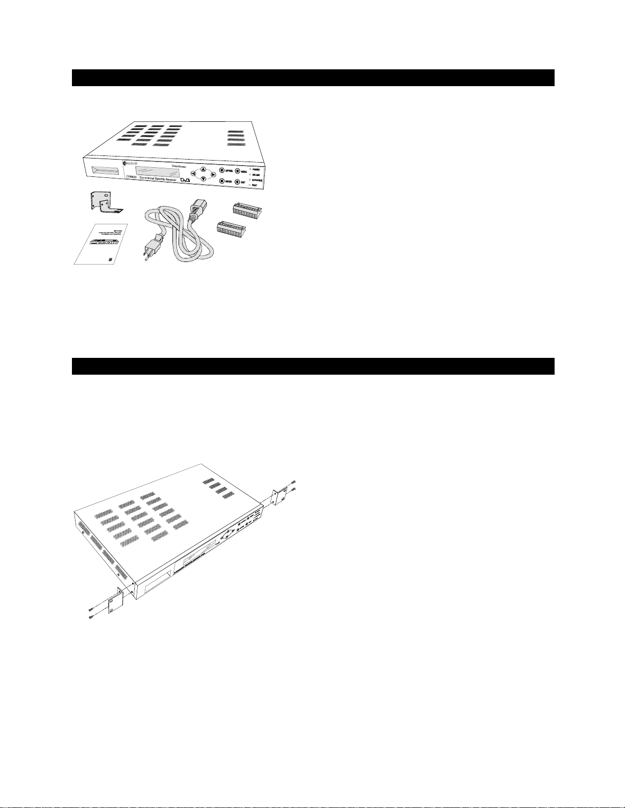
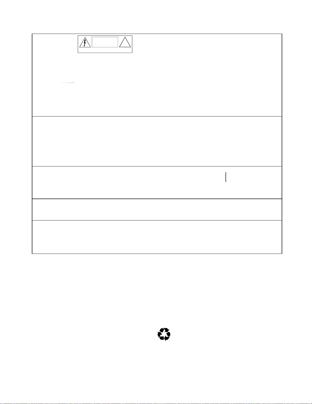
Figure 1: Items shipped with CSR820
Installing the CSR820
Product Contents
Your CSR820 is shipped with the following
items:
2 Rack mounting brackets
2 Plug-in connector blocks (9-pin)
1 US Power cable
1 Installation and Operation Guide
The CSR820 may be installed into a standard
ANSI/EIA RS310-C 19” (48mm) rack (one rack
unit height). Installation includes attaching signal
connections and powering-up the unit.
Figure 2: Rack Mounting
1. Locate the two mounting brackets in the
installation kit.
2. Use the existing mounting screws on the
CSR820 to install the mounting brackets
onto the sides of the IRD.
3. Place the unit in the rack. Mount the
CSR820 to the rack using four screws (not
supplied).
4. If the mounting brackets are attached
properly, they will support the weight of the
CSR820. Leave one RU space above and
below each unit for reliable operation.
2
Page 7

Rear Panel Connections
RELAY 1
COMNOCOMNOCOMNCCOMNCGND
1
2 3 4
9
AUDIO ALARM
R-
GNDR+L-
GNDL+COMNCNO
1
Figure 3: CSR820 Rear Panel
Item Connection Cable Connector
POWER
L-BAND
AUX DATA
OUT
VIDEO OUT
AUDIO
Main AC power input (110-240 VAC). (supplied) IEC-320 C-14
RF input from the LNB.
Connect to the serial port of an auxiliary data device. Twisted pair
Connect to a monitor or video distribution equipment
Connect to speakers or audio distribution equipment
Connect shields to the GND connectors.
Pin Name Description
1 R- Right 2 GND Audi o Ground
3 R+ Right +
4 L- Left 5 GND Audi o Ground
6 L+ Left +
75Ω coax F-type (75Ω)
DB-9 for
22-24 AWG
RS-232
interface
75Ω coax BNC (75Ω)
Shielded
twisted pair
9-pin screw-
type block,
9
ALARM
RELAY
Connect to fault alarm system.
The Alarm Relay states shown on the rear panel are Power Off
and Fault state. When the CSR820 is powered on, the relay
state will change NC to Open and NO to Closed.
• The Alarm Relay cable shield must be connected to one of
the Audio Ground pins (2 or 5).
Caution: Relay maximum input power rating is 24 VDC,
1Amp. Do not exceed the maximum power rating.
Pin Name Description
7 COM Relay Common
8 NC Normally Closed if unpowered or in fault s t ate.
9 NO Normally Open if unpowered or in fault state.
Connect to external equipment. Relay connectors are opened
or closed by external software commands.
• The Relay cable shield must be connected to pin 9.
Caution: Relay maximum input power rating is 24 VDC,
1Amp. Do not exceed the maximum power rating.
Pin Name Description
1 COM Relay 1 Common
2 NO Relay 1 Normal l y Open
3 COM Relay 2 Common
4 NO Relay 2 Normal l y Open
5 COM Relay 3 Common
6 NC Relay 3 Normally Closed
7 COM Relay 4 Common
8 NC Relay 4 Normally Closed.
9 GND Relay 1-4 Shield Ground.
Shielded 9-pin screw-
type block
Shielded 9-pin screw-
type block
3
Page 8

Front Panel
The front panel includes a backlit LCD alphanumeric display, eight push buttons, and four LEDs. The push buttons
allow you to view and control the information that is displayed on the LCD.
CSR820 Commercial Satellite Receiver
Keys Function
MENU
OPTION
ENTER
EXIT
Move to the next main menu screen.
Move to the next screen in a submenu series.
Accept a setting and execute a command.
Leave the current screen and move one level up the menu tree.
Scrolls through setting options or move the cursor to the left.
Scroll through setting options or move the cursor to the right.
Increase a numerical value
Decrease a numerical value
IDEOUARD
TM
VG
Figure 4: CSR820 Front Panel
LEDs Status
POWER
ON LINE
AUTHORIZE
FAULT
Glows green when the CSR820 is ON.
Glows yellow when the CSR820 locks on to an incoming signal.
Glows orange when the CSR820 decrypts the selected program.
Glows red when the CSR820 detects a fault or failure. If FAULT LED
remains lit, contact Tandberg Television Customer Service.
4
Page 9

Menu Structure
Start-Up Screen
Default Screen
MENU
EXIT
ENTER
Logout Screen
Password Login
ENTER
Main Menu
OPTION
Submenu Screens
EXIT
Figure 5: Structure of CSR820 Screens
Menu Screen Format
The CSR820 menu includes a start-up screen,
default screen, password login, main menus, and
submenus.
• On power-up, the CSR820 displays the start-
up screen.
• After completing power-up, the CSR820
displays the default screen, showing the
current service and receiver status.
• The user can enter the IRD menu either in a
login mode or view mode. To login, the user
must enter the correct 4 digit password. To
enter in view mode, the user can scroll past
the password screen and navigate directly into
the menu system.( see page 8, Password
Entry)
Option
Screen name Setting
Viterbi Rate: 1/2
Press ENTER to acquire
Screen
Instruction
Available
Symbol
< > *
Login
Symbol
Figure 6: Menu Screen Format
• The first line shows the name of the screen,
setting value or setting option.
• Some screens display < > Option Available
Symbols in the upper right corner of the
screen which indicates setting options are
Keys are pressed.
available when
or
• Login Symbol will be present if logged into the
menu system.
• The second line displays instructions or status
information about the current parameter.
Menu Operation
1. Press the MENU key to cycle through the five
main menus (Receiver Setup, Service Setup,
IRD Setup, IRD Status, and Pre-Set
Channels).
2. Press OPTION from any main menu screen
to cycle through the submenus.
3. While in any submenu, press
or
to move
between setting options or move the cursor
left or right. Press
or to change setting
values.
4. Press EXIT at any point to move one level up
the menu tree.
5. To log out, press EXIT from any main menu.
At the Logout screen, press
or
to toggle
Yes or No. If you select Yes, press any key to
log out.
6. The CSR820 will automatically log out and
move up to the default screen after 3 minutes,
from last key activity.
5
Page 10

Getting Your IRD authorized
CSR820 can decrypt audio, video, and data
programs encrypted by NDS VideoGuard
conditional access system.
In order to decrypt a program the IRD must be
authorized by the program provider and a correct
Smart Card must be inserted in the IRD smart
card slot located on the front of the IRD.
Entering and changing Password
To operate and change any of the IRD settings,
a correct password must be entered to log into
the IRD menu system. When you have
successfully logged in, an “ * ” will appear on the
top right corner of all the menu screens.
The IRD is delivered with an initial default
password of 0 0
Entering the Password
1. From the Default screen, press MENU. The
Password login screen appears.
2. Enter the factory installed password of 0 0
0 . Press
positions. Press or to change the
values.
0 0.
to move between
or
0
Ensure the Smart Card is fully seated in the IRD.
To get your IRD authorized, contact the program
provider.
3. Press ENTER to accept the password.
4. Verify an * is in the right hand corner of the
menu screen.
Changing the Password
1. The Password can only be changed if you
are operating with the correct password
entered.
2. Press MENU to IRD Setup menu screen.
3. Press OPTION to the New Password
screen.
4. Enter a new password.
6
Page 11

Quick Install and Setup Guide
This section outlines the minimum steps needed
to set up your CSR820.
Before starting the installation, take a moment to
review the front panel and menu operation
(pages 5-6).
• If you will be receiving an encrypted signal, the
CSR820 must be authorized to receive this
signal and an authorized Smart Card must be
inserted. Contact your program provider for
authorization.
• Make sure that the satellite antenna is
properly installed, and the LNB is operational.
Initial Setup
1. Connect the LNB input, audio, video, and
data. Select relay output per the rear panel
connection instructions (page 4).
2. Plug in the power cord. Verify that the
POWER LED is ON.
3. Observe the Self Test Screen and allow the
CSR820 to complete its self test (about 30
seconds). Once the Self Test is successfully
completed, the Default Screen will appear.
Acquire the Signal
1. Press MENU to display the Receiver Setup
menu.
2. Press OPTION to display the Frequency
submenu. Enter the L-Band Frequency.
3. Press OPTION and enter the Symbol Rate.
4. Press OPTION and enter the Viterbi Rate.
5. Press OPTION and enter the LNB Polarity.
6. Press OPTION and enter the Satellite Band.
7. Press OPTION and set the LNB On or Off.
8. Press ENTER to acquire the signal.
9. Verify that the ON LINE LED is lit.
Select a Video Mode (NTSC or PAL)
1. Press MENU to display the IRD Setup menu.
2. Select a Video Mode. The selected mode
should be the same as the transmitted video
format.
3. Allow 30 seconds for the CSR820 to reboot.
4. If the FAULT LED remains lit, contact
Tandberg Television Customer Service.
5. Press MENU to display the Password screen.
6. Enter the default password or your own
password.
7. Press ENTER to accept the password.
Select a Service
1. Press MENU to display the Service Setup
menu.
2. Select a Service from the ones that are
displayed.
3. Select a Video channel.
4. Select an Audio channel.
5. Verify that audio and video are present.
7
Page 12

Self Test
in progress
Wait...
Service PROGRAM 1
Receiver: Idle
MENU
0
Enter 4 digit Password
MENU
Receiver Setup
Press OPTION
OPTION
Frequency:
1070.00 MHz
Press ENTER to acquire
OPTION
Symbol Rate:
13.3330 MS
Press ENTER to acquire
OPTION
Viterbi Rate:
3/4
Press ENTER to acquire
OPTION
Acquisn Bw:
00004 MHz
Press ENTER to acquire
OPTION
LNB Polarity:
Horz
Press ENTER to acquire
OPTION
Satellite Band:
Ku-High
Press ENTER to acquire
OPTION
LNB Offset:
00000
MHz
Press ENTER to acquire
OPTION
Receiver Mode:
Normal
Press ENTER to acquire
OPTION
LNB Voltage:
ON
Press ENTER to acquire
Menu Tree Menu Tr ee
CSR820 Menu System
This diagram includes all of the menus and submenus in the
CSR820 menu system.
Arrows indicate the order of submenus within each main menu. Press
OPTION or MENU as indicated.
Items that you may enter are shown in
Default entries are shown on each screen. Ranges or options for each menu
are shown in italics.
Note boxes provide additional information about the menus.
If you enter a Password, an * symbol will appear in the upper right corner
of each screen.
Enter a password if you want to
make changes and * appears on
upper R/H corner.
Press MENU if you want to view
settings only.
MENU
950-2150 MHz
1-45 Ms/sec.
1/2,2/3,3/4,5/6,7/8
Default = 4MHz
Vert/Horz
C, Ku-Low,
Ku-High, User
Only available if you
select User in the
previous menu
Normal/Install
Signal Quality: 0000
Press any key to exit
Receiver Setup Notes
On/Off
All of the receiver settings must be entered properly in order to
acquire the signal.
OPTION
If the acquisition fails, RECEIVER NOT ACQUIRED will
display for 2 seconds, and the receiver will return to the
display where the acquisition was initiated.
If any entries are out of the valid range, the receiver will
display an INVALID ENTRY message.
Service Setup Notes
Video, Audio, and Teletext screen will only be
displayed if that service is available on the incoming
data stream.
If Service name is not transmitted, UNNAMED is
displayed.
bold
Service Setup
Press OPTION
Service:
Press ENTER to activate
Select Video
1
Video
Select Audio
1
Audio
Select Teletext
OFF
Select AuxData
ON
Signal Quality appears if the
receiver is in Install mode.
type.
OPTION
PROGRAM 1
OPTION
OPTION
OPTION
OPTION
OPTION
< >
MENU
Select
Service
Default is 1
Default is 1
On or Off
(PAL only)
On or Off
8
Page 13

Menu Tree
IRD Setup
Press OPTION
MENU
Video Mode:
Press ENTER to update
Volume: < >
| | | | | | | | | | | |
Audio Mode: < >
Normal
LCD Brightness < >
| | | | | | | | | | | |
A/V Output Test < >
Off
Closed Caption < >
ON
New Password:
Press ENTER to Start
AMOL:
OFF
Press ENTER to update
Reset Factory Defaults
Press ENTER to update
OPTION
NTSC M
OPTION
OPTION
OPTION
OPTION
OPTION
OPTION
OPTION
OPTION
< >
< >
To Receiver Setup
MENU
PAL B, D, G, H, I, M, N
NTSC-M
Default is set at
maximum
Dual L, Normal,
Dual R
Default is set at
maximum
Output color bars and
a 4-second 1 KHz tone to
both audio channels
Default is ON
(NTSC only)
ON/OFF
(NTSC only)
OPTION
IRD Status
Press OPTION
OPTION
Boot version: 1.9.9
NIM version: X1.9.9
OPTION
Softwar version: 1.01
Verifier version: 23000
OPTION
Recv state: Idle
Recv status: Not Locked
OPTION
Eb/No: 0000 dB
OPTION
Estimated BER:
0
OPTION
Packet Error Rate:
0
OPTION
CA Status:
Not Authorized
OPTION
ID: 000001FD92B00280
MENU
Pre-Set Channels
Press OPTION
OPTION
Memory Not Set 1
(Scrolls Between 1 & 12)
OPTION
Press OPTION to view other
Services.
Status may be Install, Tracking,
Acquiring, Idle, Power Up,
Scanning, Unknown
Eb/No appears if the receiver
has aquired a signal
Authorized,
Not Authorized
OPTION
IRD Setup Notes
Video Mode
The system will reboot after you change the Video Mode selection. Video mode selected should match both video format
received and video format of monitor.
Audio Modes
Normal - If the audio input is stereo, the two audio channels (left and right) are output to the audio output connectors.
Dual Right - Right channel audio is selected for both audio output connectors.
Dual Left - Left channel audio is selected for both audio output connectors.
eset Factory Defaults
R
This feature will reset all settings to the factory default settings shown on this page. The system will reboot after you reset the
defaults.
9
Page 14

IRD User Helpful Hints
Frequency
Enter the IRD input frequency as accurate as is known.
If the exact frequency is not known, the entered
frequency should be accurate within the selected
acquisition Bandwidth. Valid values, 950 MHz to 2150
MHz.
Symbol Rate
Enter the symbol rate being received.
Viterbi Rate
Select the code rate being received.
Acquisition Bandwidth
The default acquisition bandwidth is 4MHz. The
acquisition bandwidth is used to limit or expand the
receiver scanning range.
The user can select the desired acquisition bandwidth
to help find the desired signal. If the user is uncertain
of the exact IRD input frequency to receive, increase
the bandwidth to increase the receiver scanning range.
If multiple signals are close to each other, limit the
bandwidth to limit the receiver scanning range.
The receiver will scan the width of the acquisition
bandwidth from the entered IRD input frequency.
LNB Polarity
LNB Polarity option changes the LNB voltage that is
supplied on the LNB input connector.
When Vertical polarity is selected, the LNB voltage is
approximately 13VDC. When Horizontal polarity is
selected, the LNB voltage is approximately 17VDC.
Satellite Band
The Satellite Band option is used by the IRD to enter
the LNB Local Oscillator (LO) frequency. This
frequency is used by the IRD to determine the
frequency of the channels in the transmission at the
input to the IRD.
The IRD is programmed with the following LO
frequencies for the given bands.
1. C Band: 5.15 GHz
2. Ku Low Band 9.75 GHz
3. Ku High Band 10.6 GHz
• Selecting Ku High will also output a 22KHz signal
on the input connector to select the Ku High LO in
the LNB. This band is also the default condition.
If other than the above LO frequencies are being used
by the LNB, the User option can be selected to enter
the custom LO frequency.
The IRD must have the correct settings to lock onto the
initial signal (home channel). The following are
required: LO frequency or Band, IRD input frequency,
LNB polarity, Symbol rate and Viterbi rate. Once the
home channel is found, the Network Information Table
10
(NIT) in the data stream supplies further information if
available. The NIT Satellite Delivery system descriptor
frequency is the frequency on which the satellite
transmits the multiplex (Transponder Frequency).
The formula to calculate the IRD input frequency is
based on the NIT satellite delivery descriptor frequency
(Transponder Frequency) and the Local Oscillator (LO)
frequency:
IRD input frequency = Transponder Frequency -
LO Frequency (GHz)
For C Band only, use the Eq.:
IRD input frequency = LO Frequency (GHz) -
Transponder Frequency
Note: LO may be User Defined or one of the standard
bands selected by the operator.
Example: Suppose that the Transponder Frequency is
12.3 GHz, and Ku-High is set. From the table, Ku-High
has an LO frequency of 10.6 GHz. The NIT frequency
descriptor would be 012.30000.
IRD Input Frequency = (12.3 - 10.6 ) GHz = 1.7 GHz
The IRD will tune to 1.7 GHz.
Receiver Mode
Receiver Mode selection allows the user to see the
relative signal strength form the LNB. This feature can
be used to sight the dish antenna to a desired satellite.
Normal setting is selected to use the IRD as a receiver
decoder. Install setting is selected to view the signal
level. If Install is selected, the IRD will stop receiving
and decoding functions, thus no video, audio, or data
will be outputted.
LNB Voltage
LNB Voltage on or off selection allows the user to turn
off the LNB voltage when multiple CSR820s are
connected to one LNB or when the IRD does not need
to provide the LNB power. This feature negates the
need to use DC block in the network.
Service Selection
The service name will only appear if the service name
is available in the SDT table in the signal.
Select Video
All the video programs available in the selected service
will be displayed. This feature allows the user to select
the desired video program within the selected service.
Select Audio
All the audio programs available in the selected service
will be displayed. This feature allows the user to select
the desired audio program within the selected service.
Select Teletext
Select Teletext screen will only appear when the video
mode has been selected to PAL. This feature allows
the user to turn on or off the teletext being received.
Page 15

Video Mode
Video Mode options allows the user to select the
correct Video Format. The video mode selected must
match the video format being received for the IRD to
display the video correctly. When video selection is
made, the IRD will reboot then output the video in the
correct video format.
Audio Mode
Audio Mode option allows the user to direct one of the
channels to both IRD audio connectors.
Closed Caption
Closed Caption screen will only appear when the Video
Mode has been selected to NTSC. Closed caption can
be selected on or off.
Reset Factory Default
Reset Factory Default feature allows the user to
change all the IRD settings to the default settings. The
default settings are shown in the Menu Tree diagram.
Boot Version
Boot Version displays the version number of the IRD’s
boot software. The version number will change if the
boot software is changed through over-the-air
download.
NIM Version
NIM Version displays the version number of the IRD’s
Network Interface Module (QPSK Receiver) software.
The version number will change when the NIM software
is changed through over-the-air download.
Software Version
Software Version displays the version number of the
IRD’s top level software. The version number will
change if the software is changed through over-the-air
download.
Verifier Version
Verifier Version displays the version number of the
IRD’s conditional access (Verifier) software. The
version number will change if the Verifier software is
changed through over-the-air down load.
Eb/No (Energy over Noise)
Eb/No display will only appear when the IRD has
successfully received a signal. It is desirable to have a
high signal to noise ratio.
BER (Bit Error Rate)
BER reading provides information on bit error rate.
Packet Error Rate
Packet Error Rate provides information on packet error
rate.
ID Number
The ID number displayed is the IRD ID number. This
number can be used to identify the IRD when getting
the IRD authorized.
Pre-Set Channel
The Pre-Set Channel screen is used to tune the
CSR820 to a pre-set channel from the service
provider’s transport stream.
The CSR820 stores 12 pre-set channels. Channel 11 is
reserved for Power Up. Channel 12 is the Emergency
Home channel.
The Pre-Set Channels screen allows the operator to
tune to any of the Pre-Set Channels, but does not allow
any change to any of the channel settings.
To clear all items in the Pre-Set Channels memory,
reset the factory defaults.
If the Power-Up channel is not available the CSR820
will display “Memory Not Set 11” and the IRD will tune
to the last channel prior to power down.
Customer Service Information
If you have problems installing or operating the unit
after you have carefully followed the instructions in this
manual, contact Tandberg Television Customer Service
for assistance or service.
Confirmed defective units should be returned to the
Tandberg Television repair center. Return authorization
may be required, and return instructions can be
obtained by contacting Tandberg Television.
Customer Service Telephone Numbers
Be sure to write down the Serial Number of your
CSR820 (located on the rear panel) before calling
Tandberg Television Customer Service.
11
You may contact customer service at one of the
following numbers:
1-888-637-0023 (United States only)
or
(949) 725-2699
Tandberg Television
Customer Service Department
25901 Commercentre Drive
Lake Forest, CA 92630 USA
Page 16

Specifications
Power Input
Input Voltage 100 – 240 VAC S i ngl e-phase
Line Frequency 50 – 60 Hz
Power Consumption 35 W max.
RF Input
Connector F-type connect or, 75 ohm
Input Waveform Shaped QPSK at variable symbol rates of 1 to 45 Msps
RF Input Frequency Range 950 – 2150 MHz
RF Input Power Levels -65 to -25 dBm
Analog Audio Output
Connector 9-pin screw-type connec tor on the back panel.
Audio Output 1 stereo or 2 monaural channels
Signal-to-Noise Ratio > 54 dB uni fied weighted
Dynamic Range > 20Hz - 15 kHz
Gain-Frequency Response ± 0.5 dB p-p, 20 Hz – 20kHz
Total Harmonic Distortion Plus
Noise
Output Level Range -4 dBm t o +18 dB m into 600Ω balanced
Analog Video Output
Connector 75Ω BNC connector on the back panel
Video Output Compos i te video
Frequency Response ± 1.5 dB at 1kHz to 5 MHz
Video Level 1V p-p ± 2.5%
Signal-to-Noise Ratio 60 dB unified weighted
Luminance Nonlinearity < 4%
Differential Gain ± 2%
Differential Phase ± .5º
Chrominance-Luminance 37.5 nS max.
Relay Contact Rating
LNB Power Supply
Vertical Polarization 11.5-14 V
Horizontal Polarization 16-19 V
Auxiliary Data Output
Connector DB-9/RS232 connec tor on the back panel
Baud Rate 19.2 kbps max.
Format Asynchronous, 8 data bits, no parity, 1 stop bit
Environmental Operating Restrictions
Operating Temperature Range
(ambient)
Maximum Humidity 95% non-condensing
Maximum Altitude 4500 meters (14,864 ft)
Physical
Dimensions (W x H x D) 4.5 mm x 47.3 mm x 39 mm (1 3/4” x 18 5/8” x 15 3/8”)
Weight 3.6 kg (8 lbs. )
< 0.5% at 1 kHz
24 VDC, 1 Amp
0 °C to +50 °C
(32 °F to 122 °F)
12
Page 17

Warranty
Tandberg Television warrants that Products delivered
hereunder shall be free from defec t s in material and
workmanship under normal use and s ervi ce for a period of
twelve (12) months from t he del i very of Products to Buyer.
If, during such twelve month period:
(i) Tandberg Televisi on i s notified promptly in writing upon
discovery of any defect in t he Products, including a
detailed description of s uch defect;
(ii) such Products are returned to Tandberg Tel evi sion,
F.O.B. Tandberg Television’s facility;
(iii) any s uch return is authorized by the release by
Tandberg Television of a Return Material Authori zat i on
(RMA) and the RMA number issued Tandberg
Television is clearly marked on all accompanying
documentation; and
(iv) Tandberg Television’s examination of such Products
discloses to Tandberg Televis i on’ s satisfaction t hat
such Products are defec tive and such defects are not
caused by accident, abuse, misuse, neglect, alteration,
improper installati on, repai r or al teration by someone
other than Tandberg Television, im proper t esting, or
use contrary to any instruc t i ons issued by Tandberg
Television, then within a reasonable ti me Tandberg
Television shall (at its sole option) either repair, replace
or credit the Buyer for such products. Tandberg
Television shall return any Produc t s repaired or
replaced under this warranty to the Buyer,
transportation prepaid. The performance of this
warranty does not extend the warranty period of any
Products beyond that period applicable to the Products
originally delivered.
• This warranty does not cover charges for any
assembly, inst al l ation, setup or removal, or
adjustment of controls.
• This warranty shall be void if any product marking
or label has been altered, defaced, or removed, or
if any component has been alt ered, modified,
used improperly, or had its housing opened.
• The foregoing warranty shall not cover any
damage or defect that is caused by accident,
abuse, misuse, negl ect, alteration, improper
installation, set up, removal, maintenanc e,
shipment, repair, or alteration by someone other
than Tandberg Television, improper t esting or use
contrary to any instructi ons issued by Tandberg
Television, damages or inoperability caused by
assembly or use with incompatible products, or
reception problems caused by inadequate
antenna systems.
• The foregoing warranty constitut es Tandberg
Television’s exclusive liability, and the exclusive
remedy of buyer, for any breach of any warranty or
other nonconformity of produc ts. This warranty is
exclusive, and in lieu of all other warranties,
express, implied, or st atutory, including but not
limited to the warranties of merchant abilit y and
fitness for a partic ul ar purpose, which are hereby
expressly disclaimed. There are no warranties that
extend beyond the description of this l i mited
warranty.
• For breach of any written or impli ed warranty with
respect to the product, i n no event shall Tandberg
Television be liable, in cont ract or in tort or under any
other legal theory, for incident al , indirect, special or
consequential damages i ncurred or sustained by you or
by others, regardless of whether Tandberg Televis i on
was informed about the possibility of s uch damages,
and in no event shall Tandberg Television’s t otal
liability exceed an amount equal to the consideration
paid for the products.
How to Obtain Warranty Service
To obtain warranty service, you mus t:
1. Call or write Tandberg Television Americ as, Inc.
Customer Service within the applicable warranty period
to obtain a Return Material Authorizati on (RMA )
number at:
Tandberg Television Americas, Inc.
Customer Service Department
25901 Commercentre Drive
Lake Forest, CA 92630 USA
Telephone: 1-888-637-0023
or (949) 725-2699
When you call or write, as k for the address to send the
product, if the product i s to be returned. Do not return
the unit to the above address unless instructed to do
so.
2. If the Tandberg Television Customer Service
Department requests t hat you return the product, pack
it safely and securely, pref erabl y i n the original shipping
carton. Enclose a let t er explaining the problem. Be sure
to enclose a copy of your sales receipt or other proof of
purchase date and include the Return Materi al
Authorization (RMA) number, your name, address, and
phone number. Ship it insured to the authorized service
center address specifi ed by Tandberg Tel evi sion. All
packing, shipping, and ins u rance charges to return the
component to Tandberg Television must be prepaid by
you. A qualified technician will be required to remove or
install a product, and any out-of- warranty charges for
such work are your responsibility.
User Notes:
13
Page 18

User Notes:
14
Page 19

15
Page 20

Tandberg Television
25901 Commercentre Drive
Lake Forest, CA 92630 USA
(888) 637-0023 (United States only)
(949) 725-2699
 Loading...