

Page 1
User Manual
Software version F4
This document is not to be reproduced in whole or in part without permission in writing from:
D13865-01
Page 2

TANDBERG COMPASS MXP / UTILITY MXP
Trademarks and Copyright
All rights reserved. This document contains information that is proprietary to TANDBERG. No part
of this publication may be reproduced, stored in a retrieval system, or transmitted, in any form, or
by any means, electronically, mechanically, by photocopying, or otherwise, without the prior
written permission of TANDBERG. Nationally and internationally recognized trademarks and
trade names are the property of their respective holders and are hereby acknowledged.
This product includes software developed by the OpenSSL Project for use in the OpenSSL
Toolkit. Copyright © 1998-2002 The OpenSSL Project. All rights reserved.
This product includes cryptographic software written by Eric Young. Copyright © 1995-1998 Eric
Young. All rights reserved.
Contains iType™ from Agfa Monotype Corporation.
ICU License - ICU 1.8.1 and later COPYRIGHT AND PERMISSION NOTICE Copyright (c) 1995-
2003 International Business Machines Corporation and others All rights reserved.
Disclaimer
The information in this document is furnished for informational purposes only, is subject to
change without prior notice, and should not be construed as a commitment by TANDBERG. The
information in this document is believed to be accurate and reliable; however TANDBERG
assumes no responsibility or liability for any errors or inaccuracies that may appear in this
document, nor for any infringements of patents or other rights of third parties resulting from its
use. No license is granted under any patents or patent rights of TANDBERG.
This document was written by the Research and Development Department of TANDBERG,
Norway. We are committed to maintain a high level of quality in all our documentation. Towards
this effort, we welcome you to Contact us with comments and suggestions regarding the content
and structure of this document.
COPYRIGHT © 2006, TANDBERG
ii
Page 3

Environmental Issues
TANDBERG visual communication products significantly reduce the need for travel and thereby
help reduce various types of pollution. TANDBERG recommends the use of low energy
peripherals, such as EnergyStar™ monitors. Thank you for buying a TANDBERG product.
Battery handling
The batteries for the Remote Control are Long Life Alkaline batteries, which means you will need
fewer batteries, further benefiting the environment. Please follow the guidelines on the packing
material for handling and disposal instructions for the batteries.
Waste handling
This TANDBERG product contains no consumables that require disposal. You should retain the
packaging materials in case future shipment is necessary. Please contact your local authorities
for information on waste handling and recycling regulations for electronic products.
Production of products
Our factories employ the most efficient environmental methods for reducing waste and pollution.
Our designers do their best to ensure TANDBERG products are highly recyclable.
Digital User Manuals
TANDBERG is pleased to announce that it has replaced the printed versions of its User Manuals
with a digital CD version. Instead of a range of different user manuals, there is now one CD which
can be used with all TANDBERG MXP products. The CD contains a variety of supported
languages. The environmental benefits of digital manuals are significant, from saving paper, to
reduced weight for shipping. Even the CD itself is recyclable. Not only are they more ecological,
digital manuals are more user friendly. A simple web-based search feature helps users directly
access the information they need. In addition, this TANDBERG video system now has an intuitive
on-screen help function, which provides a range of useful features and tips. If desired, the user
manuals on the CD can still be printed locally.
iii
Page 4

TANDBERG COMPASS MXP / UTILITY MXP
Operator Safety Summary
For your protection, please read these safety instructions completely before operating the
equipment and keep this manual for future reference. The information in this summary is intended
for operators. Carefully observe all warnings, precautions and instructions both on the apparatus
and in the operating instructions.
Warnings
Water and moisture - Do not operate the equipment under or near water - for example
near a bathtub, kitchen sink, or laundry tub, in a wet basement, or near a swimming pool
or in areas with high humidity.
Cleaning - Unplug the apparatus from the wall outlet before cleaning or polishing. Do not
use liquid cleaners or aerosol cleaners. Use a lint-free cloth lightly moistened with water
for cleaning the exterior of the apparatus.
Ventilation - Do not block any of the ventilation openings of the apparatus. Install in
accordance with the installation instructions. Never cover the slots and openings with a
cloth or other material. Never install the apparatus near heat sources such as radiators,
heat registers, stoves, or other apparatus (including amplifiers) that produce heat.
Grounding or Polarization - Do not defeat the safety purpose of the polarized or
grounding-type plug. A polarized plug has two blades with one wider than the other. A
grounding type plug has two blades and a third grounding prong. The wide blade or third
prong is provided for your safety. If the provided plug does not fit into your outlet, consult
an electrician.
Power-Cord Protection - Route the power cord so as to avoid it being walked on or
pinched by items placed upon or against it, paying particular attention to the plugs,
receptacles, and the point where the cord exits from the apparatus.
Attachments - Only use attachments as recommended by the manufacturer.
Accessories - Most systems should only be used with a cart, stand, tripod, bracket, or
table specified by the manufacturer, or sold with the apparatus. When a cart is used, use
caution when moving the cart/apparatus combination to avoid injury from tip-over.
Lightning - Unplug this apparatus during lightning storms or when unused for long periods
of time.
ISDN cables - CAUTION - To reduce the risk of fire, use only No. 26 AWG or larger
telecommunication line cord.
Servicing - Do not attempt to service the apparatus yourself as opening or removing
covers may expose you to dangerous voltages or other hazards, and will void the
warranty. Refer all servicing to qualified service personnel.
Damaged Equipment - Unplug the apparatus from the outlet and refer servicing to
qualified personnel under the following conditions:
When the power cord or plug is damaged or frayed
If liquid has been spilled or objects have fallen into the apparatus
If the apparatus has been exposed to rain or moisture
If the apparatus has been subjected to excessive shock by being dropped, or the
cabinet has been damaged
If the apparatus fails to operate in accordance with the operating instructions
iv
Page 5

Contact us
If you have any questions, comments or suggestions, please see the Online Support service at
www.tandberg.net.
It is also possible to send a fax or mail to the attention of:
Product and Sales Support
TANDBERG
P.O. Box 92
1325 Lysaker
Norway
Tel: +47 67 125 125
Fax: +47 67 125 234
v
Page 6

TANDBERG COMPASS MXP / UTILITY MXP
Table of Contents
1 Introduction............................................................................................................................... 1
1.1 At a Glance ............................................................................................................................ 3
1.2 Menu Structure ...................................................................................................................... 5
2 Installation ................................................................................................................................ 8
2.1 Unpacking.............................................................................................................................. 9
2.2 Connecting Cables............................................................................................................... 10
2.3 Monitor Configuration........................................................................................................... 11
2.4 System Configuration........................................................................................................... 12
3 General Use ........................................................................................................................... 15
3.1 The Welcome Screen (Normal Mode)................................................................................. 16
3.2 The Welcome Screen (Kiosk Mode) .................................................................................... 17
3.3 Using the Remote Control.................................................................................................... 19
3.3.1 Navigation................................................................................................................ 21
3.3.2 Number and Letter keys........................................................................................... 22
3.4 On-screen Indicators............................................................................................................ 23
3.5 Using the Kiosk Menu..........................................................................................................24
3.6 Using the Language Menu................................................................................................... 25
3.7 Place a Call.......................................................................................................................... 26
3.8 Receive a Call...................................................................................................................... 27
3.9 End Call................................................................................................................................ 28
3.10 Using the Handset ............................................................................................................. 29
3.11 Standby.............................................................................................................................. 31
3.12 Phone Book - My Contacts ................................................................................................ 32
3.12.1 Add New Contact..................................................................................................... 33
3.12.2 Edit Contact ............................................................................................................. 34
3.12.3 Delete Contact ......................................................................................................... 35
3.12.4 Copy Contact to My Contacts.................................................................................. 36
3.13 Camera Control.................................................................................................................. 37
3.14 Dual Stream (DuoVideoTF/H.239)..................................................................................... 38
3.15 Control Panel ..................................................................................................................... 39
3.16 Diagnostics......................................................................................................................... 40
3.16.1 System Information.................................................................................................. 41
3.16.2 Channel Status ........................................................................................................ 42
3.16.3 Call Status................................................................................................................ 43
3.16.4 System Selftest........................................................................................................ 44
3.16.5 View Administrator Settings..................................................................................... 45
3.16.6 IP Address Conflict Check....................................................................................... 49
3.16.7 Warnings..................................................................................................................50
3.16.8 Text Chat ................................................................................................................. 52
3.16.9 Administrator Settings..............................................................................................53
3.16.10 Restart.................................................................................................................54
3.16.11 User Guide .......................................................................................................... 55
4 Administrator Settings ............................................................................................................ 56
4.1 General Settings .................................................................................................................. 57
4.1.1 Language................................................................................................................. 58
4.1.2 System Name .......................................................................................................... 59
4.1.3 International Name................................................................................................... 60
4.1.4 Auto Answer............................................................................................................. 61
4.1.5 Phone Book Settings ............................................................................................... 62
4.1.6 External Services Settings....................................................................................... 63
4.1.7 Permissions ............................................................................................................. 64
vi
Page 7

4.1.8 Screen Settings........................................................................................................ 66
4.1.9 Software Options ..................................................................................................... 71
4.1.10 Date and Time Settings ........................................................................................... 72
4.1.11 Max Call Length....................................................................................................... 73
4.2 Menu Settings......................................................................................................................74
4.2.1 Input Editor Language.............................................................................................. 75
4.2.2 Menu Timeout In Call...............................................................................................76
4.2.3 Balloon Help............................................................................................................. 77
4.2.4 Administrator Password........................................................................................... 78
4.2.5 Kiosk Mode Settings................................................................................................ 79
4.2.6 Startup ..................................................................................................................... 82
4.2.7 Icons......................................................................................................................... 84
4.3 Presentation Settings........................................................................................................... 85
4.3.1 Presentation Start .................................................................................................... 86
4.3.2 H.239........................................................................................................................ 87
4.3.3 Startup Video Source...............................................................................................88
4.3.4 Presentation Source ................................................................................................ 89
4.3.5 Snapshot Source ..................................................................................................... 90
4.3.6 Auto-Display Snapshot ............................................................................................ 91
4.3.7 PIP Appearance.......................................................................................................92
4.3.8 PIP Placing .............................................................................................................. 93
4.3.9 VNC Settings ........................................................................................................... 94
4.4 Call Quality........................................................................................................................... 95
4.4.1 Video Algorithm........................................................................................................ 96
4.4.2 Audio Algorithm........................................................................................................ 97
4.4.3 Natural Video ........................................................................................................... 98
4.4.4 Max Upstream Rate (kbps)...................................................................................... 99
4.4.5 Video Quality.......................................................................................................... 100
4.4.6 Default Call Settings .............................................................................................. 103
4.5 Audio.................................................................................................................................. 106
4.5.1 Headset Level Settings.......................................................................................... 107
4.5.2 Alert Tones and Volume ........................................................................................ 108
4.6 Video.................................................................................................................................. 109
4.6.1 MCU Status Line....................................................................................................110
4.6.2 Web Snapshots...................................................................................................... 111
4.6.3 Video Name ........................................................................................................... 112
4.7 Security.............................................................................................................................. 113
4.7.1 Encryption.............................................................................................................. 114
4.7.2 Encryption Mode.................................................................................................... 115
4.7.3 Passwords ............................................................................................................. 116
4.8 Network.............................................................................................................................. 117
4.8.1 ISDN-BRI Settings ................................................................................................. 118
4.8.2 LAN Settings.......................................................................................................... 120
4.8.3 Network Profiles.....................................................................................................139
4.8.4 Restore Default Settings........................................................................................ 140
5 Interfaces.............................................................................................................................. 141
5.1.1 Video......................................................................................................................142
5.1.2 Audio......................................................................................................................144
5.1.3 Network..................................................................................................................145
6 Appendices........................................................................................................................... 146
7 Glossary ............................................................................................................................... 172
vii
Page 8

TANDBERG COMPASS MXP / UTILITY MXP
viii
Page 9

1 Introduction
1 Introduction
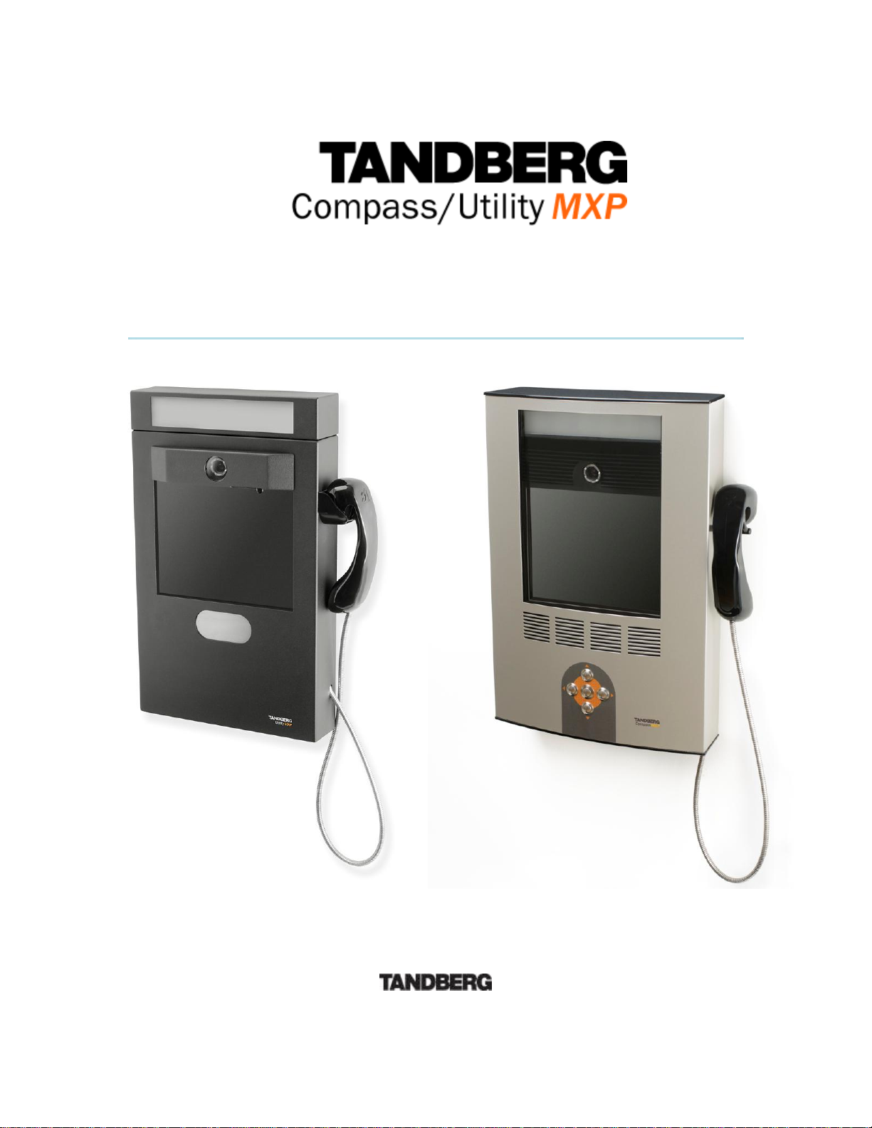
The TANDBERG Compass MXP provides essential video features for face to face
communication in public areas with the quality and reliability found in all TANDBERG equipment.
The TANDBERG Utility MXP provides essential video features for face to face communication in
rugged environments with the quality and reliability found in all TANDBERG equipment.
Audio Quality
High-performance audio provides a richer, more complete visual communication experience. The
MPEG4 AAC-LD standard is used to provide true standards-based CD-quality, stereo audio.
NEW Eliminate disturbance from GSM mobile phones and Blackberry devices
Video Quality
Features which ensure high quality video includes:
Natural VideoTF which provides a 60 fields per second true interlaced picture.
H.264 video compression up to 768kbps.
NEW High quality video and native 16:9 formats
Network
The system supports videoconferencing via both IP and ISDN networks. The bandwidth
capabilities are:
up to 768kbps on IP
up to 384*kbps on ISDN
SIP support
If channels are dropped during a videoconferencing session, downspeedingTF automatically
maintains connections without interruption.
Security
Secure ConferenceTF provides embedded encryption for Point-to-Point calls and ensures both
privacy and security.
The system is delivered with integrated Expressway™ firewall traversal technology. When used
together with a TANDBERG Border Controller it enables:
Secure and seamless traversal of ANY firewall.
No missing features when traversing the firewall – works with H.264, MPEG4 audio,
encryption.
Outside systems, such as home offices, to be part of the enterprise dial plan.
1
Page 10

TANDBERG COMPASS MXP / UTILITY MXP
NEW H.460, ITU Standardized firewall traversal, support
NEW High security network authentication (802.1x)
The TANDBERG videoconferencing system can also be used purely as an audio-bridge (with an
ISDN connection).
Presentations
The Natural Presenter Package (NPP), makes it possible to receive presentations and comprises:
Digital ClarityTF which provides presentations of exceptionally high quality resolution video.
Users can display video and presentations in the best layout based on the situation. Supported
screen layouts are:
Picture in Picture
Picture outside Picture
Side by Side
User interfaces
A web-interface to the codec provides:
System management, diagnostics and software uploads.
Text chat/closed captioning.
Unicast Streaming – which allows broadcasting of audio/video via an IP network to a
single compatible client (RealMedia™ or Apple Quicktime™) or streaming server.
The On-Screen Menu:
Easy interface for first-time users with symbols and descriptions
Builds upon the familiar current interface
NEW Enhanced language support with Asian and non-Latin character text input in the
menu for local language system names
NEW Simplified on-screen menu, Kiosk Mode, designed for public environments.
Interoperability
The TANDBERG Compass MXP and Utility MXP are worldwide compatible with other standardsbased videoconferencing systems.
* - optional feature. To check which options are installed, select Control Panel - Diagnostics - System Information in the
menu.
TF
- TANDBERG First
2
Page 11
Utility MXP
Compass MXP
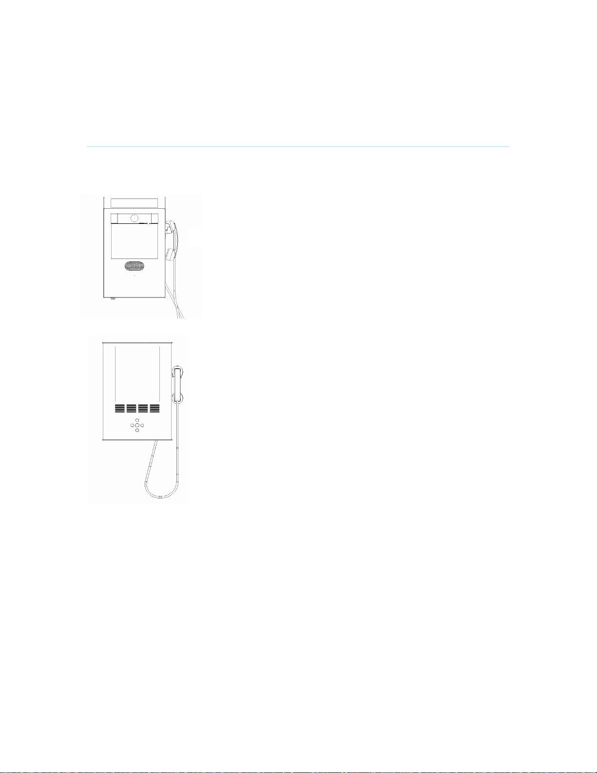
1.1 At a Glance
1 Introduction
Camera
The camera is an integrated part of the unit
and is centrally placed just above the
monitor. On the Utility MXP it is possible to
close the camera (for privacy) by sliding
across a door.
Monitor
The Digital LCD displays the far-end
videoconferencing site in addition to the
menu.
Codec
The codec is the heart of the system. Its main
task is the compression of outgoing video,
audio and data, the transmission of this
information to the far end and the
decompression of the incoming information the name codec comes from a combination of
the two words compression and
decompression.
Figure 1-1. TANDBERG Utility MXP and Compass MXP
Microphone
The microphone is integrated and located at the edge on the left hand side of the unit.
Handset
For privacy, both Utility MXP and Compass MXP are delivered with a handset located on the right
hand side of the unit. Lifting the handset from the cradle automatically toggles between internal
microphone/loudspeaker and the handset.
Lamp
A LED (light emitting diode) lamp is integrated into the top of the unit and gives optimally directed
additional illumination to the users face. This improves the quality of the image transmitted to the
3
Page 12

TANDBERG COMPASS MXP / UTILITY MXP
far end. The power output of the lamp can be varied upon installation (or by service personnel
thereafter), and can be adjusted from zero to full power.
Remote Control
The remote control is only delivered with the TANDBERG Utility MXP.
The remote control is located inside the locked cabinet on the Utility MXP, and is intended for
system setup when using ISDN. The reception of the remote control signal is limited to a small
hole directly under the speaker mesh on the Utility MXP.
The remote control is used to control all functions of the system. The remote control uses 4 AAA
batteries. The system will tell you when batteries are running low. Change the batteries at the
back of the remote control.
The reach of the remote control signal is around 20 meters. For users sitting in an open plan
office, this can cause problems. Use the little, white switch placed under the batteries to change
the reach of the signal from 20 meters to 2 meters. This will prevent you from unintentionally
controlling another video system, when you control your own system.
4
Page 13
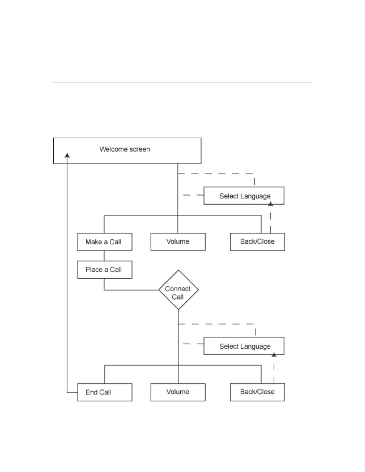
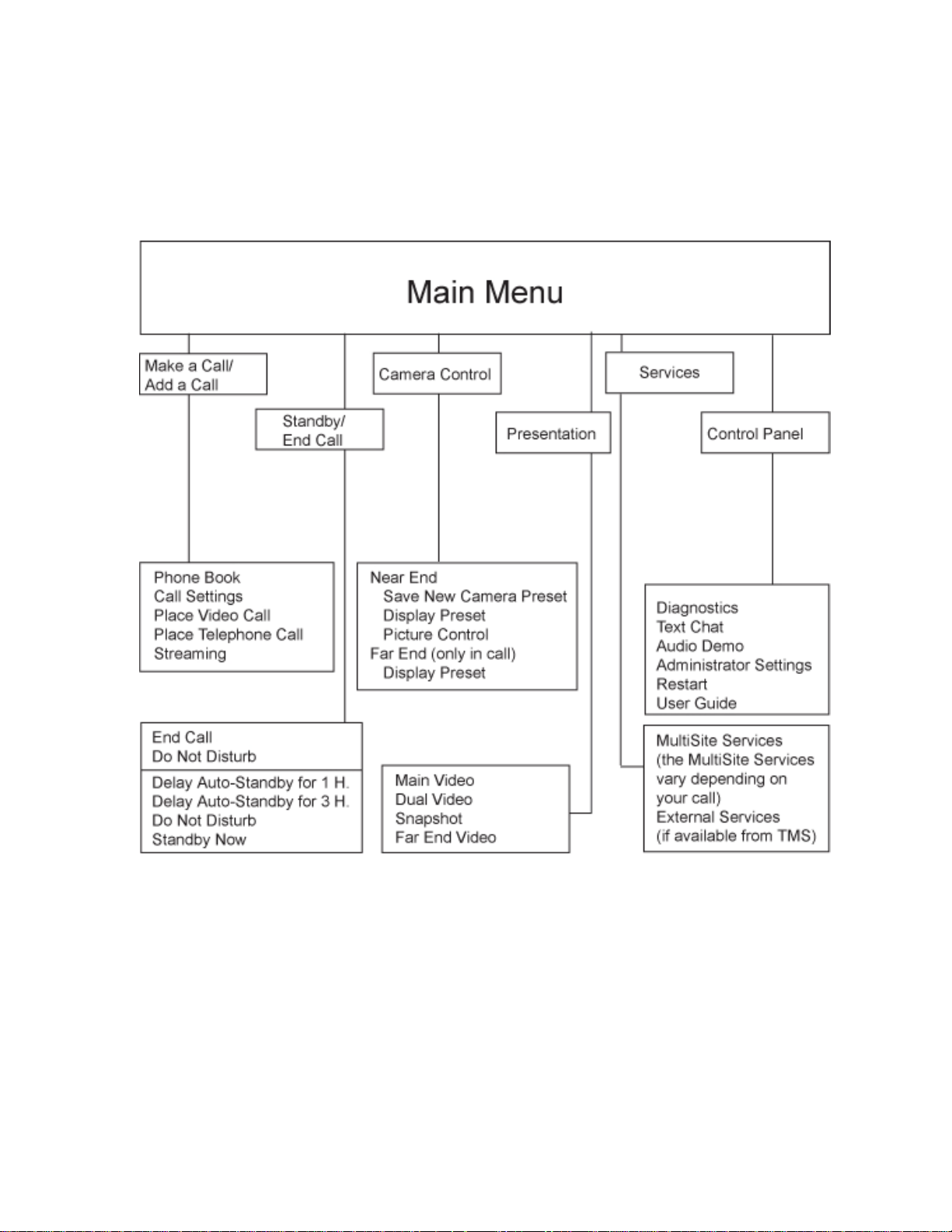
1.2 Menu Structure
1 Introduction
The menu structure is divided in three. The Kiosk Menu, which is available for all users when
Kiosk mode is activated, the Main Menu, which contains all functionality of the system and the
Administrator Menu that contains all the settings of the system.
The menu structure for Kiosk Menu is shown below.
Figure 1-2. Kiosk menu.
5
Page 14
TANDBERG COMPASS MXP / UTILITY MXP
The Main Menu and Administrator Settings are only accessible when Kiosk Menu is deactivated.
Select Control Panel and Administrator Settings from the Main Menu. Making changes to the
Administrator Settings will change the behavior of the system.
The menu structure for Main Menu and Administrator Settings is shown below.
Figure 1-3. Main menu.
6
Page 15
1 Introduction
Figure 1-4. Administrator Settings menu.
Note that the system features and menu settings may vary depending on network selection
and software package.
7
Page 16

TANDBERG COMPASS MXP / UTILITY MXP
2 Installation
Precautions:
Never install communication wiring during a lightning storm.
Never install jacks for communication cables in wet locations unless the jack is
specifically designed for wet locations.
Never touch uninstalled communication wires or terminals unless the telephone line has
been disconnected at the network interface.
Use caution when installing or modifying communication lines.
Avoid using communication equipment (other than a cordless type) during an electrical
storm. There may be a remote risk of electrical shock from lightning.
Do not use the communication equipment to report a gas leak in the vicinity of the leak.
Always connect the product to an earthed socket outlet.
The socket outlet shall be installed near to the equipment and shall be easily accessible.
1TR6 network type is not approved for connection directly to the telecommunications
network. This network type is only to be used behind a PABX.
This product complies with directives: LVD 73/23/EC, EMC 89/366/EEC, R&TTE 99/5/EEC
8
Page 17

2.1 Unpacking
2 Installation
The TANDBERG Compass MXP and Utility MXP consist of the following items:
Videoconferencing system with built-in camera, handset and lamp
Remote Control (Utility MXP only)
Batteries
User Manual on CD
Integrated power supply
Cables
High security keys
9
Page 18
TANDBERG COMPASS MXP / UTILITY MXP
2.2 Connecting Cables
Figure 2-1. Connectors.
3. LAN cable
To use the system on LAN,
connect a LAN cable from the
Ethernet' connector on the system
to the LAN.
1. Power cable
Connect the power cable
from the wallplate to the
power supply.
Note: The connection of
main electrical supply to
the wallplate is described
in the Installation Sheet.
2. ISDN cables
Connect the ISDN cables
to the ISDN connectors
on the system.
Connect the ISDN cables
to the ISDN sockets (S/Tinterface) provided by the
service provider. Your
main number will be the
number associated with
the socket to which ISDN
cable number 1 is
connected.
North America: The system does
not have a built-in network
terminator. If the wall socket
provides an ISDN U-interface, an
NT1 between the system and the
ISDN line is needed, see
Appendix 8 for details.
Note! Write down the
numbers associated with
each of the ISDN lines.
They are needed for
configuring the system
10
Page 19

2.3 Monitor Configuration
2 Installation
Power on
Switch the system on by connecting the power cable from the wallplate to the integrated power
supply. After the system has performed a self-test routine, the main menu will be displayed on the
monitor of the Utility MXP (units are shipped with Kiosk Mode OFF). The Compass MXP is
shipped with Kiosk Mode ON, and the monitor will therefore display the Kiosk Menu.
11
Page 20
TANDBERG COMPASS MXP / UTILITY MXP
2.4 System Configuration
The Compass MXP and Utility MXP have default settings from the factory enabling initial use.
However the system must be configured for each installation. Configuration settings can be made
via the system menu using the remote control, or more easily via telnet or web interface using IP.
The following screen pictures are based on remote control access directly on the system, whilst
the telnet or web interface gives a different visual layout but with the same configuration
possibilities. Refer to Appendix 7 Web Interface for more details.
Navigate through the menu system using the arrow keys and OK. Remember to press the Save
button on the bottom of each menu to save the changes. Press Cancel (x) to return to the
previous Menu. See General Use for more information about how to use the menus and the
remote control.
General configuration:
1. Open the General Settings menu
Press OK/Menu to open the Main Menu, if not already displayed. Select Control
Panel - Administrator Settings - General to open the General Settings menu.
Figure 2-2. General settings menu.
2. Language
Press OK in the Language field and select the wanted language from the list. Note:
This General / Language governs the language on the Setting and Screen Menus
when in normal mode. If multiple languages are desired in Kiosk mode then this is
defined within the Kiosk settings menu.
12
Page 21
3. System Name / International System Name
Enter a name in the System Name field using the number keys on the remote control,
in the same way as with a mobile or cellular phone. Hold down the # key for one
second to switch back and forth from numbers to alpha characters. The International
System Name field is only visible if the System Name contains supported Asian and
non-Latin text input.
4. Auto Answer, Phone Book Settings, External Services Settings and
Permissions
Utility MXP requires Auto Answer to be activated, it is also recommended for
Compass MXP. Otherwise these settings may be left unchanged if no special needs
are required. See chapter General Settings for more information.
5. Screen Settings
The settings may be left unchanged if no special needs are required. The display
layout may be changed at any time using the Layout button on the remote control.
6. Software Options
To activate options for the system, a new option key must be entered in the Software
Options menu (see paperwork accompanying the system). The Presenter option key
should be entered under “New Option Key”. Any bandwidth option key should be
entered under “New Bandwidth Key”. For more information on these options, please
contact your TANDBERG representative.
7. Date and Time Settings
Select your preferred Date and Time Settings.
8. Save changes
Remember to save any changes made in a menu by selecting the Save button on the
menu line and pressing OK.
Network configuration:
1. Open the Network menu
Press OK/Menu to open the Main Menu, if not already displayed. Select Control
Panel - Administrator Settings - Network to open the Network menu.
2 Installation
13
Figure 2-3. Network settings menu.
Page 22

TANDBERG COMPASS MXP / UTILITY MXP
2. ISDN configuration
Set the Network type to the desired network. Specify the settings for the selected
network in the relevant menu. For details, follow the instructions in ISDN-BRI
Settings.
3. LAN configuration
Select LAN Settings in the Network menu and specify the necessary LAN settings
according to the instructions from your LAN administrator. For details, follow the
instructions in LAN Settings. If there is an H.323 Gatekeeper present on your LAN,
refer to H.323 Settings as well.
4. Network Profiles
Please refer to Network Profiles for details
5. Data Port
Not available on this product.
6. Save changes
Remember to save any changes made in the menu by selecting the Save button on
the Menu line and pressing OK.
Kiosk Mode Settings:
Press OK/Menu to open the Main Menu, if not already displayed. Select Control Panel Administrator Settings – Menu Settings – Kiosk mode Settings to open the Kiosk Mode
Settings menu.
The default Kiosk Mode settings for the Utility MXP are:
- Language menu OFF
- Available languages check boxes with all languages*
- Auto dial ON
- Allow use of Remote Control YES
- Phone Book Local
- Kiosk menu OFF
After having configured the settings of the Utility MXP, you must activate Kiosk mode
by setting Kiosk Mode til ON. Be avare that you cannot deactivate kiosk mode again
through the menu, but only through the web interface, telent or the remote control.
The default Kiosk Mode settings for the Compass MXP are:
- Language menu OFF
- Available languages check boxes with all languages*
- Auto dial ON
- Allow use of Remote Control NO
- Phone Book Local
- Kiosk menu ON
After having configured the settings of the Compass MXP, you must activate Kiosk
mode by setting Kiosk Mode til ON. Be avare that you cannot deactivate kiosk mode
again through the menu, but only through the web interface, telent or the remote
control.
See Kiosk Mode Settings for more details.
14
Page 23

3 General Use
3 General Use
Wake up the system
When the system is not in use, it is in standby mode and the screen is black. Wake up the system
by picking up the handset. An incoming call or pressing any key on the Compass MXP will also
wake up the system.
Quick Key for IP Address
If the IP address of the system has been mislaid or forgotten it can be shown temporarily on the
screen by pressing the central button on the Compass MXP for at least 5 seconds, until the
address appears on the screen. On the Utility MXP the remote control can be removed from the
cabinet and the OK button pressed in the same manner.
Quick Key to Deactivate Kiosk Mode
If it is required to deactivate the Kiosk Mode without using the telnet or web interface the following
must be performed using the remote control stored inside the cabinet. This is only possible if the
setting Allow Use of Remote Control has been saved as ON. Please refer to later chapters on
where the remote control should be directed to enable IR reception.
Press 5 times on the Phone Book symbol then once on the number 3.
15
Page 24

TANDBERG COMPASS MXP / UTILITY MXP
3.1 The Welcome Screen (Normal
Mode)
When the system is switched on, the normal welcome screen will be displayed. The welcome
screen presents the menu and displays your main camera image in the background (main
camera is system default). The ISDN/IP numbers and the system name are displayed in the
upper right corner. The ISDN Number and IP Number are the dial-in numbers of the system.
The welcome screen provides you with the most important system information:
System Name
Your ISDN Number
Your IP Address or IP Number
It is possible to customize the text on the welcome screen. See Menu Settings for how to edit
welcome text.
Figure 3-1. The Welcome Screen in normal mode.
16
Page 25
3.2 The Welcome Screen (Kiosk
Mode)
3 General Use
When the system is switched on and Kiosk Mode is ON and Show Menu is ON the welcome
screen will be displayed. The welcome screen presents the menu and displays your main camera
image in the background.
An additional welcome screen can be shown if Language Menu is ON. The normal welcome
screen will appear after the language has been selected.
It is possible to customize the text on the welcome screen. See Menu Settings for how to edit
welcome text.
Figure 3-2. The Welcome Screen in Kiosk Mode.
17
Page 26

TANDBERG COMPASS MXP / UTILITY MXP
Figure 3-3. Language selection menu.
18
Page 27
3.3 Using the Remote Control
3 General Use
The Utility MXP is only controlled by the handset and from the far end. The system is not
designed to be controlled by a remote control accessible to the user. The remote control is only
for system setup and maintenance by authorized personnel. The IR receiver is a small hole just
below the speaker grill, the remote control must be held directly in front of the small hole.
The Compass MXP is controlled by the handset and the five buttons located on the cabinet. The
system is not designed to be controlled by a remote control accessible to the user. There is no
remote control delivered with the Compass MXP. System set-up must be done via telnet or web
interface.
Think of the remote control as a mobile phone with number keys and call keys. Use the arrow
keys and OK to navigate the menu. The system’s most commonly used functions are also
accessible directly from the remote control.
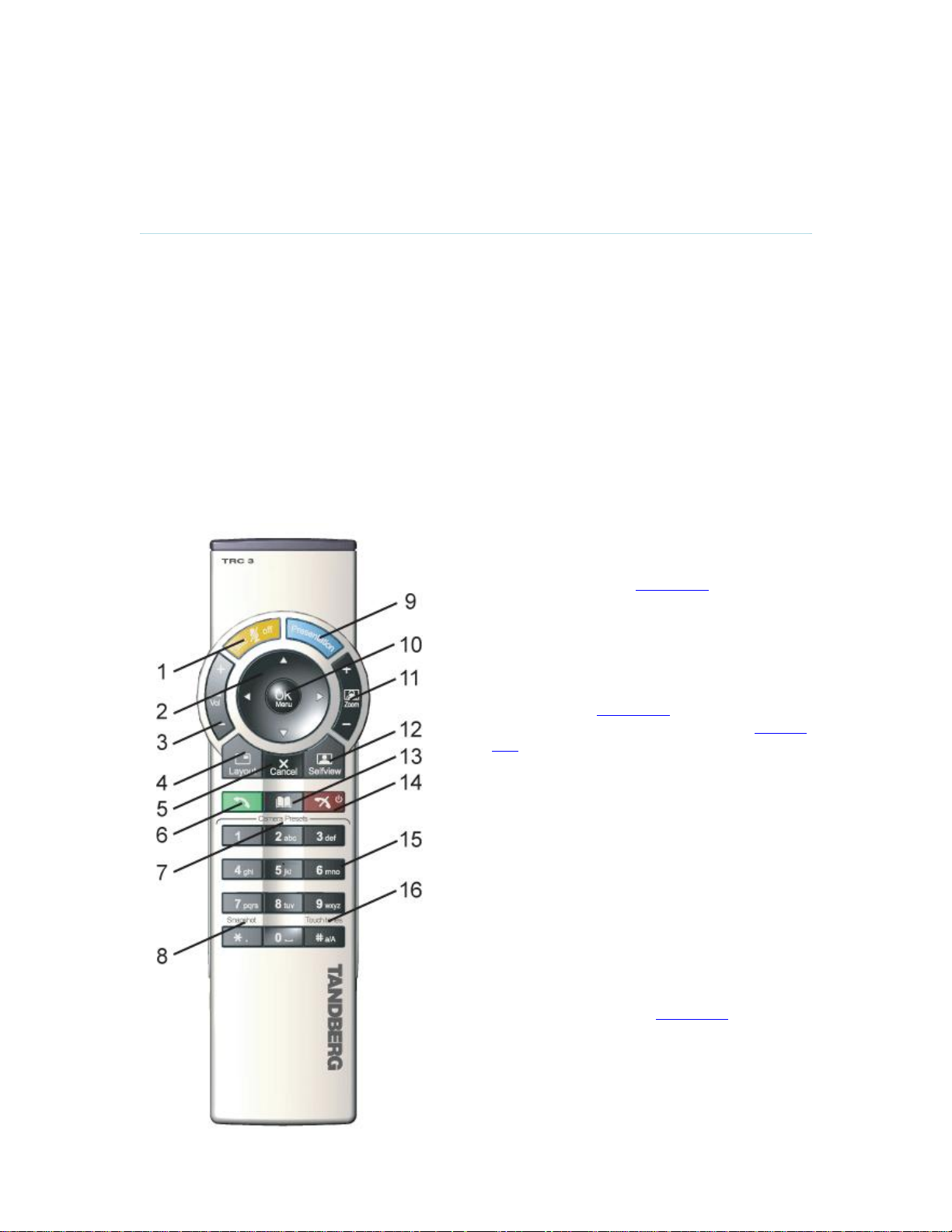
The TANDBERG remote control (TRC 3)
1. Mic Off turns your microphone on and off.
2. Arrow keys are used for navigation in the
menu and for moving the camera* when the
menu is hidden, see Navigation.
3. Volume + and – adjusts the Codec volume
only and not the monitor's volume.
4. The Layout key toggles between full screen
and different display layouts
5. Cancel takes you back one step in the menu
system. Use Cancel to delete characters in an
input field, see Navigation.
6. Press the Call key to place a call, see Place a
Call.
7. Camera presets* define specific camera
positions. Move the camera to the desired
position and press and hold a number key for
1 second to save the current camera position
to that number key. To activate a preset
whilst in a call, simply press and release that
number key.
8. Snapshot takes a snapshot of your video only
while you are in a call.
9. The Presentation key switches to a predefined
presentation source. If the Presentation key is
held down for 1 second then the Presentation
video sources menu will appear.
10. Press OK/Menu to show the menu and to
select menu items, see Navigation.
11. Use Zoom + and – to zoom the camera in and
out.*
19
Page 28

TANDBERG COMPASS MXP / UTILITY MXP
12. Selfview displays your outgoing video.
13. Use the Phone Book to store and recall
14. Use the red End Call key to end the
15. Number/Letter keys function in the same
16. Press Touch tones when you are in a
Figure 3-4. Remote Control.
*This does not apply to all systems with small integrated cameras.
Press Selfview again to turn selfview off.
video contacts for easy placement of
calls, see Phone Book.
current call. Pressing this key when not
in a call will place the system in Standby
mode, see End Call and Standby.
manner as with a mobile or cellular
phone, see Number and Letter keys.
call and need to dial extension numbers
etc. (instead of presets). Press the
OK/Menu button to exit Touch Tones.
20
Page 29
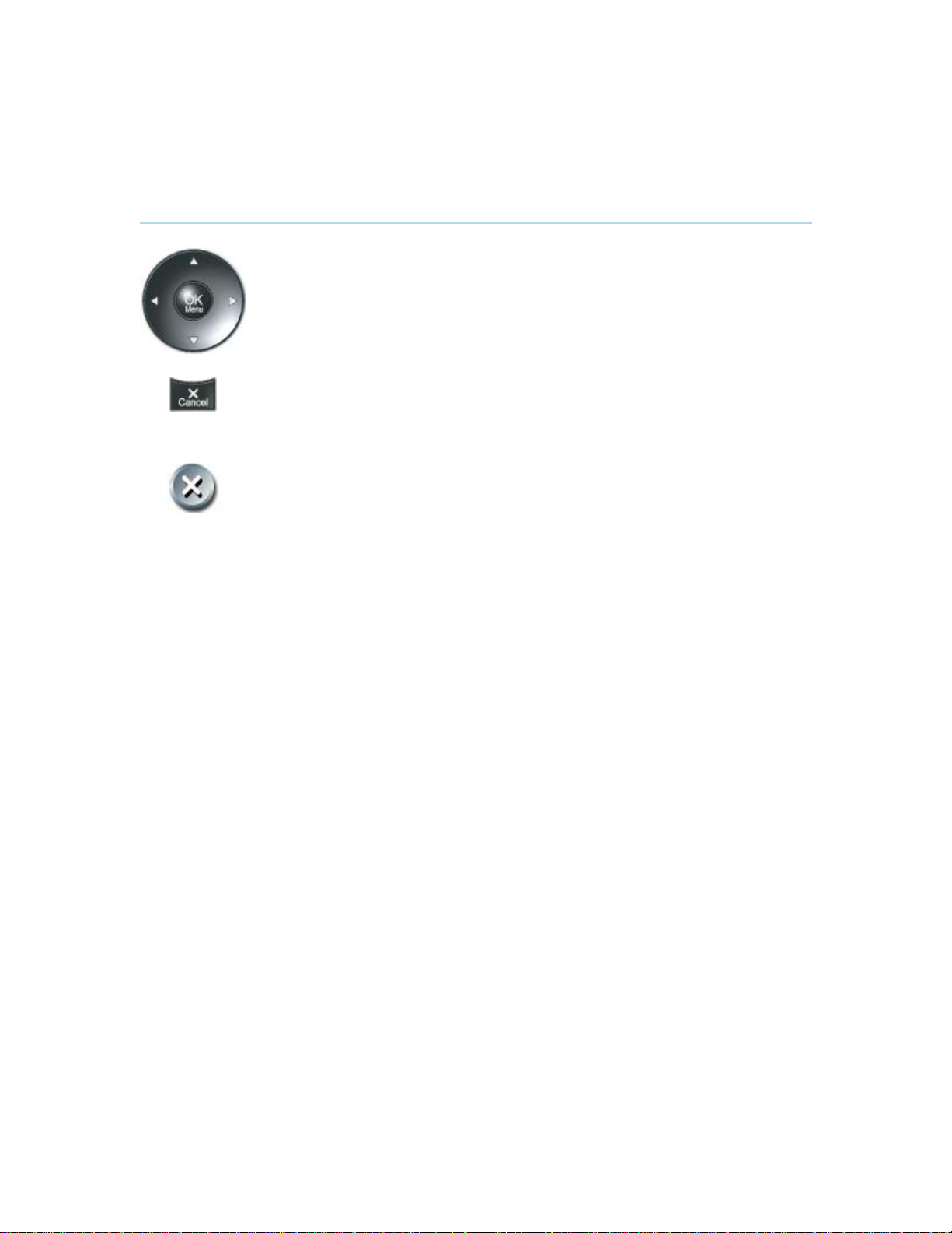
3.3.1 Navigation
3 General Use
Arrow keys and OK
Navigate in the menu with the arrow keys on the remote control. The
orange selector on screen shows the selected item. Press OK to select.
Cancel key
In the main menu, pressing Cancel (X) will hide the menu. If the menu is
hidden, bring it back with OK. In other menus, pressing Cancel (X) takes
you one step back. In an input field, pressing Cancel (X) will delete
characters/numbers to the left.
Back/Cancel button
The X button in the menu corresponds with the X key on the remote.
21
Page 30

TANDBERG COMPASS MXP / UTILITY MXP
3.3.2 Number and Letter keys
When accessing an input field where letters are required, the system automatically goes to letter
mode. Writing letters works like on a mobile phone. Press the key that corresponds to your
desired letter. Press the key as many times as needed to get the right letter. Change to lower or
back to upper case letters with the a/A key, and space with the 0 _ key.
To write numbers in a text input field, press the button through all the letters. Press once more
and the number will appear.
Example: How do I write "System 123" in the System Name input field (in General in
Administrator Settings)?
Press the 7-key four times to get an "S".
Press the #-key once to switch between upper case and lower case letters.
Press the 9-key three times to get a "y".
Press the 7-key four times to get an "s".
Press the 8-key once to get a "t".
Press the 3-key twice to get an "e".
Press the 6-key once to get an "m".
Press the 0-key once to get space.
Press the 1-key three times to get a "1".
Press the 2-key four times to get a "2".
Press the 3-key four times to get a "3".
22
Page 31

3.4 On-screen Indicators
3 General Use
The system has a number of icons signaling different settings:
Microphone Off
This indicator is shown when the microphone is turned off. Press the Mic off
button again to turn the microphone back on, see Mic Off for details.
Volume Off
This indicator is shown when the volume is turned off. Press Volume + to turn the
volume back on, see Volume + and - for details.
Secure Conference, AES
This double padlock indicator is shown when AES encryption (Secure
Conference) is active, see Security for details.
Secure Conference, DES
This padlock indicator is shown when DES encryption (Secure Conference) is
active, see Security for details.
Not Secure Conference
This open padlock indicator is shown during the initialization phase for AES or
DES encryption. During this period the call is not secure, see Security for details.
Warning
This indicates that the system has detected a warning. Select the icon and press
OK to see details on the warning. Please see Warnings for a list of possible
warnings.
Bad Network
This indicator appears if the system detects network anomalies like packet loss,
jitter etc., during a call. Open the menu by pressing the OK/Menu button and
select the warnings icon too see details.
23
Page 32

TANDBERG COMPASS MXP / UTILITY MXP
3.5 Using the Kiosk Menu
Figure 3-5. Kiosk Menu.
Press the left / right buttons on the Compass MXP to highlight the appropriate icon, then press
the central button to confirm selection.
The menu contains the following items:-
Place a Call
Volume
Close
24
Page 33

3.6 Using the Language Menu
3 General Use
Figure 3-6. Language selection menu.
The language selection menu is an optional menu, and is only active if Language Menu is ON in
the Kiosk Settings.
Press the left / right buttons on the Compass MXP to highlight the appropriate icon, then press
the center button to confirm selection.
25
Page 34

TANDBERG COMPASS MXP / UTILITY MXP
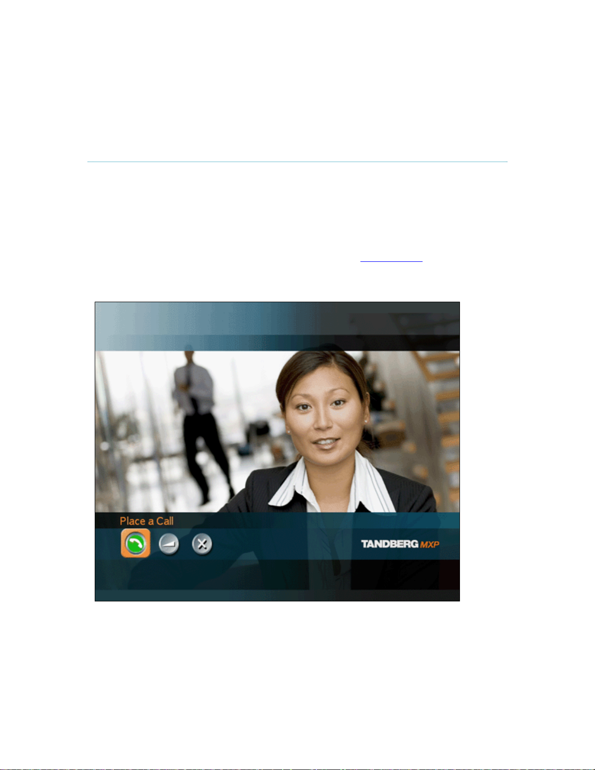
3.7 Place a Call
Autodial = ON
If Autodial is activated on either the Utility MXP or Compass MXP then a call can be placed by
simply lifting the handset from the cradle. The unit will then automatically call through the list of
names held in either the Local or Global phone book. If no connection is made after 7 seconds
the unit will proceed to the next name on the list. If the list is emptied without any connection the
system will repeat through the list.
Figure 3-7. Phone Book.
Autodial = OFF
If Autodial is not activated on the Compass MXP then it is possible to place a call using the five
buttons to navigate through the kiosk menu. To place a call on the Compass MXP first select
Place a Call on the main Kiosk Menu using the left / right buttons, then press the central button to
confirm the selection.
Then select the appropriate person or service to call by pressing the up / down buttons, and
center button to confirm the selection.
Selecting and confirming Back will return the user to the main Kiosk Menu.
26
Page 35

3.8 Receive a Call
3 General Use
How to answer an incoming call with Auto Answer = ON
If Auto Answer is activated then it is not necessary to lift the handset, the call will
automatically be answered and connected to the built in microphone and speaker, see
Auto Answer for details.
If wishing privacy within an Auto Answered call the user can pick up the handset, which
will automatically switch the system over to the handset microphone and speaker.
How to answer an incoming call with Auto Answer = OFF
To accept incoming calls on either the Compass MXP or the Utility MXP simply lift the
handset.
On the Compass MXP it is also possible to answer by pressing the middle of the five
buttons.
How to reject an incoming call:
To reject an incoming call on the Compass MXP select the Reject icon using the left /
right arrow buttons then press the central button to confirm.
It is not possible to reject a call on the Utility MXP.
Figure 3-8. Answering a call.
When idle, the system will accept all incoming calls as long as Incoming Telephone Calls are set
to On, see Permissions for details.
27
Page 36

TANDBERG COMPASS MXP / UTILITY MXP
3.9 End Call
Figure 3-9. Ending a call.
How to end an Auto Dial call
If Auto Dial is activated on either the Compass MXP or Utility MXP then replacing the
handset onto the cradle will end the call
How to end a non Auto Dial call (only possible on Compass MXP)
To end a call press the central button on the Compass MXP cabinet to display the on-
screen menu, then press the central button again to confirm the End Call selection
How to end an Auto Answer call
If the handset has been used on either the Compass MXP or Utility MXP together with
Auto Answer = ON then replacing the handset will not end the call.
Only the far end can end an Auto Answered call.
.
28
Page 37

3.10 Using the Handset
3 General Use
The handset has different functions depending on the setup of the unit, and depending on if the
unit is outside or inside a call.
When outside a call and with autodial activated, lifting the handset will waken the system
from standby mode and will start to dial through the names stored in My Contacts.
Replacing the handset onto the cradle will end the call.
When outside a call and with autodial deactivated, lifting the handset will waken the
system and show the Kiosk Menu if activated, otherwise self view will be shown.
Replacing the handset onto the cradle will have no consequence.
When an incoming call is ringing on the system and with auto-answer deactivated, lifting
the handset will accept the call. Replacing the handset onto the cradle will end the call.
When incoming call is ringing on the system and with auto-answer activated, lifting the
handset after the call has been auto-answered will switch between built-in speaker &
microphone and the handset. Replacing the handset onto the cradle after an autoanswered call will not end the call, but will switch back to the built-in speaker and
microphone.
When inside an existing call lifting the handset switches between the built-in loudspeaker
and microphone and those contained in the handset. This feature is the same for both the
Utility MXP and the Compass MXP. The switching is a toggling action, therefore upon
replacing the handset on the cradle the unit will switch back to the built-in speaker and
microphone.
The above description of handset functions can also be related to the actual units and their
default settings for Auto Answer and Auto Dial.
Utility MXP
(Default settings: Auto answer is ON and Auto dial is ON.)
Lifting the handset outside a call will wake up the system and start to dial the numbers listed in
the phone book. Thereafter, replacing the handset will end the call.
An incoming call will automatically connect the call with speaker active. Lifting the handset in a
call will switch from speaker mode to handset mode. If you hang up in a call, it will switch to
speaker mode again.
Compass MXP
(Default settings: Auto answer is OFF and Auto dial is ON)
Lifting the handset outside a call will wake up the system and start to dial the numbers listed in
the phone book. Thereafter, replacing the handset will end the call.
An incoming call will be connected by lifting the handset. Thereafter, replacing the handset on the
cradle will end the call. Note: If an incoming call is answered by pressing the central button,
29
Page 38

TANDBERG COMPASS MXP / UTILITY MXP
subsequent lifting of the handset will switch between speaker mode and handset mode, and
replacing the handset will not end the call
Alternative Compass (example)
(Settings: Auto answer is OFF and Auto dial is OFF)
Lifting the handset outside a call will wake up the system and you will see self view and the Kiosk
menu on the screen. Thereafter replacing the handset will make no change.
30
Page 39

3.11 Standby
3 General Use
The system will automatically go to Standby mode when it is not in use. In standby mode, the
screen and LED lamp are black. It is however still possible to receive incoming calls.
How to turn off the standby mode:
When the system is in standby, pick up the handset (on Compass MXP and Utility MXP)
or press any of the buttons on the Compass MXP to activate the system again.
The standby mode of the system should be used if the system is to be left idle.
31
Page 40

TANDBERG COMPASS MXP / UTILITY MXP
3.12 Phone Book - My Contacts
The Phone Book My Contacts is a list of contacts that can be stored locally on the system. Within
the normal operating mode (outside of Kiosk Mode) the list is known as My Contacts, and within
Kiosk Mode it is represented only as a list on the Make a Call screen.
The list of numbers within My Contacts is available for both Auto Dial (if activated) and for ringing
via the Make a Call menu (only possible on the Compass MXP).
It is possible to add new contacts and edit or delete existing contacts. My Contacts can store up
to 200 contacts.
It is possible to sort the names into a specific sequence by adding digits (e.g. 00-99) as a prefix to
the name. The list is sorted alphanumerically.
The settings box below depicts the My Contacts list when the Kiosk Mode is deactivated, i.e when
in set-up mode.
Note: With regard to Auto Dial and Make a Call, it is possible to select which Phone Book the
system uses; either the locally stored My Contacts or the list available via LAN and TMS known
as Corporate / Global Directory.
Figure 3-10. Phone Book – My Contacts.
32
Page 41

3.12.1 Add New Contact
3 General Use
The Add New Contact function is available from My Contacts.
It is recommended to add new contacts remotely using the IP address and the web-interface or
telnet.
To perform the following using the remote control the Kiosk Mode must first be deactivated. This
is done via the telnet or web-interface, or by pressing 5 times on the Phone Book symbol then
once on the number 3 on the remote control. The remote control can be directed to the inside
lower edge of the Compass MXP cabinet (i.e. the unit must be temporarily removed from the
wallplate). On the Utility MXP the remote control can be held directly in front of the small hole just
under the speaker grill.
Add a new contact to My Contacts by:
1. Select the New Contacts button to open the New Contacts dialog box.
2. Enter Name by using the letter keys on the remote control. Input will automatically be
interpreted as letters. Toggle between capital letters and small letters by pressing the #
button on the remote control. The maximum name length is 30 characters. For numbers,
press the # button for one second.
3. Enter Number by using the number keys on the remote control. Input will automatically be
interpreted as numbers. The maximum number length is 60 numbers. Use a star as
separator in IP addresses. For letters, press the # button for one second.
4. Alter the default setting of Call Type if necessary.
5. Alter the default setting of Network if necessary.
6. Alter the default setting of Bandwidth if necessary. For bandwidth 2x64 kbps or 2x56
kbps, two numbers are required, see Default Call Settings for more details.
7. Alter the default setting of Restrict (56k) if necessary.
8. Press OK to save.
Figure 3-11. Add New Contact
33
Page 42

TANDBERG COMPASS MXP / UTILITY MXP
3.12.2 Edit Contact
The Edit Contact function is available from My Contacts.
It is recommended to add new contacts remotely using the IP address and the web-interface or
telnet.
To perform the following using the remote control the Kiosk Mode must first be deactivated. This
is done via the telnet or web-interface, or by pressing 5 times on the Phone Book symbol then
once on the number 3 on the remote control. The remote control can be directed to the inside
lower edge of the Compass MXP cabinet (i.e. the unit must be temporarily removed from the
wallplate). On the Utility MXP the remote control can be held directly in front of the small hole just
under the speaker grill.
How to edit a contact in the Local Phone Book:
1. Select the contact that is to be edited.
2. Press the left arrow on the remote control, followed by the down arrow until the Edit
Contact icon is selected.
3. The current settings for this contact are displayed in a dialogue box. Alter the wanted
settings.
4. Press OK to save.
Figure 3-12. Edit Contact.
34
Page 43

3.12.3 Delete Contact
3 General Use
The Delete Contact function is available from My Contacts.
It is recommended to add new contacts remotely using the IP address and the web-interface or
telnet.
To perform the following using the remote control the Kiosk Mode must first be deactivated. This
is done via the telnet or web-interface, or by pressing 5 times on the Phone Book symbol then
once on the number 3 on the remote control. The remote control can be directed to the inside
lower edge of the Compass MXP cabinet (i.e. the unit must be temporarily removed from the
wallplate). On the Utility MXP the remote control can be held directly in front of the small hole just
under the speaker grill.
How to delete a contact:
1. Select the contact that is to be deleted.
2. Press the left arrow on the remote control, followed by the down arrow until the Delete
Contact icon is selected. The Delete Contact dialogue box is displayed.
3. Confirm by pressing the OK button again.
Figure 3-13. Delete Contact.
35
Page 44

TANDBERG COMPASS MXP / UTILITY MXP
3.12.4 Copy Contact to My Contacts
It is recommended to add new contacts remotely using the IP address and the web-interface or
telnet.
To perform the following using the remote control the Kiosk Mode must first be deactivated. This
is done via the telnet or web-interface, or by pressing 5 times on the Phone Book symbol then
once on the number 3 on the remote control. The remote control can be directed to the inside
lower edge of the Compass MXP cabinet (i.e. the unit must be temporarily removed from the
wallplate). On the Utility MXP the remote control can be held directly in front of the small hole just
under the speaker grill.
The Copy Contact to My Contacts function is available from the Last Number Dialed, Missed
Calls, Call History and Global Contacts folders, see Phone Book for details.
It may be wise to copy contacts that are often used to My Contacts. Note that the local copy will
not be updated if the Global Contacts are updated from the management system.
How to copy a contact from the Global Phone Book to the Local Phone Book:
1. Select the contact to be copied to My Contacts.
2. Press the left arrow on the remote control, followed by the down arrow until the Copy
Contact to My Contacts icon is selected.
A message box telling that the operation was successful will be displayed.
36
Page 45

3.13 Camera Control
3 General Use
The camera on the TANDBERG Compass MXP and Utility MXP is fixed and cannot be controlled
by the user. The focus is pre-adjusted from the factory to suit a normal face to face call. No user
adjustment is possible.
37
Page 46

TANDBERG COMPASS MXP / UTILITY MXP
3.14 Dual Stream
(DuoVideoTF/H.239)
Dual Stream is standard on the Utility MXP and Compass MXP. H.239 is the new ITU standard
defining how to send two video sources simultaneously.
With Dual Stream you have the opportunity to receive two different live video streams
simultaneously, main video and one additional source. This is handy when receiving a
presentation. You see the live presentation and the live video of the presenter simultaneously.
When the far end discontinues the Dual Stream the Utilty MXP or Compass MXP will switch over
to single stream.
It is not possible to send a Dual Stream from the Utility MXP or Compass MXP.
Dual Stream and Bandwidth
Using Dual Stream, the quality automatically downspeeds to the optimal bandwidth. This means
that you need higher quality to allocate enough bandwidth for the two video streams. Dual Stream
borrows bandwidth from main video. When Dual Stream is closed, the bandwidth is returned to
the main video.
38
Page 47

3.15 Control Panel
The control panel is only available when Kiosk Mode is deactivated.
3 General Use
Figure 3-14. Control Panel menu
The Control Panel contains the features:
Diagnostics
Text Chat
Audio Demonstration*
Administrator Settings
Restart
User Guide
* Audio Demonstration is not available on this product.
39
Page 48

TANDBERG COMPASS MXP / UTILITY MXP
3.16 Diagnostics
The diagnostics panel is only available when Kiosk Mode is deactivated.
Diagnostics allows testing of individual system components and displays the current system
settings.
Figure 3-15. Diagnostics menu.
Diagnostics contain:
System Information
Call Status
Channel Status
System Selftest
View Administrator Settings
IP Address Conflict Check
Warnings
40
Page 49

3.16.1 System Information
3 General Use
Select System Information to view system numbers, line status, software version, hardware serial
number and other useful information. Press arrow key up and down to scroll in the System
Information list.
System Information contains:
System Name
My ISDN Number
My IP Number
My IP Address
Table 1. System Information.
Note that the serial number is also found on a sticker on the system. It is
essential for identifying the system when it comes to service contracts or
other support activities. The serial number format is xx.xxxxx.
Software
Version
Internal Test
Software
Options
installed
Network
Lines active
Lines not active
Hardware
Serial
Number
MAC address
Ethernet
Speed
41
Page 50

TANDBERG COMPASS MXP / UTILITY MXP
3.16.2 Channel Status
Comprehensive information about the call progress is available through the Channel Status
window. This window indicates the various stages each B-channel goes through whilst
establishing a connection.
Status BRI
Idle
Calling
Connected
Sync
Active
Releasing
Released
Comments
the channel is idle
when calling — the network has acknowledged the call
when connection is established
when the channels are synchronized
when all available channels are connected
waiting for the network to confirm a release of the call
when disconnected - the network has acknowledged the disconnection
Table 2. Channel status.
Cause codes
The most common cause codes (for ISDN) are:
1
2
16
17
18
21
28
29
31
34
41
58
65
69
81
88
100
102
127
255
Unallocated (unassigned) number
No route to specified transit network (WAN)
Normal clearing
User busy
No user responding
Call rejected
Invalid number format (incomplete number)
Facility rejected
Normal, unspecified
No circuit/channel available
Temporary failure
Bearer capability not presently available
Bearer service not implemented
Requested facility not implemented
Invalid call reference value
Incompatible destination
Invalid information element contents
Recovery on timer expiry
Internetworking, unspecified
TANDBERG specific. undefined cause code
Table 3. Cause codes.
42
Page 51

3.16.3 Call Status
3 General Use
Comprehensive information about the call is available through the Call Status window. The menu
has two columns, one for transmitted and one for received audio/video/data information. If Dual
Stream is available on your system and in use, pressing the UP/DOWN keys will show one page
per connected site. Some of the information fields will vary dependent on if H.320 (ISDN calls) or
H.323 (IP calls) are made.
43
Page 52

TANDBERG COMPASS MXP / UTILITY MXP
3.16.4 System Selftest
The system performs a check to determine internal hardware integrity. System Selftest is useful
when you want to check if your network connection is active.
44
Page 53

3.16.5 View Administrator Settings
3 General Use
This window displays all the system settings. Use the arrow key on the remote control to scroll
through the list. The administrator settings available will vary within the MXP system range
depending on system and what software options installed.
View Administrator Settings may contain:
General Settings
Screen Settings
Software Options
Menu Settings
Presentation Settings
VNC Settings
System Name
Language
Dual Monitor
Auto answer
Max Call Length
Access Code
Incoming MCU calls
Incoming Telephone calls
Far End Control
Fallback to Telephony
TV Monitor Format
Picture Layout
VGA Monitor Format
VGA Out Quality
PC Picture Format
Allow VGA 50Hz
Options Installed
Serial Number
Current Option Key
Menu Timeout in Call
Welcome Menu
Welcome Picture
Logo
Balloon Help
Display Welcome Text
Welcome Text
Administrator Password
Duo Video Mode
Start up Video Source
Presentation Source
Snapshot Source
Auto Display Snapshot
PIP Appearance
PIP Placing
Address
Display Number
Call Quality
Video Algorithm
Audio Algorithm
45
Page 54

TANDBERG COMPASS MXP / UTILITY MXP
Interlaced
Video Quality
Default Call Settings
Audio Settings
Inputs
Level Settings
Outputs
Level Settings
Echo Control
Audio Levelling (AGC)
Alert Tones & Volume
Video Settings
Main Camera
PC
Document Camera
VCR
AUX
VNC
Split Screen
Call Type
Network
Bandwidth
Restrict (56k)
Auto H320 Bandwidth
Auto H323 Bandwidth
SIP
Mic1
Mic2
Mic3
Audio4
Audio5
Audio6
Mix Mode
VCR Ducking
Mic1
Mic2
Mic3
Audio4
Audio5
Audio6
Out1
Out2 (AUX)
Out3 (VCR)
Out1 Mode
Out1
Out2 (AUX)
Out3 (VCR)
Mic1
Mic2
Mic3
Audio4
Mics
Audio5 (AUX)
Audio6 (VCR)
Received Audio
Video Call Alert Tone
Telephone Alert Tone
Alert Volume
Alert Speaker
Key Tones
Camera Tracking Mode
MCU Status Line
Web Snapshot
46
Page 55

Picture Control
Video Name
Network Type
Advanced ISDN Settings
ISDN-PRI Settings
Channel Hunting
Advanced ISDN PRI Settings
Leased E1/T1 Settings
External network configuration
3 General Use
MultiSite Picture Mode
Focus
White balance
Brightness
Main Cam
AUX
Doc Cam
VCR
PC
VGA
VNC
ISDN-BRI\PRI\Leased E1\T1\Enternal
H331
ISDN Switch Type ETSI (Euro ISDN),…
Line1 Setup On
Number1
Number2
SPID1
SPID2
Line2 Setup On
Number1
Number2
SPID1
SPID2
Line3 Setup On
Number1
Number2
SPID1
SPID2
Subaddress
Validate Numbers (MSN)
Parallel Dial
Send Own Numbers
Sending Complete
Number Range
ISDN-PRI Switch Type
Max Channels
Low Channel
High Channel
Search High, Low
Line Settings:
T1 Cable Length 1
T2 Cable Length 2
E1 CRC-4
NSF Code Video
NSF Code Telephone Call
Call Control
Network Interface
Max Channels
Start Channels
T1 Line Coding
Line Settings
Call Control RS66
47
Page 56

TANDBERG COMPASS MXP / UTILITY MXP
RS449/V.35 Compatible
IP Settings
H.323 Settings
Advanced H.323 Settings
IP Precedence
Diffserv
SNMP Settings
Streaming Settings
Network Profiles
Security
Data Port 1
Data Port 2
IP assignment
IP address
IP subnet mask
Gateway
Ethernet Speed
E.164 Alias
Use Gatekeeper
Gatekeeper IP
H.323 Prefix
RSVP
NAT
NAT Address
QoS
Audio
Video
Data
Signaling
IP Type of Service (TOS)
Audio
Video
Data
Signaling
SNMP Trap Host1
SNMP Trap Host2
SNMP Trap Host3
SNMP Community
Address
Address Port
TTL/Router Hops
Streaming Source
Allow Remote Start
Announcements
Video rate (kbps)
Auto
H.320
H.323
Network Profile 4
Network Profile 5
Network Profile 6
Encryption
Encryption mode
Baud rate
Parity
Databits
Stopbits
Mode
Baud rate
Parity
Databits
Stopbits
Mode
48
Page 57

3.16.6 IP Address Conflict Check
3 General Use
The system will give a warning if there is an IP conflict. The user may initiate this check by
selecting IP Address Conflict Check.
49
Page 58

TANDBERG COMPASS MXP / UTILITY MXP
3.16.7 Warnings
If any warnings registered by the system it will be displayed in the Warnings menu. Open a
warning in the list to get more information about the warning.
Figure 3-16. Warnings.
The following warnings are displayed if detected by the system:
ISDN BRI warnings
ISDN is enabled on BRI line x, but the line is not connected. Please check your network
connection or disable the line. (101)
There is something wrong with ISDN BRI line x. Please check your network connection.
(102)
IP network quality warnings
The system is experiencing packet loss in the IP network. This may affect the quality of
the call.
The system is experiencing high jitter in the IP network. This may affect the quality of the
call.
The system is dropping IP packets due to latency in the network. This may affect the
quality of the call.
ISDN PRI warnings
ISDN PRI is configured for this system, but the line is not connected. Please check your
network connection or disable the network. (131)
There is something wrong with the ISDN PRI line (Blue alarm). Please check your
network connection. (132)
There is something wrong with the ISDN PRI line (Yellow alarm). Please check your
network connection. (133)
There is something wrong with the ISDN PRI line (D-Channel not active). Please check
your network connection. (134)
External Network warnings
External Network is configured for this system, but the line is not connected. Please
check your network connection or disable the network. (161)
Leased E1/T1 warnings
Leased E1/T1 is configured for this system, but the line is not connected. Please check
your network connection or disable the network. (191)
50
Page 59

3 General Use
There is something wrong with the Leased E1/T1 line (Blue alarm). Please check your
network connection. (192)
There is something wrong with the Leased E1/T1 line (Yellow alarm). Please check your
network connection. (193)
H323 gatekeeper warnings
Could not register to the gatekeeper.
The gatekeeper rejected to register the system. Another system is already registered with
the same alias or H.323 ID.
The max capacity on the gatekeeper is reached. Registration failed.
Tried to register to the gatekeeper without a valid alias. Registration failed.
The system is not allowed to register with this gatekeeper.
Can not find the gatekeeper. Check the gatekeeper configurations on the system.
51
Page 60

TANDBERG COMPASS MXP / UTILITY MXP
3.16.8 Text Chat
While in an ISDN or IP call to another system supporting Text Chat (T.140), select Text Chat from
the Control Panel. Enter text in the displayed window.
How to use Text Chat:
1. Choose Text Chat from the Control Panel to open the Text Chat window.
2. Enter text with the number keys like on a mobile phone. The text is sent to the far end
continuously letter by letter.
3. Press OK to end Text Chat and escape from the text chat window.
Note that Text Chat is supported in point to point calls only.
52
Page 61

3.16.9 Administrator Settings
3 General Use
Administrator Settings contains the configuration of the whole system. It is recommended to password protect Administrator Settings to prevent occasional users to make changes to the system. See Administrator Settings for further details.
53
Page 62

TANDBERG COMPASS MXP / UTILITY MXP
3.16.10 Restart
The restart is only available when Kiosk Mode is deactivated.
Restart the system by pressing the Restart button. You are prompted with a dialog box saying:
Do you want to restart the system? Press OK to restart, press Cancel (X) to abort.
Figure 3-17. Restart
54
Page 63

3.16.11 User Guide
3 General Use
The user guide is only available when Kiosk Mode is deactivated.
The on screen user guide takes you through a quick step-by-step introduction to
videoconferencing. It gives the user basic skills in how to use the system.
Figure 3-18. User Guide.
55
Page 64

TANDBERG COMPASS MXP / UTILITY MXP
4 Administrator Settings
The administrator settings are only available when Kiosk Mode is deactivated.
Figure 4-1. Administrator settings menu.
Administrator Settings contain all the settings of the system. Making changes to Administrator
Settings will change the behavior of the system. It is recommended to password protect the
access to Administrator Settings to prevent occasional users from making crucial changes to the
system, see Administrator Password.
Administrator Settings contain:
General
Menu Settings
Presentation Settings
Call Quality
Audio
Video
Security
Network
Restore Default Settings
56
Page 65

4.1 General Settings
4 Administrator Settings
The general settings are only available when Kiosk Mode is deactivated.
When installing the system, go through the General Settings menu to ensure that you have the
right settings for your system, see System Configuration.
Figure 4-2. General settings menu.
General Settings contain:
Language
System Name / International Name*
Autoanswer
Phone Book Settings
External Service Settings
Permissions
Screen Settings
Software Options
Date and Time Settings
* This field is only visible if the system name contains Asian and non-Latin character text input.
57
Page 66

TANDBERG COMPASS MXP / UTILITY MXP
4.1.1 Language
The system supports 16 different languages for its on-screen menus; English, German, French,
Norwegian, Swedish, Italian, Spanish, Portuguese, Russian, Finnish, Chinese Simplified, Chinese
Traditional, Japanese, Korean, Thai and Arabic. Select the preferred language and press OK to
save.
Note that pressing the Phone Book button 5 times followed by the number button 1 on the remote
control will reset the menu language to English.
58
Page 67

4.1.2 System Name
4 Administrator Settings
System Name identifies the system:
On the welcome page.
During an MCU conference call.
When using the Web-interface.
When the codec is acting as an SNMP Agent.
Towards a DHCP server.
H323 ID. Other systems can call in using this name instead of IP-number/IP-address.
System Name is blank by default. System name can be alphanumeric and up to 50 characters
long. Follow the installation procedure to enter a System Name.
Note that if the system name contains Asian and non-Latin character text input, the
International Name using Latin characters only, must be specified as well.
59
Page 68

TANDBERG COMPASS MXP / UTILITY MXP
4.1.3 International Name
If the System Name contains Asian and non-Latin character text input, the International Name
using Latin characters only, must be specified as well. This is in order to make other systems
understand the system name.
60
Page 69

4.1.4 Auto Answer
4 Administrator Settings
The auto answer setting decides whether an incoming call is put through automatically or
manually.
On
On+Mic
Off
Off
The system will automatically answer all incoming calls.
The system will automatically answer all incoming calls and switch the
microphone off when the call is connected. Press Mic Off to switch the
microphone on.
You must manually answer all incoming calls by pressing OK or the Call key.
61
Page 70

TANDBERG COMPASS MXP / UTILITY MXP
4.1.5 Phone Book Settings
Corporate Directory
On
Off
IP address
Enter the IP address of the management system that provides the Phone Book.
Path
The Path indicates the function of the management system.
The Corporate Directory is available in the menu.
The Corporate Directory is hidden from the menu and is unavailable for users.
62
Page 71

4.1.6 External Services Settings
4 Administrator Settings
External Services
On
Off
IP address
Enter the IP address of the service provider for External Services.
Path
Enter the Path to the External Services provider.
The services available are defined by the service provider.
When set to On External Services are available.
When set to Off External Services are unavailable.
63
Page 72

TANDBERG COMPASS MXP / UTILITY MXP
4.1.7 Permissions
Permissions contains settings for incoming telephone Calls, Far End Control, Remote Software
Upgrade and Fallback to Telephony.
Access Code
An access code will help you control the use of the system. All users must enter a code to identify
themselves and the call will be charged on their account. Access Codes are handy for group
systems where there are more users or divisions that share the costs of using the system. Access
Code can be set to "On" and "Off". Please refer to section Appendix 5 for more information on
Access codes.
On
Off
Incoming Telephone Calls
On
Off
Far End Camera Control
On
Off
When making a call, an Access Code dialog box will be shown. The user must enter
the correct password in order to put the call through.
No password is necessary to make a call.
The system will accept incoming telephone calls.
The system will not accept incoming telephone calls. This is useful to prevent
incoming calls from systems other than videoconferencing systems.
The far end will be able to:
• Control your camera
• Select your video sources
• Activate your camera presets
• Request snapshots
The far end can access none of the four features above on the local system. You will
however still be able to control the camera on the far end.
64
Page 73

4 Administrator Settings
Fallback to Telephony
When dialing a number and the system fails to place a video call to the number dialed, the
system will attempt to place a telephone call if Fallback to Telephony is enabled.
On
Off
Far End ISDN System Upgrade
It is possible to upgrade software remotely, i.e. a far end system may upgrade software on a local
system via http on ISDN. The system to be upgraded must be configured to allow remote
software upgrade. It is possible to set a password which is needed for the far end system to be
able to accomplish the software upgrade.
On
Off
Note that the configuration can also be done via the telnet or the serial port.
Maximum Call Length (minutes)
This feature will automatically end both incoming and outgoing calls when the call time exceeds
the specified Max Call Length. Max Call Length can have the following values: 0-999 (minutes),
where 0 means off.
Enables fallback from video calls to telephone calls.
Disables fallback.
The system will allow a remote system to upgrade local software.
The system will not allow a remote system to upgrade local software.
65
Page 74

TANDBERG COMPASS MXP / UTILITY MXP
4.1.8 Screen Settings
Auto Layout
On
Off
Note that when you receive low resolution images (176x144 pixels or less) the screen will
automatically adjust to a smaller view to give optimum quality experience.
Picture Layout
The Advanced Picture Layout is related to the Layout button on the remote control and it can be
used at any time to change the screen layout. For wide screen systems POP mode is
recommended. You will get optimized picture layouts for wide screen by pressing the Layout
button on the remote.
Picture in
Picture (PIP)
Picture
outside
Picture
(POP)
If Auto Layout is On the system will change layouts automatically depending on the
number of participants in a call and if you have a dual video stream or not. Please
refer to Layout for more information.
If Auto Layout is Off there will be no automatic layout changes during a call. All
desired layout changes must be done manually.
Pressing the Layout button on the remote will result in an extra picture in
smaller view (Picture in Picture). Press the Layout button to move it around
in the corners of the screen and finally hide it. Pressing and holding Layout
for 1 second will hide the small picture directly from any position.
Press the Layout button to see the images side-by-side, e.g. 1+1 layout,
where the far end and near end are displayed as images of equal size, see
figure below.
Press the Layout button once more to change to 1+2 layout. The far end
image will be displayed as the main video, with the near end, usually the
user of the system, as a smaller image in the upper right corner. If Duo
Stream is used, the Dual Stream image is displayed as the main image and
the far end and near end as smaller images to the right, see figure below for
an example.
Press the Layout button again to get the 1+3 layout.
The next time the Layout button is pressed, the normal full screen view of
the far end is displayed. Pressing and holding Layout for 1 second will
always bring you back to full screen.
66
Page 75

4 Administrator Settings
Figure 4-3. Example of Picture in Picture.
Figure 4-4. Example of 1+1 Side-by-Side view (wide screen).
Figure 4-5. Example of 1+2 Picture outside Picture (wide screen).
Figure 4-6. Example of 1+3 Picture outside Picture (wide screen).
67
Page 76

TANDBERG COMPASS MXP / UTILITY MXP
Note that the following menu settings do not apply for all TANDBERG MXP systems. Please
refer to the actual menu page on your system.
VGA Monitor Format
To fully leverage your wide screen display, activate the Native 16:9 format by setting the VGA
Monitor Format to Wide. Note that you should only change this setting if your VGA monitor is a
wide screen (16:9) monitor or projector. The VGA and DVI output will then be optimized for Wide
Screen VGA display.
Normal
Output format is optimized for Normal VGA monitors (4:3)
Wide
Output format is optimized for Wide VGA monitors (16:9)
Figure 4-7. Wide screen VGA or TV monitor in Normal (stretched) mode.
Figure 4-8. Wide screen VGA or TV monitor In Wide (native) mode.
VGA Out Quality*
The supported range of VGA formats will be optimized for the VGA display monitor based on the
source image.
VGA Out Quality enables the user to change the preferred format for the DVI/VGA output. It is
recommended to keep this setting in Auto unless your screen doesn’t support some of the XGA
or SVGA formats the system is using. Note that the VGA Out port support VESA Power
Management.
68
Page 77

4 Administrator Settings
Auto
SVGA 800x600
75Hz
XGA 1024x768
60Hz
VGA Out Quality for Wide XGA:
If VGA Monitor Format is set to Wide, PC Picture Format is set to Normal, VGA Out
Quality is set to Auto, the layout on the monitor is either fullscreen or POP, and the
input source to the largest window is PC with resolution 1024x768, the system will use
WideXGA (1280x768) instead of XGA, when the monitor supports this.
PC Picture Format (wide screen monitors only)
PC Picture Format setting only takes effect when TV or VGA Monitor Format is set to Wide. Use
this setting to determine if you want your PC presentations to be shown stretched in full screen,
or with correct aspect ratio using part of the widescreen display. With the VGA Out Quality set to
Auto the presentation will be of the best possible quality supported by the monitor.
Normal
Wide
VGA output will have 4:3 aspect ratio on wide screen monitor.
VGA output will utilize the wide screen monitor at full.
VGA output format will be optimized dependant of the video source format,
refresh and of the EDID information available.
Supported formats are:
SVGA (800x600) 75Hz
XGA (1024x768) 60Hz / 75Hz
WXGA (1280x768) 60Hz
VGA output format is forced to SVGA format (800x600) 75Hz
VGA output format is forced to XGA format (1024x768) 60Hz
Figure 4-9. PC presentation shown in Normal (correct ratio) mode.
69
Page 78

TANDBERG COMPASS MXP / UTILITY MXP
Figure 4-10. PC Presentation shown in Wide (stretched) mode.
70
Page 79

4.1.9 Software Options
4 Administrator Settings
In order to activate additional bandwidth, you need to enter a bandwidth key. A restart of the
system is required after entering a new option and/or bandwidth keys. If the key is invalid, the
original key will be used.
The following options are available:
1. No option
2. Bandwidth options
71
Page 80

TANDBERG COMPASS MXP / UTILITY MXP
4.1.10 Date and Time Settings
NTP IP
This is the NTP time server address from which the system can get updated time information.
See IP Services for more details.
Auto
Manual
IP Address
The IP Address for obtaining the date and time information.
Time Zone
Select the correct time zone for the location of your system.
Date Format
Choose between DD/MM/YY, MM/DD/YY, or YY/MM/DD as the desired date format.
Time Format
Select 12h or 24h time format.
Daylight Savings
On
Off
The NTP IP address is set automatically.
The NTP IP address is set manually.
Automatically adjust for daylight savings changes.
Do not adjust for daylight saving changes.
72
Page 81

4.1.11 Max Call Length
4 Administrator Settings
This feature will automatically end both incoming and outgoing calls when the call time exceeds
the specified Max Call Length. Max Call Length can have the following values: 0-999 (minutes),
where 0 means off.
73
Page 82

TANDBERG COMPASS MXP / UTILITY MXP
4.2 Menu Settings
The menu settings are only available when Kiosk Mode is deactivated.
Figure 4-11. Menu settings menu.
Menu Settings contain the settings:
Input Editor Language
Menu Timeout In Call
Balloon Help
Administrator Password
Kiosk Mode Settings
Startup
Icons
74
Page 83

4.2.1 Input Editor Language
4 Administrator Settings
When the Input Editor Language is set to Chinese, Korean or Japanese the user will be able to
enter Chinese / Korean / Japanese characters into an input field like the System Name or Phone
Book, using the remote control.
75
Page 84

TANDBERG COMPASS MXP / UTILITY MXP
4.2.2 Menu Timeout In Call
Main menu appears on the bottom line of the screen. Set Menu Timeout In Call to On if you want
the menu to time out automatically when you are in a call.
On
Off
The menu will time out automatically after 15 seconds if there is no activity on the
remote control. Menu timeout does only apply when you are in a call. Outside a call,
the menu will not time out.
The menu will not time out automatically. Press Cancel (X) to hide the main menu
manually.
76
Page 85

4.2.3 Balloon Help
4 Administrator Settings
It is possible to enable / disable the balloon help window.
On
Off
Choose On if you want help text windows to appear.
There will be no help text window.
77
Page 86

TANDBERG COMPASS MXP / UTILITY MXP
4.2.4 Administrator Password
It is recommended to put an Administrator Password on the system. The Administrator Password
can be maximum 5 digits long. The Administrator Password dialog box will pop up when you
choose Administrator Settings from the Control Panel. This will prevent occasional users from
going in to administrator settings. With an administrator password, you can ensure that your
system will behave in the same way every time and that only approved people are allowed to
make changes to the system.
78
Page 87

4.2.5 Kiosk Mode Settings
4 Administrator Settings
Kiosk Mode
In Kiosk Mode the system is set to a simplified state where it can be controlled with just the four
arrow keys and OK. You will get a simplified on-screen menu with only basic functionality
available:
make calls (using predefined contacts in the phone book)
receive calls
end calls
adjust volume
Note that deactivating the Kiosk Mode is only possible through the web interface, telnet or
data port, or by pressing 5 times on the Phone Book symbol then once on the number 3.
Using Kiosk Mode
Outside a call the Welcome Menu will be displayed:
Figure 4-12. Place a Call, Volume and Close.
79
Page 88

TANDBERG COMPASS MXP / UTILITY MXP
In a call, the system will display Far End video in full screen. If Max Call Length is set to a value
and the system is in a call, the system will display a warning when it is 5 minutes, 1 minute and
10 seconds left of the call. If pressing OK when the system is in a call, the following menu will be
displayed: End Call, Volume and Close.
The following Kiosk Mode settings allow you to make some adjustments to the system's behavior
in Kiosk Mode.
Kiosk Mode - Language Menu
Figure 4-13. Language selection menu.
If Language Menu is enabled you will first see the language selection menu. Select language and
the Welcome Menu will be displayed with your desired language.
On
Off
Kiosk Mode - Available Languages
In Kiosk Mode the system supports 7 different languages for its simplified on-screen menu;
English, German, French, Norwegian, Swedish, Italian and Spanish. Select the preferred
language.
When On the system will display the language menu as the first menu in kiosk mode.
When Off the system will display the welcome menu in English (default).
80
Page 89

Kiosk Mode - Auto Dial*
On
The system will automatically dial to the first contact in the Phone Book when he
handset is lifted. If this contact is busy, the system will call the second number in the
Phone Book and so on. If the user places the handset in the cradle, the system will
switch to Speaker Mode. Only the Far End system can end the call.
Off
The system will not make a call automatically when the handset is lifted.
* Applies only to systems with handset
Kiosk Mode - Allow Use of Remote Control
Yes
All keys on the remote control are enabled.
No
All keys except the arrow keys and OK key are disabled.
Kiosk Mode - Phone Book
Local
The system will use the Local Phone Book in Kiosk Mode.
Corporate
The system will use the Corporate Directory in Kiosk Mode.
Kiosk Mode - Kiosk Menu
On
The Kiosk Mode menus will appear on the screen.
Off
No menus or indicators will appear on the screen.
4 Administrator Settings
81
Page 90

TANDBERG COMPASS MXP / UTILITY MXP
4.2.6 Startup
Welcome Menu
The Welcome Menu contains the Main Menu, System Status, your System Name and dial in
numbers.
On
Off
Welcome Picture
The Welcome Picture is what you see in the background of the welcome menu.
Selfview
Off
Logo
It is possible to upload a company logo to the system. For more information about how to upload
a Logo, see Appendix 6. Set the Logo settings to On to display the logo.
On
Off
Note: The TANDBERG Logo will be displayed if no other company logo is loaded and logo is
enabled.
Display Welcome Text
The welcome text displays your system name and dial in numbers by default. It is possible to hide
this information by choosing Display Welcome Text Off.
The Welcome Menu is shown when the system wakes up from standby mode.
The Welcome Menu is not shown when the system wakes up from standby mode.
Press the OK button to open the welcome menu.
Selfview is shown in the background of the welcome menu. In most cases this
means that main camera is displayed and you can see the video image of
yourself.
No picture is shown in the background of the welcome menu.
Choose On if you want the company logo to appear in the background of the
welcome menu.
The logo is not displayed.
82
Page 91

4 Administrator Settings
On
Off
Welcome Text
You can change the welcome text to any text you like, instead of the default text. Remember that
Display Welcome Text must be On to be able to edit the welcome text.
Welcome text is displayed on the welcome menu.
Welcome text is not displayed on the welcome menu.
83
Page 92

TANDBERG COMPASS MXP / UTILITY MXP
4.2.7 Icons
The following indicator icons may be set to on or off:
Mic Off
Volume Off
On Air
Encryption
Bad Network
Telephone
See On-screen Indicators for details.
84
Page 93

4.3 Presentation Settings
4 Administrator Settings
The presentation settings are only available when Kiosk Mode is deactivated.
Figure 4-14. Presentation settings menu.
Presentation Settings contain:
Presentation Start
H.239
Startup Video Source
Presentation Source
Snapshot Source
Auto-Display Snapshot
PIP Appearance
PIP Placing
VNC Settings
85
Page 94

TANDBERG COMPASS MXP / UTILITY MXP
4.3.1 Presentation Start
If your system has Dual Stream capabilities, you can show two video streams at the same time
(see also Dual Stream). Presentation Start is Auto by default. This means that you will start Dual
Stream (a second video stream) automatically when starting a presentation. Dual Stream requires
the Presenter Option and H.263 video. To check which options are installed, see the System
Information menu in Control Panel.
Manual means that you manually choose if you want to start Duo Video or not every time you
start a presentation.
Auto
Manual
Dual Stream starts automatically when you start a presentation (in other words,
when you choose a second video source). If your system or the far end system is
not capable of Duo Video/H.239, you will not use Dual Stream, but rather send the
presentation source as your Main Video
When starting a presentation, select Presentation in the call menu and select Start
Presentation. Choose a video source from the list displayed on the screen.
86
Page 95

4.3.2 H.239
4 Administrator Settings
H.239 supports transmission of two video streams. It combines elements of Duo Video and
People+Content. If H.239 is disabled you will still be able to start TANDBERG Dual Video
Stream*
Enabled
Disabled
* The TANDBERG 550 MXP can only receive Dual Video Stream.
Enables H.239
Disables H.239
87
Page 96

TANDBERG COMPASS MXP / UTILITY MXP
4.3.3 Startup Video Source
The Startup Video Source is the video source on display when the system wakes up from
standby mode. If you use Main Camera as start up source, the system will start with Main
Camera every time the system wakes up from standby, regardless of what the previous user was
using.
You can change Startup Video Source to Main Camera, PC, Document Camera, VCR, AUX,
VNC or Current depending on what video sources you have available for your system. Choosing
Current will result in the last used video source before the system went to standby.
88
Page 97

4.3.4 Presentation Source
4 Administrator Settings
The Presentation Source is connected to the Presentation button on the remote. Pressing the
Presentation button will put the Presentation Source on display. Presentation Source is PC by
default*. You can change the Presentation Source to any video source and none. Choosing none
results in opening the Presentation menu when pressing the Presentation key.
* Only for systems with the PC video input available.
89
Page 98

TANDBERG COMPASS MXP / UTILITY MXP
4.3.5 Snapshot Source
When you take a Snapshot, you get a snapshot of the Snapshot Source. Current is the default
Snapshot Source. This means that you take a snapshot of the video source that is currently
active.
You can change the Snapshot Source to any video source. In this way you can program the
snapshot key to apply only for PC for instance. Press Snapshot and you will take a PC snapshot
regardless of what video source that is currently active.
90
Page 99

4.3.6 Auto-Display Snapshot
4 Administrator Settings
Select Auto to automatically display a received snapshot. Turn Auto-Display Snapshot Manual if
you wish not to have them displayed on the screen when they are sent or received. The
snapshots will be sent and received, but not displayed. With Auto-Display Snapshot set for
Manual, you must enter the Presentation menu to display a snapshot.
Auto
Manual
A sent or received snapshot will automatically be displayed on the screen.
A sent or received snapshot will not be displayed on the screen. To see the
snapshot, choose Display Snapshot in the Presentation menu.
91
Page 100

TANDBERG COMPASS MXP / UTILITY MXP
4.3.7 PIP Appearance
A Picture in Picture (PIP) is a smaller picture placed in one of the corners of the screen. The PIP
enables you to see an extra picture in your video conference.
Auto
On
Off
PIP Auto means that Picture In Picture will appear automatically when it is suitable.
A picture in picture is nice when you use Duo Video and you need an extra window
to see all the pictures. You can of course show or hide the PIP with the Layout
button on the remote anytime.
PIP On means that a Picture in Picture will always be displayed.
PIP Off means that PIP is not displayed automatically.
92
 Loading...