


 Loading...
TCM-453V/454VK
SERVICE MANUAL |
US Model |
|
Ver 1.1 1998. 3 |
Canadian Model |
|
AEP Model |
||
|
||
|
(TCM-453V/454VK) |
|
|
E Model |
|
|
East European Model |
|
|
Chinese Model |
|
|
(TCM-453V) |
Photo: TCM-454VK
Model Name Using Similar Mechanism |
NEW |
|
|
Tape Transport Mechanism Type |
MT-453V-118 |
|
|
SPECIFICATIONS
CASSETTE-CORDER
MICROFILM
TABLE OF CONTENTS
1. SERVICING NOTES ............................................... |
2 |
2.GENERAL
|
Preparing a Power Source ............................................... |
3 |
|
Recording ........................................................................ |
3 |
|
Playing a Tape ................................................................. |
3 |
|
Maintenance .................................................................... |
3 |
3. |
DISASSEMBLY ......................................................... |
4 |
4. |
MECHANICAL ADJUSTMENTS ....................... |
7 |
5. |
ELECTRICAL ADJUSTMENTS ......................... |
8 |
6.DIAGRAMS
6-1. |
Block Diagram ................................................................ |
9 |
6-2. |
Printed Wiring Board ...................................................... |
11 |
6-3. |
Schematic Diagram ......................................................... |
13 |
7. |
EXPLODED VIEWS ................................................ |
16 |
8. |
ELECTRICAL PARTS LIST ............................... |
19 |
SECTION 1
SERVICING NOTES
In this set, the S102 (power) detects REC/PLAYBACK on.
It is mounted on the MAIN board, and therefore the REC/PLAYBACK on cannot be detected with the MAIN board removed. When making an operation check and voltage check of mechanical deck with the MAIN board removed, fix the S102 at turn on.
[MAIN BOARD] (Conductor Side)
IC101
S102
Notes on chip component replacement
•Never reuse a disconnected chip component.
•Notice that the minus side of a tantalum capacitor may be damaged by heat.
SAFETY-RELATED COMPONENT WARNING!!
COMPONENTS IDENTIFIED BY MARK ! OR DOTTED LINE WITH MARK ! ON THE SCHEMATIC DIAGRAMS
AND IN THE PARTS LIST ARE CRITICAL TO SAFE OPERATION. REPLACE THESE COMPONENTS WITH SONY PARTS WHOSE PART NUMBERS APPEAR AS SHOWN IN THIS MANUAL OR IN SUPPLEMENTS PUBLISHED BY SONY.
ATTENTION AU COMPOSANT AYANT RAPPORT À LA SÉCURITÉ!
LES COMPOSANTS IDENTIFIÉS PAR UNE MARQUE !
SUR LES DIAGRAMMES SCHÉMATIQUES ET LA LISTE DES PIÈCES SONT CRITIQUES POUR LA SÉCURITÉ DE FONCTIONNEMENT. NE REMPLACER CES COMPOSANTS QUE PAR DES PIÈCES SONY DONT LES NUMÉROS SONT DONNÉS DANS CE MANUEL OU DANS LES SUPPLÉMENTS PUBLIÉS PAR SONY.
– 2 –

SECTION 2 GENERAL
This section is extracted from instruction manual.
SECTION 3
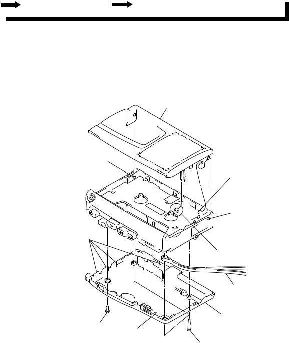
DISASSEMBLY
•This set can be disassembled in the order shown below.
SET |
CABINET (REAR), CASSETTE LID |
MAIN BOARD, MECHANISM DECK (MT-453V-118) |
|
|
 BELT
BELT
Note: Follow the disassembly procedure in the numerical order given.
CABINET (REAR), CASSETTE LID
9 cassette lid
7 boss
8 cassette spring
7 boss
3 four claws
6 Remove the two solders speaker cords.
5 strap
4 cabinet (rear)
2 screw
(IB lock) 3 claw
1 three screws
(B1.7 × 10)
– 4 –

MAIN BOARD, MECHANISM DECK (MT-453V-118)
5 three screws (IB lock)
1Remove the two solders electret condenser microphone (MIC901).
4 MAIN board
1Remove the two solders magnetic head (HRP901).
6 claw
7 mechanism deck (MT-453V-118)
1 Remove the two solders motor (M901).
3 screw
(M1.4)
2screw (1.7)
BELT
1 belt (capstan)
2 belt (FR)
– 5 –
Loading...