

Page 1
fелн~дд~нбзе=oЙимбкЙгЙенл
NOKOMNQ
pfkfrp=L=pfkfrp=`p=L=pfkfrp=qp
kÉï=~ë=çÑW==
bеЦдблЬ
=
Installation requirements
Page 2

Page 3

63 22 668 D3561
D3561.021.01.06.02 12.2014
3
Sirona Dental Systems GmbH Table of contents
Installation Requirements SINIUS / SINIUS CS / SINIUS TS
bеЦдблЬ
Table of contents
1
General information.................................................................................................. 5
1.1 Notes on the installation prerequisites .......................................................... 5
1.2 Structure of the document............................................................................. 6
1.2.1 Identification of danger levels........................................................... 6
1.2.2 Formats and symbols used .............................................................. 6
2
Safety information .................................................................................................... 7
2.1 Installation by qualified personnel ................................................................. 7
2.2 Radiotelephones ........................................................................................... 7
2.3 Modifications and extensions of the system.................................................. 7
2.4 Power connection.......................................................................................... 8
3
On-site installation.................................................................................................... 9
3.1 Substrate, floor.............................................................................................. 9
3.1.1 Load-bearing capacity of the floor.................................................... 9
3.1.2 Tensile forces................................................................................... 9
3.1.3 Stability............................................................................................. 10
3.2 Connection to the public drinking water system............................................ 11
3.3 Media quality ................................................................................................. 12
3.4 Underfloor installation of supply lines............................................................ 15
3.4.1 Installation template ......................................................................... 15
3.4.2 Installation of the supply line in the termination panel...................... 17
3.5 Cleaning the air and water pipes................................................................... 18
3.6 Underfloor installation of the PC connections ............................................... 19
4
Dimensions, technical data ...................................................................................... 20
4.1 SINIUS dimensions, scale bar 1:20 .............................................................. 20
4.1.1 Dimensions of the treatment room ................................................... 20
4.1.2 Side view.......................................................................................... 21
4.1.3 Top view........................................................................................... 22
4.1.4 Top view with options....................................................................... 23
4.1.5 Size of the treatment room with HELIODENT Plus.......................... 24
4.1.6 Side view with HELIODENT Plus..................................................... 25
Page 4

63 22 668 D3561
4 D3561.021.01.06.02 12.2014
Table of contents Sirona Dental Systems GmbH
Installation Requirements SINIUS / SINIUS CS / SINIUS TS
4.2 SINIUS CS dimensions, scale bar 1:20 ........................................................ 26
4.2.1 Dimensions of the treatment room ................................................... 26
4.2.2 Side view.......................................................................................... 27
4.2.3 Top view........................................................................................... 28
4.2.4 Top view with options....................................................................... 29
4.2.5 Size of the treatment room with HELIODENT Plus.......................... 30
4.2.6 Side view with HELIODENT Plus..................................................... 31
4.3 SINIUS TS dimensions, scale bar 1:20......................................................... 32
4.3.1 Dimensions of the treatment room ................................................... 32
4.3.2 Side view.......................................................................................... 33
4.3.3 Top view........................................................................................... 34
4.3.4 Top view with options....................................................................... 35
4.3.5 Size of the treatment room with HELIODENT Plus.......................... 36
4.3.6 Side view with HELIODENT Plus..................................................... 37
4.4 Mounting plates............................................................................................. 38
4.5 Information on planning for the practice........................................................ 40
4.6 Technical data............................................................................................... 41
4.7 Standards/Approvals..................................................................................... 44
5
Electromagnetic compatibility................................................................................... 46
5.1 Accessories................................................................................................... 46
5.2 Electromagnetic emission ............................................................................. 47
5.3 Interference immunity.................................................................................... 48
5.4 Working clearances....................................................................................... 50
5.5 Foot control wireless interface ...................................................................... 51
6
Checklist................................................................................................................... 52
6.1 Installation site .............................................................................................. 52
6.2 Construction requirements ............................................................................ 53
6.3 IT hardware ................................................................................................... 54
6.4 Network ......................................................................................................... 55
6.5 Data processing ............................................................................................ 56
Page 5

63 22 668 D3561
D3561.021.01.06.02 12.2014
5
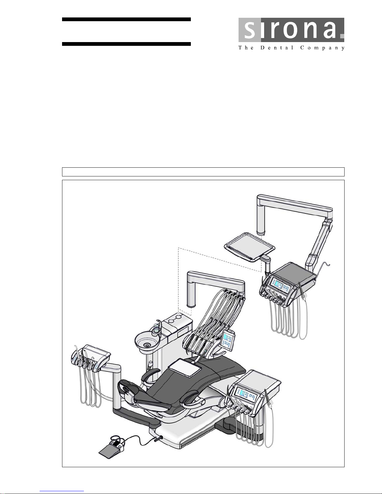
Sirona Dental Systems GmbH 1General information
Installation Requirements SINIUS / SINIUS CS / SINIUS TS 1.1Notes on the installation prerequisites
bеЦдблЬ
1
General information
1.1
Notes on the installation prerequisites
HYBRID product
This document describes the installation prerequisites for all versions of
the SINIUS / SINIUS CS / SINIUS TS treatment center.
It contains the following information:
● Required information for practice planning.
● Information for the installer and operator regarding the necessary
quality of the air and water supply media.
● Information for the installer, such as how to implement the
connections for air, water, waste water, suction air and the power
supply.
● Information on the cabling of the PCs to be connected.
● Information about electromagnetic compatibility and the prerequisites
for setting up the treatment center.
● A checklist to ensure that all installation requirements have been
fulfilled.
Reference to HYBRID installation instructions
The subsequent installation of the treatment center is described in the
installation instructions (REF 63 22 627).
You will also need the drilling template (REF 63 34 291) for the safe and
secure attachment of the treatment center to the floor.
Page 6

63 22 668 D3561
6 D3561.021.01.06.02 12.2014
1General information Sirona Dental Systems GmbH
1.2Structure of the document Installation Requirements SINIUS / SINIUS CS / SINIUS TS
1.2
Structure of the document
1.2.1 Identification of danger levels
To prevent personal injury and material damage, please observe the
warning and safety information provided in this document. Such
information is highlighted as follows:
Tip: Information on making work easier.
1.2.2 Formats and symbols used
The formats and symbols used in this document have the following
meaning:
DANGER
An imminent danger that could result in serious bodily injury or death.
WARNING
A possibly dangerous situation that could result in serious bodily injury
or death.
CAUTION
A possibly dangerous situation that could result in slight bodily injury.
NOTICE
A possibly harmful situation which could lead to damage of the product
or an object in its environment.
IMPORTANT
Application instructions and other important information.
Prerequisite
1. First action step
2. Second action step
or
➢ Alternative action
Result
➢ Individual action step
Prompts you to do something.
see "Formats and symbols
used [ → 6]"
Identifies a reference to another text
passage and specifies its page
number.
● List Designates a list.
"Command/menu item" Indicates commands, menu items or
quotations.
Page 7
63 22 668 D3561
D3561.021.01.06.02 12.2014
7
Sirona Dental Systems GmbH 2Safety information
Installation Requirements SINIUS / SINIUS CS / SINIUS TS 2.1Installation by qualified personnel
bеЦдблЬ
2
Safety information
2.1
Installation by qualified personnel
Installation by qualified p ersonnel
The installation of the supply connections must be carried out by qualified
technicians only.
Electrical and water supply installations; reference for INST suction machines
2.2
Radiotelephones
Mobile RF communications equipment can affect electro-medical
equipment. Therefore, the use of mobile wireless phones in medical office
or hospital environments must be prohibited.
2.3
Modifications and extensions of the system
Modifications to this system which might affect the safety of the system
owner, patients, or other persons are prohibited by law.
For reasons of product safety, this product may be operated only with
original Sirona accessories or third-party accessories expressly approved
by Sirona. The user assumes the risk of using non-approved accessories.
If any devices not approved by Sirona are connected, they must comply
with the applicable standards, e.g.:
● IEC 60950-1 for information technology equipment (e.g. PC) and
● IEC 60601-1 for medical electrical equipment.
The treatment center monitor must fulfill the requirements of the
IEC 60950-1 standard.
The loudspeaker port of the monitor may be connected only to a device
that complies with IEC 60950-1 (e.g. a PC) or
IEC 60601-1. Under no circumstances may it be connected to a stereo
system or the like.
If a system is created during the installation process, the requirements of
IEC 60601-1, 3rd edition, must be fulfilled. The person assembling the
system assumes responsibility for ensuring conformity, e.g. acc. to
Directive 93/42/EEC.
WARNING
Professional installation
Comply with the national regulations for electrical installation
(e.g. IEC 60364-1, VDE 0100-100, IEC 60364-7-710, VDE 0100-710,
National Electrical Code).
Comply with the national regulations for water supply installations
(e.g. EN 1717) and sewage installations (e.g. EN 12056-1).
For suction lines: adhere to the specifications in the installation
instructions for "Suction machines".
Page 8
63 22 668 D3561
8 D3561.021.01.06.02 12.2014
2Safety information Sirona Dental Systems GmbH
2.4Power connection Installation Requirements SINIUS / SINIUS CS / SINIUS TS
2.4
Power connection
WARNING
Shock hazard
It is essential that you switch off the power supply PRIOR to beginning
the installation. There is a risk of electric shock. People can be injured
or electrical components of the unit destroyed.
Page 9
63 22 668 D3561
D3561.021.01.06.02 12.2014
9
Sirona Dental Systems GmbH 3On-site installation
Installation Requirements SINIUS / SINIUS CS / SINIUS TS 3.1Substrate, floor
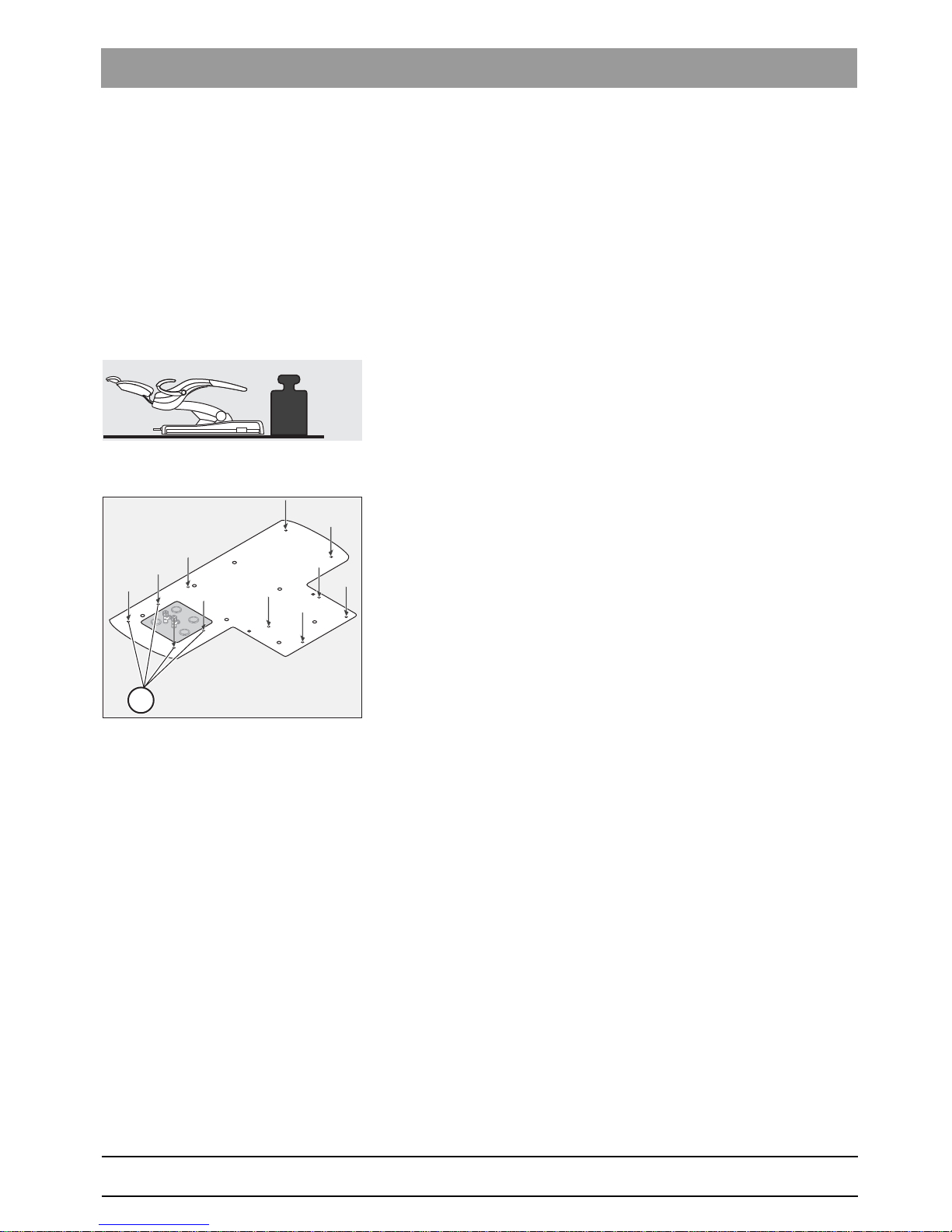
bеЦдблЬ
3
On-site installation
3.1
Substrate, floor
Level floor, steel adapter plate
Unevenness The floor must be level and horizontal in accordance with DIN 18 202.
In the case of an uneven floor, the steel adapter plate must be used; see
Mounting plates [ → 38].
3.1.1 Load-bearing capacity of the floor
Load capacity:
The minimum load-bearing capacity of the floor must be 0.5 N/cm
2
(corresponds to around 500 kg/m
2
).
3.1.2 Tensile forces
The floor must be able to accommodate tensile forces of > 1 kN at each
of the marked screw fastening points (A).
It may be necessary to reinforce the surface beneath the floor.
When using a mounting plate (see Mounting plates [ → 38]) this
requirement is mandatory.
0,5
N/cm
2
0,7
lbs/sq in.
A
Page 10

63 22 668 D3561
10 D3561.021.01.06.02 12.2014
3On-site installation Sirona Dental Systems GmbH
3.1Substrate, floor Installation Requirements SINIUS / SINIUS CS / SINIUS TS
3.1.3 Stability
With a concrete floor/SINIUS
With a concrete floor
● Use a 12 mm dia. masonry drill to drill the holes.
● The depth of the drill hole (C) in the concrete floor must be at least 80
mm.
● The specified drilling depth (C) of at least 80 mm refers to the drilling
length without screed (A) or impact sound insulation (B). The heavy
duty anchor bolts included with delivery (2 units) are suitable for a
clamping length ((A)+(B)) of up to 100 mm.
● Use 12 mm dia. wall plugs (but do not use wall plugs instead of heavy
duty anchor bolts).
● Use 10x160 mm wood screws including washers.
With a wooden floor
With a wooden floor
● Provide and prepare appropriate supporting beams.
● Use a 7mm dia. wood drill to drill the holes.
● The depth of the drill hole must be at least 80mm.
● Use 10x80mm wood screws including washers.
ATTENTION! Do not use wall plugs!
Ø 12mmØ 12mm
20mm
7mm
160mm160
mm
80
mm
min.
80
mm
min.
C
B
A
100
mm
max.
100
mm
max.
WARNING
Any existent screed (A) and/or impact sound insulation (B) must be
penetrated!
Ø 7mmØ 7mm
7mm
80
mm
min.
80
mm
min.
Page 11
63 22 668 D3561
D3561.021.01.06.02 12.2014
11
Sirona Dental Systems GmbH 3On-site installation
Installation Requirements SINIUS / SINIUS CS / SINIUS TS 3.2Connection to the public drinking water system
bеЦдблЬ
3.2
Connection to the public drinking water system
Disinfection system, opti onal
Treatment center isolated from the public drinking water supply
The treatment center, provided it is equipped with a disinfection system,
complies with the requirements of EN 1717 (free discharge with an
isolation distance ≥ 20 mm) and the DVGW German Gas and Water
Association). It is intrinsically safe according to the W540 worksheet and
thus also complies with W270 and KTW (Guideline on the use of plastics
in contact with drinking water). It can be connected directly to the public
drinking water system.
The treatment center then has the "DVGW" label next to the rating plate.
Treatment center not isolated from the public drinking water supply
If compliance with EN 1717 is required in the country, the respective
measures for the protection of public drinking water must be taken
outside the treatment center.
This applies to models without a disinfection system.
The treatment center then does not have the "DVGW" label.
Please comply with the national requirements with regard to connecting
treatment centers to the public drinking water system.
Page 12
63 22 668 D3561
12 D3561.021.01.06.02 12.2014
3On-site installation Sirona Dental Systems GmbH
3.3Media quality Installation Requirements SINIUS / SINIUS CS / SINIUS TS
3.3
Media quality
Description of media quality
Water quality
1 bar = 14.5 psi
p 0,18 bar
u
<
> 500 l/min
Wasserhärte
Dureté de l’ eau
Water hardness
Dureza del agua
1,4 mmol l 8° dH/ (= )
> 80 m 0,08 mmµ( )
> 3 l/min
2,5 bar p 6,0 bar<<5,5 bar p< < 7,5 bar
> 50 l/min
K
Suction machine
Compressed air (oil-free)
The compressor must draw in hygienically faultless air.
Cold water (drinking water quality)
K Steam trap
Page 13

63 22 668 D3561
D3561.021.01.06.02 12.2014
13
Sirona Dental Systems GmbH 3On-site installation
Installation Requirements SINIUS / SINIUS CS / SINIUS TS 3.3Media quality
bеЦдблЬ
Water quality
GA231
Lime deposits and corrosion residues in tap water can lead to the
following malfunctions:
● Premature clogging of the filters in the unit
● Rapid clogging of the fine water paths and jets in the treatment
instruments
For these reasons, the following points must be observed:
● Permitted water pressure: 2.5bar (36.25psi) to 6bar (87psi)
● Permitted minimum flow volume: 3l/min
● For water hardness (total hardness) of 2.2 mmol/l (= 12° dH ), install
water softeners.
Set the blend hardness to 1.4 mmol/l (= 8° dH).
● Install a conventional fine filter; fineness: > 80 µm (0.08 mm).
● Installation must be performed in compliance with the
recommendations of the national installation requirements (e.g. EN
1717/DIN 1988).
● The water quality must comply with the national requirements for
drinking water.
● The connection must be made to cold water.
● When laying the water pipe to the treatment center, comply with the
following instructions to reduce the quantity of micro-organisms in the
feed pipe:
– Avoid long stub lines to the treatment center.
– Carry out the installation so that, where possible, other main
consumers (such as the sink) are fed from the same line
downstream of the treatment center connection.
– Avoid laying the supply line parallel to hot water pipes.
● Before installation, an acceptable microbiological water quality
(drinking water) must be ensured and documented in the form of a
colony count.
● Sampling and the colony count must be performed by a competent
laboratory.
● The colony count must fulfill the national regulations for drinking
water and must not exceed 500 CFU/ml under any circumstances
(CFU: colony forming units).
● In the event of an increased colony count, the indoor installation must
be checked and the cause of contamination eliminated. Alternatively,
a stand-alone water supply can also be installed.
Page 14

63 22 668 D3561
14 D3561.021.01.06.02 12.2014
3On-site installation Sirona Dental Systems GmbH
3.3Media quality Installation Requirements SINIUS / SINIUS CS / SINIUS TS
● Observe EN 1717 for the protection of public drinking water.
Treatment center with disinfection system:
The treatment center fulfills the requirements of EN 1717 and that of
the DVGW (the German Technical and Scientific Association for Gas
and Water). It is intrinsically safe in accordance with worksheet
W540. It can be connected directly to the public drinking water
supply.
Treatment center without disinfection system:
If compliance with EN 1717 is stipulated, appropriate equipment must
be installed beyond the treatment center to protect the public drinking
water system.
Air quality
Air quality
The compressed air for driving the highspeed handpiece, for cooling the
burr drives and for the cooling spray must be free from oil, dry and
hygienically faultless.
Install a steam trap K.
● Permitted air pressure: 5.5bar (80psi) to 7.5bar (109psi)
● Permitted minimum flow volume: 50l/min
Suction pipe
With a vacuum of pu > 0.18 bar without flow, the treatment center must
be retrofitted with the "Vacuum limiter" retrofit kit (REF 59 68 826).
● Minimum suction power: 500l/min
● Maximum vacuum: 0.18bar (2.6psi)
Page 15
63 22 668 D3561
D3561.021.01.06.02 12.2014
15
Sirona Dental Systems GmbH 3On-site installation
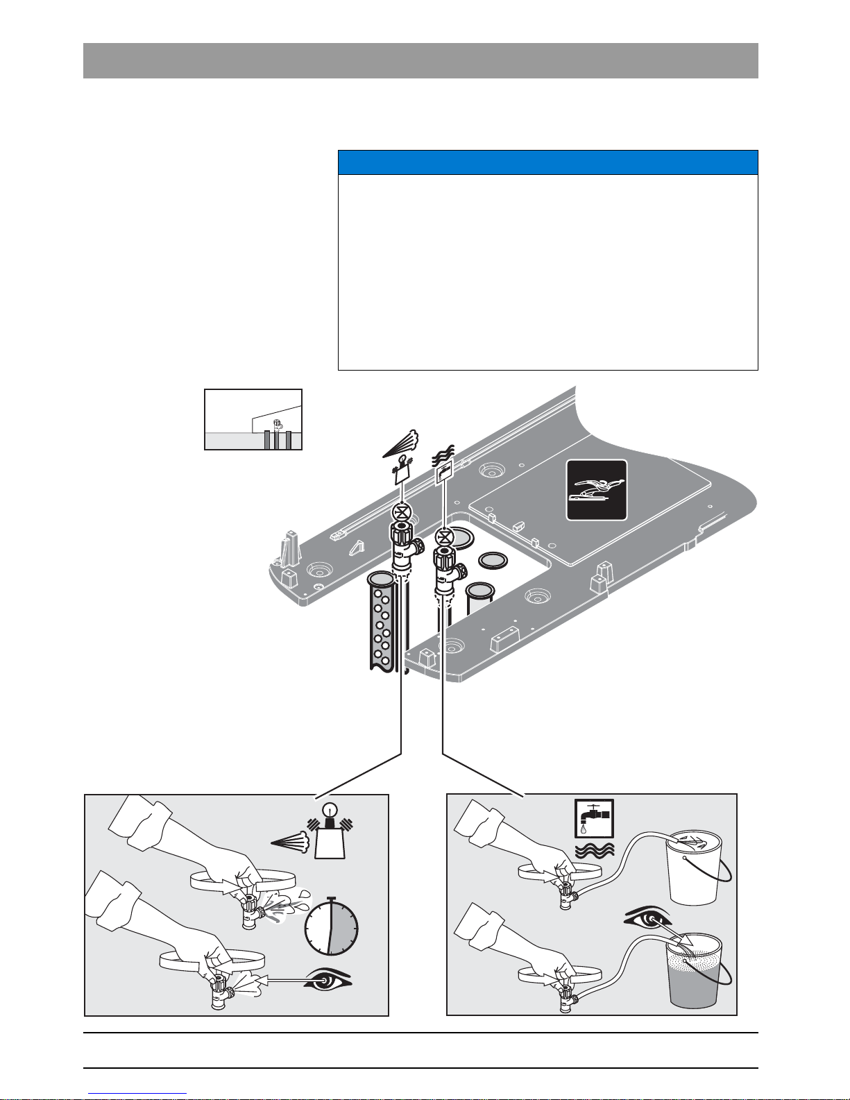
Installation Requirements SINIUS / SINIUS CS / SINIUS TS 3.4Underfloor installation of supply lines
bеЦдблЬ
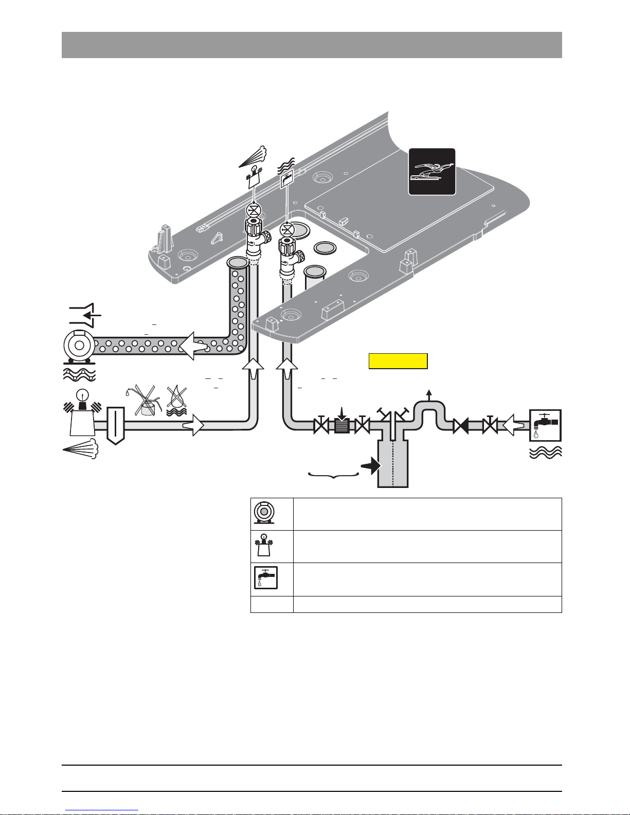
3.4
Underfloor installation of supply lines
3.4.1 Installation template
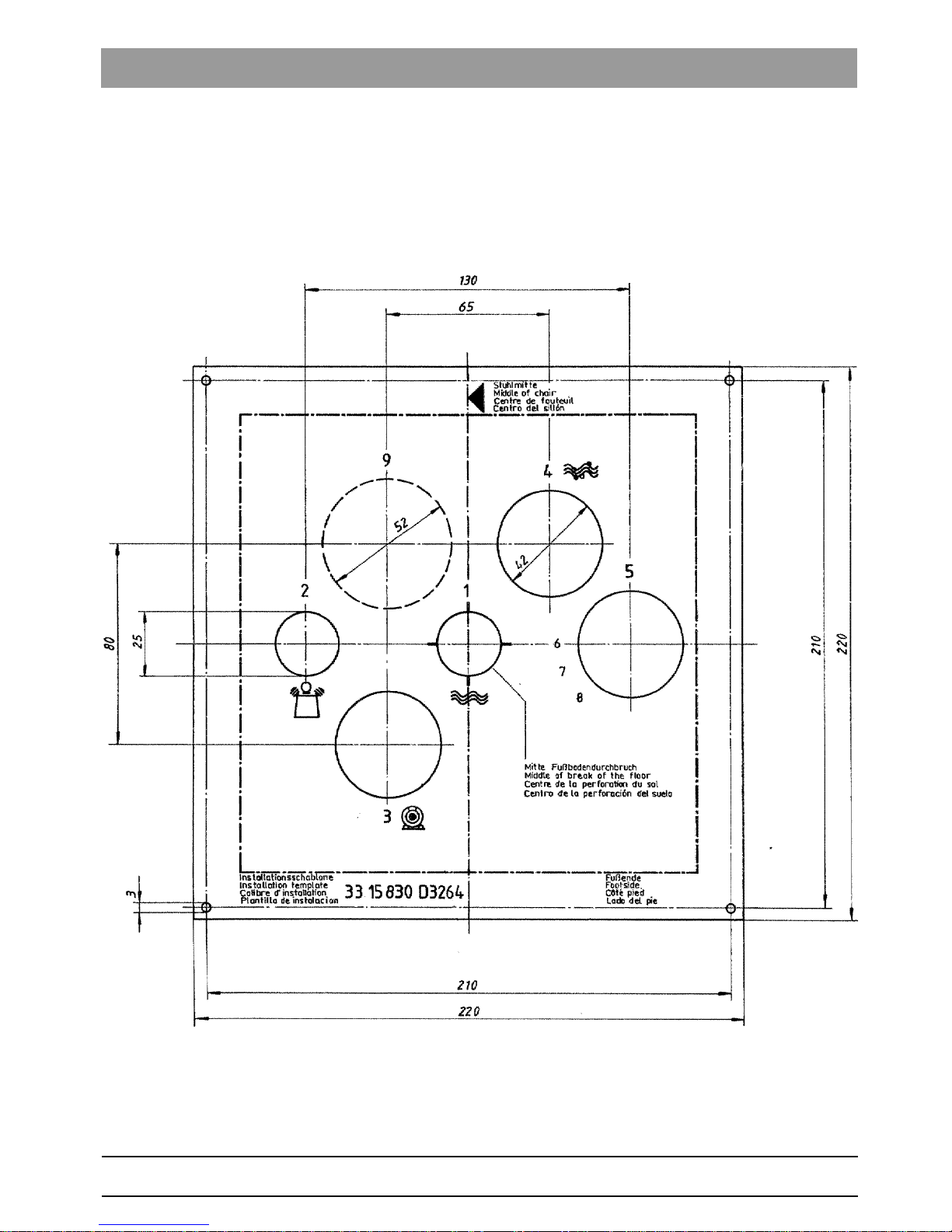
We recommend that you order the installation template (REF 33 15 830)
from Sirona for laying the pipe ends in the installation field. If necessary,
you can also prepare the template yourself based on the diagram below.
Table for template
Page 16

63 22 668 D3561
16 D3561.021.01.06.02 12.2014
3On-site installation Sirona Dental Systems GmbH
3.4Underfloor installation of supply lines Installation Requirements SINIUS / SINIUS CS / SINIUS TS
1 Water supply
Pipe 10x1 mm, corner valve outlet 3/8"
2 Compressed air supply
Pipe 10x1 mm, corner valve outlet 3/8"
3 Suction line
DN40 HT-PP ISO 8283-3
(polypropylene, inner diameter 36.5 mm)
4 Water drainage
DN40 HT-PP ISO 8283-3
(polypropylene, inner diameter 36.5 mm)
5 Installation pipe
DN40 HT-PP ISO 8283-3
(polypropylene, inner diameter 40 mm)
6 Control cable to relays for the
suction machine ( ),
call cable ( ),
Special function (#)
3 x 1.5 mm
2
(quality as in the power cable)
7 Power supply
3x1.5 mm
2
Circuit breaker: for 230 VAC: 16 A slow-blow
for 100 - 115 VAC: 20 A slow-blow
Recommended: Type B automatic circuit breaker
8 not connected
9 Installation pipe, inner diameter 50 mm
(or corresponding flat conduit) for the PC connection
%
Page 17
63 22 668 D3561
D3561.021.01.06.02 12.2014
17
Sirona Dental Systems GmbH 3On-site installation
Installation Requirements SINIUS / SINIUS CS / SINIUS TS 3.4Underfloor installation of supply lines
bеЦдблЬ
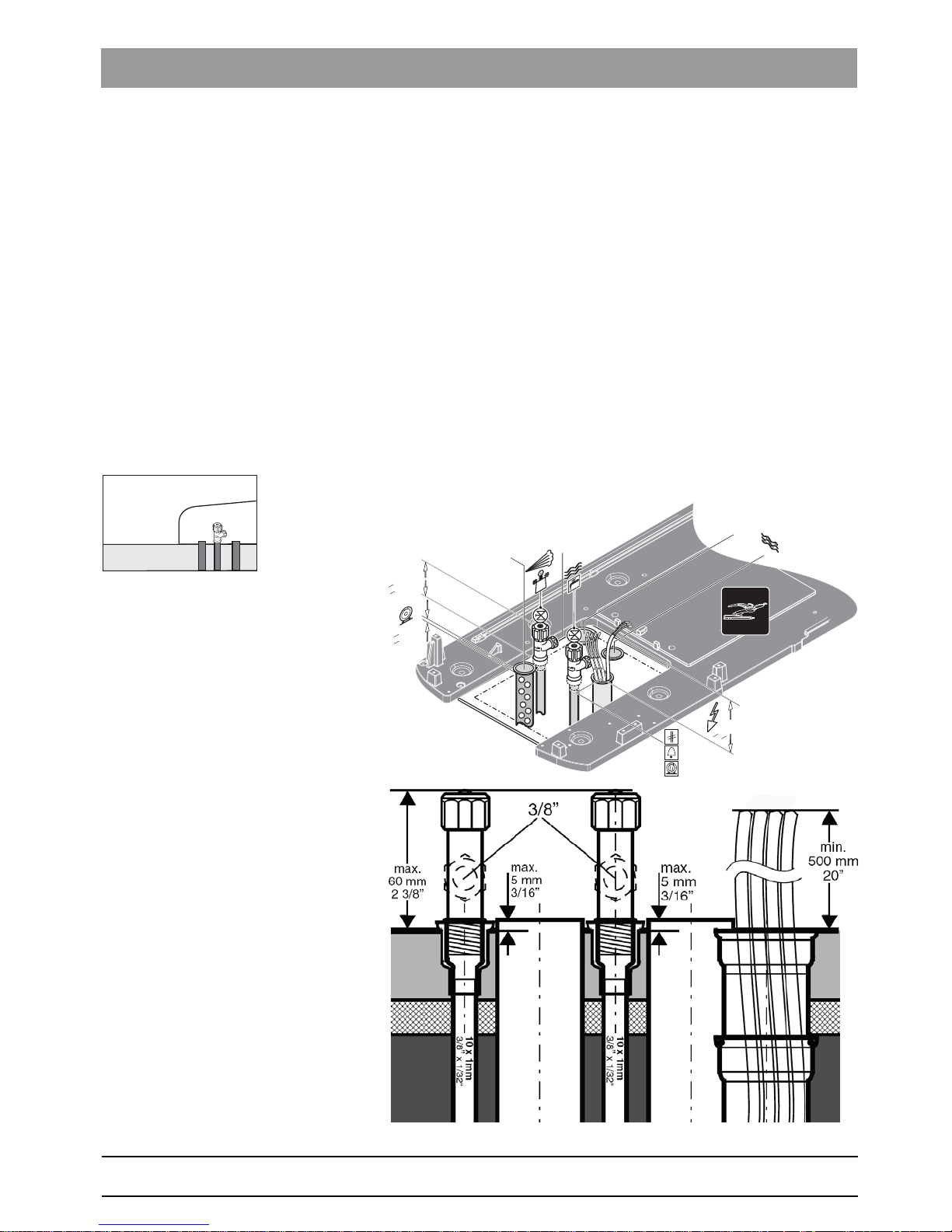
3.4.2 Installation of the supply line in the termination panel
Supply lines for Teneo, Sinius
✔ An installation template is available or was prepared.
1. Check the position of the supply lines against the installation template
as per the practice blueprint. Ensure that sufficient space is provided
between the lines and the walls; see "Scale 1:20". The center of the
hole in the floor must be 269 mm (10 5/8") from the foot of the
treatment center.
2. Lay the ends of the supply pipes, corner valves and lines as shown in
the illustrations.
ª The top edge of the corner valves for air and water must not project
more than 60 mm from the top edge of the floor.
ª The suction and drainage pipes must be flush with the top edge of the
floor (a deviation of +5 mm is permissible). The inner diameter of both
pipes is 36.5 mm.
ª The electric lines must project by at least 500 mm.
ª The supply lines are laid.
Ø 50 mm
Ø 36,5 mm
>500mm
>20“
< 3/16“
< 5mm
< 60mm
< 2 3/8“
Ø 36,5 mm
3/8“
Page 18
63 22 668 D3561
18 D3561.021.01.06.02 12.2014
3On-site installation Sirona Dental Systems GmbH
3.5Cleaning the air and water pipes Installation Requirements SINIUS / SINIUS CS / SINIUS TS
3.5
Cleaning the air and water pipes
Flushing the air and water pip es
NOTICE
Chips and other foreign materials could be flushed and/or blown into the
treatment center.
Metal chips can cause malfunctions of the pneumatic components. The
filters become clogged with foreign materials.
➢ During installation, ensure that no chips or other foreign materials
enter the lines.
➢ Flush the water lines.
➢ Blow out the air lines.
➢ Ensure that no more foreign materials can enter the lines after they
have been flushed or blown out.
10l
>30 sec
Versorgung durch den Fußboden
Supply through the floor
Alimentation à travers du plancher
Alimentación a través del suelo
Page 19

63 22 668 D3561
D3561.021.01.06.02 12.2014
19
Sirona Dental Systems GmbH 3On-site installation
Installation Requirements SINIUS / SINIUS CS / SINIUS TS 3.6Underfloor installation of the PC connections
bеЦдблЬ
3.6
Underfloor installation of the PC connections
Depending on the prevailing local conditions, the existing cable set can
be installed in the cable duct of an underfloor installation by an installer.
Cable channel No. 9 is used for this purpose, see Installation
template [ → 15].
Cable set for Sinius
Cable set for PC connection with HDMI and USB cable for camera
SiroCam AF / AF+, digital
REF 63 29 655
Cable break
Running cables to the PC
HYBRID PC connection ca bles
Lines L343 (USB repeater), L339 (Ethernet), L406 (HDMI) and protective
ground wire. For PCs without a HDMI output, the Audio line is also
required.
To prevent transmission interference, ensure that the cables are not
crossed.
Laying PC connection c ables, HYBRID
✔ A cable duct is laid from the treatment center to the location of the PC.
✔ Free length A of cables at the treatment center end: Length A = 600
mm
1. Pull the lines L343 (USB repeater), L339 (Ethernet), L406 (HDMI)
and protective ground wire of the treatment center through the cable
duct to the location of the PC C. For PCs without a HDMI output,
insert the Audio line. For the USB line L343 the TYPE A connector
must be on the PC side and the TYPE B connector on the chair side.
2. Save the accessory parts for final installation!
ª The preparation of the connection for the underfloor installation of the
PC is completed.
Minimum PC requireme nts
NOTICE
Electric lines are susceptible to breakages.
Any kinks or twists in the cables could damage their wires. You must
then replace such cables.
➢ Ensure that electrical lines do not become kinked or twisted.
C
A
IMPORTANT
Minimum requirements for PC
See document "Installation instructions and system requirements for PC
configuration," (REF 61 94 075 SIVISION digital.
Page 20

63 22 668 D3561
20 D3561.021.01.06.02 12.2014
4Dimensions, technical data Sirona Dental Systems GmbH
4.1SINIUS dimensions, scale bar 1:20 Installation Requirements SINIUS / SINIUS CS / SINIUS TS
4
Dimensions, technical data
4.1
SINIUS dimensions, scale bar 1:20
Dentist element with travel track
4.1.1 Dimensions of the treatment room
D
269
10 5/8”
1450
57”
1100
43 5/16”
2250
88 9/16”
410
16 1/8”
A
B
141
5 9/16”
600
23 5/8”
C
A Recommended distances from cabinet or wall.
B Center of the floor cut-out/installation area
C Minimum distance with tray and HELIODENT Plus
D Hazard warning: The lamp installed here and the tray and
HELIODENT Plus have a swivel range which exceeds the
specified distances!
Page 21

63 22 668 D3561
D3561.021.01.06.02 12.2014
21
Sirona Dental Systems GmbH 4Dimensions, technical data
Installation Requirements SINIUS / SINIUS CS / SINIUS TS 4.1SINIUS dimensions, scale bar 1:20
bеЦдблЬ
4.1.2 Side view
2000
78 3/4”
1580
62 1/4”
A
A
2150
84 5/8”
A
170
6 3/4”
380
15”
B
1226
48 1/4”
930
36 5/8”
1243
49”
Max. 957
37 5/8”
Min. 837
33”
778
30 5/8”
1480
58 1/4”
181
7 1/8”
Max. 800
31 1/2”
Min. 360
14 1/8”
291
11 1/2”
10°
C
30°
A Height and swivel range of the lamp
B LEDview
C Monitor on lamp support tube
Page 22

63 22 668 D3561
22 D3561.021.01.06.02 12.2014
4Dimensions, technical data Sirona Dental Systems GmbH
4.1SINIUS dimensions, scale bar 1:20 Installation Requirements SINIUS / SINIUS CS / SINIUS TS
4.1.3 Top view
Top view table
1191
46 7/8”
456
18”
355
14”
1059
41 11/16”
max.
2180
85 3/4”
801
31 1/2”
1735
68 1/4”
30°
269
10 5/8”
1930
76”
A
B
410
16 1/8”
42°
90°
max.
200
7 7/8”
14°
48°
180°
max.
2220
87 3/8”
1950
76 3/4”
D
C
1935
76 3/8”
90°
115°
A Double-jointed headrest: Length of treatment center with
patient height of 176cm and default program 2
B Double-jointed headrest: Maximum length of the treatment
center
C Motorized headrest: Length of treatment center with patient
height of 176cm and default program 2
D Motorized headrest: Maximum length of the treatment center
Page 23

63 22 668 D3561
D3561.021.01.06.02 12.2014
23
Sirona Dental Systems GmbH 4Dimensions, technical data
Installation Requirements SINIUS / SINIUS CS / SINIUS TS 4.1SINIUS dimensions, scale bar 1:20
bеЦдблЬ
4.1.4 Top view with options
181
7 1/8”
291
11 1/2”
E
D
750
29 1/2”
770
30 3/8”
750
29 1/2”
670
26 3/8”
600
23 5/8”
180
7”
C
85°
90°
300°
310°
A
B
A Tray
B LEDview
C Monitor on lamp support tube
D Projection of tray arm
E Projection of lamp arm
Page 24

63 22 668 D3561
24 D3561.021.01.06.02 12.2014
4Dimensions, technical data Sirona Dental Systems GmbH
4.1SINIUS dimensions, scale bar 1:20 Installation Requirements SINIUS / SINIUS CS / SINIUS TS
4.1.5 Size of the treatment room with HELIODENT Plus
269
10 5/8”
1450
57”
2250
88 9/16”
410
16 1/8”
A
B
141
5 9/16”
1360
53 1/2”
D
E
210°
F
C
600
23 5/8”
A Recommended distances from cabinet or wall.
B Center of the floor cut-out/installation area
C Minimum distance with tray and HELIODENT Plus
D Hazard warning: The lamp installed here and the tray and
HELIODENT Plus have a swivel range which exceeds the
specified distances!
E HELIODENT Plus wall adapter
F Support arm with HELIODENT Plus tube assembly
Page 25

63 22 668 D3561
D3561.021.01.06.02 12.2014
25
Sirona Dental Systems GmbH 4Dimensions, technical data
Installation Requirements SINIUS / SINIUS CS / SINIUS TS 4.1SINIUS dimensions, scale bar 1:20
bеЦдблЬ
4.1.6 Side view with HELIODENT Plus
1300
51 3/16”
2020
79 1/2”
1170
46”
660
26”
C
297
11 5/8”
1110
43 3/4”
281
11”
48
1 7/8”
343
13 1/2”
213
8 3/8”
50
2”
75
3”
A
B
A Recommended installation height for wall adapter: 1110 mm
(43 3/4“)
B Cable bushing for control line
C The control line between SINIUS and the wall adapter are
supplied (12.5 mm outer diameter, max. cable length 10 meters
(393”).
Page 26

63 22 668 D3561
26 D3561.021.01.06.02 12.2014
4Dimensions, technical data Sirona Dental Systems GmbH
4.2SINIUS CS dimensions, scale bar 1:20 Installation Requirements SINIUS / SINIUS CS / SINIUS TS
4.2
SINIUS CS dimensions, scale bar 1:20
Dentist element with swivel arms
4.2.1 Dimensions of the treatment room
1250
49 1/4”
1300
51 3/16”
2250
88 9/16”
410
16 1/8”
A
269
10 5/8”
B
141
5 9/16”
Pos. 1
Pos. 2
D
C
A Recommended distances from cabinet or wall.
B Center of the floor cut-out/installation area
C Hazard warning: The lamp, dentist element / with tray
(optional) and the HELIODENT Plus installed here have a
swivel range which exceeds the specified distances!
D The dentist element and the lamp can be installed either in
Position 1 or Position 2. (Not possible with HELIODENT Plus
on the lamp support tube)
Page 27

63 22 668 D3561
D3561.021.01.06.02 12.2014
27
Sirona Dental Systems GmbH 4Dimensions, technical data
Installation Requirements SINIUS / SINIUS CS / SINIUS TS 4.2SINIUS CS dimensions, scale bar 1:20
bеЦдблЬ
4.2.2 Side view
1226
48 1/4”
930
36 5/8”
1243
49”
Max. 800
31 1/2”
Min. 360
14 1/8”
Max. 1353
53 1/4”
Min. 967
38”
778
30 5/8”
181
7 1/8”
291
11 1/2”
Pos. 1
Pos. 2
D
D
2000
78 3/4”
1580
62 1/4”
A
A
2150
84 5/8”
A
170
6 3/4”
380
15”
B
10°
C
30°
A Height and swivel range of the lamp
B LEDview
C Monitor on lamp support tube
D Projection of the lamp arm in Position 1 and Position 2
Page 28

63 22 668 D3561
28 D3561.021.01.06.02 12.2014
4Dimensions, technical data Sirona Dental Systems GmbH
4.2SINIUS CS dimensions, scale bar 1:20 Installation Requirements SINIUS / SINIUS CS / SINIUS TS
4.2.3 Top view
Top view table
1275
50 1/4”
456
18”
355
14”
1059
41 11/16”
max.
200
7 7/8”
1935
76 3/8”
269
10 5/8”
180°
14°
48°
90°
115°
max.
2180
85 3/4”
1930
76”
A
B
max.
2220
87 3/8”
1950
76 3/4”
D
C
A Double-jointed headrest: Length of treatment center with
patient height of 176cm and default program 2
B Double-jointed headrest: Maximum length of the treatment
center
C Motorized headrest: Length of treatment center with patient
height of 176cm and default program 2
D Motorized headrest: Maximum length of the treatment center
Page 29

63 22 668 D3561
D3561.021.01.06.02 12.2014
29
Sirona Dental Systems GmbH 4Dimensions, technical data
Installation Requirements SINIUS / SINIUS CS / SINIUS TS 4.2SINIUS CS dimensions, scale bar 1:20
bеЦдблЬ
4.2.4 Top view with options
181
7 1/8”
A
C
B
291
11 1/2”
Pos. 1
Pos. 2
750
29 1/2”
770
30 3/8”
180
7”
85°
90°
300°
310°
A LEDview
B Monitor on lamp support tube
C Projection of the lamp arm in Position 1 and Position 2
Page 30

63 22 668 D3561
30 D3561.021.01.06.02 12.2014
4Dimensions, technical data Sirona Dental Systems GmbH
4.2SINIUS CS dimensions, scale bar 1:20 Installation Requirements SINIUS / SINIUS CS / SINIUS TS
4.2.5 Size of the treatment room with HELIODENT Plus
1360
53 1/2”
1250
49 1/4”
2250
88 9/16”
410
16 1/8”
A
269
10 5/8”
B
141
5 9/16”
D
E
210°
F
C
600
23 5/8”
A Recommended distances from cabinet or wall.
B Center of the floor cut-out/installation area
C Minimum distance with lamp and HELIODENT Plus
D Hazard warning: The lamp, dentist element / with tray
(optional) and the HELIODENT Plus installed here have a
swivel range which exceeds the specified distances!
E HELIODENT Plus wall adapter
F Support arm with HELIODENT Plus tube assembly
Page 31

63 22 668 D3561
D3561.021.01.06.02 12.2014
31
Sirona Dental Systems GmbH 4Dimensions, technical data
Installation Requirements SINIUS / SINIUS CS / SINIUS TS 4.2SINIUS CS dimensions, scale bar 1:20
bеЦдблЬ
4.2.6 Side view with HELIODENT Plus
1300
51 3/16”
2020
79 1/2”
1170
46”
660
26”
C
297
11 5/8”
1110
43 3/4”
281
11”
48
1 7/8”
343
13 1/2”
213
8 3/8”
50
2”
75
3”
A
B
A Recommended installation height for wall adapter: 1110 mm (43
3/4“)
B Cable bushing for control line
C The control line between SINIUS and the wall adapter are
supplied (12.5 mm outer diameter, max. cable length 10 meters
(393”).
Page 32

63 22 668 D3561
32 D3561.021.01.06.02 12.2014
4Dimensions, technical data Sirona Dental Systems GmbH
4.3SINIUS TS dimensions, scale bar 1:20 Installation Requirements SINIUS / SINIUS CS / SINIUS TS
4.3
SINIUS TS dimensions, scale bar 1:20
Dentist element as swivel table
4.3.1 Dimensions of the treatment room
1250
49 1/4”
1100
43 5/16”
2440
96 1/16”
450
17 3/4”
A
C
269
10 5/8”
B
181
7 1/8”
A Recommended distances from cabinet or wall.
B Center of the floor cut-out/installation area
C Hazard warning: The lamp, dentist element / with tray
(optional) and the HELIODENT Plus installed here have a
swivel range which exceeds the specified distances!
Page 33

63 22 668 D3561
D3561.021.01.06.02 12.2014
33
Sirona Dental Systems GmbH 4Dimensions, technical data
Installation Requirements SINIUS / SINIUS CS / SINIUS TS 4.3SINIUS TS dimensions, scale bar 1:20
bеЦдблЬ
4.3.2 Side view
1226
48 1/4”
930
36 5/8”
1243
49”
Max. 800
31 1/2”
Min. 360
14 1/8”
Max. 1270
50”
Min. 850
33 1/2”
778
30 5/8”
2000
78 3/4”
1580
62 1/4”
A
A
2150
84 5/8”
A
170
6 3/4”
380
15”
B
181
7 1/8”
10°
C
30°
A Height and swivel range of the lamp
B LEDview
C Monitor on lamp support tube
Page 34

63 22 668 D3561
34 D3561.021.01.06.02 12.2014
4Dimensions, technical data Sirona Dental Systems GmbH
4.3SINIUS TS dimensions, scale bar 1:20 Installation Requirements SINIUS / SINIUS CS / SINIUS TS
4.3.3 Top view
Top view table
160°
270°
180°
1651
65”
456
18”
355
14”
1059
41 11/16”
max.
200
7 7/8”
1935
76 3/8”
269
10 5/8”
180°
14°
48°
90°
115°
max.
2180
85 3/4”
1930
76”
A
B
max.
2220
87 3/8”
1950
76 3/4”
D
C
A Double-jointed headrest: Length of treatment center with
patient height of 176cm and default program 2
B Double-jointed headrest: Maximum length of the treatment
center
C Motorized headrest: Length of treatment center with patient
height of 176cm and default program 2
D Motorized headrest: Maximum length of the treatment center
Page 35

63 22 668 D3561
D3561.021.01.06.02 12.2014
35
Sirona Dental Systems GmbH 4Dimensions, technical data
Installation Requirements SINIUS / SINIUS CS / SINIUS TS 4.3SINIUS TS dimensions, scale bar 1:20
bеЦдблЬ
4.3.4 Top view with options
181
7 1/8”
C
291
11 1/2”
750
29 1/2”
770
30 3/8”
180
7”
C
85°
90°
300°
310°
B
A LEDview
B Monitor on lamp support tube
C Projection of the fixed dentist element support arm
Page 36

63 22 668 D3561
36 D3561.021.01.06.02 12.2014
4Dimensions, technical data Sirona Dental Systems GmbH
4.3SINIUS TS dimensions, scale bar 1:20 Installation Requirements SINIUS / SINIUS CS / SINIUS TS
4.3.5 Size of the treatment room with HELIODENT Plus
1250
49 1/4”
2440
96 1/16”
450
17 3/4”
A
D
269
10 5/8”
B
181
7 1/8”
1360
53 1/2”
E
210°
F
600
23 5/8”
C
A Recommended distances from cabinet or wall.
B Center of the floor cut-out/installation area
C Minimum distance with lamp and HELIODENT Plus
D Hazard warning: The lamp, dentist element / with tray
(optional) and the HELIODENT Plus installed here have a
swivel range which exceeds the specified distances!
E HELIODENT Plus wall adapter
F Support arm with HELIODENT Plus tube assembly
Page 37

63 22 668 D3561
D3561.021.01.06.02 12.2014
37
Sirona Dental Systems GmbH 4Dimensions, technical data
Installation Requirements SINIUS / SINIUS CS / SINIUS TS 4.3SINIUS TS dimensions, scale bar 1:20
bеЦдблЬ
4.3.6 Side view with HELIODENT Plus
1300
51 3/16”
2020
79 1/2”
1170
46”
660
26”
C
297
11 5/8”
1110
43 3/4”
281
11”
48
1 7/8”
343
13 1/2”
213
8 3/8”
50
2”
75
3”
A
B
A Recommended installation height for wall adapter: 1110 mm (43
3/4“)
B Cable bushing for control line
C The control line between SINIUS and the wall adapter are
supplied (12.5 mm outer diameter, max. cable length 10 meters
(393”).
Page 38

63 22 668 D3561
38 D3561.021.01.06.02 12.2014
4Dimensions, technical data Sirona Dental Systems GmbH
4.4Mounting plates Installation Requirements SINIUS / SINIUS CS / SINIUS TS
4.4
Mounting plates
Adapter plate for Teneo, Sinius
Adapter plate
If the dental treatment center is being installed as a replacement for an
M1 previously installed at this location, an adapter plate is available for
this purpose. You can use the existing drill holes for fastening. Two
additional drill holes are required only in the area of the water unit. The
treatment center is screwed onto the steel plate using M10 screws.
The adapter plate also must be used if the unevenness of the floor
exceeds 2 mm in the vicinity of the base plate.
Note: If a C-Line unit (e.g. C2
+
, M1+ ) was previously installed, the
fastening drill holes must be re-drilled.
Adapter plate thickness: 12 mm
Drilling with floor (7x)
REF 63 07 511
Demo plate for Teneo, Sinius
Page 39

63 22 668 D3561
D3561.021.01.06.02 12.2014
39
Sirona Dental Systems GmbH 4Dimensions, technical data
Installation Requirements SINIUS / SINIUS CS / SINIUS TS 4.4Mounting plates
bеЦдблЬ
Demonstration chair plate
For floors which do not permit permanent connection of the unit (e.g.
demo operation at a trade show, floor heating), installation on a steel
demo plate is possible.
The treatment center is screwed onto the steel plate using M10 screws.
If the demo chair plate is permanently installed and whenever it is used
for medical purposes, is must be screwed firmly to points C on the floor
using two screws.
Demonstration plate thickness: 10 mm
REF 63 08 717
Page 40

63 22 668 D3561
40 D3561.021.01.06.02 12.2014
4Dimensions, technical data Sirona Dental Systems GmbH
4.5Information on planning for the practice Installation Requirements SINIUS / SINIUS CS / SINIUS TS
4.5
Information on planning for the practice
The following file(s) for practice planning are available for download in the
dealer area of the Sirona website under DOWNLOADS => CAAD files:
● PDF file with print symbol - for to-scale printing on paper or adhesive
film
● CAAD file(s) - for professional implementation planning with 2D/3D
CAAD systems
Page 41

63 22 668 D3561
D3561.021.01.06.02 12.2014
41
Sirona Dental Systems GmbH 4Dimensions, technical data
Installation Requirements SINIUS / SINIUS CS / SINIUS TS 4.6Technical data
bеЦдблЬ
4.6
Technical data
Model designation, power rati ng s
Unit classifications, without HF surgery
Mode of operation
Model designation: SINIUS / SINIUS CS / SINIUS TS
Power connection: 100 - 230 V AC ± 10%
50/60 Hz
Nominel current: 2.2 A at 230 V
4.35 A at 115 V
5.0 A at 100 V
also max. 6 A for external devices
Type of earthing system: TN-C-S system or TN-S system
(according to IEC 60364-1)
Overvoltage category: 2 acc. to IEC 60664-1
Average power consumption
(for dimensioning an air
conditioning system):
0.25 kW
Power consumption in
Standby mode:
3 W (without internal mini PC)
Main building fuse: Automatic circuit breaker type B
100 – 115 V AC: 20 A slow burn
230 V AC: 16 A slow burn
Protection class: Class I equipment
Device class in accordance
with Directive 93/42/EEC:
Class IIa equipment
Degree of protection against
electric shock:
Type B applied parts
Except SiroCam AF intraoral camera.
This is
Applied part type BF
Degree of protection against
ingress of water:
Ordinary equipment (without protection
against ingress of water)
The foot control has an IP X1 degree of
protection against liquids (drip-proof).
Mode of operation Continuous operation with intermittent
loading corresponding to the dental
mode of working.
Drive motors for chair operation:
intermittent use, max. 2 minutes on and
18 minutes off
Permanently connected unit. Operation
is not permitted in mobile vehicles.
Page 42

63 22 668 D3561
42 D3561.021.01.06.02 12.2014
4Dimensions, technical data Sirona Dental Systems GmbH
4.6Technical data Installation Requirements SINIUS / SINIUS CS / SINIUS TS
Operating and transport condit i on s
Approval and year of m anufacture
Transport and storage
conditions:
Temperature: -40 °C – +70 °C
(-40 °F – 158 °F)
Relative humidity: 10% – 95%
Air pressure: 500 hPa – 1,060 hPa
Operating conditions: Ambient temperature: 10 °C – 40 °C (50
°F – 104 °F)
Relative humidity: 30% – 85%
no condensation
Air pressure: 700 hPa – 1,060 hPa
Installation location: ≤ 3000 m above sea level
This treatment center is not suitable for
operation in areas subject to explosion
hazards.
Pollution degree: 2 acc. to IEC 60664-1
-40
+70
1060
500
95
10
+10
+40
1060
700
85
30
Tests/Approvals: See "Standards/Approvals“ [ → 44].
Year of manufacture:
(on the rating plate)
USB port: corresponds to USB 2.0 standard
20XX
Page 43

63 22 668 D3561
D3561.021.01.06.02 12.2014
43
Sirona Dental Systems GmbH 4Dimensions, technical data
Installation Requirements SINIUS / SINIUS CS / SINIUS TS 4.6Technical data
bеЦдблЬ
Weight, packaging, pressu res
Foot switch wireless interface
Foot control wireless interface, worldwide
Minimum PC requireme nts
Weight (with packaging and
accessories/without
packaging):
SINIUS
dentist element, assistant element: 63 kg
/ 42 kg
SINIUS CS dentist element:
55 kg / 40 kg
SINIUS TS dentist element:
45 kg / 29.5 kg
SINIUS CS/TS assistant element:
15 kg / 10 kg
Water unit: 80 kg / 66 kg
Chair: 116 kg / 91 kg
Upholstery: 8.5 kg / 5.5 kg
Dimensions of the packaging SINIUS
dentist element, assistant element: 126
cm x 72 cm x 75 cm
SINIUS CS dentist element: 136 cm x 86
cm x 65 cm
SINIUS TS dentist element: 154 cm x 57
cm x 80 cm
SINIUS CS/TS assistant element: 88
cm x 35 cm x 74 cm
Water unit: 83 cm x 69 cm x 121 cm
Chair: 153 cm x 66 cm x 88 cm
Upholstery: 80 cm x 60 cm x 36 cm
Accessories (1 or 2 packages):
120 cm x 80 cm x 44 cm or 68 cm
Supply pressures (min./
max.):
Air: 5.5 / 7.5 bar
Water 2.5 / 6 bar
Suction air: p
u
≤ 0.18 bar; ≥ 500 l/min
Water flow rate: Water absorption max. 3 l/min
Residual water max. 3 l/min
Model designation: nanoLOC AVR
Frequency: 2.4 GHz – 2.4835 GHz (ISM band)
Transmitting power: < 2 mW (short-range device)
Modulation type: MDMA
Range: approx. 10 m
Approval: See "Standards/Approvals“ [ → 44].
IMPORTANT
Minimum requirements for PC
See document "Installation instructions and system requirements for PC
configuration," (REF 61 94 075 SIVISION digital.
Page 44

63 22 668 D3561
44 D3561.021.01.06.02 12.2014
4Dimensions, technical data Sirona Dental Systems GmbH
4.7Standards/Approvals Installation Requirements SINIUS / SINIUS CS / SINIUS TS
4.7
Standards/Approvals
Compliance with standards, without HF surgery
The treatment center SINIUS® complies with the following standards,
among others:
● IEC 60601-1 (electrical and mechanical safety plus software
reliability)
● IEC 60601-1-2 (electromagnetic compatibility)
● IEC 60601-1-6 / IEC 62366 (usability)
● IEC 62304 (software process)
● ISO 6875 (patient chair)
● ISO 7494-1 (dental treatment devices)
● ISO 7494-2 (dental treatment devices, water and air supply)
● ISO 9680 (operating light)
● ISO 11143 (amalgam separator), see also below
(provided amalgam separator option is available)
● EN 1717 (connection to the drinking water system), see also below
and chapter "Connection to the public drinking water supply" [ → 11]
Original language of this document: German
CE mark, general
This product bears the CE marking in accordance with the provisions of
Council Directive 93/42/EEC of June 14, 1993 concerning medical
devices.
RoHS Directive
The treatment center complies with the requirements of the RoHS
Directive 2011/65/EU.
Ü and AFNOR marks of the amalgam separator, also for Fran ce
The amalgam separator achieves a separation efficiency of >95%. The
unit thus fulfills the requirements of ISO 11143.
Separating procedure type 1: Centrifugal system
The amalgam separator is approved by the German Institute for
Structural Engineering (DIBt) and by the AFNOR (France).
DVGW-certified safe conn ection for Germany, disinfection system
When equipped with a disinfection system, the treatment center complies
with the technical rules and requirements on safety and hygiene for
connection to the public drinking water supply. The unit is certified
according to the requirements of the DVGW (German Gas and Water
Association). It is intrinsically safe in accordance with worksheet W540.
The unit thus fulfills the requirements of EN 1717, see also the chapter
entitled "Connection to the public drinking water supply" [ → 11].
BELG AQUA for Belgium
This unit meets the requirements of BELGAQUA and may therefore be
connected to the public drinking water supply in Belgium.
0123
SIRONA
Dental Systems
GmbH
64625 Bensheim
Fabrikstrasse 31
Z-64.1-14
Page 45

63 22 668 D3561
D3561.021.01.06.02 12.2014
45
Sirona Dental Systems GmbH 4Dimensions, technical data
Installation Requirements SINIUS / SINIUS CS / SINIUS TS 4.7Standards/Approvals
bеЦдблЬ
ATS for Australia
This unit meets the requirements of ATS and may therefore be connected
to the public drinking water supply in Australia.
CE mark of the wireless foot control
The wireless modules in the wireless foot control and in the treatment
center meet the requirements of the R&TTE directive 1999/5/'EC.
Standards:
● EN 60950-1
● EN 301489-1, EN 301489-17, EN 300328
FCC for wireless foot control
The modules meet the requirements of the Federal Communications
Commission (Part 15 of the FCC Rules).
FCC ID: SIFNANOLOCAVR0108
Industry Canada for wireles s foot control
Industry Canada The modules meet the requirements of Industry Canada (RSS210).
IC: 7654A-nanoLOCAVR
The current approvals of the wireless foot control are listed on the rating
label on the underside of the wireless foot control.
Product name is a registered trademark
SINIUS® is a registered trademark of Sirona Dental Systems GmbH.
WaterMark
TM
ATS 5200.104
Certificate No. 21208
Page 46

63 22 668 D3561
46 D3561.021.01.06.02 12.2014
5Electromagnetic compatibility Sirona Dental Systems GmbH
5.1Accessories Installation Requirements SINIUS / SINIUS CS / SINIUS TS
5
Electromagnetic compatibility
EMC in accordance with IEC
Observance of the following information is necessary to ensure safe
operation regarding EMC aspects.
SINIUS / SINIUS CS / SINIUS TS complies with the requirements for
electromagnetic compatibility (EMC) according to IEC 60601-1-2.
SINIUS / SINIUS CS / SINIUS TS is hereinafter referred to as "UNIT".
5.1
Accessories
Making the PC connection
The required interface cables can be ordered from Sirona.
Interface cables
Accessories approved b y Sirona
The UNIT may only be operated with accessories and spare parts
approved by Sirona. Unapproved accessories and spare parts may lead
to an increased emission or to a reduced immunity to interference.
The UNIT should not be operated in the immediate vicinity of other
devices. If this proves to be unavoidable, the UNIT should be monitored
to ensure that it is operating properly.
Accessories for EMC me asurement
Accessories for EMC measurement
The EMC measurements were performed with the following PCs:
Designation of the interface cables Supplier
HDMI cable, 10 m (L406) Sirona
USB 2 cable with repeater, 10 m (L343),
connectors: Type A, Type B
Sirona
Ethernet cable, 10 m (L339) Sirona
Audio cable, 10 m Sirona
2nd protective ground wire, 2.5 mm2, 10 m
Sirona
PC as peripheral device for checking
the interfaces with:
Fujitsu Siemens Pentium 4 Fujitsu Siemens ESPRIMO
Mini PC MPC D1007
PC equipment:
Processor Intel Pentium 4; 3 GHz Intel Core i3; 2.13GHz
RAM 512 MB DDR 266 2 GB
Graphics card NVIDIA GeForce 7300 LE Intel HD Graphics
Hard disk drive ST3116085AS Hitachi HTS 545016)
Keyboard PS/2 HID USB
Mouse Logitech PS/2 Fujitsu OPT USB
Interfaces: 1 x COM; 1 x LPT; 4 x USB 1 x LAN; 4 x USB, 1 x HDMI
Software: SIDEXIS XG Video, Version 2.3
SIUCOM plus (Sirona)
SIDEXIS XG Video, Version 2.3
SIUCOM plus (Sirona)
Operating system Microsoft XP Professional Version
2002 SP 3
Microsoft Windows 7 Professional
Page 47

63 22 668 D3561
D3561.021.01.06.02 12.2014
47
Sirona Dental Systems GmbH 5Electromagnetic compatibility
Installation Requirements SINIUS / SINIUS CS / SINIUS TS 5.2Electromagnetic emission
bеЦдблЬ
5.2
Electromagnetic emission
The UNIT is intended for operation in the electromagnetic environment
specified below.
The customer or user of the UNIT should make sure that it is used in such
an environment.
Emission measurement Conformity Electromagnetic environment - guidelines
RF emissions according to CISPR 11 Group 1 The UNIT uses RF energy only for its internal
function. Therefore, its RF emissions are very low
and are not likely to cause any interference in
nearby electronic equipment.
RF emissions according to CISPR 11 Class B The UNIT is intended for use in all facilities,
including residential areas and in any facilities
connected directly to a public power supply
providing electricity to buildings used for residential
purposes.
Harmonics
according to IEC 61000-3-2
Class A
Voltage fluctuations / flicker according
to IEC 61000-3-3
coincides
Page 48

63 22 668 D3561
48 D3561.021.01.06.02 12.2014
5Electromagnetic compatibility Sirona Dental Systems GmbH
5.3Interference immunity Installation Requirements SINIUS / SINIUS CS / SINIUS TS
5.3
Interference immunity
The UNIT is intended for operation in the electromagnetic environment
specified below.
The customer or user of the UNIT should make sure that it is used in such
an environment.
Interference immunity
tests
IEC 60601-1-2 test
level
Compliance level Electromagnetic environment -
guidelines
Electrostatic discharge
(ESD) according to IEC
61000-4-2
± 6 KV contact
discharge
± 8 KV air discharge
± 6 KV contact
discharge
± 8 KV air discharge
Floors should be made of wood or
concrete or finished with ceramic
tiling. If the floor is covered with
synthetic material, the relative
humidity should be at least 30%.
Electrical fast transient/
burst according to
IEC 61000-4-4
± 1kV for input and
output lines
± 2 kV for power supply
lines
± 1 kV for input and
output lines
± 2 kV for power supply
lines
The quality of the line power supply
should be that of a typical
commercial or hospital environment.
Surge voltages
according to IEC 610004-5
± 1 kV differential mode
± 2 kV common mode
voltage
± 1 kV differential mode
± 2 kV common mode
voltage
The quality of the line power supply
should be that of a typical
commercial or hospital environment.
Voltage dips, short
interruptions and
variations of the power
supply
according to IEC 610004-11
<5% U
T
for ½ period
(>95% dip of U
T
)
40% U
T
for 5 periods
(60% dip of U
T
)
70% U
T
for 25 periods
(30% dip of U
T
)
<5% U
T
for 5sec.
(>95% dip of U
T
<5% UT for ½ period
(>95% dip of U
T
)
40% U
T
for 5 periods
(60% dip of U
T
)
70% U
T
for 25 periods
(30% dip of U
T
)
<5% U
T
for 5sec.
(>95% dip of U
T
The quality of the line power supply
should be that of a typical
commercial or hospital environment.
If the user of the UNIT requires it to
continue functioning following
interruptions of the power supply, it is
recommended to have the UNIT
powered by an uninterruptible power
supply or a battery.
Magnetic field of power
frequencies (50/60 Hz)
according to IEC 610004-8
3 A/m 3 A/m Power frequency magnetic fields
should be at levels characteristic of a
typical location in a typical
commercial or hospital environment.
Note: U
T
is the AC supply voltage prior to application of the test level.
Portable and mobile radio equipment
must not be used within the
recommended working clearance
from the UNIT and its cables, which
is calculated based on the equation
suitable for the relevant transmission
frequency.
Recommended working clearance:
Page 49

63 22 668 D3561
D3561.021.01.06.02 12.2014
49
Sirona Dental Systems GmbH 5Electromagnetic compatibility
Installation Requirements SINIUS / SINIUS CS / SINIUS TS 5.3Interference immunity
bеЦдблЬ
1. The higher frequency range applies at 80 MHz and 800 MHz.
2. The field strengths of fixed transmitters, such as base stations of
radiotelephones and mobile agricultural radio broadcast services,
amateur radio stations, AM and FM radio broadcast and TV
broadcast cannot be predicted theoretically with accuracy. A site
survey is recommended to assess the electromagnetic environment
due to fixed RF transmitters. If the measured field strength in the
location in which the UNIT is used exceeds the applicable RF
compliance level above, the UNIT should be observed to verify
normal operation. If unusual performance characteristics are
observed, it may be necessary to take additional measures such as
reorientation or repositioning of the UNIT.
3. Over the frequency range 150kHz to 80 MHz, field strengths should
be less than 3 V/m.
Conducted RF
disturbance
IEC 61000-4-6
3 V
eff
150 kHz to 80 MHz
1
3 V
eff
d= [1,2] √P
Radiated RF interference
IEC 61000-4-3
3 V/m
80 MHz - 800 MHz
1
3 V/m
800 MHz - 2.5 GHz
1
3 V
eff
3 V
eff
d= [1,2] √P
at 80 MHz - 800 MHz
d= [2,3] √P
at 800 MHz - 2.5 GHz
with P as the power rating of the
transmitter in watts (W) according to
the transmitter manufacturer's
specifications and d as
recommended safety distance in
meters (m).
Field strengths from fixed RF
transmitters, as determined by an
electromagnetic site survey
2
should
be less than the compliance level
3
in
each frequency range.
Interference is possible in the vicinity
of equipment bearing the following
graphic symbol.
Interference immunity
tests
IEC 60601-1-2 test
level
Compliance level Electromagnetic environment -
guidelines
Page 50

63 22 668 D3561
50 D3561.021.01.06.02 12.2014
5Electromagnetic compatibility Sirona Dental Systems GmbH
5.4Working clearances Installation Requirements SINIUS / SINIUS CS / SINIUS TS
5.4
Working clearances
Recommended working clearances
between portable and mobile HF
communication devices and the UNIT
The UNIT is intended for operation in an electromagnetic environment,
where radiated RF interference is checked. The customer or the user of
the UNIT can help prevent electromagnetic interference by maintaining a
minimum distance between portable and mobile RF communications
equipment (transmitters) and the UNIT - depending on the maximum
output power of the communication device, as shown below.
The recommended safety distance d in meters (m) can be determined for
transmitters, whose maximum power rating is not specified in the above
table, using the equation that belongs to the corresponding column,
wherein P is the maximum power rating of the transmitter in watts (W)
according to the transmitter manufacturer.
Note 1
The higher frequency range applies at 80 MHz and 800 MHz.
Note 2
These guidelines may not apply in all cases. The propagation of
electromagnetic waves is influenced by their absorption and reflection by
buildings, objects and persons.
Power rating of the transmitter
[W]
Working clearance according to transmission frequency [m]
150 kHz - 80 MHz 80 MHz - 800 MHz 800 MHz - 2.5 GHz
d= [1,2] √P d= [1,2] √P d= [2,3] √P
0.01 0.12 0.12 0.23
0.1 0.38 0.38 0.73
1 1.2 1.2 2.3
10 3.8 3.8 7.3
100 12 12 23
Page 51

63 22 668 D3561
D3561.021.01.06.02 12.2014
51
Sirona Dental Systems GmbH 5Electromagnetic compatibility
Installation Requirements SINIUS / SINIUS CS / SINIUS TS 5.5Foot control wireless interface
bеЦдблЬ
5.5
Foot control wireless interface
Insofar as the treatment center is equipped with a foot control, one
wireless module each must be installed in the foot control and in the base
of the chair of the treatment center. These modules transmit the foot
control signals.
Wireless module in the wireless foot control and in the treatment
center
Foot control wireless interface, worldwide
CAUTION
Interference with the wireless transmission
This wireless transmission may cause interference with or be disturbed
by other radio services.
Model designation: nanoLOC AVR
Frequency: 2.4 GHz – 2.4835 GHz (ISM band)
Transmitting power: < 2 mW (short-range device)
Modulation type: MDMA
Range: approx. 10 m
Approval: See "Standards/Approvals“ [ → 44].
Page 52

63 22 668 D3561
52 D3561.021.01.06.02 12.2014
6Checklist Sirona Dental Systems GmbH
6.1Installation site Installation Requirements SINIUS / SINIUS CS / SINIUS TS
6
Checklist
6.1
Installation site
We recommend performing an inspection of the circumstances on location at least 4 weeks prior to installation. The
checklist should help you when doing this.
This can help ensure a smooth procedure on the day that the SINIUS is actually installed.
Installation location:
● Installation location:
● Unit location:
● Building number:
● Room name/number:
Page 53

63 22 668 D3561
D3561.021.01.06.02 12.2014
53
Sirona Dental Systems GmbH 6Checklist
Installation Requirements SINIUS / SINIUS CS / SINIUS TS 6.2Construction requirements
bеЦдблЬ
6.2
Construction requirements
Electrical connections for Teneo, Sinius
Uneven floors for Teneo, Sinius
Connections: Media (see On-site installation [ → 9]) ☑
● Water supply
Pipe 10x1 mm, corner valve outlet 3/8"
☐
● Compressed air supply line
Pipe 10x1 mm, corner valve outlet 3/8"
☐
● Suction line
DN 40 HT-PP ISO 8283-3, inner diameter 36.5 mm
☐
● Water drainage
DN 40 HT-PP ISO 8283-3, inner diameter 36.5 mm
☐
● Installation pipe (power supplies)
min. DN 40 HT-PP ISO 8283-3, inner diameter 40 mm
☐
● Installation pipe (IT)
DIN 40 HT-PP ISO 8283-3 (or corresponding flat conduit)
☐
Connections: Electrical (see On-site installation [ → 9]) ☑
● Power cable: 3 x 1.5 mm
²
☐
● Type B automatic circuit breaker
230 V AC, 16 A slow-blow or
● Type B automatic circuit breaker
100-115 V AC, 20 A slow-blow
☐
☐
● Suction machine control cable and call cable: 3 x 1.5 mm
²
☐
● Wireless systems in 2.4 GHz frequency range available?
(e.g. room monitoring systems, video transmitters, etc.)
☐ Yes ☐ No
● If yes, this may damage the wireless foot control.
Please consult our Product Service team.
Uneven floors: Mounting plates (see Mounting plates [ → 38]) ☑
● No plate required (unevenness max. 2 mm, shimming plates can be used) ☐
● Adapter plate, REF 63 07 511 ☐
● Demo plate (demo operation at a trade show), REF 63 08 717 ☐
● Load capacity of the floor is indicated (pressure and tensile loads). ☐
● The treatment center can be safely anchored in the load-bearing structure (concrete/wood;
NOT screed).
☐
Page 54

63 22 668 D3561
54 D3561.021.01.06.02 12.2014
6Checklist Sirona Dental Systems GmbH
6.3IT hardware Installation Requirements SINIUS / SINIUS CS / SINIUS TS
6.3
IT hardware
Mode of operation for Teneo, Sinius
PC system requirements
SINIUS monitor
Mode of operation ☑
● Stand-alone solution (mini PC required in the base of the chair) ☐
● PC in treatment room ☐
PC system requirements: ☑
IT hardware and software requirements are described in the document "Installation notes and
system requirements for PC configuration",
(REF 61 94 075) SIVISION digital
☐
IMPORTANT!
Please be aware that any deviations may cause malfunctions in camera mode. For further details,
see document "Installation instructions and system requirements for PC configuration", (REF 61
94 075) SIVISION digital.
Page 55

63 22 668 D3561
D3561.021.01.06.02 12.2014
55
Sirona Dental Systems GmbH 6Checklist
Installation Requirements SINIUS / SINIUS CS / SINIUS TS 6.4Network
bеЦдблЬ
6.4
Network
Network: ☑
● The entire network should be equipped with 100 MBit Ethernet.
● - Cat 5
- Cat 6
☐
☐
☐ 10Mbps
☐ 100Mbps
● Network connection for SINIUS available. ☐
● Network connection for external PC available. ☐
IMPORTANT!
The use of routers between SINIUS and the treatment center PC must be avoided.
● Network configuration plan available. ☐
● Network jacks have been certified. ☐
● Network certificate present. ☐
● Network installation company. ☐
● Remarks/Tasks:
Page 56

63 22 668 D3561
56 D3561.021.01.06.02 12.2014
6Checklist Sirona Dental Systems GmbH
6.5Data processing Installation Requirements SINIUS / SINIUS CS / SINIUS TS
6.5
Data processing
IP addresses/firewall:
● TCP/IP address range: _____ . _____. _____ . _____ - _____ . _____ . _____ . _____
● Subnet mask: _____ . _____ . _____ . ____
● Are addresses already defined/present? ☐ Yes ☐ No
● Is there a DHCP server (dynamic TCP/IP address assignment)? ☐ Yes ☐ No
NOTICE!
A static address should be assigned for the SINIUS.
It must not lie in the dynamic address range!
● SINIUS: _____ . _____ . _____ . ____
● Internal PC: _____ . _____ . _____ . ____
● External PC: _____ . _____. _____ . _____ - _____ . _____ . _____ . _____
● Standard gateway: _____ . _____ . _____ . ____
● Antivirus software available? ☐ Yes
Name:
☐ No
● Is a firewall installed?
Software or hardware firewall?
☐ Yes
☐ SW
☐ HW
☐ No
● Remarks/Tasks:
Practice administration programs:
● Are connections to the practice administration programs, etc. installed or
planned?
☐ Yes ☐ No
● If so, which system (manufacturer + name)?
● Remarks/Tasks:
Page 57

Page 58

tЙ=кЙлЙкоЙ=нЬЙ=кбЦЬн=нз=г~вЙ=~еу=~днЙк~нбзел=пЬбЕЬ=г~у=ДЙ=кЙимбкЙЗ=ЗмЙ=нз=нЙЕЬебЕ~д=бгйкзоЙгЙенлK
«=pбкзе~=aЙен~д=pулнЙгл=dгДe=OMNQ pйк~ЕЬЙW ЙеЦдблЕЬ mкбенЙЗ=бе=dЙкг~еу
aPRSNKMONKMNKMSKMO NOKOMNQ ûKJkêKW= NNV=VSS
pбкзе~=aЙен~д=pулнЙгл=dгДe
áå=íÜÉ=rp^W
c~Дкбвлнк~≈Й=PN
aJSQSOR=_ЙелЬЙбг
dÉêã~åó
пппKлбкзе~KЕзг
pбкзе~=aЙен~д=pулнЙгл=ii`
QUPR=pбкзе~=aкбоЙI=pмбнЙ=NMM
`Ь~кдзннЙI=k`=OUOTP
rp^
lêÇÉê=kç
SP=OO=SSU=aPRSN
 Loading...