

Page 1
ebiflabkq=ap
j~бенЙе~еЕЙ=fелнкмЕнбзел
Page 2

Maintenance Instructions Sirona Dental Systems GmbH
ATTENTION!
Adequate lead proofing of room and operator position is
essential.
Since these requirements vary from state to state it is the
assembler's / installer's responsibility that all local radiation
safety requirements are met.
2 41 62 983 D 3202.101.01.06.02
Page 3
Sirona Dental Systems GmbH Maintenance Instructions
General
In order to ensure in compliance with the DHHS requirements the HELIODENT®DS must be maintained
annually following date of installation. It is the responsibility of the user to ensure that the equipment is maintained in accordance with the manufacturer's recommended Maintenance Instructions to ensure compliance with the Federal Performance Standard.
The manufacturer and the assembler/installer are not responsible for disturbances in operation when the
equipment is not used in accordance with the operating instructions.
The maintenance inspection and consequent service must be accomplished by a skilled technician.
Neither the inspection nor service is part of the equipment warranty.
Technical instructions required
Operating Instructions and Service Manual
Instruments required
1. Digital multimeter model FLUKE 8000 A, or equivalent
Accuracy: AC voltage ± 0.5% of reading plus 1 digit
DC voltage ± 0.1% of reading plus 2 digits
DC current ± 0.3% of reading plus 1 digit
2. Electromechanical pulse counter,
model KESSLER ELLIS KT 203 ±1 pulse, or equivalent
CAUTION RADIATION
Observe radiation protection guidelines as outlined in the Operating Instructions!
ESD
CAUTION Technician!
PC-boards are fitted with electronic components sensitive to electrostatic discharge (ESD).
Electrostatic discharge is unavoidable due to friction of clothing, carpeting etc.
ATTENTION
To prevent damage of electronic components do not touch same.
Discharge your electrostatic energy by touching a grounded point.
Always handle circuit boards by the edge of same.
List of Contents
. . . . . . . . . . . . . . . . . . . . . . . . . . . . . . . . . . . . . . . . . . . . . . . . . . . . . . . . . . . . . . . . . . . . . . . . . . . . . . . Page
General . . . . . . . . . . . . . . . . . . . . . . . . . . . . . . . . . . . . . . . . . . . . . . . . . . . . . . . . . . . . . . . . . . . . . . . . . . . 3
Visual Check . . . . . . . . . . . . . . . . . . . . . . . . . . . . . . . . . . . . . . . . . . . . . . . . . . . . . . . . . . . . . . . . . . . . . . . 4
Light Indicators at the Multitimer Control Panel . . . . . . . . . . . . . . . . . . . . . . . . . . . . . . . . . . . . . . . . . . . . . 5
Tube Current Verification . . . . . . . . . . . . . . . . . . . . . . . . . . . . . . . . . . . . . . . . . . . . . . . . . . . . . . . . . . . . . . 6
Exposure Time Verification . . . . . . . . . . . . . . . . . . . . . . . . . . . . . . . . . . . . . . . . . . . . . . . . . . . . . . . . . . . . 7
Verification of the Exposure Button . . . . . . . . . . . . . . . . . . . . . . . . . . . . . . . . . . . . . . . . . . . . . . . . . . . . . . 8
Verification of the Object Selector Switch . . . . . . . . . . . . . . . . . . . . . . . . . . . . . . . . . . . . . . . . . . . . . . . . . 9
Mechanical Adjustments (if required) . . . . . . . . . . . . . . . . . . . . . . . . . . . . . . . . . . . . . . . . . . . . . . . . . . . . 10
Yearly Maintenance Checklist . . . . . . . . . . . . . . . . . . . . . . . . . . . . . . . . . . . . . . . . . . . . . . . . . . . . appendix
41 62 983 D 3202.101.01.06.02 3
Page 4
Maintenance Instructions Sirona Dental Systems GmbH
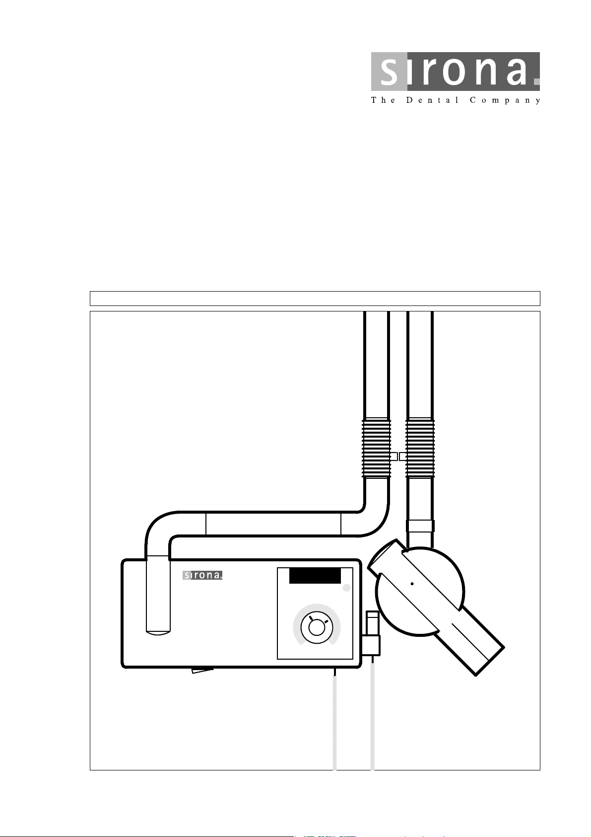
Röhre / Tube
Siemens SR 60 / 70 / 7 L
Cone / Tube
Model-No. 33 14 742 D 3302
Serial-No
This product complies with DHHS
regulations 21 CFR Subchapter J
applicable at date of manufacture.
Date of
manufacture:
Siemens Aktiengesellschaft
Wittelsbacherplatz 2
D-80333 München Germany
Model-
46 81 974 D 3302
No.
Serial-
No.
Model-
46 84 606 D 3302
No.
Serial-
No.
MADE IN GERMANY
12”
Model-No. 33 43 741 V 1034
Serial-No. . . . . . . . . . . . . . .
0.7 IEC 336 / 82
or
Röhre / Tube
Petrick P470/6.30/12G
Model-No. 60 91 651 D3302
Serial-No. . . . . . . . . . . . . . .
0.4 IEC 336 / 82
Model-No. 46 81 263 D 3302
Serial-No
This product complies with DHHS
regulations 21 CFR Subchapter J
applicable at date of manufacture.
Date of
manufacture:
Siemens Aktiengesellschaft
Wittelsbacherplatz 2
D-80333 München Germany
Generator Electronic 33 13 900 D3302
Serial-
No.
This product complies with DHHS regulations 21
CFR Subchapter J applicable at date of
manufacture:
Sirona Dental Systems
Fabrikstraße 31
D-64625 Bensheim Germany
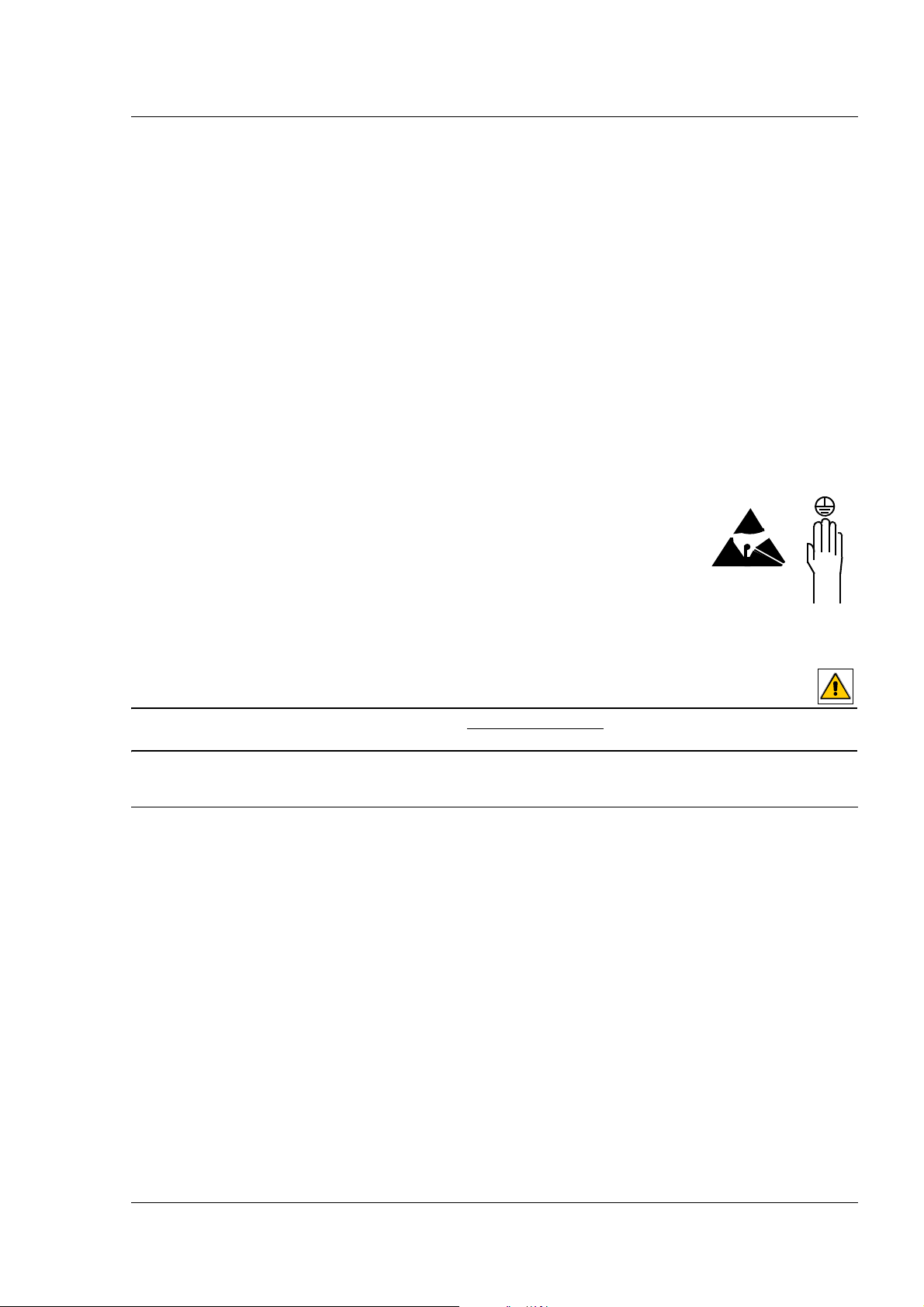
Visual Check
• Look for mechanical damage, possibly affecting radiation safety.
• Inspect cone for possible cracks.
• Check the mechanical functions.
Test the tubehead in all working positions for possible drift.
• Verify that all labels are affixed and legible.
Defaced labels must be replaced.
To order the above, write to Sirona Dental Systems (address, see rear)
giving details on: Customer Name
Customer Address
All Model Numbers with
Serial Numbers still legible on the unit for identification purposes.
For serial numbers see also Unit Passport.
4 41 62 983 D 3202.101.01.06.02
Page 5
Sirona Dental Systems GmbH Maintenance Instructions
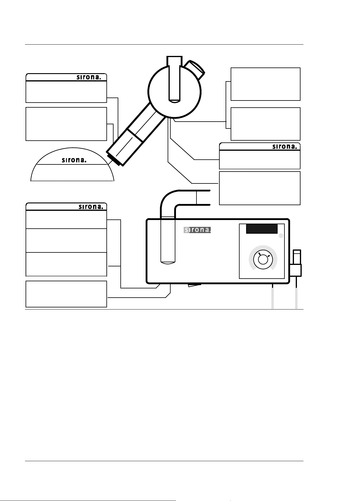
Radiation
indication
X-ray
Standby indicator lamp
(Ready LED)
D
X-ray
LED
ON
Remote control
0I
OFF
I.00
X-ray
ATTENTION RADIATION
Observe
Radiation Protection Guidelines.
See Operating Instructions.
S
D
b e e p
Exposure button
Light Indicators at the Display, Audible Sound at the Wall Adapter.
• Switch unit ON with master power switch. The stored exposure data must light up on the display,
see Operating Instructions under ”Preparing the exposure”.
• Make an exposure:
– Set the exposure time to 1.00 s for conventional radiography technique (Digital
– CAUTION RADIATION: Depress the exposure button and hold until the exposure terminates auto-
matically. The radiation indication X-ray must light up during the exposure period.
Simultaneously an audible beep must sound at the wall adapter. In operation with remote control,
the LED on the remote station must light up as well.
The Standby indicator lamp / Ready LED flashes until the automatic cooling down time of the tube
assembly has expired.
• Interrupt an exposure
– Set the exposure time to 3.2s.
– CAUTION RADIATION: Press the exposure button until X-ray lights up and subsequently release –
the exposure must terminate immediately. The selected exposure time blinks until the automatic
cooling down time of the tube assembly has expired.
• Defective light indicators constitute a safety hazard to the patient as well as to the operator.
CAUTION: The user is not permitted to use the unit until light indicators have been replaced!
41 62 983 D 3202.101.01.06.02 5
– deadman feature:
must not light up).
Page 6

Maintenance Instructions Sirona Dental Systems GmbH
Tube Current Verification
• Turn unit OFF and remove housing (see Service Manual!).
• Remove jumper from test points DX1.X6/X7.
• Connect multimeter to X6+/ X7 –, range 10mADC.
• Turn unit ON.
• Set the exposure time on the control panel to 3.2s, using the object selector switch
(conventional radiography technique).
• CAUTION RADIATION: Make an exposure.
• The reading should be 7mADC
• If specified value is obtained turn unit OFF (WARNING: Electrical shock hazard!).
• Remove meter leads and replace jumper!
– If specified value cannot be obtained, see Service Manual, chapter ”Tube Current Verification”.
6 41 62 983 D 3202.101.01.06.02
±0.5mA. z z Record reading.
Page 7

Sirona Dental Systems GmbH Maintenance Instructions
Exposure Time Verification
(conventional radiography technique)
• For testing the exposure times a mechanical pulse counter is needed.
• Switch unit OFF (WARNING: Electrical shock hazard!) and connect the test leads to testpoints MP311/
MP312 on PCB DX1.
• Switch unit ON.
• Make an exposure with each of the exposure times given. CAUTION RADIATION!
– Observe the cooling time between exposures. The Standby indicator lamp / Ready LED flashes until
the automatic cooling down time of the tube assembly has expired.
– Set exposure times using the object selector switch (see Operating Instructions).
Exposure time 0.4s at 60Hz: 24 pulses Tolerance±1 pulse, at 50Hz: 20 pulses ±1
Exposure time 3.2s at 60Hz: 192 pulses Tolerance±9 pulses, at 50Hz: 160 pulses ±8
• Record indicated pulse count. Reset counter after each exposure.
• Switch unit OFF (WARNING: Electrical shock hazard!) and disconnect pulse counter.
• If the measured pulse count is not within specified tolerance,
see Service Manual, chapter ”Exposure Time Verification”.
41 62 983 D 3202.101.01.06.02 7
Page 8

Maintenance Instructions Sirona Dental Systems GmbH
Verification of the Exposure Button
• If door contacts are installed, close door (close contacts), do not bridge contacts.
• Turn unit OFF (WARNING: Electrical shock hazard!)
• Connect multimeter to DX1 X5.3 and 4, range for measuring resistance.
• Measure resistance:
Exposure button not depressed: R > 100 kOhm
Exposure button depressed: R < 100 Ohm
The values must remain constant, even if the coiled cable is moved during the measurement.
– If the values are not present, check correct function of the door contacts.
• If the values are still not present, exchange exposure button.
• Disconnect multimeter.
• Reattach housing (see Service Manual, chapter ”Removing Housing”)
8 41 62 983 D 3202.101.01.06.02
Page 9

Sirona Dental Systems GmbH Maintenance Instructions
ON OFF
Verification of the Object Selector Switch
I.00 s
2
D
1
• Turn object selector switch (1) to the lefthand stop (turn counter clockwise).
Turn object selector switch (1) clockwise step by step (12 steps) up to the righthand stop, recordin
displayed (2) time value for each step.
• Repeat procedure and compare indicated values with recorded values.
• If the values differ between first and second reading: exchange generator DS.
41 62 983 D 3202.101.01.06.02 9
g the
Page 10

Maintenance Instructions Sirona Dental Systems GmbH
Mechanical Adjustments (if required)
Readjustment is necessary, if the tubehead does not remain stationary after being positioned.
1. Adjust spring on left support arm:
Slip bellows on both sides over the half shells A. Pull the half shells off.
Pull the scissors arm apart and push bellows over the bearing. Set both support arms vertical.
Insert torx screwdriver from above into the bore of the bearing and adjust the spring (turn clockwise
tighter).
Complete again in reverse order
2. Adjust spring on right support arm:
Slip bellows over the upper half shell A. Press the bellows down.
Bring support arm into horizontal position.
Insert torx screwdriver from the front into the bore of the bearing and adjust the spring (turn clockwise
tighter).
Complete again in reverse order.
10 41 62 983 D 3202.101.01.06.02
.
→
→
Page 11

ebiflabkq=ap
vЙ~кду=j~бенЙе~еЕЙ=`ЬЙЕвдблн
Customer: ____________________ Address: ________________________________
Dealer: _______________________ Address: ________________________________
Date of original installation: _______ Date of inspection: ________________________
Report of Assembly FD 2579 # ____
SCHEDULE Yes No Remarks
All manuals are present
Test instruments as required
Manufacturer Model Accuracy Last calibrated
Voltmeter
mAmeter
Pulse Counter
Any mechanical damage noticed
All labels are present and legible
All indicator lights are O.K.
Radiation indicator X-ray lights up, audible buzzer O.K.
Deadman feature O.K.
Tube current is within specified limits Measurement: . . . . . mA
Specified exposure time (pulses) O.K. Pulse Count: . . . . . . . .
Exposure button O.K. Resistance within specified limits
Object selector switch O.K.
Mechanical adjustment of the support arm is O.K.
The unit is in compliance with
MFG specified tests and safety
Technician:____________________ Dealer: _________________________________
41 62 983 D 3202.101.01.06.02
Page 12

ebiflabkq=ap
vЙ~кду=j~бенЙе~еЕЙ=`ЬЙЕвдблн
Customer: ____________________ Address: ________________________________
Dealer: _______________________ Address: ________________________________
Date of original installation: _______ Date of inspection: ________________________
Report of Assembly FD 2579 # ____
SCHEDULE Yes No Remarks
All manuals are present
Test instruments as required
Manufacturer Model Accuracy Last calibrated
Voltmeter
mAmeter
Pulse Counter
Any mechanical damage noticed
All labels are present and legible
All indicator lights are O.K.
Radiation indicator X-ray lights up, audible buzzer O.K.
Deadman feature O.K.
Tube current is within specified limits Measurement: . . . . . mA
Specified exposure time (pulses) O.K. Pulse Count: . . . . . . . .
Exposure button O.K. Resistance within specified limits
Object selector switch O.K.
Mechanical adjustment of the support arm is O.K.
The unit is in compliance with
MFG specified tests and safety
Technician:____________________ Dealer: _________________________________
41 62 983 D 3202.101.01.06.02
Page 13

ebiflabkq=ap
vЙ~кду=j~бенЙе~еЕЙ=`ЬЙЕвдблн
Customer: ____________________ Address: ________________________________
Dealer: _______________________ Address: ________________________________
Date of original installation: _______ Date of inspection: ________________________
Report of Assembly FD 2579 # ____
SCHEDULE Yes No Remarks
All manuals are present
Test instruments as required
Manufacturer Model Accuracy Last calibrated
Voltmeter
mAmeter
Pulse Counter
Any mechanical damage noticed
All labels are present and legible
All indicator lights are O.K.
Radiation indicator X-ray lights up, audible buzzer O.K.
Deadman feature O.K.
Tube current is within specified limits Measurement: . . . . . mA
Specified exposure time (pulses) O.K. Pulse Count: . . . . . . . .
Exposure button O.K. Resistance within specified limits
Object selector switch O.K.
Mechanical adjustment of the support arm is O.K.
The unit is in compliance with
MFG specified tests and safety
Technician:____________________ Dealer: _________________________________
41 62 983 D 3202.101.01.06.02
Page 14

ebiflabkq=ap
vЙ~кду=j~бенЙе~еЕЙ=`ЬЙЕвдблн
Customer: ____________________ Address: ________________________________
Dealer: _______________________ Address: ________________________________
Date of original installation: _______ Date of inspection: ________________________
Report of Assembly FD 2579 # ____
SCHEDULE Yes No Remarks
All manuals are present
Test instruments as required
Manufacturer Model Accuracy Last calibrated
Voltmeter
mAmeter
Pulse Counter
Any mechanical damage noticed
All labels are present and legible
All indicator lights are O.K.
Radiation indicator X-ray lights up, audible buzzer O.K.
Deadman feature O.K.
Tube current is within specified limits Measurement: . . . . . mA
Specified exposure time (pulses) O.K. Pulse Count: . . . . . . . .
Exposure button O.K. Resistance within specified limits
Object selector switch O.K.
Mechanical adjustment of the support arm is O.K.
The unit is in compliance with
MFG specified tests and safety
Technician:____________________ Dealer: _________________________________
41 62 983 D 3202.101.01.06.02
Page 15

ebiflabkq=ap
vЙ~кду=j~бенЙе~еЕЙ=`ЬЙЕвдблн
Customer: ____________________ Address: ________________________________
Dealer: _______________________ Address: ________________________________
Date of original installation: _______ Date of inspection: ________________________
Report of Assembly FD 2579 # ____
SCHEDULE Yes No Remarks
All manuals are present
Test instruments as required
Manufacturer Model Accuracy Last calibrated
Voltmeter
mAmeter
Pulse Counter
Any mechanical damage noticed
All labels are present and legible
All indicator lights are O.K.
Radiation indicator X-ray lights up, audible buzzer O.K.
Deadman feature O.K.
Tube current is within specified limits Measurement: . . . . . mA
Specified exposure time (pulses) O.K. Pulse Count: . . . . . . . .
Exposure button O.K. Resistance within specified limits
Object selector switch O.K.
Mechanical adjustment of the support arm is O.K.
The unit is in compliance with
MFG specified tests and safety
Technician:____________________ Dealer: _________________________________
41 62 983 D 3202.101.01.06.02
Page 16

tЙ=кЙлЙкоЙ=нЬЙ=кбЦЬн=нз=г~вЙ=~еу=~днЙк~нбзел=пЬбЕЬ=г~у=ДЙ=кЙимбкЙЗ=ЗмЙ=нз=нЙЕЬебЕ~д=бгйкзоЙгЙенлK
«=pбкзе~=aЙен~д=pулнЙгл=dгДe=NVVU pйк~ЕЬЙW=ЙеЦдблЕЬ= mкбенЙЗ=бе=dЙкг~еу
a=POMOKNMNKMNKMSKMO===MOKOMMS ûKJkêKW= NMT=NUP fгйкбг¨=Йе=^ддЙг~ЦеЙ
pбкзе~=aЙен~д=pулнЙгл=dгДe
áå=íÜÉ=rp^W áå=`~å~Ç~W
c~Дкбвлнк~≈Й=PN
SQSOR=_ЙелЬЙбг
dЙкг~еу
пппKлбкзе~KЕзг
pбкзе~=aЙен~д=pулнЙгл=ii`
QUPR=pбкзе~=aкбоЙI=pмбнЙ=NMM
`Ь~кдзннЙI=k`=OUOTP
rp^
pбкзе~=`~е~З~
PORM=oбЗЦЙп~у=aкбоЙ=J=rебн=R
jбллблл~мЦ~I=lен~кбз=iRi=RvS
`~е~З~
lêÇÉê=kç
QN=SO=VUP=a=POMO
 Loading...