

Page 1

$
7IVZMGI1ERYEP
IMPORTANT:
• Please note that we have revised this version of the Service
Manual.
It is therefore necessary that you no longer use the first edition.
• In case of faults which you are unable to eliminate with the help
of this manual, please contact our Customer Service.
• It is essential that you take this Service Manual with you for
every visit to a customer.
Furthermore, you must always have the spare parts list and
the wiring diagrams with you as well.
You can order additional copies of this Service Manual under the
• order number
department
See reverse side of manual for address.
58 35 694
in Bensheim.
GZP
from our
:IVWMSR
D 3344.076.01.04.02 03.2002
Page 2

Page 3
$
7IVZMGI1ERYEP
Page 4

Additional requirements:
• Spare parts list
Order No. 58 62 581
• Circuit diagrams
Acquisition unit: Order No. 58 35 710
Milling unit: Order No. 58 35 728
CEREC 3 / CEREC Scan
• Tools
– Hexagonal screwdriver (90° offset): Sizes 1.5; 2; 2.5; 4; 6
– Fork wrench, sizes 5.5; 8; 10; 14
– Torque screw driver, sizes 5, 6, 20, 25, 40
– Philips-head screw driver Size 1
– Slot screw driver, insulated, Size 2, 3
– Socket wrench 8mm
– Cutting pliers
– Special tool for monitor nut
– Special tool for locking button: Order No.: 59 08 947
• Accessories
– Digital multimeter, accuracy class: 1
– Soldering tool for repairing cables
– Side cutting pliers
– Cable ties
– Teflon tape
– PS2 mouse (recommended)
– PS2 keyboard (recommended)
– 3.5” disk
– Calibration piece and pins (recommended)
– Fuses (recommended):
F1/F2 (2 pcs.) 5AT, Order No.: 20 33 111
F1/F2 (2 pcs) for acquisition unit starting with Ser. No.: 3300
6,3 AT, Order No.: 10 77 452
F3 1.25AL Order No.: 59 15 181
F4 2AT Order No.: 10 80 522
Page 5
General 1
Service Software
Trouble Shooting: Milling Unit
Trouble shooting: Acquisition Unit
Settings
2
3
4
5
Acquisition Unit: Repairs
Milling Unit: Repairs
Installing Software
6
7
8
Page 6

Page 7

List of Contents
General ................................................................................................................................... 1-1
1
1.1 General Notes .............................................................................................................. 1-3
Service Software .................................................................................................................... 2-1
2
2.1 General Notes .............................................................................................................. 2-3
2.2 Basic Structure of Test Dialogs .................................................................................... 2-5
2.3 Individual Test Points ................................................................................................. 2-10
Trouble Shooting: Milling Unit................................................................................................. 3-1
3
3.1 Device cannot be switched ON. Green LED (Ready for operation) not illuminated... 3-5
3.2 No connection to PC / acquisition unit. Software cannot be installed .......................... 3-7
3.3 No air pressure ............................................................................................................. 3-9
3.4 Fan not running. Unit shuts down completely after a short time ................................ 3-11
3.5 Water pump: Pressure too low ................................................................................... 3-13
3.6 Defective light barrier ................................................................................................. 3-15
3.7 Door switch. Please close milling chamber door........................................................ 3-17
3.8 Motor locking positions: Problems changing grinders ................................................ 3-19
3.9 Stepping motors (milling unit). Loss of steps.............................................................. 3-21
3.10 Touch errors ............................................................................................................... 3-23
3.11 Trouble shooting. Defective CCP board..................................................................... 3-25
Trouble shooting: Acquisition Unit.......................................................................................... 4-1
4
4.1 System cannot be switched ON ................................................................................... 4-7
4.2 PC not booting properly I.............................................................................................. 4-9
4.3 PC not booting properly II........................................................................................... 4-11
4.4 PC does not respond during switch-on, PC power supply does not start .................. 4-12
4.5 Further PC faults ........................................................................................................ 4-14
4.6 Monitor image flickering ............................................................................................. 4-15
4.7 No monitor display...................................................................................................... 4-17
4.8 Incorrect monitor display format size.......................................................................... 4-19
4.9 Monitor: Color shade/gray scale is too weak.............................................................. 4-21
4.10 Trackball not functioning ............................................................................................ 4-23
4.11 Trackball buttons not functioning................................................................................ 4-25
4.12 Pedal not functioning .................................................................................................. 4-27
4.13 Keyboard not functioning /defective ........................................................................... 4-29
4.14 No camera image ....................................................................................................... 4-31
4.15 Incorrect measuring sensor setting ............................................................................ 4-33
4.16 Camera calibration: messages................................................................................... 4-35
4.17 Interference at radio interface .................................................................................... 4-37
4.18 No sound or sound level too low ................................................................................ 4-41
4.19 No Sirocam camera image......................................................................................... 4-43
4.20 Sirocam camera image interference .......................................................................... 4-45
58 35 694 D 3344
D 3344.076.01.04.02 03.2002
V
Page 8

List of Contents
4.21 SIROCAM camera: Incorrect image settings .............................................................. 4-47
4.22 Digital X-ray problems ................................................................................................. 4-49
Settings....................................................................................................................................5-1
5
5.1 Monitor Settings ............................................................................................................ 5-3
5.2 Calibrating the 3D camera ............................................................................................ 5-4
5.3 Pairing the DECT-radio interface (EU) .......................................................................... 5-5
5.4 Replacing a module of the DECT radio interface (EU) ................................................. 5-8
5.5 Pairing the Futaba radio interface (USA/Japan) ........................................................... 5-9
Acquisition Unit: Repairs .........................................................................................................6-1
6
6.1 Electrical and Electromechanical Components............................................................. 6-4
6.2 Mechanical components ............................................................................................. 6-30
Milling Unit: Repairs.................................................................................................................7-1
7
7.1 Milling Unit: General Activities....................................................................................... 7-3
7.2 Replacing the Scanner.................................................................................................. 7-5
7.3 Replacing the Drive and/or Motor ............................................................................... 7-11
7.4 Checking / Adjusting Stop positions ............................................................................ 7-13
7.5 Stepping Motors: Replacing / Adjustment ................................................................... 7-15
Installing Software ...................................................................................................................8-1
8
8.1 Acquisition Unit: Network Installation ............................................................................ 8-3
8.2 How to install an MO drive .......................................................................................... 8-25
VI
58 35 694 D 3344
D 3344.076.01.04.02 03.2002
Page 9

CEREC 3
1
General
Page 10

List of Contents
General
List of Contents
1.1 General Notes ..................................................................................................................... 1-3
1 - 2
58 35 694 D 3344
D 3344.076.01.04.02 03.2002
Page 11
1.1 General Notes
1.1 General Notes
Nominal line voltage ranges
Faults in electronic medical
equipment caused by mobile
phones
Opening the device
Measurements
The CEREC® 3 acquisition unit can be used in the following
voltage ranges
• Europe 230VAC / 50Hz
• USA 115VAC / 60Hz
• Japan 100VAC / 50Hz and 60Hz
The CEREC 3 / CEREC Scan milling unit can be used in the following
nominal line voltage ranges
• 100V
When opening the device:
Always switch OFF the device before connecting the measuring instrument.
Select the correct current/voltage type and adjust the measuring range to
match the expected readings.
:
:
230VAC; 50/60Hz
–
In order to ensure safe operation of electronic medical equipment,
the use of mobile phones in practices and hospital areas is strictly
prohibited.
Please observe the necessary precautions when handling
printed circuit boards (ESD).
Touch a ground point to discharge static electricity before
handling any components.
nominal line
1.1
When replacing parts
Repairing and/or upgrading the
PC drawer
Disposal
Perform continuity tests only on devices which are switched off.
Switch OFF the device before replacing any parts.
For safety reasons
supply when replacing parts around the line transformer.
The item numbers for ordering spare parts can be found in the
spare parts list, Order No. 58 62 581.
The diagrams contained in the spare parts list provide a useful guide when
replacing parts.
Replace the broken warranty seal on the bottom side of the PC drawer with
the supplied seal of conformity.
Please observe the instructions found in the relevant user guide.
the device should be disconnected from the power
58 35 694 D 3344
D 3344.076.01.04.02 03.2002
1 - 3
Page 12

Page 13

CEREC 3
2
Service Software
Page 14

List of Contents
Service Software
List of Contents
2.1 General Notes ..................................................................................................................... 2-3
2.2 Basic Structure of Test Dialogs ........................................................................................... 2-5
2.3 Individual Test Points .......................................................................................................... 2-10
2 - 2
58 35 694 D 3344
D 3344.076.01.04.02 03.2002
Page 15
2.1 General Notes
NOTE
i
2.1 General Notes
Test requirements
Service Software Log File
Requirement for all tests:
• PC / acquisition unit are switched on and ready for operation.
• PC / acquisition unit and milling unit are interconnected (per interface ca-
ble or radio link)
• The software has been loaded for the milling unit (see Operating Instructions for Milling Unit/Milling Unit Scan, Switching the units on,
start-up
• The door of the milling chamber must remain closed as long as any motors or the water pump are running.
If the door of the milling chamber is opened during the test, all motors and
the water pump will switch off immediately (same function as pressing the
Stop button).
• The tools (burs) must be installed already during operation of the water
pump.
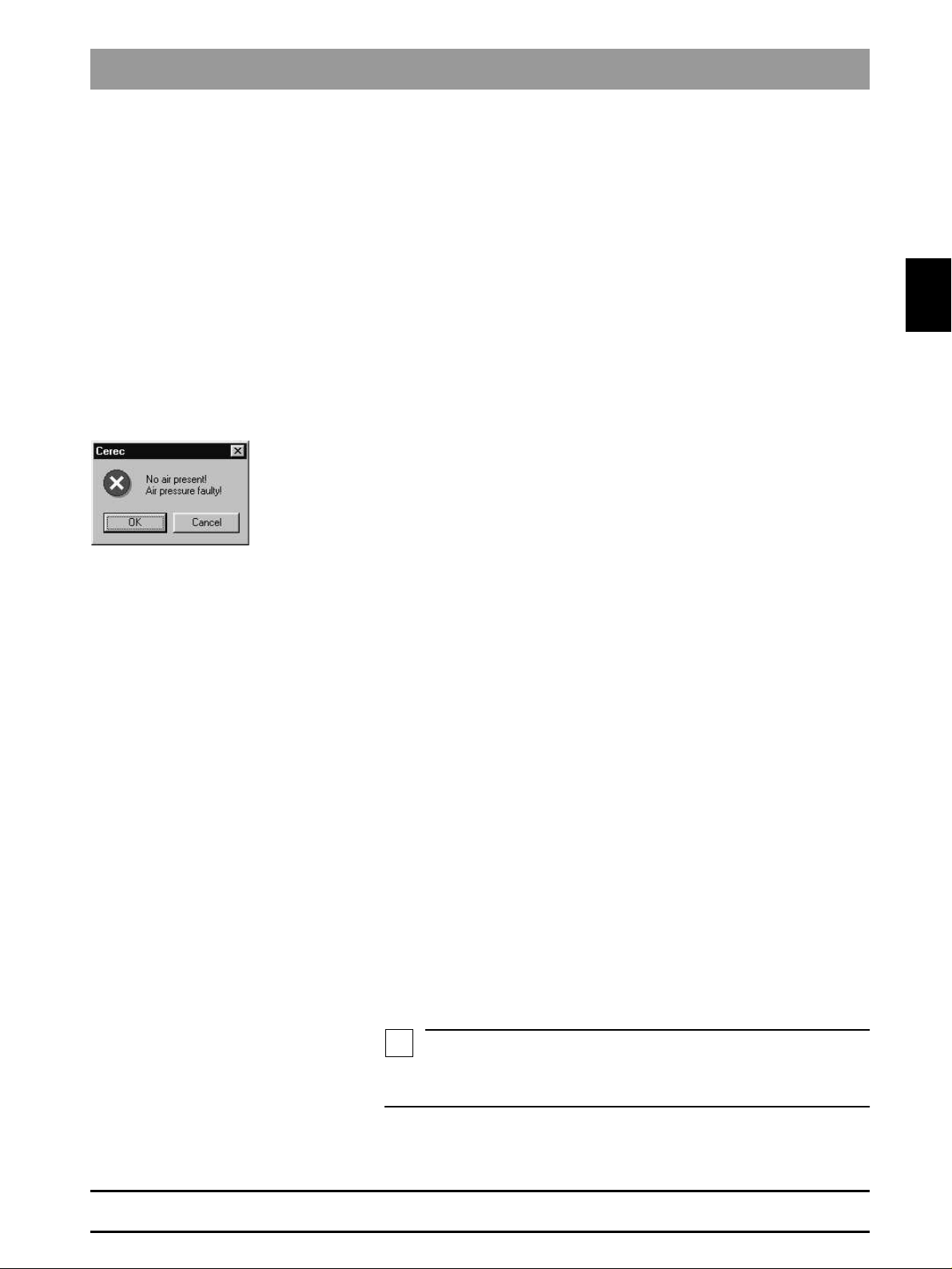
• During operation of the water pump, the air pump must always be running
to protect the gearing against water damage, i.e. the air pump is started
first. If the air pressure switch detects no air pressure, an error message
will appear and the test can not be performed.
The service software is a component of the product software. This software
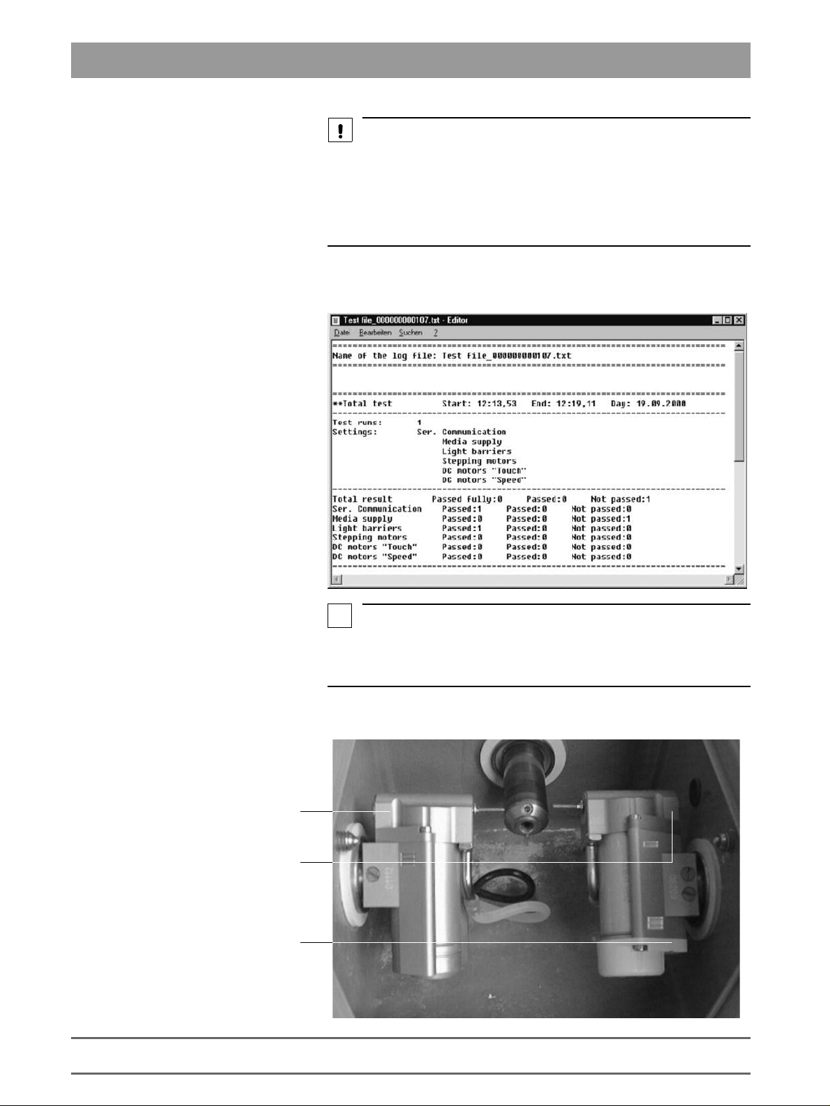
generates a log file for all tests performed.
This log file is located on delivery in the directory
c:\programme\Cerec\System\Service\Protocols
Test file_XXXXXXXXXXXX.TXT
The Xs here denote the serial no. of the controller board.
Each time the service software is started, a confirmation query appears asking whether this file (if it already exists) should be deleted. If NO (do not
delete) is selected, the tests subsequently performed will be appended to the
ones previously saved. Each test is labeled with a starting and ending date.
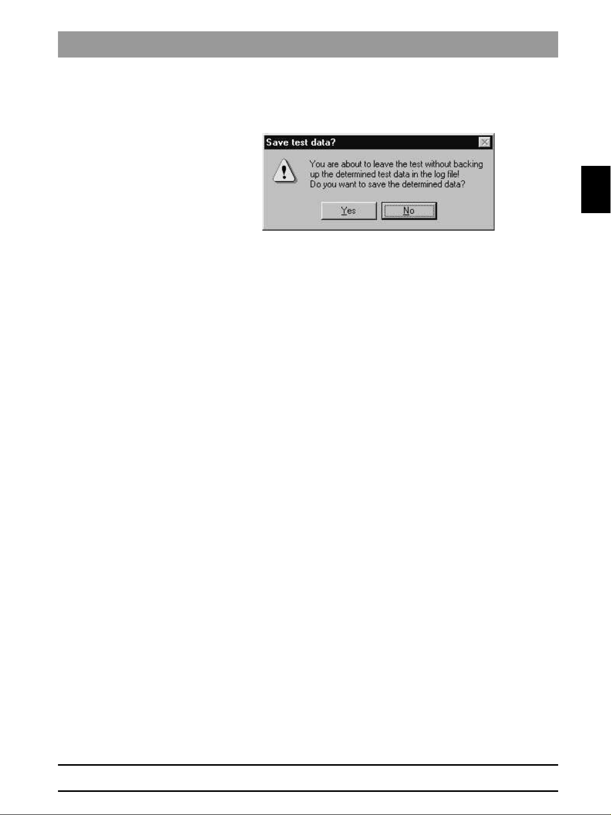
The test file can be viewed with the editor at any time. If the user exits from a
test without saving it, he will be asked if he really wants to quit without saving.
If Yes (Quit without saving) is then selected, the data just measured will be
lost.
).
and is named
Initial
2.1
Assessment scores
58 35 694 D 3344
D 3344.076.01.04.02 03.2002
After completing a test section, the log file must be saved under a new name
to a diskette belonging to the corresponding unit.
There are three different scores which can be assigned to test results:
• Passed fully (green label)
• Passed (yellow label)
• Not passed (red label)
These assessment categories apply starting with
R600
The score
case
n.a.
Passed
(not applicable) will be written to the log file for this score.
(yellow label) may be irrelevant for a specific test. In this
software version V1.1
2 - 3
Page 16
2.1 General Notes
CAUTION
To ensure trouble-free operation of the system, all test results should be labeled
"Passed fully"
If the test results are marked
this point of time.
If the test results are labeled
fault(s)
.
"Passed"
"Not passed"
, uncritical changes have occurred at
, you must find and correct the
Example of test protocol:
Path:
c:\programme\Cerec\System\Service\Protocols
i
NOTE
If the milling unit housing is left open, the temperature switch on the CC PC
board may cut out after a short time (T>90°C). The cooling fan can work properly only with the cover closed.
Overview of gearing unit:
Gearing 3
Gearing 1
Gearing 2
(without function)
2 - 4
58 35 694 D 3344
D 3344.076.01.04.02 03.2002
Page 17
2.2 Basic Structure of Test Dialogs
NOTE
i
CAUTION
NOTE
i
CAUTION
NOTE
i
2.2 Basic Structure of Test Dialogs
For a functional description of the menu items, see the user’s manual.
Password protection
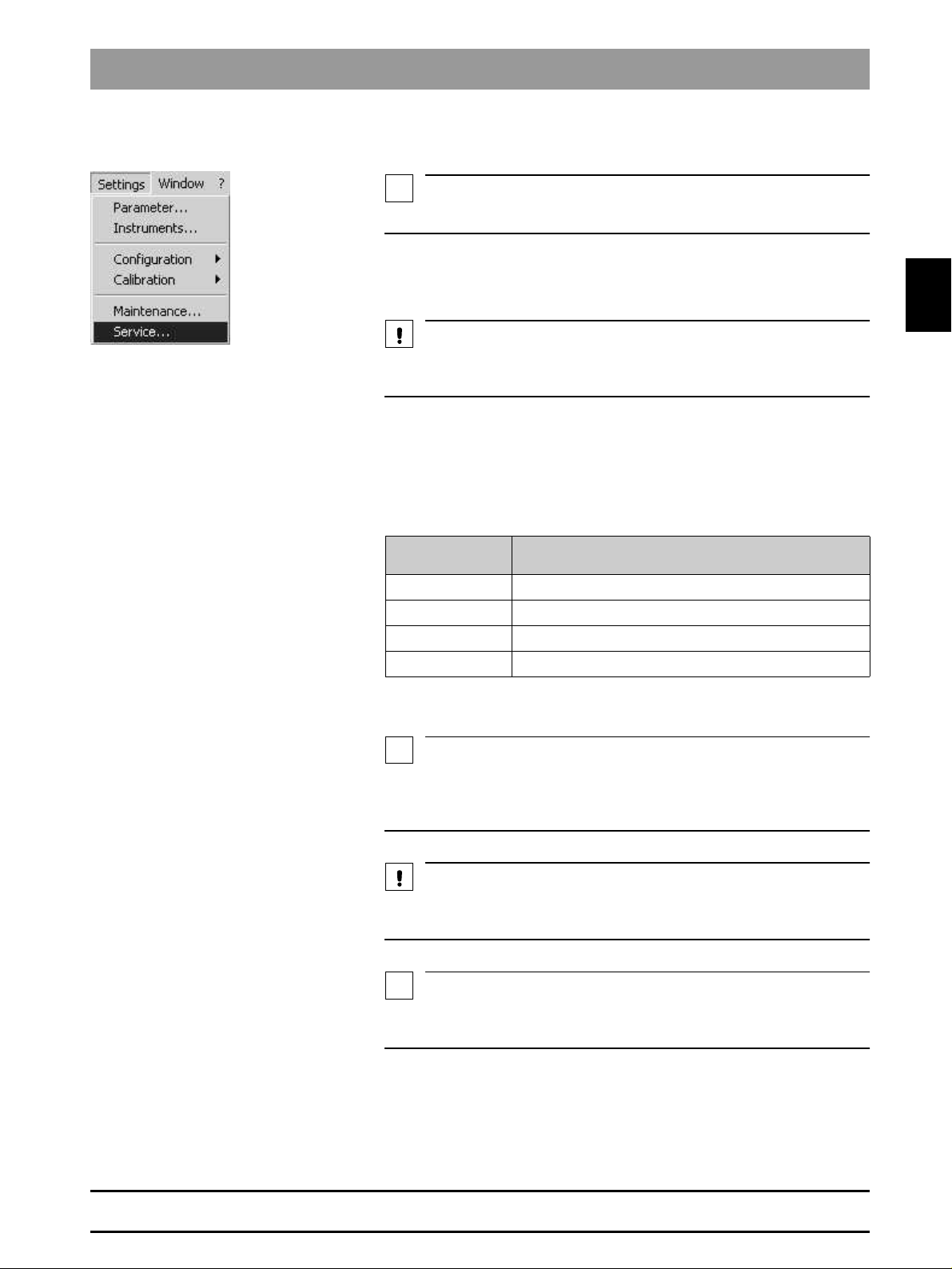
Via the
• select a wide range of Service functions with
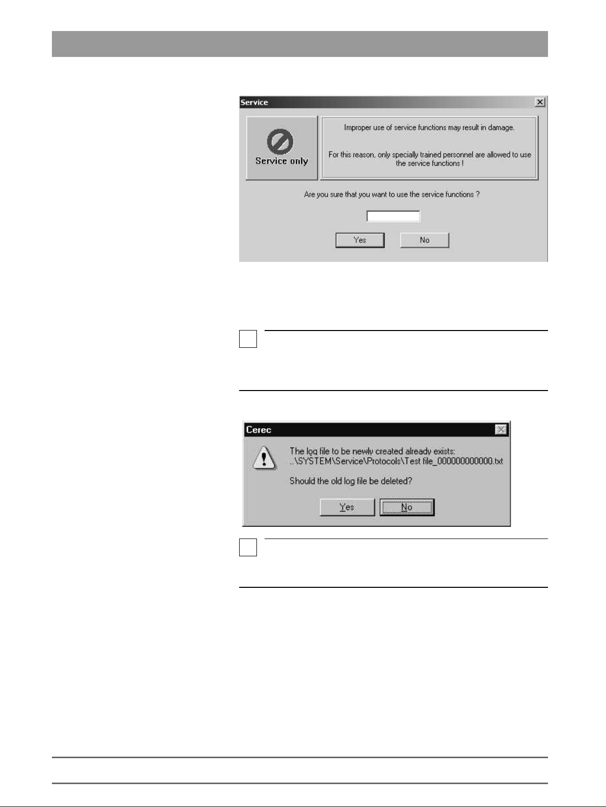
The Service functions may be used only by authorized service technicians
who have been trained by Sirona.
The service software test dialogs are protected by a password to prevent
manipulations by unauthorized users.
The password has four digits. It changes daily and is generated from the system date of the computer according to the following scheme:
Example: 24.05.2001 becomes 5042
Service
Password
number
1 2. number of the current month
2 1. number of the current month
3 2. number of the current day
4 1. number of the current day
menu you can ...
Settings/Service...
Generated from
2.2
58 35 694 D 3344
D 3344.076.01.04.02 03.2002
Since the password is thus valid for only one day, it may be passed on to the
user in exceptional cases, e.g. when providing him with emergency help over
the phone.
The password should always be treated confidentially. Before entering the
password, always determine the date as inconspicuously as possible.
If you enter the correct password, and the commands are nevertheless not enabled, first check the system date of the computer.
The dialog for setting the system time can be called up in all Windows operating systems by double-clicking the time displayed in the status line.
2 - 5
Page 18
2.2 Basic Structure of Test Dialogs
Now enter the password.
Log file
If you confirm this
open.
i
NOTE
If a log file named after the milling unit already exists at the time of the program
start, a confirmation query will appear asking if the data from the new test run
should be appended to the existing file or it should be deleted first.
i
NOTE
If the display "…0000.txt" appears, this means that there is no connection to
the milling unit.
Service
dialog with
Yes
, the
Test selection
dialog box will
2 - 6
Possible causes:
• The CEREC 3 program has been started more than once
• There is no (cable or radio-link) connection between the milling unit and
the acquisition unit/PC
• The software download to the milling unit has not been completed.
58 35 694 D 3344
D 3344.076.01.04.02 03.2002
Page 19
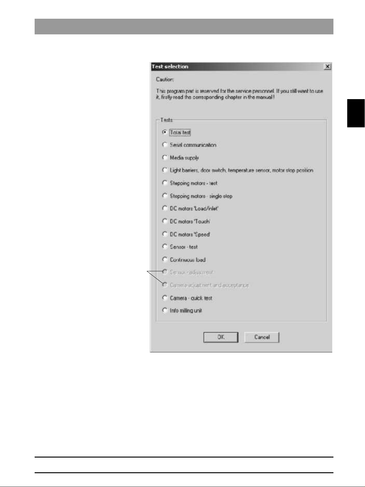
Test selection dialog
Tests performed only at
the factory
2.2 Basic Structure of Test Dialogs
2.2
58 35 694 D 3344
D 3344.076.01.04.02 03.2002
In the
Test selection
• a
Total test
• an individual test.
The selected test dialog is then opened by clicking on
dialog you can select …
(default selection on delivery) or
OK
.
2 - 7
Page 20
2.2 Basic Structure of Test Dialogs
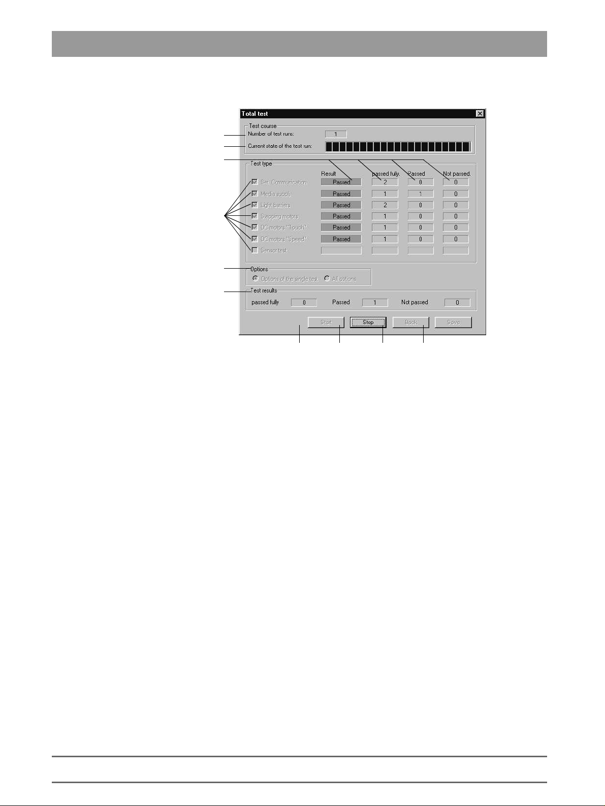
Example: Total test
1
2
10
3
4
5
6 789
Number of test runs completed since the last time the
1.
tuated.
Status bar for current state of test run.
2.
Check boxes for selecting (activating/deactivating) the tests available in
3.
this test dialog.
Check box for selecting the options possible in this test dialog.
4.
Number of test results since the last
5.
– Passed fully
– Passe d
– Not passed
Pressing
6.
The test run will be repeated until it is interrupted with the Stop button.
The test run counter is then reset to 0.
Once started, the test run can be halted only with Stop. No other inputs are
possible during the test run.
The test is canceled as soon as possible with
7.
The test in progress at the time of cancellation is not counted. All inputs are
now possible again.
stores all existing data to the log file. The data are appended to the
Save
8.
previously existing log file (if the current test run has not yet been saved).
If no data exist, a message to that effect will appear (confirm with
Once a test run has been saved to the log file, a new test run must be started before selecting the save function again.
initiates the test run with the selecting settings.
Start
Start:
Stop
.
button was ac-
Start
OK
).
2 - 8
58 35 694 D 3344
D 3344.076.01.04.02 03.2002
Page 21
2.2 Basic Structure of Test Dialogs
Press
9.
If any data exist and have not yet been saved, you will be queried whether
or not the test data should be saved.
Result:
10.
• No color =>
• Green => Measurement shows that test was
• Yellow => Measurement shows that test was
• Red => Measurement shows that test was
to quit the test dialog and return to the service dialog.
Back
measurement available yet
No
fully
passed
Passed
Passed
Not
2.2
58 35 694 D 3344
D 3344.076.01.04.02 03.2002
2 - 9
Page 22
2.3 Individual Test Points
g
2.3 Individual Test Points
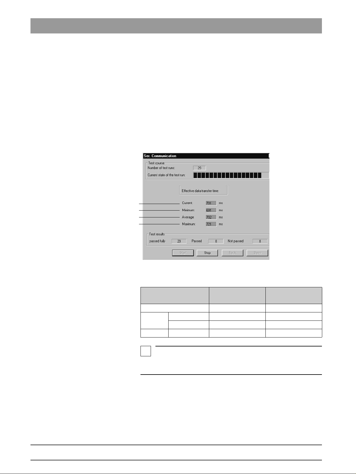
2.3.1 Serial Communication
The test is primarily used to measure the speed and quality of data transmission. This is especially important if the system is not operated through the
standard line (RS-232 max. 10 m), but via other types of connections instead
e.g. an infrared link, a DECT coupling or over longer distances via interface
converters e.g. RS-422.
The transmission time between the beginning of transmission and the end of
reception is calculated for a specific data record on the PC. A test run comprises one complete transmission in both directions.
The values thus measured are then saved to the log file.
Result of last test run
Minimum measured transmission time
e measured transmission time
Avera
Maximum measured transmission time
Typical values:
COM1
Baud rate: 115200
Cable 400-500ms –
Radio
i
The limiting values and color coding refer to a
baud rate of 115200.
Europe 600-750ms –
USA/Japan – 2-3s
NOTE
COM1
Baud rate: 19200
Purpose of Test:
2 - 10
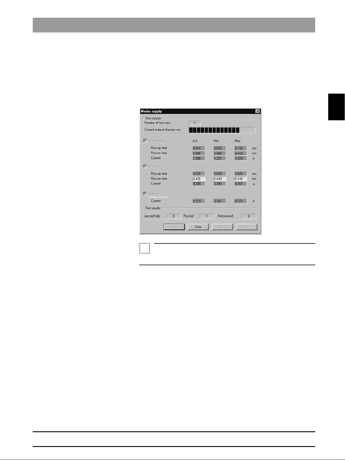
2.3.2 Media supply
To check the media supply (air, water, fan) for proper functioning and test the
pressure switches and the run-up time of the pump.
58 35 694 D 3344
D 3344.076.01.04.02 03.2002
Page 23
2.3 Individual Test Points
NOTE
i
Procedure
Save
The pumps and the fan are switched on by nominal select control depending
on selection. The motor currents and the condition of the pressure switches
are registered. The points of time when the pressure detectors respond are
measured. After approx. 5 seconds the pumps are switched off and the time
required until the pressure switch responds is measured and evaluated.
Save stores the measured values to the log file under the heading of Media
supply.
2.3
Deviations of measurements
The limiting values apply to a completely filled water circuit.
Deviations may occur:
• During the first test run (if any air is still in the water circuit)
• If the amount of water in the water tank is insufficient
• After filling the water tank.
58 35 694 D 3344
D 3344.076.01.04.02 03.2002
2 - 11
Page 24
2.3 Individual Test Points
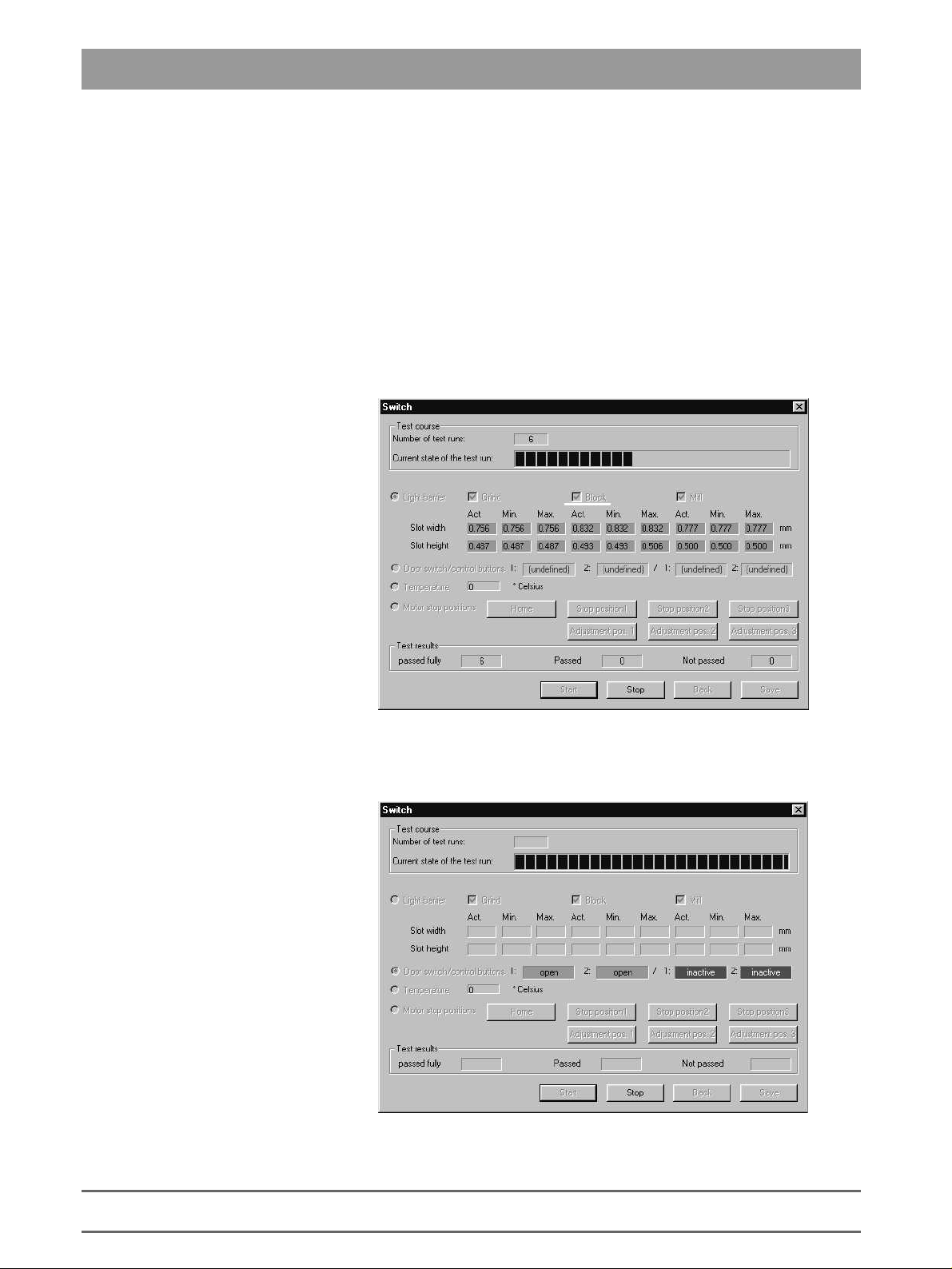
2.3.3 Light Barriers, Door Switch, Temperature Sensor and Motor Stop Positions
Purpose of Test:
Light Barriers
This test serves to evaluate the safe functioning of the light barriers and check
the door switch, the temperature sensor and the motor stop positions.
When the end position is located, the slot of the gear is measured via the
width and height at which the stepping motor positions are registered with the
flanks.
The light barriers to be tested can be selected in all variations. If no light barrier is selected, the Start button is not active.
Default setting: All light barriers selected.
Door Switch/Control Keys
2 - 12
The current state of the door switch and control keys can be checked via a
status bar display.
58 35 694 D 3344
D 3344.076.01.04.02 03.2002
Page 25
2.3 Individual Test Points
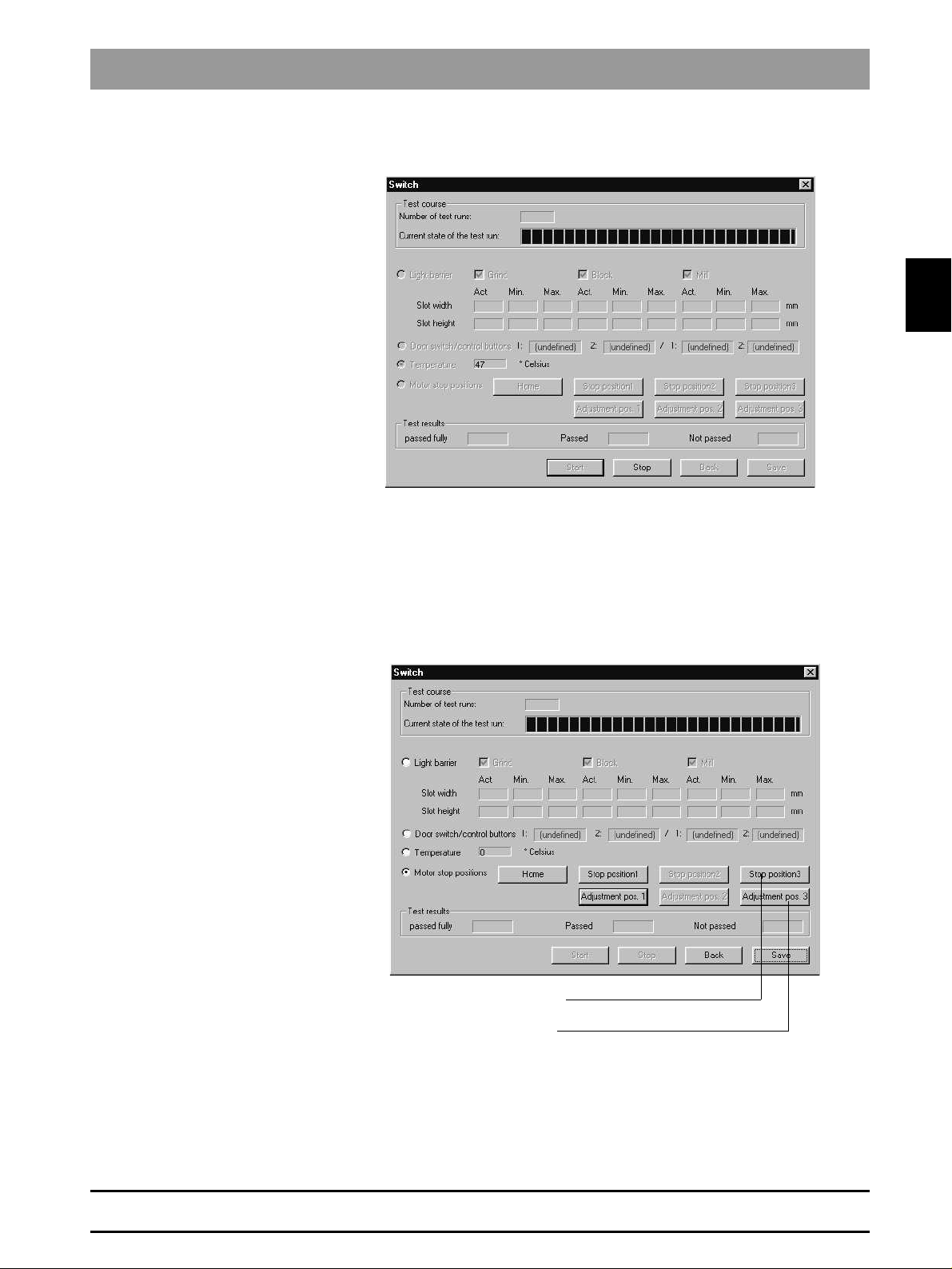
Temperature
Motor Stop Positions
A temperature display has been realized to check the temperature of the milling machine.
In the
Test selection
setting.
The motors are moved to these positions to test the motor stop positions.
Depending on which button is selected, the motors move to the corresponding position and stop there.
The motors can be reset to their home positions by pressing the
dialog,
Motor stop positions
is defined as the default
button.
Home
2.3
58 35 694 D 3344
D 3344.076.01.04.02 03.2002
Stop position for tool change
Aux. position for replacing components
If the home position can not be reached or lost steps occur during motor
movement, this will be reported.
2 - 13
Page 26
2.3 Individual Test Points
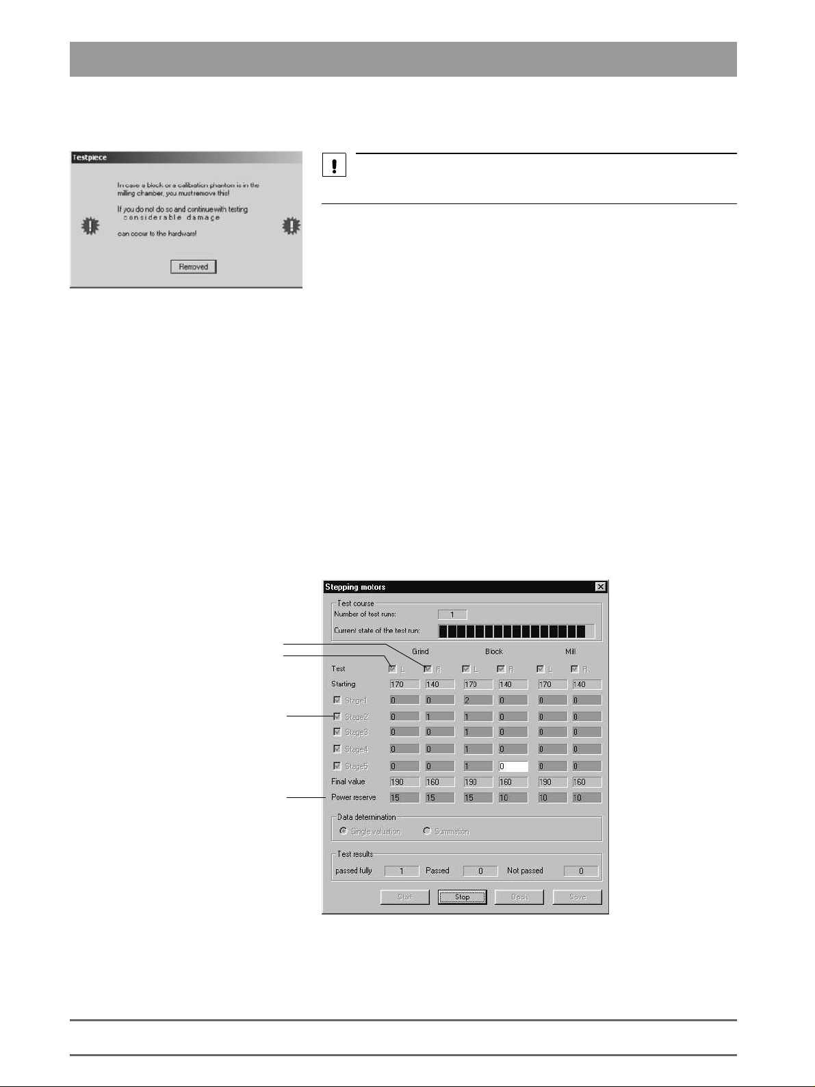
2.3.4 Stepping Motor Test
CAUTION
Observe the warnings in the
Testpiece
dialog.
Purpose of Test:
Procedure
Display of Test Results
Longit. movement
This test serves to evaluate the functioning of the stepping motors. The stepping motors are tested and evaluated for this purpose. The evaluation is made
based on a factor for the reserve capacity of each stepping motor. In addition,
this test can also be used for installation and adjustment purposes as well as
to break in the milling machine.
It is possible to individually trigger and test the stepping motors in various
combinations.
The stepping motors are run at various speed settings via an acceleration
table and the resulting step losses are measured. The number of step loss
events is then registered and evaluated. Finally, a reserve capacity is
assigned to each motor based on this data.
In order to satisfy different requirements for adjustment and testing purposes,
this test also offers the option of choosing between data summation and display of the results for individual test runs.
Rotation
2 - 14
Standard
Refers to Stage 2
58 35 694 D 3344
D 3344.076.01.04.02 03.2002
Page 27
2.3 Individual Test Points
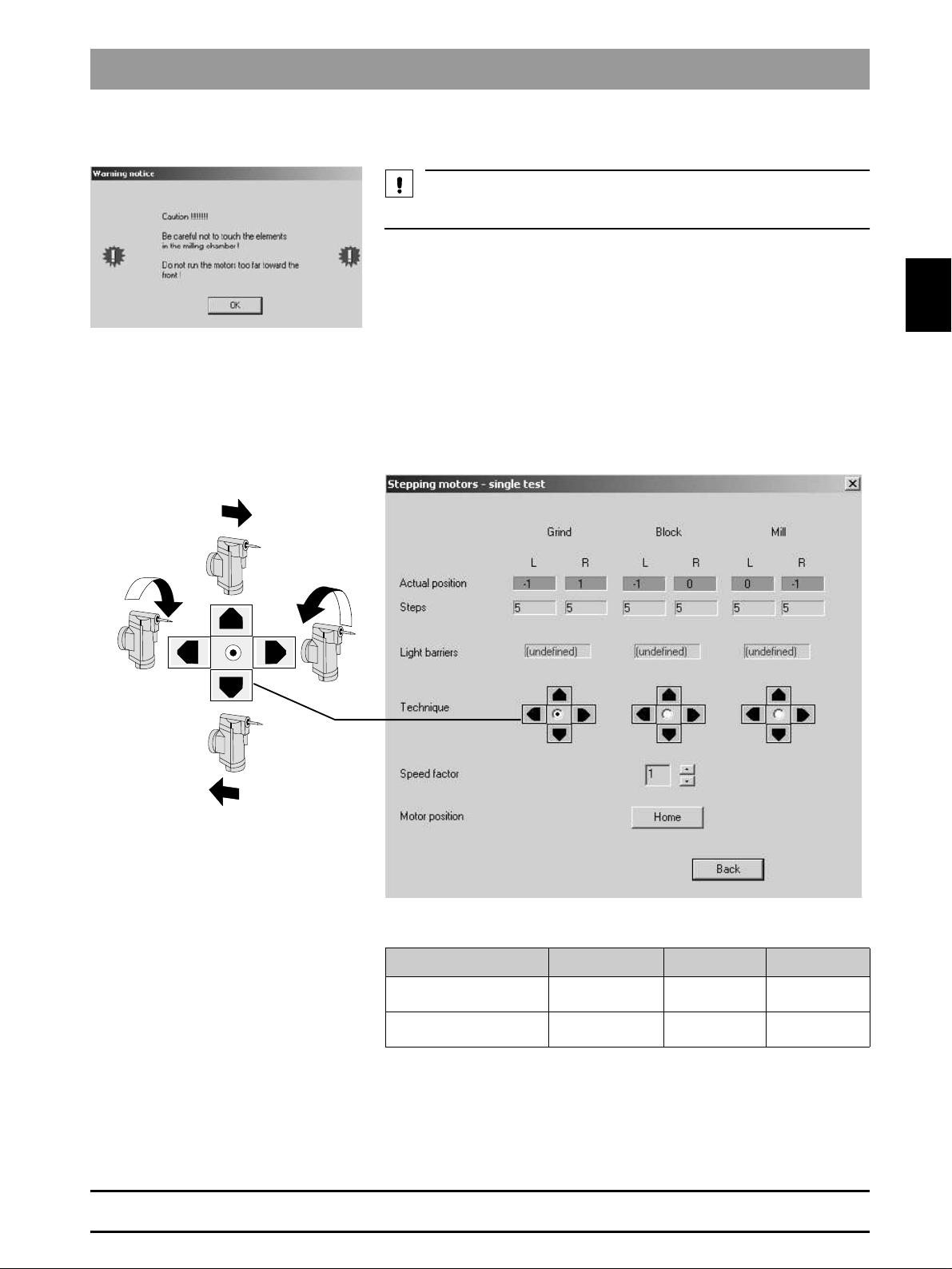
CAUTION
2.3.5 Stepping Motors - Single Step
Observe the warnings in the opened dialog.
2.3
Purpose of Test:
Procedure
The test is used to control the motors individually in case of malfunction.
Using the
nal and rotation directions.
buttons, you can move the individual motors in the longitudi-
Move
58 35 694 D 3344
D 3344.076.01.04.02 03.2002
One longitudinal step (L)
equals
One rotational step (R)
equals
Grind Block Mill
12.5µm 12.5µm 12.5µm
approx. 0.04°
(2.5’)
approx. 0.13°
(7.7’)
approx. 0.04°
(2.5’)
2 - 15
Page 28
2.3 Individual Test Points
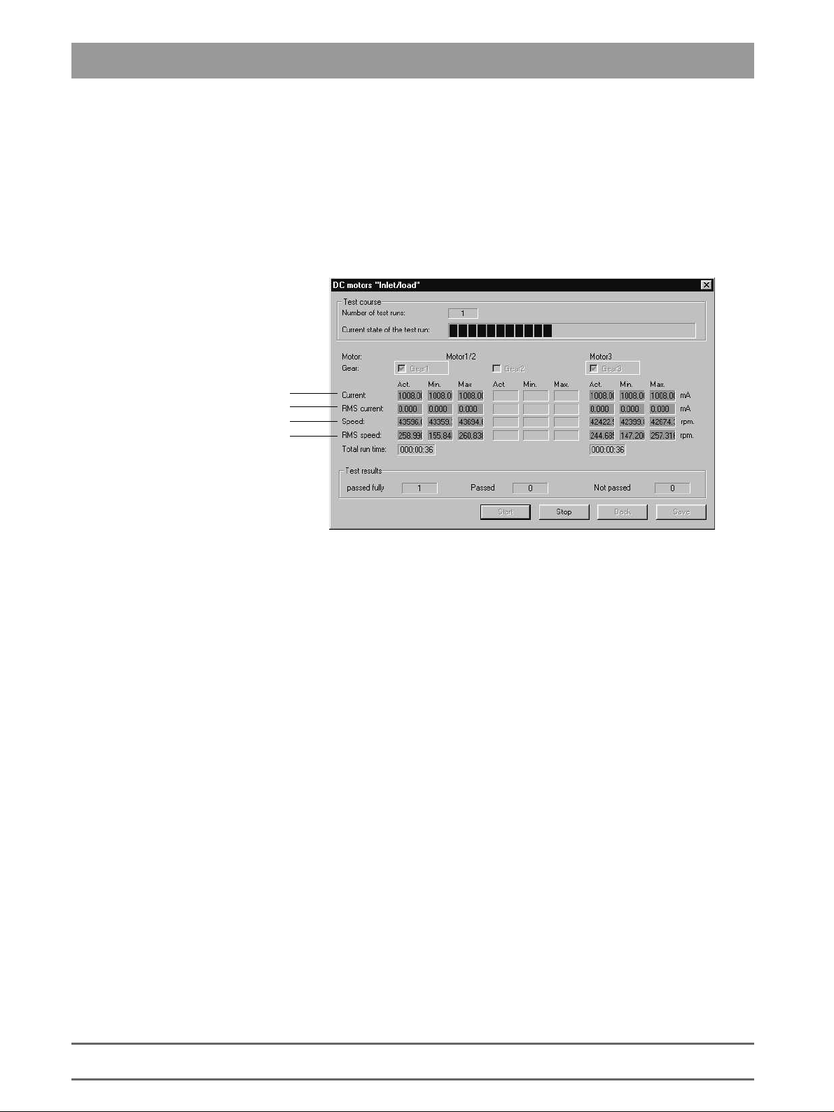
2.3.6 DC Motors "Inlet/Load"
Purpose of Test:
Procedure
Motor current
Always 0, since motor current preset
Actual speed
Measure of speed fluctuation
This test serves to run in the DC motors and check them for proper functioning
under continuous load.
The DC motors are tested through operation at a constant current. The resulting speed provides an indication of the running resistance of the gearing units.
The two motors (Motor 1 and Motor 3) can be selected together or separately.
If no motor is selected, the Start button is not active. Default: Both motors
selected.
The test runs in an endless loop until the
Test Run
The current measured values are displayed. A test run consists of one part
run time and one part pause for each motor.
:
button is actuated.
Stop
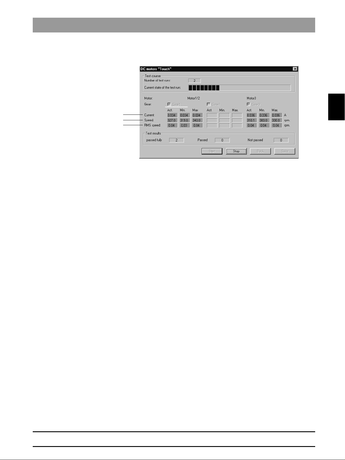
Purpose of Test:
2 - 16
2.3.7 DC motors "Touch"
This test is used to check the two DC motors for proper functioning in the Lowspeed mode.
58 35 694 D 3344
D 3344.076.01.04.02 03.2002
Page 29
2.3 Individual Test Points
Procedure
Measured motor current
Measured speed
Fluctuation of speed
The DC motors are tested by adjusting them to the touch speed (in the relevant directions of rotation). Then the relevant data are determined.
The possible gearing units (1,3) can be selected either together or separately.
The
Default: Both motors selected.
button remains inactive as long as no gearing has been selected.
Start
2.3
58 35 694 D 3344
D 3344.076.01.04.02 03.2002
2 - 17
Page 30
2.3 Individual Test Points
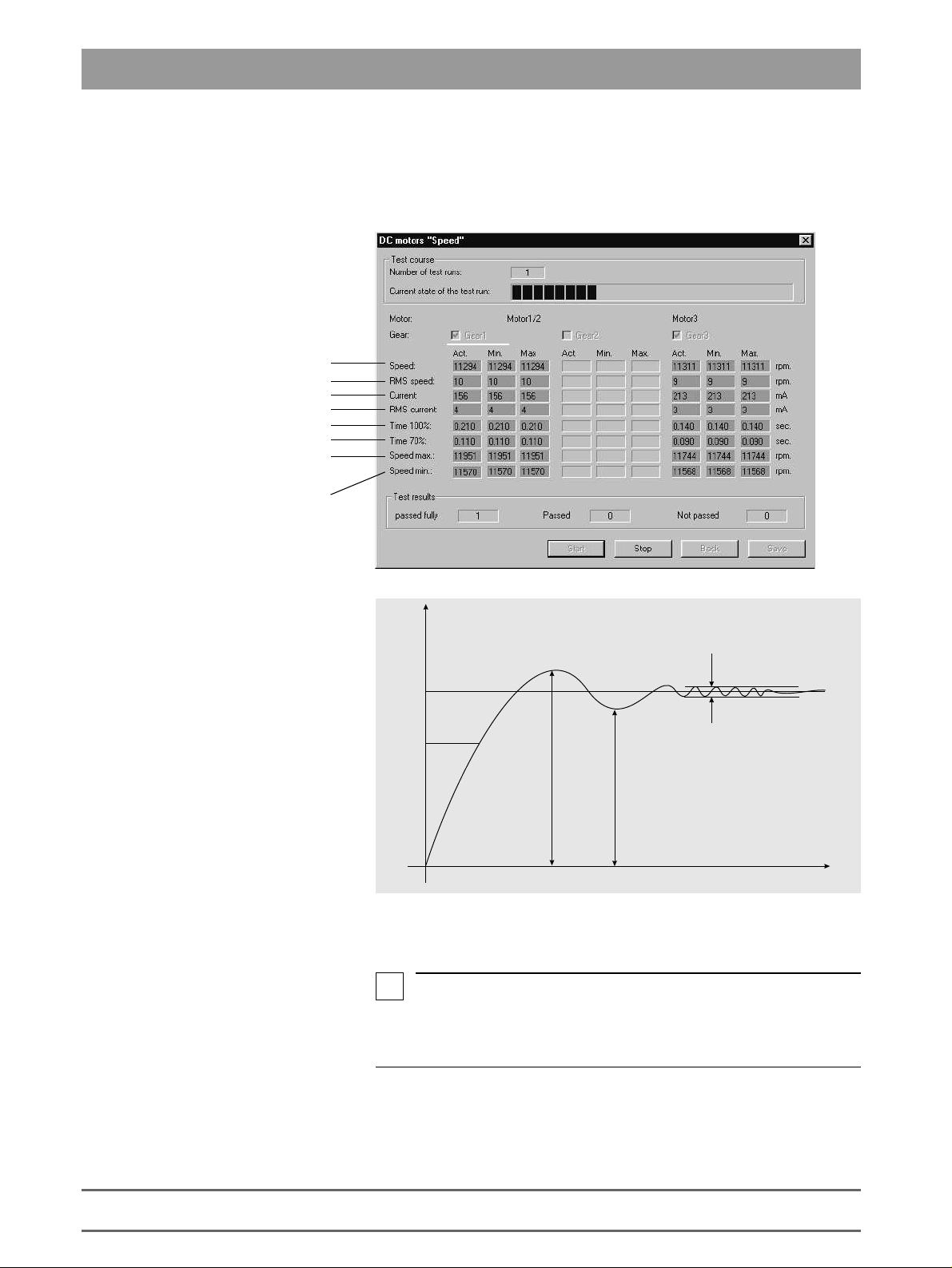
(
2.3.8 DC motors ”Speed”
Purpose of Test:
Fluctuation of speed
Measured motor current
Fluctuation of motor current
Run-up time to 100%
Run-up time to 70%
This test is used to check the two DC motors and their gearings for flawless
functioning in the High-speed mode.
Measured speed
Maximum value of
measured speed
Minimum value of
measured speed
n
r.p.m.)
Max. speed
100%
70%
Procedure
The DC motors are tested by accelerating them from a standing start to working speed and then measuring the relevant data.
i
NOTE
The current is monitored during all measurements. The maximum current
must not stop for longer than 2 seconds; otherwise the test will immediately be
interrupted by an error message.
Min. speed
RMS speed
t (s)
2 - 18
58 35 694 D 3344
D 3344.076.01.04.02 03.2002
Page 31

2.3 Individual Test Points
2.3.9 Scanner test (Scan)
Purpose of Test:
Distance between scanner and measuring point
scanner
scanner
Procedure
This test serves to evaluate the functioning and accuracy of the scanner.
Laser active signal level
Laser inactive signal level
Focal size
Selection of laser diode
Measuring angle
Dimension of noise level
Measuring error
The various required measurements are performed with the help of the calibration phantom.
The functions to be tested can be selected in different variations. If no function
is selected, the Start button remains inactive. Default setting: Test all functions.
2.3
Purpose of Test:
Milling machine temperature
2.3.10Continuous load
This test serves to simulate a maximum load for the power supply and intentionally heat up the entire system.
All loads can be operated simultaneously. The temperature rise of the system
is then measured.
58 35 694 D 3344
D 3344.076.01.04.02 03.2002
2 - 19
Page 32

2.3 Individual Test Points
2.3.11Camera quick test
The camera quick test consists of a series of individual test steps, which can
be carried out both in the specified order and individually.
Experienced service
technicians!
Some test steps are made up of several partial steps, some of which can be
activated individually. These functions should only be used by trained technicians.
Operate by clicking the buttons in the bottom right-hand section of the screen.
2 - 20
When carrying out the test steps in the specified order, it is easier to use only
Next
NOTE
Stop
button.
to stop the process. After clicking
or double
Jump
Next, previous
, the button remains high-
Stop
Stop
D 3344.076.01.04.02 03.2002
or
repeat
then returns to its nor-
58 35 694 D 3344
.
the
i
In many cases "Next" is the same as pressing RETURN.
To select individual test steps, either mark the test step (by clicking it with the
left trackball button, to highlight it in blue) and then select
click on the test step.
Test steps can also be selected by choosing
Select
lighted until the sequence has actually stopped.
mal shading and the sequence can be continued by selecting the corresponding buttons.
Page 33

2.3 Individual Test Points
CAUTION
Side
A
Flat surface
A
Calibration Set A
Select
• "Close Frame Grabber" or
• "Service/Protocol/ Save",
no protocol (log file) is saved.
If a blue dialog box appears, you must select
after following the instructions contained in the box.
If Box A appears, please set Calibration Set A to the 3D camera.
to exit the test run.
Exit
If you exit the test run without selecting the test step
Next
to continue the sequence
2.3
Calibration Set B
58 35 694 D 3344
D 3344.076.01.04.02 03.2002
If Box B appears, please set Calibration Set B to the 3D camera.
B
Side
B
Surface with cross
2 - 21
Page 34

2.3 Individual Test Points
If a yellow results box appears, select
The results of the completed test steps are shown in the LOG box during the
sequence.
The entire LOG box can be viewed by scrolling up/down.
to continue the sequence.
Next
2 - 22
Errors can occur while you are carrying out the test steps. Here, it is important
to follow the instructions.
The camera quick test also includes several
selected in the
i
NOTE
Service functions can only be selected when the test run is stopped.
To end a service function, select a button to continue the test run (e.g.
Service functions consist of:
• Protocol
• Live image
Service
menu and in the pull-down menus.
Service functions
D 3344.076.01.04.02 03.2002
, which can be
Next
58 35 694 D 3344
).
Page 35

Protocol
2.3 Individual Test Points
• Lifting magnet
• LED
• Slide alignment
2.3
Live image
Select
Service/Protocol/Save
run.
To view the protocol, select
Select RETURN to close the protocol (log file) display.
Moving grid = Search image
Int. LED on (standing grid) = Search image with standing grid - visible grid
stripes
Int. LED off (standing grid) = Search image with internal LED deactivated, so
that objects can only be seen when they are illuminated externally.
to create a protocol (log file) during the test
Service/Protocol/Display
.
Lifting magnet
58 35 694 D 3344
D 3344.076.01.04.02 03.2002
The lifting magnet is attracted approximately every 3 sec. for a period of
approx. 1 sec. A clicking sound can be heard.
LED
and
Slide alignment
are not required in the camera quick test.
2 - 23
Page 36

2.3 Individual Test Points
The camera quick test
below.
Camera calibration data obtained from successfully completed tests are
saved and used in the following camera quick test. These data are not used
for camera operation outside the service program, so that the recording process is not affected by the program.
This also means that the camera must be calibrated before it is used in the
camera quick test. This enables the test steps to produce correct results.
Checking the RGB adjustment
rect results without the calibration process being completed.
The test results are indicated in three colors: Green = fully passed, Yellow =
passed, Red = not passed.
Sequence
comprises the test steps (functions) listed
is the only test step which can produce cor-
CAUTION
Failed tests may be due to a badly prepared calibration set. The uniformity of
the powder coating should then be checked.
It should also be noted that test failures may be the result of a faulty camera
cable or PC drawer (Refer to Chapter 4.14 - 4.16).
In the test step labelled
be entered for the serial number (card).
Carrying out the
protocol of the completed tests to be stored as a file in the \CEREC\SYSTEM\SERVICE\PROTOCOLS folder. The file name includes the date and
time of the test as well as the camera serial number, if this was entered in the
Entry of the header data
times, the latest result is entered in the protocol.
Entry of the header data
Closing the frame grabber
test step. If a test step has been carried out several
, a 4-6 figure number must
test step involves generating a
2 - 24
58 35 694 D 3344
D 3344.076.01.04.02 03.2002
Page 37

2.3 Individual Test Points
2.3.12 Info milling unit
This dialog box contains information on the connected milling unit and the
milling times of the burs.
2.3
•
Serial number
•
Milling unit ID
Identifier 0
Identifier 1
Identifier 2
Identifier ??
•
Parallel sided burr (min.)
•
Cone Shaped (Tapered) burr (min.)
bur
•
Total milling time (min.)
•
Total scan time (min.)
– Serial no. of CC PC board
:
= CEREC 3 milling unit / scanner (serial number <5000)
= CEREC inLab milling unit (serial number >5000)
= CEREC 3 milling unit / scanner (serial number >5000)
= no milling machine connected
: – elapsed milling time of parallel-sided bur
: – elapsed milling time of milling unit
: – elapsed scanning time of milling unit
: – elapsed milling time of tapered
58 35 694 D 3344
D 3344.076.01.04.02 03.2002
2 - 25
Page 38

Page 39

CEREC 3
3
Trouble Shooting: Milling Unit
Page 40

List of Contents
Trouble Shooting: Milling Unit
List of Contents
3.1 Device cannot be switched ON. Green LED (Ready for operation) not illuminated .......... 3-5
3.2 No connection to PC / acquisition unit. Software cannot be installed.................................. 3-7
3.3 No air pressure .................................................................................................................... 3-9
3.4 Fan not running. Unit shuts down completely after a short time.......................................... 3-11
3.5 Water pump: Pressure too low ............................................................................................ 3-13
3.6 Defective light barrier........................................................................................................... 3-15
3.7 Door switch. Please close milling chamber door................................................................. 3-17
3.8 Motor locking positions: Problems changing grinders ......................................................... 3-19
3.9 Stepping motors (milling unit). Loss of steps....................................................................... 3-21
3.10 Touch errors ........................................................................................................................ 3-23
3.11 Trouble shooting. Defective CCP board.............................................................................. 3-25
3 - 2
58 35 694 D 3344
D 3344.076.01.04.02 03.2002
Page 41

Personal notes
58 35 694 D 3344
D 3344.076.01.04.02 03.2002
3 - 3
Page 42

3 - 4
LED on power supply unit
V204
V205
V206
V200
Battery
Page 43

CAUTION: Switch OFF the unit before connecting a measuring instrument or replacing parts!
• Line power supply connected to electric outlet?
• Line voltage fuses OK? If not: Always replace both fuses.
• Check line voltage on power supply unit terminal: 100-240V
D 3344.076.01.04.02 03.2002
58 35 694 D 3344
Green LED on power
supply unit
illuminated?
Yes
CC
CC
Turn ON main switch
IV204
Pos.
(42V)
illuminated?
Yes
CC
Lamps
(5V) and
V200
(24V) and
V205
(12V)?
V206
Yes
Board battery
defective/run down
Replace battery
No
No
No
Replace power
Replace board
Replace board
3.1 Device cannot be switched ON. Green LED (Ready for operation) not illuminated
3 - 5
3.1
Page 44

3 - 6
V292
Page 45

CAUTION: Switch OFF the unit before connecting a measuring instrument or replacing parts!
• CAUTION: Fault may also be on PC/acquisition unit.
D 3344.076.01.04.02 03.2002
58 35 694 D 3344
• Check
1. Cable version
configuration
Communication
in the
Check:
• Serial connecting cable
• Interface settings on PC / acquisition Unit
Connection
OK
Yes
No
Connection OK?
Unit OK
2. Radio controlled version
NOTE: When updating software, it may be necessary
to make several (2-3) attempts at starting.
Connect up using the
cable:
No
Connection OK?
Yes
menu.
Replace board
Yes
Unit OK
Replace board
Connection OK?
Yes
No
Check:
Replace cable harness
• Interface settings on PC / acquisition unit
No
Replace cable harness
Unit OK
Connect radio module
V 292 (10V)
illuminated?
Yes
No
Replace board
Replace radio module
3.2 No connection to PC / acquisition unit. Software cannot be installed
3 - 7
3.2
Page 46

3 - 8
Air pressure switch
Air pump
Page 47

CAUTION: Switch OFF the unit before connecting a measuring instrument or replacing parts!
D 3344.076.01.04.02 03.2002
58 35 694 D 3344
• Select Settings/Service/Test selection/Media supply/
Run-up time too short
(0.00)
and
Run-on time too long (0.49)
Run-up time too long (4.50)
and
Run-on time too short
(0.00)
Run-on time too long
Current draw too low (0.00)
Check plug
connections on air
pressure switch.
Replace air pressure switch
Check air hoses Eliminate fault
Check plug
connections on air
pump
Air pump
(* see page 2 - 10) Carry out test
Connect plugs.
Test passed?
Yes
Device OK
Connect plugs.
Test passed?
Yes
Device OK
No
No
Replace air pressure switch
Replace air pump
Current draw too high
(>0.60)
3.3 No air pressure
3 - 9
Replace air pump
Test passed?
Yes
Device OK
No
Replace board
Test passed?
Yes
Device OK
No
Replace cable harness
3.3
Page 48

3 - 10
Fan unit
Page 49

CAUTION: Switch OFF the unit before connecting a measuring instrument or replacing parts!
D 3344.076.01.04.02 03.2002
58 35 694 D 3344
• Select Settings/Service/Test selection/Media supply/
Normal current input level,
Fan unit not running
Current input too low
Check plug connections on fan
Fan unit
Mechanical
unit.
Plug connections OK?
Yes
Are the following LEDs
on?
(L_FAN)
V320
Is
42VDC
X8.1
and
Yes
applied at
and
X8.2
Yes
Replace fan unit
Fan unit
?
(* see page 2 - 10) Carry out test
Remove mechanical
obstruction
No
No
No
Replace CC board
Check line L8.
Connect plugs
Line OK?
Yes
Replace CC board
No
Repair line or replace
cable harness
Current draw too high
Disconnect X8.
No
Replace fan unit
Current draw still too
high?
Yes
Check
short circuits.
X8.1
&
X8.2
for
No
Replace board
Short circuit?
Yes
Replace cable harness
3.4 Fan not running. Unit shuts down completely after a short time
3 - 11
3.4
Page 50

3 - 12
Water pressure switch
Water pump
Page 51

CAUTION: Switch OFF the unit before connecting a measuring instrument or replacing parts!
• Preliminary test: Water tank full. Tank connection button locked in place
• Select Settings/Service/Test selection/Media supply/
Water pump
(* see page 2 - 10) Carry out test
D 3344.076.01.04.02 03.2002
58 35 694 D 3344
Run-up time too short
If the test is not passed, a "damping box upgrade kit" must be ordered. Order No.: 58 85 673
(0.00)
and
Check plug
connections on water
pressure switch
Connect plugs.
Test passed?
Run-on time too long (0.49)
Run-up time too long (4.50)
Run-on time too short
and
Replace water pressure switch
Device OK
(0.00)
Run-on time too long
and / or
Check nozzles on
gearing units and water
water hoses
Remove clogging
current input too high
Run-up time too long
Check water hoses
(suction end)
Remove clogging
and
Current input too low
Current input too low (0.00)
Check connection:
Tank connector Æ tank
Check plug
connections on water
Replace tank connector
Connect plugs.
Test passed?
pump
Yes
Yes
No
No
Replace water pressure switch
Replace water pump
Current input too high
Replace water pump
Test passed?
Yes
Device OK Device OK
3.5 Water pump: Pressure too low
3 - 13
No
Device OK
Replace board
Test passed?
Yes
No
Replace cable
3.5
Page 52

3 - 14
Light barriers
L_B
L_M
L_G
V503
L_B
V703
L_G
V503
L_M
Page 53

CAUTION: Switch OFF the unit before connecting a measuring instrument or replacing parts!
D 3344.076.01.04.02 03.2002
58 35 694 D 3344
• Select Settings/Service/Test selection/Light barriers, …/
Light barriers
Light barriers defective
contaminated?
Check plug connections
V703 (L_G) illuminated?
V503 (L_B) illuminated?
No
No
Replace corresponding
light barrier in G / B/ M axis.
Test passed?
V603 (L_M) illuminated?
No
Yes
Unit OK
CAUTION
stepping motors Total
: May be due to
failure!
Check all plug
connections
Test passed?
Light barriers
No
(* see page 2 - 12) Carry out test.
Remove contamination
Connect plugs
No
Replace board
Test passed?
Yes
Unit OK
Replace board
No
Test passed?
No
Replace
cable
harness
Replace
cable
harness
3.6 Defective light barrier
3 - 15
Yes
Unit OK
Yes
Unit OK
3.6
Page 54

3 - 16
Slide door switch to upper stop
Door switch
Page 55

CAUTION: Switch OFF the unit before connecting a measuring instrument or replacing parts!
D 3344.076.01.04.02 03.2002
58 35 694 D 3344
• Select Settings/Service/Test selection/Light barriers, …/
Test the door switch function:
Door switch/Operating keys
• When the milling chamber door is opened at both contacts, "
• When the milling chamber door is closed at both contacts, "
Check position of door
switch.
Door switch
positioned at upper
stop?
Yes
Unit OK
Slide the door
switch to the
stop.
Door switch
functioning?
Yes
Unit OK
NoNo
Open
" must appear in the display before the door has moved a distance of 5 mm.
Closed
" must appear in the display before the door is locked in place.
Check plug
connections on
door switch.
Connect plugs.
Test passed?
Yes
Unit OK
(* see page 2 - 12) Carry out test
Test door switch using
No
another magnet
Test passed?
Yes
Test magnet in door.
Replace magnet.
Replace door.
Test passed?
Yes
Unit OK
No
No
Replace door switch
Replace board
Test passed?
Yes
Unit OK
No
Replace
cable
harness
3.7 Door switch. Please close milling chamber door
3 - 17
3.7
Page 56

3 - 18
Locking pins
Page 57

CAUTION: Switch OFF the unit before connecting a measuring instrument or replacing parts!
D 3344.076.01.04.02 03.2002
58 35 694 D 3344
• Select Settings/Service/Test selection/Light barriers, …/
• Move grinder to stop position. Replace grinder
Grinder not locked in position (drive
rotates with grinder when attempting to
release the grinder from the drive).
Move grinder to home position.
Locking pins loosened?
Yes
Reposition and seal locking pins
(* see “Checking / Adjusting Stop
positions” on page 1 - 13)
No
spring be pressed in?
Motor stop positions
Check drive.
Can the pressure
(* see page 2 - 13) Carry out a test.
No
Replace gearing
*
Yes
Replace locking pins
(Checking and adjustment of locking
pins
*
see “Checking / Adjusting Stop
positions” on page 1 - 13)
page 1 - 11
see “Replacing the Drive and/or Motor” on
3.8 Motor locking positions: Problems changing grinders
3 - 19
3.8
Page 58

3 - 20
Page 59

CAUTION: Switch OFF the unit before connecting a measuring instrument or replacing parts!
D 3344.076.01.04.02 03.2002
58 35 694 D 3344
• Select Settings/Service/Test selection/
If step losses occur
in stages 1 to 3
Stepping motors
Replace the corresponding stepping
Step losses still indicated?
(* see page 2 - 14) Carry out test
motor
Yes
Replace board
Test passed?
Yes
Unit OK
No
No
Unit OK
Replace cable
harness
Yes
Unit OK
No
Replace milling machine
3.9 Stepping motors (milling unit). Loss of steps
3 - 21
3.9
Page 60

3 - 22
Page 61

CAUTION: Switch OFF the unit before connecting a measuring instrument or replacing parts!
D 3344.076.01.04.02 03.2002
58 35 694 D 3344
• Select Settings/Service/Test selection/
RMS speed too high,
severe speed fluctuations,
low current (< 0.20)
Current too high (> 0.10)
and motor not turning.
Replace DC motor
Current too low (0.00)
DC Motors “Touch”
Replace gearing
Check locking
position.
Movement?
Yes
Check plug
connections on
DC motor
(* see page 2 - 16) Carry out test
No
Replace gearing
Connect plugs.
Test passed?
Yes
Unit OK
No
Replace DC motor
3.10Touch errors
3 - 23
3.10
Page 62

3 - 24
Page 63

CAUTION: Switch OFF the unit before connecting a measuring instrument or replacing parts!
NOTE: If a CCP board is defective, it must be assumed that this is due to a defective motor rather than a fault on the CCP board.
The motors must therefore be checked first of all.
Do the following:
Remove the milling machine PE conductor connector from the bus point.
1.
Connect the measuring device between the milling machine PE conductor connector and the PE conductor bus point (DC voltage > 50 V).
2.
NOTE: In all the following tests:
– No fault: U: < 3 V
– Fault: U: > 3 V
Install a new CCP board.
3.
Switch on the unit.
4.
Carry out a stepping motor test
Defective motor test (interwinding fault to ground). Adjust voltage to approx. 39V.
5.
DC motor test (run-in / load)
If the defective motor (interwinding fault to ground) is tested, a voltage of approx. 22V results.
6.
D 3344.076.01.04.02 03.2002
58 35 694 D 3344
Other causes
If approx. 5V is registered, this indicates a defective light barrier, milling chamber lighting or Hall sensor on one of the DC motors.
7.
Locate the cause by disconnecting the individual leads.
8.
Switch off the unit. Disconnect from the line power supply.
9.
Replace the corresponding part and repeat the test.
10.
11. CAUTION: After repairing the PE conductor - milling machine connection to PE conductor - reconnect the bus point.
3.11Trouble shooting. Defective CCP board
3 - 25
3.11
Page 64

Page 65

4
CEREC 3
Trouble shooting: Acquisition Unit
Page 66

List of Contents
Trouble shooting: Acquisition Unit
List of Contents
4.1 System cannot be switched ON .......................................................................................... 4-7
4.2 PC not booting properly I..................................................................................................... 4-9
4.3 PC not booting properly II .................................................................................................... 4-11
4.4 PC does not respond during switch-on, PC power supply does not start............................ 4-12
4.5 Further PC faults ................................................................................................................. 4-14
4.6 Monitor image flickering....................................................................................................... 4-15
4.7 No monitor display............................................................................................................... 4-17
4.8 Incorrect monitor display format size................................................................................... 4-19
4.9 Monitor: Color shade/gray scale is too weak....................................................................... 4-21
4.10 Trackball not functioning...................................................................................................... 4-23
4.11 Trackball buttons not functioning......................................................................................... 4-25
4.12 Pedal not functioning........................................................................................................... 4-27
4.13 Keyboard not functioning /defective .................................................................................... 4-29
4.14 No camera image ................................................................................................................ 4-31
4.15 Incorrect measuring sensor setting ..................................................................................... 4-33
4.16 Camera calibration: messages ............................................................................................ 4-35
4 - 2
58 35 694 D 3344
D 3344.076.01.04.02 03.2002
Page 67

4.17 Interference at radio interface............................................................................................. 4-37
4.18 No sound or sound level too low ........................................................................................ 4-41
4.19 No Sirocam camera image ................................................................................................. 4-43
4.20 Sirocam camera image interference................................................................................... 4-45
4.21 SIROCAM camera: Incorrect image settings...................................................................... 4-47
4.22 Digital X-ray problems ........................................................................................................ 4-49
58 35 694 D 3344
D 3344.076.01.04.01 03.2002
4 - 3
Page 68

Page 69

Personal notes
58 35 694 D 3344
D 3344.076.01.04.02 03.2002
4 - 5
Page 70

4 - 6
Main switch on rear
LED
of device
L3
Supply line
Keyboard board
X4
DV
DECT supply board
F1/F2
F3
Page 71

CAUTION: Switch OFF the unit before connecting a measuring instrument or replacing parts!
• Line power supply connected to socket?
• Power plug connected?
• Power switch on rear of unit switched ON?
• Power cable attached to PC drawer?
• Keyboard board cable plug X4 connected to DECT power supply board (DV)?
D 3344.076.01.04.01 03.2002
58 35 694D 3344
LED above ON
pushbutton is
Is the LED
when the ON button
is pressed?
Yes
green
Yes
yellow
Unit OK
?
No
fuses. Replace if
necessary.
Is the LED
when the ON button
green
Yes
No
Device OK
Check F1, F2 and F3
No
Replace keyboard board
TT
Disconnect the plug on
the keyboard board
lead and check for 5 V
on socket
X4
(between pins 1 & 6).
5V present?
Yes
Replace keyboard board
TT
No
Check fuse F4
(on DV).
OK?
Replace
supply board
Yes
DECT power
DV
No
Replace fuse F4
4.1 System cannot be switched ON
4 - 7
4.1
Page 72

4 - 8
VGA
Page 73

CAUTION: Switch OFF the unit before connecting a measuring instrument or replacing parts!
• Are the keyboard, trackball and VGA cable connected to the monitor on the PC drawer?
• Is there a disk in the disk drive? If there is, remove it.
• Is the LED above the ON button
Is the boot-up process interrupted when you try
to access the hard disk during the BIOS startup
or
does a "blue screen" error message appear
when Windows is started?
Yes
Boot with restore disk (from PC hardware version
BA) or with bootable image CD-ROM.
yellow or green
? – * see page 4 - 7
No
No
Unit OK
Replace PC drawer
D 3344.076.01.04.01 03.2002
58 35 694D 3344
(
CAUTION
PC booting correctly?
, loss of data!).
Yes
Unit OK
4.2 PC not booting properly I
4 - 9
4.2
Page 74

4 - 10
Table 1:
List of beep-tone error codes
Beep tone sequence Cause of error
1x short OK beep following graphics card test.
no image
If
Is the monitor switched on and the control LED
illuminated?
If not:
Check the monitor voltage supply.
red control LED
If the
cable connecting the graphics card to the monitor.
If the
detects an input signal), check the brightness and
contrast settings of the monitor.
1x long and 3x short The graphics card is defective or not correctly plugged
in to the motherboard.
Repeatedly long The memory module on the motherboard is defective
or not correctly plugged in.
is visible yet, check the following points:
is illuminated, check the VGA
green control LED
is illuminated (monitor
Table 2:
Error messages during boot-up and possible causes of errors:
Error message Cause of error
Floppy disk(s) fail (40): Voltage supply or data cable to floppy not correctly
plugged in or defective. If the cable is OK, the floppy
disk drive may be defective.
Disk Boot Failure, insert System
Disk and press Enter:
Press a key to reboot: Boot sector of hard disk can not be found. Boot with
If the primary master disk was not found: Check the
data cable and voltage supply of the hard disk and the
CD/DVD drive.
restore disk (from PC HW version BA) or with bootable
image CD-ROM. If this fails, replace the PC.
Page 75

CAUTION: Switch OFF the unit before connecting a measuring instrument or replacing parts!
PC power supply starts. PC
begins boot-up procedure.
Boot-up procedure not
correctly completed.
D 3344.076.01.04.01 03.2002
58 35 694D 3344
Does the system detect the graphic
card and display it on the monitor?
Yes
Is a short beep emitted?
Yes
Does the memory test run without
Does one of the error messages from
Correct error as specified in Table 2,
"Error messages during boot-up".
errors?
Yes
the error list appear?
Yes
Yes
No
No
No
Next, * see page 4 - 13 -->
Remove memory module, clean
contact strip
(e.g. rubber eraser).
Plug memory module
in again.
Is the PC now functioning perfectly?
Yes
Unit OK.
a
No
Are the beep tones audible?
Yes
Eliminate errors as outlined in
Table 1,
"List of beep-tone error codes".
Copying a new image
(CAUTION, loss of data!).
Is the PC now functioning
perfectly again?
Yes
Unit OK.
No
No
Next,
see page 4 - 13
*
-->
a
Replace
PC
4.3 PC not booting properly II
4 - 11
4.3
Page 76

4 - 12
4.4 PC does not respond during switch-on, PC power supply does not start
PC does not respond during switchon, PC power supply does not start.
Is the yellow Standby LED at the top
right of the keyboard illuminated?
Yes
Test: Briefly connect
pin5
and
pin9
to X4 on the DECT power supply
board.
Does the PC boot now?
Yes
Keyboard, lead L3 or
lead L4 defective.
Replacement of the defective
component.
No
No
Is a voltage of 230 VAC present at the
power input of the PC?
Yes
Remove and open the PC drawer.
Check the plug connections of the
boards, the memory banks and the
No
No
CPU.
Check the fuses, connectors and
main switch.
Is the blue
cable between
the motherboard
No
and the DECT
Connect the
cable. Can the PC
be booted now?
No
power supply
ATTENTION
! Do not press against
the CPU fan. Temporarily connect the
board plugged in
at both ends?
PC power supply and leads L1, L2
and L3.
Yes
Can the PC now be booted by
pressing the ON key on the
keyboard?
Yes
Yes
Device OK.
Unit OK
Reassemble the PC, slide it into the
Reassemble the PC, slide it into the
acquisition unit and connect the
acquisition unit and connect the
cables.
cables.
Continued on next page
CAUTION: Switch OFF the unit before connecting a measuring instrument or replacing parts!
D 3344.076.01.04.02 03.2002
58 35 694 D 3344
Page 77

CAUTION: Switch OFF the unit before connecting a measuring instrument or replacing parts!
Continued from previous page
a
D 3344.076.01.04.01 03.2002
58 35 694D 3344
Disconnect power cord from PC.
Unplug power supply from drives and
from auxiliary fan.
Disconnect ribbon cable for drives
from motherboard
Plug power cord back in.
Does the PC power supply start?
running?
Yes
Reconnect drives and fans in
succession.
Replace defective component
No
Disconnect power cable from PC.
Remove all boards except for the
graphic card and the DECT power
supply board.
Plug the power cable back in to the
PC.
Does the PC power supply start
running this time?
Yes
Reinstall boards in succession.
Replace defective board.
Reconnect PC.
No
Connect a replacement power supply
to the motherboard and plug in the
power cord.
Does the PC power supply start
running this time?
Yes
Reassemble PC with
replacement power supply.
Install PC in acquisition unit.
No
Replace complete PC.
4.4 PC does not respond when switched on, PC power supply does not start
4 - 13
4.4
Page 78

4 - 14
4.5 Further PC faults
Case of defect/fault How to detect / measure to take
COM port not functioning Try replacing the radio interface with a cable connection.
If this fails, check whether the COM port is enabled in the BIOS. If it is, replace the PC.
No mouse pointer displayed on screen Trackball defective or not connected.
No keyboard input possible Keyboard (keyboard controller) defective or improperly connected.
Check to make sure this fault is not due to bent plug contacts.
Network can not be accessed LED "10" or LED "100" on the slot plate of the network card must always be illuminated green. If not:
• The network cable between the network card and the hub / switch is defective.
• Hub / switch defective (check whether other PCs connected to hub / switch can access the network).
• Network card defective
The "TX Data Act" LED flashes during data communication via the network.
CD-ROM / DVD-ROM missing in list of system
drives (Explorer)
No audio playback Only a musical CD or only a wave file can not be played back:
Data cable and/or voltage supply disconnected and/or defective.
If this is not the case, the drive is defective. Test via BIOS: It must be possible to select the drive.
• Check the software settings.
• Wrong sound card driver installed.
• Cable between CD-ROM / DVD-ROM drive and sound card loose or defective.
• Sound card defective.
• CD-ROM / DVD-ROM drive defective.
No audio playback at all: No audio playback at all:
Test: Connect loudspeaker directly to sound card without the amplifiers on the DECT power supply board. If an audio playback occurs
then, check the cables to and from the DECT power supply board. Then replace these cables or the DECT power supply board if
necessary. If the sound playback functions without the DECT power supply board: Then the loudspeakers (including the lead) or the
sound card are/is defective, or there is an error in the software setting, or the wrong driver was installed for the sound card.
Warning on monitor indicating that fan RPM is too
low
Check whether the fan brushes against an obstruction. If not, replace the fan. If replacement of the fan does not eliminate fault, replace
thePC. In this case, there is probably a defect on the motherboard.
D 3344.076.01.04.02 03.2002
58 35 694 D 3344
Page 79

If the image on the monitor flickers, a distinction must be made between two causes:
a) Flickering of the image brightness and
b) Flickering of the image due to incorrectly set monitor parameters
Adjustment of monitor parameters (all types except PV751)
D 3344.076.01.04.01 03.2002
58 35 694D 3344
• Select the mode
• Press the
The monitor then automatically sets the adjustment parameters.
• Then exit the
The monitor is now correctly adjusted.
For
type PV751
• Set image brightness to
• Set contrast to
If the monitor still flickers following both of these checks, you must then replace
• the monitor (if monitor type PV751 is not involved) and/or
• the assembly "power supply, complete" REF 58 09 889, Rep 58 65 550 (see Chapter ‘6.1.5 Complete power supply unit” ).
SELECT/AUTO
"Quit Windows"
monitors only (see name plate on rear side of monitor):
Start ÖExit in Windows.
Ö
monitor button twice in succession while in this mode.
window with
maximum value of 130
maximum value of 140
"Cancel"
.
4.6 Monitor image flickering
4 - 15
4.6
Page 80

4 - 16
F2
Voltage supply
Monitor
DV
VGA
up to HW Version AB
from HW Version AC
F4
F4
Page 81

CAUTION: Switch OFF the unit before connecting a measuring instrument or replacing parts!
• Are the power supply and the VGA cable connected to the monitor?
• Is the monitor switched on (LED to the right of the ON switch is red or green)?
• Is the PC switched on (LED above the ON button is green)?
• Switch off the monitor and switch it on again after a few moments.
D 3344.076.01.04.01 03.2002
58 35 694D 3344
Monitor dark?
Yes
Is the LED on the
monitor green or red?
Yes
Is the LED
on the
monitor
?
green
Yes
Yes
Is the LED
on the
monitor
red
Yes
No
Press the "Y" and "S" keys to switch on the monitor.
No
Replace monitor
Does monitor carry out a self-test?
Switch off the monitor and disconnect the VGA cable.
Yes
Device OK. Reconnect VGA cable
No
Is the
monitor
ON
Yes
switched
?
No
Switch monitor on. Unit OK.
from HW Version AC
to Hardware Version
Disconnect the power
supply cable and check
for 12V.
No
12V present?
?
Yes
Replace monitor
Check and replace F2 fuse on
p.c.b. (DECT supply board).
DP
Monitor screen ON?
Yes
Unit OK
No
Replace DECT DP
power supply board.
Monitor screen ON?
Yes
Unit OK
No
Replace PC
power supply
Replace
monitor
Check VGA cable.
OK?
Yes
Replace PC drawer
4.7 No monitor display
4 - 17
No
Replace VGA cable.
4.7
Page 82

4 - 18
Page 83

CAUTION: Switch OFF the unit before connecting a measuring instrument or replacing parts!
D 3344.076.01.04.01 03.2002
58 35 694D 3344
• In Windows, select
is set to between 56Hz and 75Hz.
• When the resolution is set to exactly 1024x768 (VESA XGA), press the SELECT/AUTO button twice to automatically adjust the monitor to the correct setting.
If this does not happen, replace the monitor.
• When using screen resolutions lower than 1024x768 (VESA XGA): Press the MENU button.
Then press the SELECT/AUTO key
If this is not possible, replace the monitor.
START -> SETTINGS-> CONTROL PANEL> DISPLAY-> SETTINGS
once.
Select
for Full screen mode.
to check that the resolution is
set to above 1024X768 (VESA XGA) and that the refresh rate
not
4.8 Incorrect monitor display format size
4 - 19
4.8
Page 84

4 - 20
Brightness
Contrast
Page 85

CAUTION: Switch OFF the unit before connecting a measuring instrument or replacing parts!
D 3344.076.01.04.01 03.2002
58 35 694D 3344
• Check Windows color pallet setting in the
In the color pallet, a setting between 16Bit (High Color = 65536 colors) and 24Bit (True Color = 16777216 colors) must be selected (only applies to 3dfx Voodoo3 graphics card). If other
graphics cards are used, the color pallet setting must be > 16Bit.
• Adjust the monitor brightness to 140 and the contrast to 130.
Start -> Settings -> Control -> Display -> settings
.
Poor color shading/
gray scale?
Yes
Replace VGA cable.
Poor color shading/
gray scale?
Yes
No
Unit OK
Replace monitor.
Poor color shading/
gray scale?
No
Unit OK
Yes
Replace PC drawer.
4.9 Monitor: Color shade/gray scale is too weak
4 - 21
4.9
Page 86

4 - 22
PS/2 plug
Trackball
PS/2 plug
Keyboard
Trackball
Page 87

CAUTION: Switch OFF the unit before connecting a measuring instrument or replacing parts!
D 3344.076.01.04.01 03.2002
58 35 694D 3344
Switch device OFF and
ON again.
Is the trackball
Yes
Unit OK
No
functioning?
Is the PS/2 plug for
the trackball properly
connected?
Keyboard
Yes
Yes
No
Have the PS/2 plugs
for the keyboard and
the trackball been
switched?
Swap PS/2 plugs.
Device OK.
Connect trackball PS/2
No
Trackball functioning?
Yes
plug correctly.
Yes
Unit OK
No
No
Attach replacement
trackball or mouse to
the PC drawer with a
PS/2 plug and test.
Trackball/Mouse
functioning?
Yes
Replace trackball
No
Replace
PC drawer
4.10Trackball not functioning
4 - 23
4.10
Page 88

4 - 24
Keyboard
board
TT
L7
L3
DP
Page 89

CAUTION: Switch OFF the unit before connecting a measuring instrument or replacing parts!
• Check whether trackball is functioning
• Disconnect the pedal and reboot the PC.
• Check continuity of keyboard board lead L3 (between DECT supply board DP and keyboard board TT).
• Check trackball power supply.
D 3344.076.01.04.01 03.2002
58 35 694D 3344
Check for short circuits of the two pedal
sockets and the pedal
Short circuit occurred?
Yes
Replace pedal or lead L3 between DECT
supply board DP and keyboard board
TT
Trackball buttons functioning?
Yes
Unit OK
Check continuity on L7 keyboard cable
between trackball and keyboard board.
No
OK?
Yes
Replace keyboard board
TT
No
Repair lead L7 or
Replace trackball
.
No
Replace keyboard board
TT
4.11Trackball buttons not functioning
4 - 25
4.11
Page 90

4 - 26
Right-handed
Left-handed
Pedal lead
L8
Page 91

CAUTION: Switch OFF the unit before connecting a measuring instrument or replacing parts!
• Refer to "Changing from Right-Handed to Left-Handed Operation" in the Operating Instructions for the Acquisition Unit.
Software changeover via
• Is the plug of pedal lead L8 connected properly?
• Is the pedal not mechanically obstructed?
Start -> Settings -> Control -> Mouse
Pull off the plug L8.
Both trackball buttons
functioning?
No
Both trackball buttons
functioning?
Yes
.
No
Replace keyboard board (TT)
D 3344.076.01.04.01 03.2002
58 35 694D 3344
Yes
Repair/replace pedal lead
(Microswitch, compl.)
Repair/replace pedal lead
(Microswitch, compl.)
4.12Pedal not functioning
4 - 27
4.12
Page 92

4 - 28
Keyboard
PS/2 plug
Trackball
PS/2 plug
Keyboard
L3 DECT
Page 93

CAUTION: Switch OFF the unit before connecting a measuring instrument or replacing parts!
• Check whether the trackball and keyboard PS/2 plugs are properly connected to the PC drawer and not in the wrong sockets (switched).
• Check continuity on L3 cable to the keyboard board.
D 3344.076.01.04.01 03.2002
58 35 694D 3344
LED above ON button
green
Yes
?
Replace keyboard
No
Check the supply voltages at the
output socket of the DECT power
supply board (X4.1: +5V and
X4.2:+12V).
Supply voltage OK?
Yes
Check the supply voltages at the
PS/2 output socket
(PIN 4: +5V and PIN 3: GND) on the
PC drawer.
Supply voltage OK?
Yes
Replace keyboard
No
No
Replace DECT power supply board
Keyboard functioning?
Yes
Device OK
Replace PC drawer.
Keyboard functioning?
Yes
Unit OK
No
No
Replace keyboard
Replace keyboard
4.13Keyboard not functioning /defective
4 - 29
4.13
Page 94

4 - 30
Page 95

CAUTION: Switch OFF the unit before connecting a measuring instrument or replacing parts!
Is the camera cable properly connected to the camera and the image acquisition (Frame Grabber) card in the PC drawer?
1.
For versions up to IDS 2001 only:
2.
Recorded image displayed without camera live image?
If YES, check Windows color pallet setting via
Color = 16777216 colors) must be selected. Change the setting if necessary. It is permissible to select 32Bit on Pentium
Only for versions up to IDS 2001:
3.
If there is still no live image, check whether the screensaver was activated.
If the answer is YES, select
Carry out camera quick test (
4.
Connect replacement camera cable.
5.
If this fails, connect a replacement camera.
If this also fails, install new software.
If there is still no camera image, the image acquisition
CEREC fault message appears when the camera should be activated? YES: install new software.
6.
If no camera image appears, replace the Frame Grabber card.
Settings -> Control -> Display -> Screensaver
see page 2 - 20).
*
Start -> Settings -> Control -> Display -> Settings
(
). Then accept this setting and reboot the PC if necessary.
None
Frame Grabber) card in the PC drawer is probably defective. Replace the Frame Grabber card.
(
. In the color pallet, a setting between 16Bit (High Color = 65536 colors) and 24Bit (True
®
III systems.
D 3344.076.01.04.01 03.2002
58 35 694D 3344
4.14No camera image
4 - 31
4.14
Page 96

4 - 32
Page 97

CAUTION: Switch OFF the unit before connecting a measuring instrument or replacing parts!
D 3344.076.01.04.01 03.2002
58 35 694D 3344
• Check whether the lifting magnet in the
Lifting magnet activated?
Yes
No
Recalibrate 3D camera
(Refer to the acquisition unit
3D camera
is briefly activated during the measuring phase. A clicking sound should be heard.
Connect replacement
camera cable.
Lifting magnet
activated?
No
Connect the
replacement camera to
test it.
Lifting magnet
No
activated?
Yes
Replace camera cable and
recalibrate 3D camera
recalibrate 3D camera
Yes
Replace and
Replace Grabcer* image acqn. card
*Frame Grabber card
operating instructions)
• Badly adjusted optical impressions may be due to shaking of the camera. The stored optical impression may, however, be OK despite shaking of the camera.
4.15Incorrect measuring sensor setting
4 - 33
4.15
Page 98

4 - 34
Page 99

CAUTION: Switch OFF the unit before connecting a measuring instrument or replacing parts!
There are two types of error messages which can occur during camera calibration:
– Type 1 are warnings which should be treated seriously. It is possible to temporarily accept these errors by selecting OK and then continue with the calibration process.
– Type 2 are errors which force the calibration process to stop without the calibration data being saved.
The texts of the error messages give instructions on what to do. Observe the following:
• Prepare the calibration set properly.
• Slide the calibration set up to the stop.
• Ensure that the camera is kept clean (see acquisition unit operating instructions and 3D camera calibration instructions).
If "Image too small.. " is displayed, try to reposition the prism tube in relation to the camera in order to avoid any possible image loss.
If it is not possible to prevent errors from occurring by carrying out the suggested measures, the 3D camera, camera cable or PC drawer may be defective.
First, test the replacement 3D camera. If this does not help, test a replacement camera cable. If this still does not help, test a replacement PC drawer.
The Service program can also be used for diagnosis and documentation purposes.
Select
Settings / Service / Camera quick test
to test the camera and to record the results in a protocol (
see page 2 - 20 and ff.).
*
D 3344.076.01.04.01 03.2002
58 35 694D 3344
4.16Camera calibration: messages
4 - 35
4.16
Page 100

4 - 36
Milling Unit
Radio module
 Loading...