


99-13
18131)
INSTRUCTIONS
FOR USING
THE SINGER PORTABLE
ELECTRIC SEWING MACHINE
No. 99-13
(ATTACI liVlliN 13 I ¿0360)
WITH KNEE CONTROL
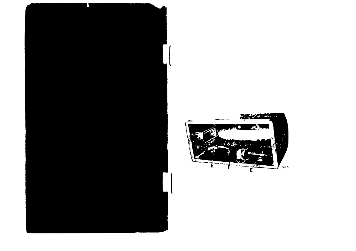
Fia. 1. KnKH I.kIVER IÍÍ PuRlTION IN CoVKU
AfUir miioviiiK llie cover, remove (he knee lever
(F, Fig. 1) from (he two cleats (K, Fig. 1).
NEVER USE OIL ANYWHERE ON THE MOTOR —
Lubricate only with Singer Motor Lubricant and use it
only in the two grease tubes provided for that purpose,
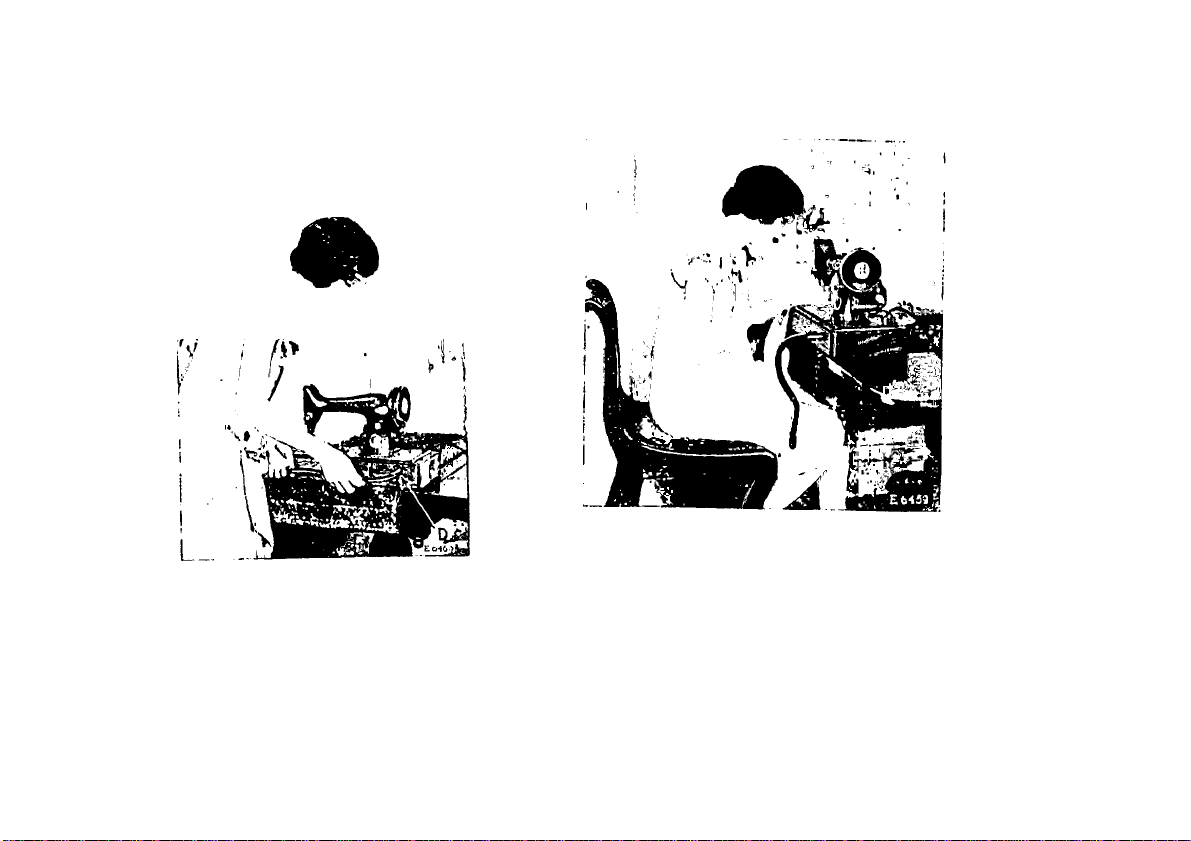
Ilokl Uio lever iii the hurizoïilal position as sliown
in h'ig. 2, and push the soeket of the lever over
To Adjust the Knee Lever
Fia. 2. Pl.\cing Knee Lever in l’osmoN
the stud (n, Fig. 2). Allow the lever to dnip
into the vertie.al i)Osilion as shown in Fig. 2, page 2.
Fiü. 3. Knee Lever in Position Heady
FOU ül'ERATIÜN
Motor can be Operated on Either Alternating
Current or Direct Current
The ctccli'ii! iiiulor, which is located at the. liaclc
of Ihu machine, can he opcrateil on oil her altcniat-
ing emrent or direct enrrent, as desiiv<l. 'riie
slnndard windiiigs of tlio motor are for ill) volts,
and motors can he fnrnislicd tor any voltage hetweon
100 and 250.
¡Special motors for 32 volts direct current, and
for 50 volts alternating enrrent and direct cuiTont,
have also hcen developed ami aie availahle.
Points to Determine before Connecting
Motor to Electric Service Line
Obtain the following information from the Elec
tric Light ftompany which supplies the electric
current for the circuit to w'hich the mohir is to
he connected:
1. AN'hat is the voltage? 'I'he voltage must he
within the range stamped on the motor nameplate.
2. If the current is alternating, what is the num-
her of cycles? 'I'he mimher of cycles must he
within the range stamped on the motor name plate.
The voltage of any circuit and, if alternating
current, the number of cycles, can he verified by
looking at the name plate on service watt meter
installed by the local Electric Light Company.
Enwind the. electric cord, screw the plug at the
cnil into an electric light socket and turn on the
switch.
To Make the Electrical Connection
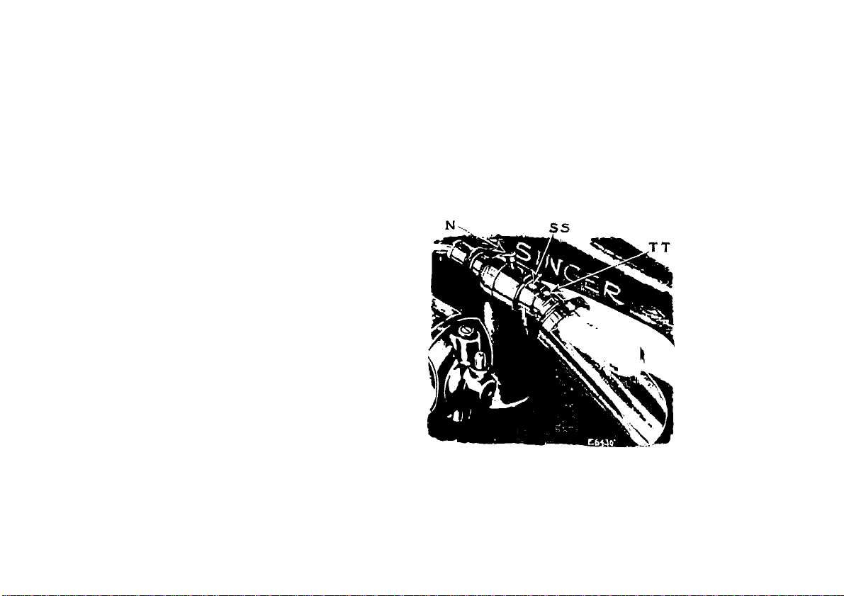
To Turn Singerlight “On” or “Off”
lieach over the toji of the machine and move
the switch lever (N, Eig. -Ij to the right or left a.s
tlcsil'dll.
4
6
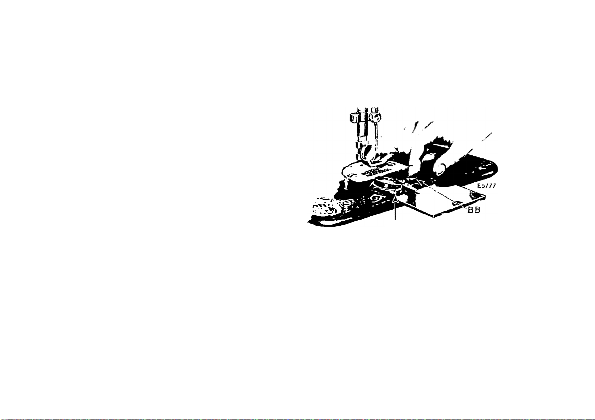
To Remove and Replace the Bulb
To remove the hull), hold the Biogerlight socket
tighllj' with one hand and with the other hand
turn I he shade halfway around until the pin tBB,
hig. ll for the shade is in the slot of the shaile, then
gently slip the shade olT and allow it to hung free as
shown in Kig. -1.
Do not attemi)t to unscrew the hiilh. It is of
the hayonet and socket type and does not unscrew.
1‘ress the hull) into the socket anil at the same
time turn it until the hull) i>in 1'1’T, Kig. 4) is out
of the notch in the socket, then withdraw the
hull) and shade.
To insert a new hull), pass the hull) through the
collar of the shade with the slot of the shade up
ward. Hold the socket tightly with one hand and
at the same time with the other hand pre.ss the
l)ulh into the socket with the hull) i)in (TT, kig.
4) in the slot and turn it until this pin is in the
notch. 'I'lien slip the shade over the socket, the pin
tS.S, I’ig. 4) for the shade entering the slot of the
shade. See that the pin (SSJ is in the groove of
the shade and turn the shade halfway around, or
until it is at the top.
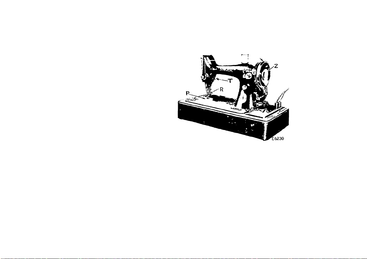
'J’o prevent injury to the presser foot (R, Tig. 5)
and feed (P, Tig. .5), raise the presser foot (R)
hy means of the presser bar lifter (T, ]'’ig. 5).
Us
To Operate the Machine
0. Tuont Vitiw ui«* TUB Macuinu
PlilCU a piece of cloth under the presser foot
and then let the foot down upon it.
Turn on the electric current and lightly press the
knee lever to the right. As you press haidcr against
the knee lever, the speed of the machine is increa.seil,
(he speed being eonirollcd entirely by the degree to
which the knee lever is pushed over. Operate the
machine in this way witliout being threaded, until
you have become accustomed to guiding the ma
terial anil operating the knee lever.
'I'lic Inilillice wheel iiniisl always turn over towaril
yon.
Do not rnii the luaelhno with the presser foot
resting on the Cecil without cloth nniler the jnesser
toot.
Do not run the niaehine when both bobbin ease
anil neeillo are Ihreaileil unless there is lualerial
umler the [ire.s.ser toot.
Do not try to help the jnaehine by [Killing the
fabric lest you bend Ihe needle. 'I’he inaehine feeds
the work without assistauee.
The slide over the bobbin ease should be kept
elo.sed when the inaehine is in o|)eration.
CAUTION
When through with your sewing, always
turn off the electric switch at the lamp socket.
To Ensure Perfect Action of the Machine
To Take Out the Bobbin
Draw to the left the slide in the bed of the
inaehine and [iress the forelinger of the right hand
A A
To Pack Up the Outfit
Heniove the [ilng from the electric light socket
and coil the electric cord around the uiachine.
liaise the knee lever to a liorinontal position, re
move it and replace it into the cleats (li, Kig. 1,
page 1) in the cover, lleplace the cover and lock it.
Fio. 5. Tiiif: Boudin
u|ion the bobbin ejector (Bli, Pig. (>); this will
rai.se the bobbin so that it can be easily taken out.
10
To Wind the Bobbin
lb iri iicec.ssiiU'y bo undiM’sliMul ilio slop iuol.i«)n
C/j, l’’ig. 5, pagò 7) by wliioh Lhu balaiioc wheel
E»-05
MACiiiNe 'l'uite.vuKU euu WiNeise 'niK Uüuuik
(U, Fig. 5) ean l)e reloiised when leituired, bhus
peniiil.tiiig the winding of bobbiits wilhout. iiminng
llie slilehing meehanisin. It also allows yon
to wind bobbins wilhonb removing parlially sewn
work and wilhont nnthreading the machine.
To I'elease the balance wheel (U, Fig. 5), turn the
stop motion screw ('/, Fig. 5) over toward yon.
IL is iiocossury to hold the bulanco wiieol >viulc
loosening the stop inoLiou screw.
ooscning me SLop nioiiou ai.iv.«.
I Unte the bobbin on the bobbin winder spindle
(V'V I'ig. S, page 11) and push it up closely against
the shoulder, liaving the small jiin in llie spindle
enter the hole in the side of the hobbin. Fnt the
spool of thread on the spool |im (1, Fig. 7). I ass
the end of the thread into the thread guide (2, Fig.
7) then np into the lower eyelet (3, Fig. 8) of the
hobbin winder thread guide, into the notch (1, F'ig.
11
£5780
Flo. S, \Vr^fJ>l^ao TUB liouui.v
8) ami piuss the tlinuid Ihrongii tlu* link; in tliL* loft-
side of the liobbin (5, Fig. 8), from the inside. I’re.ss
I he bobhin winder pulley (J.I, Fig. 8) tiown on the
halunee wheel hiih, and the latch (1111, l-'ig. 8) will
drop down and hohl it. 'I'lien start the lialanee
wheel in motion the same as for sewing.
The end of the thread niiist he held hy the hand
until a few coils are woimd and should then he
hioken oil. When siiilieient thread lues lu'en woiiinl
upon the bobhin, the bobbin winder is antomatieally
reloxsed from tlio balance wheel.
Jf the pressiiie of the rubber ring (,U, l-’ig. 8)
agaiiisl tile hub of the balance wheel is insullieienl
for winding the bobbin, loosen the adjusting screw
(GG, Fig. S) and [iress the bohhin wiiuler lightly
until the rnhher ring is in contact with the hub of
the balance wheel; then tighten the screw.
i
Ilukl the bobbin between the thuinl) ami fovc-
linger of I he left hand, tlie Uneail leacling on top
fi-oni the rijilit lowaiil the left, as shown in Fig. 9.
13
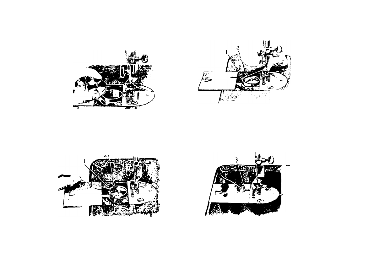
To Replace the Bobbin
i;s
FlU. 1). UE1M..»C1.S'U the tiOUUIN
I’laee the bobbin into the bobl)in emse and draw
the thread into the slot (1, Fig. 10; in t-l'n bobbin
ease, as .sliown below.
nao
Oraw the thread backward between the bobbin
case ami the tension siiring until it reaches the
l*u:. H. BoGiiiji Case n*mtBAUED
notch (2, Fig. 11) then pnll thè thread toward thè
righi, as shown in Fig. 11.
W'hcn clo.sing thè slide, see that thè thread is in
thè slot (3, Fig. 12) in thè right edge of (he slide, as
.shown below,
Fig. io. Tuiie.i.oiNa tue Bouuis Case
nsr.*
Fu;. 12. UndEIC TuUEAUlNO Co.Ml'LE'rKI)
1-1
15
'I'uni Uic bivlmuio wliocl ovei' loward you until Iho
iiooillo l):u‘ moves u|) l.o ils lushest point, loosen
tin! (liiiinb screw (ICIi, I’ig. 7, page 10) in the nceille
cliimp (1)1), Fig. 7), limi put tin: iioeillo up into
the clamp as fiir ¡is it will go, with ils Hat side
towaiil the right, then tighten the thumb .screw.
To select the eorieet needle see page 4cS.
To Set the Needle
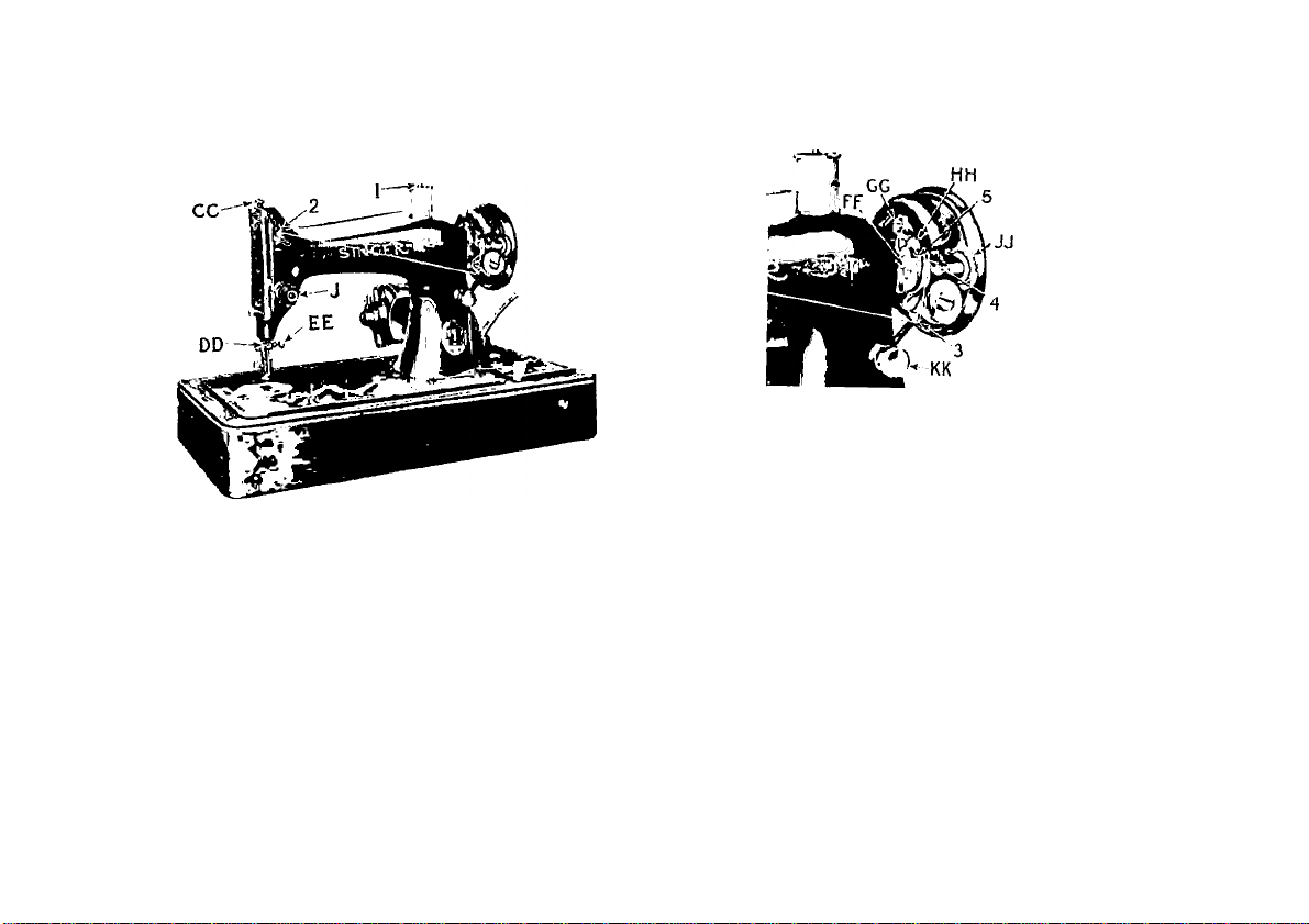
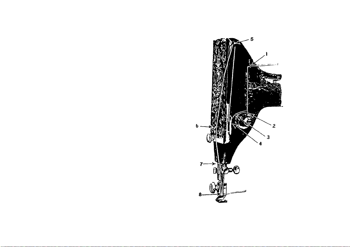
To Thread the Needle
See l‘'i*i. IS ON TUB Foi.lo\vjno Paob
Turn the balance wheel over towaid you until the
thread take-up lever {,5) is rai.sed to its highest
])oint. 1‘laee the spool of threail on the spool pin
at the top of the Jiiachine, lead the thread into the
Ihread guide (1) at the left, down, uiulcr and from
right to left between the tension discs (2), into the
small wire siiring (3), under the t.hrcail regulator (-1.)
at the left (not through the eye in the thread
regulator), up innl from right to left through the
hole in the end of the thread take-up lever (5), tlown
into the eyelet (ti), into the lower wire guide (7),
then from left to right through the eye of the
neeille (8).
Diaw about two inches of thread through the
eye of the jicedle with which to commence sewing.
Instructions for threading the machine for darning
and for embroidery are given on pages 41) and 47.
, Eó-HS
i'lij. 13. TiiJtK.1
.VDZN<} TUB
 Loading...