


 Loading...
LITHOSTAR MODULARIS
SP
Troubleshooting Guide
System
Troubleshooting Guide
© Siemens AG 2000
The reproduction, transmission or use of this document or its contents is not permitted without express written authority. Offenders will be liable for damages. All rights, including rights created by patent grant or registration of a utility model or design, are reserved.
Print No.: SPL1-130.840.01.05.02 |
English |
Replaces: SPL1-130.840.01.04.02 |
Doc. Gen. Date: 04.05 |

2 |
Revision / Disclaimer |
Document revision level
The document corresponds to the version/revision level effective at the time of system delivery. Revisions to hardcopy documentation are not automatically distributed.
Please contact your local Siemens office to order current revision levels.
Disclaimer
The installation and service of equipment described herein is to be performed by qualified personnel who are employed by Siemens or one of its affiliates or who are otherwise authorized by Siemens or one of its affiliates to provide such services.
Assemblers and other persons who are not employed by or otherwise directly affiliated with or authorized by Siemens or one of its affiliates are directed to contact one of the local offices of Siemens or one of its affiliates before attempting installation or service procedures.
LITHOSTAR MODULARIS |
SPL1-130.840.01.05.02 |
Page 2 of 138 |
Siemens AG |
|
04.05 |
CS PS 24 |
Medical Solutions |

Table of Contents |
3 |
1 _______ General ________________________________________________________ 7
Safety Information and Protective Measures . . . . . . . . . . . . . . . . . . . . . . . . . . . . . . . . . . 7 Applicability and Regulations for the Country Organizations . . . . . . . . . . . . . . . . . . . 7
Required Tools and Test Equipment . . . . . . . . . . . . . . . . . . . . . . . . . . . . . . . . . . . . . . . . 9
Required Aids and Documents . . . . . . . . . . . . . . . . . . . . . . . . . . . . . . . . . . . . . . . . . . . |
10 |
Product-specific Information . . . . . . . . . . . . . . . . . . . . . . . . . . . . . . . . . . . . . . . . . . . . . 11
Modularis . . . . . . . . . . . . . . . . . . . . . . . . . . . . . . . . . . . . . . . . . . . . . . . . . . . . . . . . . 11
Modularis Vario . . . . . . . . . . . . . . . . . . . . . . . . . . . . . . . . . . . . . . . . . . . . . . . . . . . . 11
2 _______ LITHOSTAR MODULARIS Error List _______________________________ 13
Info, E00 and E99. . . . . . . . . . . . . . . . . . . . . . . . . . . . . . . . . . . . . . . . . . . . . . . . . . . . . . 14 Water System, E10-E12 . . . . . . . . . . . . . . . . . . . . . . . . . . . . . . . . . . . . . . . . . . . . . . . . . 15 Water System, E14-E15 . . . . . . . . . . . . . . . . . . . . . . . . . . . . . . . . . . . . . . . . . . . . . . . . 16 Controls, E20-E21 . . . . . . . . . . . . . . . . . . . . . . . . . . . . . . . . . . . . . . . . . . . . . . . . . . . . . 17 Controls, E22-E25 . . . . . . . . . . . . . . . . . . . . . . . . . . . . . . . . . . . . . . . . . . . . . . . . . . . . . 18 Controls, E26-E29 . . . . . . . . . . . . . . . . . . . . . . . . . . . . . . . . . . . . . . . . . . . . . . . . . . . . . 19 Monitoring, E31-E34. . . . . . . . . . . . . . . . . . . . . . . . . . . . . . . . . . . . . . . . . . . . . . . . . . . . 20 Monitoring, E40-E48. . . . . . . . . . . . . . . . . . . . . . . . . . . . . . . . . . . . . . . . . . . . . . . . . . . . 21 Monitoring, E49-E54. . . . . . . . . . . . . . . . . . . . . . . . . . . . . . . . . . . . . . . . . . . . . . . . . . . . 22 High Voltage Circuit, E60 - E67 . . . . . . . . . . . . . . . . . . . . . . . . . . . . . . . . . . . . . . . . . . . 23 High Voltage Circuit, E68 - E74 . . . . . . . . . . . . . . . . . . . . . . . . . . . . . . . . . . . . . . . . . . . 24 High Voltage Circuit, E75 - E78 . . . . . . . . . . . . . . . . . . . . . . . . . . . . . . . . . . . . . . . . . . . 25 Internal Errors, E80-E89. . . . . . . . . . . . . . . . . . . . . . . . . . . . . . . . . . . . . . . . . . . . . . . . . 26 Ultrasound, E90-E93 . . . . . . . . . . . . . . . . . . . . . . . . . . . . . . . . . . . . . . . . . . . . . . . . . . . 27 Displays on the D3 Board. . . . . . . . . . . . . . . . . . . . . . . . . . . . . . . . . . . . . . . . . . . . . . . . 28
Text on the Console . . . . . . . . . . . . . . . . . . . . . . . . . . . . . . . . . . . . . . . . . . . . . . . . . . . . 29 "Chip card invalid" . . . . . . . . . . . . . . . . . . . . . . . . . . . . . . . . . . . . . . . . . . . . . . . . . . 29 LITHOSTAR MODULARIS SIEMENS . . . . . . . . . . . . . . . . . . . . . . . . . . . . . . . . . . . 29
Missing Isocenter Cross on the Ultrasound System. . . . . . . . . . . . . . . . . . . . . . . . . . . . 30
3 _______ Service Software _______________________________________________ 31
(Hyper) Terminal Program . . . . . . . . . . . . . . . . . . . . . . . . . . . . . . . . . . . . . . . . . . . . . . . 31
German WINDOWS 95/98/NT . . . . . . . . . . . . . . . . . . . . . . . . . . . . . . . . . . . . . . . . . . . . 32
English Windows 95/98/NT . . . . . . . . . . . . . . . . . . . . . . . . . . . . . . . . . . . . . . . . . . . . . . 33
Working with the (Hyper) Terminal Program . . . . . . . . . . . . . . . . . . . . . . . . . . . . . . . . . 34 Select Option: h . . . . . . . . . . . . . . . . . . . . . . . . . . . . . . . . . . . . . . . . . . . . . . . . . . . . 34 Select Option: p . . . . . . . . . . . . . . . . . . . . . . . . . . . . . . . . . . . . . . . . . . . . . . . . . . . . 35 Select Option: d . . . . . . . . . . . . . . . . . . . . . . . . . . . . . . . . . . . . . . . . . . . . . . . . . . . . 35 Select Option: e . . . . . . . . . . . . . . . . . . . . . . . . . . . . . . . . . . . . . . . . . . . . . . . . . . . . 36 Select Option: t . . . . . . . . . . . . . . . . . . . . . . . . . . . . . . . . . . . . . . . . . . . . . . . . . . . . . 36 Select Option: c. . . . . . . . . . . . . . . . . . . . . . . . . . . . . . . . . . . . . . . . . . . . . . . . . . . . . 37 Select Option: a/b . . . . . . . . . . . . . . . . . . . . . . . . . . . . . . . . . . . . . . . . . . . . . . . . . . . 39
Siemens AG |
SPL1-130.840.01.05.02 |
Page 3 of 138 |
LITHOSTAR MODULARIS |
Medical Solutions |
04.05 |
CS PS 24 |
|

4 |
Table of Contents |
Select Option: i . . . . . . . . . . . . . . . . . . . . . . . . . . . . . . . . . . . . . . . . . . . . . . . . . . . . . 39 Select Option: u . . . . . . . . . . . . . . . . . . . . . . . . . . . . . . . . . . . . . . . . . . . . . . . . . . . . . 39 Select option: r. . . . . . . . . . . . . . . . . . . . . . . . . . . . . . . . . . . . . . . . . . . . . . . . . . . . . . 42 Select Option: s . . . . . . . . . . . . . . . . . . . . . . . . . . . . . . . . . . . . . . . . . . . . . . . . . . . . 42 Software Download with Windows 95 / 98 / NT. . . . . . . . . . . . . . . . . . . . . . . . . . . . . 43 Select Option: 0 . . . . . . . . . . . . . . . . . . . . . . . . . . . . . . . . . . . . . . . . . . . . . . . . . . . . . 44 Text after Replacing the D3 Board . . . . . . . . . . . . . . . . . . . . . . . . . . . . . . . . . . . . . . 44
LITHOSTAR MODULARIS Control Panel . . . . . . . . . . . . . . . . . . . . . . . . . . . . . . . . . . . 47
4 _______ LITHOSTAR MODULARIS ________________________________________ 49
LITHOSTAR MODULARIS Parts Overview . . . . . . . . . . . . . . . . . . . . . . . . . . . . . . . . . . 49
Shock Wave Head . . . . . . . . . . . . . . . . . . . . . . . . . . . . . . . . . . . . . . . . . . . . . . . . . . . . . 51
Shock Wave Head Cover Panels . . . . . . . . . . . . . . . . . . . . . . . . . . . . . . . . . . . . . . . 51
Removing the Shock Wave Head . . . . . . . . . . . . . . . . . . . . . . . . . . . . . . . . . . . . . . . 52
Installing the Shock Wave Head . . . . . . . . . . . . . . . . . . . . . . . . . . . . . . . . . . . . . . . . 54
Replacing the Isocenter Phantom . . . . . . . . . . . . . . . . . . . . . . . . . . . . . . . . . . . . . . . . . . 57
Cooling Unit. . . . . . . . . . . . . . . . . . . . . . . . . . . . . . . . . . . . . . . . . . . . . . . . . . . . . . . . . . . 59 Checking the Cooling Unit . . . . . . . . . . . . . . . . . . . . . . . . . . . . . . . . . . . . . . . . . . . . . 59 Replacing the Cooling Unit . . . . . . . . . . . . . . . . . . . . . . . . . . . . . . . . . . . . . . . . . . . . 59 Filling the Cooling System . . . . . . . . . . . . . . . . . . . . . . . . . . . . . . . . . . . . . . . . . . . . . 59 Filling the Coupling System . . . . . . . . . . . . . . . . . . . . . . . . . . . . . . . . . . . . . . . . . . . . 60 Emptying the Cooling System with the Old Pump (2/Fig. 10) . . . . . . . . . . . . . . . . . . 60 Emptying the Cooling system with the New Pump . . . . . . . . . . . . . . . . . . . . . . . . . . 61 Emptying the Coupling System . . . . . . . . . . . . . . . . . . . . . . . . . . . . . . . . . . . . . . . . . 61
Hose Pump Head in the Coupling System . . . . . . . . . . . . . . . . . . . . . . . . . . . . . . . . . . . 62 Removing the Hose Pump Head . . . . . . . . . . . . . . . . . . . . . . . . . . . . . . . . . . . . . . . . 62 Installing the Hose Pump Head . . . . . . . . . . . . . . . . . . . . . . . . . . . . . . . . . . . . . . . . . 62
Hose Pump Head in the Cooling System . . . . . . . . . . . . . . . . . . . . . . . . . . . . . . . . . . . . 63 Removing the Hose Pump Head . . . . . . . . . . . . . . . . . . . . . . . . . . . . . . . . . . . . . . . . 63 Installing the Hose Pump Head . . . . . . . . . . . . . . . . . . . . . . . . . . . . . . . . . . . . . . . . . 63
IWAKI Cooling Pump . . . . . . . . . . . . . . . . . . . . . . . . . . . . . . . . . . . . . . . . . . . . . . . . . . . 64
Removal . . . . . . . . . . . . . . . . . . . . . . . . . . . . . . . . . . . . . . . . . . . . . . . . . . . . . . . . . . 64
Installation . . . . . . . . . . . . . . . . . . . . . . . . . . . . . . . . . . . . . . . . . . . . . . . . . . . . . . . . . 64
Charging Unit . . . . . . . . . . . . . . . . . . . . . . . . . . . . . . . . . . . . . . . . . . . . . . . . . . . . . . . . . 65
High Voltage Connector . . . . . . . . . . . . . . . . . . . . . . . . . . . . . . . . . . . . . . . . . . . . . . . . . 69
Cables in the Corrugated Tubing . . . . . . . . . . . . . . . . . . . . . . . . . . . . . . . . . . . . . . . . . . 71
Air Suction Hose . . . . . . . . . . . . . . . . . . . . . . . . . . . . . . . . . . . . . . . . . . . . . . . . . . . . . . . 74 Up to support arm serial number 0050 . . . . . . . . . . . . . . . . . . . . . . . . . . . . . . . . . . . 74 Beginning with support arm serial number 0051 . . . . . . . . . . . . . . . . . . . . . . . . . . . . 75
D3 Board or Chip Card Reader. . . . . . . . . . . . . . . . . . . . . . . . . . . . . . . . . . . . . . . . . . . . 76 Notice for LITHOSTAR MODULARIS with the Gold Card: . . . . . . . . . . . . . . . . . . . . 76 Replacing the D3 Board . . . . . . . . . . . . . . . . . . . . . . . . . . . . . . . . . . . . . . . . . . . . . . 76
D3 Board Expansion (Ultrasound) . . . . . . . . . . . . . . . . . . . . . . . . . . . . . . . . . . . . . . . . . 78
Pressure Measurement. . . . . . . . . . . . . . . . . . . . . . . . . . . . . . . . . . . . . . . . . . . . . . . . . . 79
Potentiometer for Angulation Drive . . . . . . . . . . . . . . . . . . . . . . . . . . . . . . . . . . . . . . . . . 81
Angulation Drive (C-Arm Drive). . . . . . . . . . . . . . . . . . . . . . . . . . . . . . . . . . . . . . . . . . . . 82
LITHOSTAR MODULARIS |
SPL1-130.840.01.05.02 |
Page 4 of 138 |
Siemens AG |
|
04.05 |
CS PS 24 |
Medical Solutions |

Table of Contents |
5 |
SIREMOBIL Iso-C . . . . . . . . . . . . . . . . . . . . . . . . . . . . . . . . . . . . . . . . . . . . . . . . . . . . . |
84 |
Switches . . . . . . . . . . . . . . . . . . . . . . . . . . . . . . . . . . . . . . . . . . . . . . . . . . . . . . . . . . . . . 85
Replacing Switches. . . . . . . . . . . . . . . . . . . . . . . . . . . . . . . . . . . . . . . . . . . . . . . . . . 85
Adjusting the S1/S2 Switches . . . . . . . . . . . . . . . . . . . . . . . . . . . . . . . . . . . . . . . . . . 86
Setting the Cam on the LITHOSTAR MODULARIS . . . . . . . . . . . . . . . . . . . . . . . . . . . . 87
Balancing Spring for the Support Arm . . . . . . . . . . . . . . . . . . . . . . . . . . . . . . . . . . . . . . 90
Support Arm Replacement . . . . . . . . . . . . . . . . . . . . . . . . . . . . . . . . . . . . . . . . . . . . . . . 91
Rotary Joint Latch Replacement . . . . . . . . . . . . . . . . . . . . . . . . . . . . . . . . . . . . . . . . . . 94
Replacing the Probe . . . . . . . . . . . . . . . . . . . . . . . . . . . . . . . . . . . . . . . . . . . . . . . . . . . . 95
Sector Probe . . . . . . . . . . . . . . . . . . . . . . . . . . . . . . . . . . . . . . . . . . . . . . . . . . . . . . . 95
Curved Probe . . . . . . . . . . . . . . . . . . . . . . . . . . . . . . . . . . . . . . . . . . . . . . . . . . . . . . 95
Final Work Steps . . . . . . . . . . . . . . . . . . . . . . . . . . . . . . . . . . . . . . . . . . . . . . . . . . . . . . 96
5 _______ Isocenter with X-Ray ____________________________________________ 97
LITHOSTAR MODULARIS up to Support Arm Serial Number 0050 . . . . . . . . . . . . . . . 97 Adjustment Procedure . . . . . . . . . . . . . . . . . . . . . . . . . . . . . . . . . . . . . . . . . . . . . . . 97 Adjusting the 0° Position . . . . . . . . . . . . . . . . . . . . . . . . . . . . . . . . . . . . . . . . . . . . . . 98 Adjusting the 20° Position . . . . . . . . . . . . . . . . . . . . . . . . . . . . . . . . . . . . . . . . . . . 100
Final Work Steps . . . . . . . . . . . . . . . . . . . . . . . . . . . . . . . . . . . . . . . . . . . . . . . . . . . . . 102
LITHOSTAR MODULARIS beginning with Support Arm Serial Number 0051 . . . . . . 103 Adjustment Procedure . . . . . . . . . . . . . . . . . . . . . . . . . . . . . . . . . . . . . . . . . . . . . . 103 Adjusting the 0° Position . . . . . . . . . . . . . . . . . . . . . . . . . . . . . . . . . . . . . . . . . . . . . 105 Adjusting the 20° Position . . . . . . . . . . . . . . . . . . . . . . . . . . . . . . . . . . . . . . . . . . . 106 Final Work Steps. . . . . . . . . . . . . . . . . . . . . . . . . . . . . . . . . . . . . . . . . . . . . . . . . . . 106
LITHOSTAR MODULARIS as a "LithoShare" Procedure. . . . . . . . . . . . . . . . . . . . . . . 107
Adjustment . . . . . . . . . . . . . . . . . . . . . . . . . . . . . . . . . . . . . . . . . . . . . . . . . . . . . . . 107
6 _______ Isocenter with Ultrasound_______________________________________ 108
Preparations . . . . . . . . . . . . . . . . . . . . . . . . . . . . . . . . . . . . . . . . . . . . . . . . . . . . . . . . . 108 Checking the Target on the Sonoline G20 . . . . . . . . . . . . . . . . . . . . . . . . . . . . . . . 110 Checking Image Tilt . . . . . . . . . . . . . . . . . . . . . . . . . . . . . . . . . . . . . . . . . . . . . . . . 112 Checking the Target on the Sonoline Adara . . . . . . . . . . . . . . . . . . . . . . . . . . . . . . 117 Checking Image Tilt . . . . . . . . . . . . . . . . . . . . . . . . . . . . . . . . . . . . . . . . . . . . . . . . 118 Checking the Target on the Sonoline Prima . . . . . . . . . . . . . . . . . . . . . . . . . . . . . . 123 Checking Image Tilt . . . . . . . . . . . . . . . . . . . . . . . . . . . . . . . . . . . . . . . . . . . . . . . . 124
7 _______ Memoskop Programming _______________________________________ 129
Standard Programming . . . . . . . . . . . . . . . . . . . . . . . . . . . . . . . . . . . . . . . . . . . . . . . . 129
8 _______ Ultrasound Device MUP Menu ___________________________________ 130
Selecting the MODULARIS Crosshairs on the SONOLINE G20 . . . . . . . . . . . . . . . . . 130 Ultrasound Localization. . . . . . . . . . . . . . . . . . . . . . . . . . . . . . . . . . . . . . . . . . . . . . 130
Selecting the MODULARIS Crosshairs on the SONOLINE Adara . . . . . . . . . . . . . . . . 131 Ultrasound Localization. . . . . . . . . . . . . . . . . . . . . . . . . . . . . . . . . . . . . . . . . . . . . . 131
Selecting the MODULARIS Crosshairs on the SONOLINE Prima . . . . . . . . . . . . . . . . 132 Ultrasound Localization. . . . . . . . . . . . . . . . . . . . . . . . . . . . . . . . . . . . . . . . . . . . . . 132
Siemens AG |
SPL1-130.840.01.05.02 |
Page 5 of 138 |
LITHOSTAR MODULARIS |
Medical Solutions |
04.05 |
CS PS 24 |
|

6 |
Table of Contents |
Overview of Functions . . . . . . . . . . . . . . . . . . . . . . . . . . . . . . . . . . . . . . . . . . . . . . . 133 Read out the Software Version G20 . . . . . . . . . . . . . . . . . . . . . . . . . . . . . . . . . . . . . . . 134 Reading Out the Adara Software Version . . . . . . . . . . . . . . . . . . . . . . . . . . . . . . . . . . . 135 Reading Out the Prima Software Version . . . . . . . . . . . . . . . . . . . . . . . . . . . . . . . . . . . 136
9 _______ Changes to Previous Version ____________________________________ 137
LITHOSTAR MODULARIS |
SPL1-130.840.01.05.02 |
Page 6 of 138 |
Siemens AG |
|
04.05 |
CS PS 24 |
Medical Solutions |

General |
7 |
Safety Information and Protective Measures
•Observe the safety measures described .
 CAUTION
 When performing service work and tests, observe:
the product-specific safety information in the documents, as well as the general safety information contained in ARTD, Part 2.
Disconnect the power cable when working on the system.
Disconnect the power cable when working on the system.
When working with the power on, observe the general safety regulations.
Observe ESD guidelines.
Switch off the system prior to replace boards or assemblies.
After completing all service work and reattaching the cover panels, perform the ground wire measurement as specified in ARTD-002.731.17.
Ground wire resistance may not exceed 0.2 Ohms.
When servicing the power-on assembly (replacing the power-on assembly or the power cable), the equivalent leakage current must be measured and documented.
Tests and adjustments performed with radiation on are identified by the radiation warning symbol x .
Radiation protection must be worn during these types of adjustments (refer to ARTD, Part 2).
Applicability and Regulations for the Country Organizations
Equivalent Leakage Current Measurement
The equivalent leakage current must be measured where applicable under the requirements of DIN VDE 0751, Part 1.
Where DIN VDE 0751 does not apply, the country organizations should comply with the following regulations (refer to ARTD - 002.731.17, as well as the safety-technical regulations for installation and maintenance).
The local national regulations apply primarily for the country organizations.
In the event that there are no existing local regulations, the following provisions should be observed in the interest of the safety of customers, patients, employees and third parties as well as the company.
Initial Measured Value
Siemens AG |
SPL1-130.840.01.05.02 |
Page 7 of 138 |
LITHOSTAR MODULARIS |
Medical Solutions |
04.05 |
CS PS 24 |
|

8 |
General |
The equivalent leakage current measurement was performed at the factory and the value measured was entered in Test Protocol 1. The measurement was made at the line voltage and line frequency indicated in Test Protocol 1.
If the on-site line voltage or line frequency differs from the information indicated upon delivery of the Modularis Uro Plus, the values given are invalid. The values should be marked invalid (crossed out with the comment "invalid values" and the service engineer should sign and date this copy).
In this case, the equivalent leakage current must be measured again. The value may not exceed 1 mA according to DIN VDE 0751, Part 1.
The initial value measured must be documented.
Repeat measurements
When service or repair work is performed on the primary power supply circuit (e.g. repairs to the power-on circuit), the equivalent leakage current test must be repeated. The values measured in the subsequent test may not exceed the threshold value of 1 mA as specified in VDE 0751, Part 1. In addition, they may not exceed the initial measured value by more than 50%. If the value exceeds this threshold, the system must be repaired. The value measured must be documented.
LITHOSTAR MODULARIS |
SPL1-130.840.01.05.02 |
Page 8 of 138 |
Siemens AG |
|
04.05 |
CS PS 24 |
Medical Solutions |

General |
9 |
||
Required Tools and Test Equipment |
|||
|
|
|
|
|
NOTE |
|
The specified articles are listed in the SCT (Catalog Service Tools) |
|
|
|
if nothing else is indicated (the STC is a component of the Spare |
|
|
||
|
|
|
Parts Catalog). |
|
|
|
|
•Standard service equipment
•Service PC, see intranet, service laptop for CSEs
• |
PC connection cable, 5 m |
99 00 440 |
RE999 |
• |
ESD equipment |
|
|
• |
Bender safety tester |
97 06 979 |
Y0526 |
• |
Digital voltmeter, e.g. FLUKE 187 |
99 94 831Y4290 |
|
• |
Shock wave pressure test unit |
30 95 408 |
J1008 |
• |
Adapter for C-head |
98 17 347 |
J1008 |
Siemens AG |
SPL1-130.840.01.05.02 |
Page 9 of 138 |
LITHOSTAR MODULARIS |
Medical Solutions |
04.05 |
CS PS 24 |
|

10 |
General |
Required Aids and Documents
• SIREMOBIL Iso-C Service Instructions |
SPR2-230.061.01.. |
LITHOSTAR MODULARIS |
SPL1-130.840.01.05.02 |
Page 10 of 138 |
Siemens AG |
|
04.05 |
CS PS 24 |
Medical Solutions |
General |
11 |
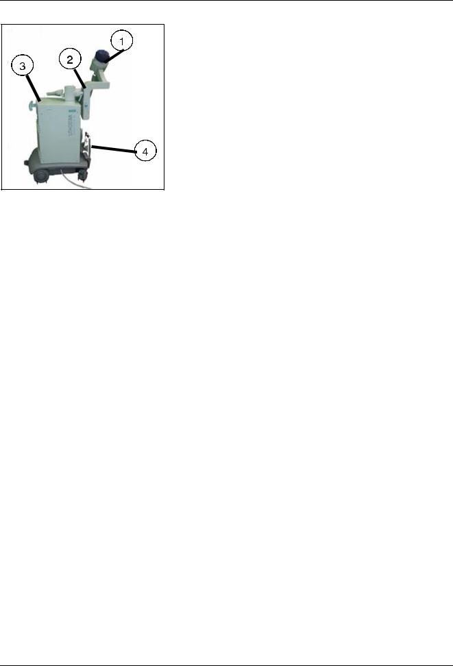
Product-specific Information
This document is valid for the established Lithostar Modularis and the new "low end lithotripter" called the Modularis Vario. Overview of difference between the two units:
Modularis
•(1) Shock wave head C with 120 mm focus depth.
•(2) Length of therapy arm incl. shock head = 1800 mm.
•(3) Energy charging unit with spark gap technology.
•(4) Docking technology implemented with docking plate.
Modularis Vario
•(1) Shock wave head C plus with a focus depth of 140 mm (*1) including an adapted isocenter phantom.
•(2) Length of therapy arm incl. shock head = 900 mm.
•(3) Energy charging unit with fast high voltage switch (*2).
•(4) Docking technology implemented with docking mandrel.
Fig. 1: Modularis
Siemens AG |
SPL1-130.840.01.05.02 |
Page 11 of 138 |
LITHOSTAR MODULARIS |
Medical Solutions |
04.05 |
CS PS 24 |
|
12 |
General |
Fig. 2: |
Modularis Vario |
*1 The shock wave head Cplus with a 140-mm focal depth is upgradable for the normal |
|
Modularis unit. In this case, it is not different in every way. All new Modularis units will be shipped with shock wave head C plus (July 2003, except USA ).
*2 The spark gap will no longer be used in the Multiline and Modularis Lithotripters. Beginning July 2003, all charging units will be equipped with the "Fast High Voltage Switch". This switch is not a consumable and not a spare part. Thus the only spare part is the charging unit.
NOTE |
|
By observing the above mentioned differences, all known techni- |
|
|
cal information is usable for the established Modularis and the |
|
||
|
|
Modularis Vario. |
|
|
|
LITHOSTAR MODULARIS |
SPL1-130.840.01.05.02 |
Page 12 of 138 |
Siemens AG |
|
04.05 |
CS PS 24 |
Medical Solutions |

LITHOSTAR MODULARIS Error List |
13 |
|||
|
|
|
|
|
|
NOTE |
Error messages from the SIREMOBIL Iso-C have not been listed. |
||
|
|
(Refer to the SIREMOBIL Iso-C service documents |
|
|
|
|
|
||
|
|
|
|
|
Siemens AG |
SPL1-130.840.01.05.02 |
Page 13 of 138 |
LITHOSTAR MODULARIS |
Medical Solutions |
04.05 |
CS PS 24 |
|

14 |
|
|
LITHOSTAR MODULARIS Error List |
Info, E00 and E99 |
|
||
|
|
|
|
|
E00 |
Error Text: |
System was switched on. |
|
|
|
|
|
|
Possible |
|
|
|
cause/action: |
|
|
|
|
|
|
E99 |
Error Text: |
The system was switched off without deleting the therapy data. |
|
|
|
|
|
|
Possible |
Press the Reset button. |
|
|
cause/action: |
|
|
|
|
|
LITHOSTAR MODULARIS |
SPL1-130.840.01.05.02 |
Page 14 of 138 |
Siemens AG |
|
04.05 |
CS PS 24 |
Medical Solutions |

LITHOSTAR MODULARIS Error List |
15 |
Water System, E10-E12
LITHOSTAR MODULARIS circuit diagram J1048, pages 13 and 14.
E10 |
Error Text: |
Cooling system losing water. |
|
|
|
|
Possible |
Is water running out of the hoses? |
|
cause/action: |
Pmin switch o.k.? |
|
|
|
|
|
D3.X3 board connection o.k.? |
|
|
Fill the cooling system. |
|
|
|
E11 |
Error Text: |
Maximum pressure in the cooling system exceeded. |
|
|
Pressure switch Pmax responded. |
|
|
|
|
Possible |
Are the hoses blocked, kinked? |
|
cause/action: |
Pmax switch o.k.? |
|
|
|
|
|
D3.X3 board connection o.k? |
|
|
Is the cooling unit operating? |
|
|
Check the fill level in the cooling system. |
|
|
|
E12 |
Error Text: |
Minimum pressure in the cooling system exceeded. |
|
|
Pressure switch Pmin responded. |
|
|
|
|
Possible |
Is water running out of the hoses and hose connections? |
|
cause/action: |
Air in the cooling system? |
|
|
|
|
|
Check the fill level in the cooling system. |
|
|
|
Siemens AG |
SPL1-130.840.01.05.02 |
Page 15 of 138 |
LITHOSTAR MODULARIS |
Medical Solutions |
04.05 |
CS PS 24 |
|

16 |
|
|
LITHOSTAR MODULARIS Error List |
Water System, E14-E15 |
|
||
|
|
|
|
|
E14 |
Error Text: |
Water level too low in the water reservoir tank. |
|
|
|
|
|
|
Possible |
Not enough water in the tank. |
|
|
cause/action: |
Float switch in the tank o.k.? |
|
|
|
|
|
|
|
D3.X3 board connection o.k.? |
|
|
|
Completely fill the coupling bellows, deselect automatic pres- |
|
|
|
sure regulation, and drain the water. |
|
|
|
Repair any leaks. |
|
|
|
Refill the water in the reservoir tank. |
|
|
|
|
|
E15 |
Error Text: |
Coupling pressure not o.k. |
|
|
|
|
|
|
Possible |
Pressure sensor on the shock head o.k.? |
|
|
cause/action: |
If water can still be pumped out, the sensor is probably defec- |
|
|
|
|
|
|
|
tive (refer to "Working with the Terminal Program: Show Diag- |
|
|
|
nostic Data"). |
|
|
|
Suction hose correctly inserted in the coupling bellows? |
|
|
|
Return hose kinked? |
|
|
|
D3.X8 board connection o.k.? |
|
|
|
Fill the coupling system. |
|
|
|
If the error occurs only with obese patients, the suction hose in |
|
|
|
the coupling bellows may be kinked. |
|
|
|
|
LITHOSTAR MODULARIS |
SPL1-130.840.01.05.02 |
Page 16 of 138 |
Siemens AG |
|
04.05 |
CS PS 24 |
Medical Solutions |

LITHOSTAR MODULARIS Error List |
17 |
Controls, E20-E21
If the control panel is dark: check fuse F5 on the D3 board.
E20 |
Error Text: |
No contact with the control unit (this error is visible only when |
|
|
reading out the error log with the service PC). |
|
|
|
|
Possible |
X5 connection cable correctly connected to the control unit? |
|
cause/action: |
Check the F5 fuse on the D3 board. |
|
|
|
|
|
If the error occurs after replacing the D3 board: is X35 connec- |
|
|
tor properly connected? |
|
|
|
E21 |
Error Text: |
X-ray button on the control unit activated with switch-on. |
|
|
|
|
Possible |
X-ray button stuck? |
|
cause/action: |
Control unit o.k.? |
|
|
|
|
|
Cable o.k.? |
|
|
|
Siemens AG |
SPL1-130.840.01.05.02 |
Page 17 of 138 |
LITHOSTAR MODULARIS |
Medical Solutions |
04.05 |
CS PS 24 |
|

18 |
|
|
LITHOSTAR MODULARIS Error List |
Controls, E22-E25 |
|
||
|
|
|
|
|
E22 |
Error Text: |
QRS signal from ECG unit missing, i.e. no ECG triggering pos- |
|
|
|
sible. |
|
|
|
|
|
|
Possible |
Trigger cable connected to ECG unit? |
|
|
cause/action: |
ECG triggering selected on the control unit? Trigger cable |
|
|
|
|
|
|
|
plugged in on D3.X70? |
|
|
|
|
|
E23 |
Error Text: |
Motor for C-Arm movement in LITHOSTAR MODULARIS |
|
|
|
drawing too much current. |
|
|
|
|
|
|
Possible |
C-Arm moving freely? |
|
|
cause/action: |
SIREMOBIL Iso-C cable connected? |
|
|
|
|
|
|
|
Brake in SIREMOBIL Iso-C can be released, i.e. is the motor |
|
|
|
not locked? |
|
|
|
Brake connection cable in SM Iso-C o.k.? (D3.X38 - SM Iso-C) |
|
|
|
Motor connection cable o.k. (board D3.X36)? |
|
|
|
D3 board? |
|
|
|
Motor connection cable o.k. (D3.X36 board)? |
|
|
|
Settings for the SIREMOBIL Iso brakes o.k.? (Angulation and |
|
|
|
orbital in 0°. LITHOSTAR MODULARIS not coupled. Attach a |
|
|
|
spring balance at the handle near the I.I. Release the angula- |
|
|
|
tion brake and pull with the spring balance. The C-Arm must |
|
|
|
move when the spring balance indicates a value from 20N-30N |
|
|
|
- preferably close to 20 N. Settings are made at the position |
|
|
|
where the angulation motor is coupled. Wrench size 30 mm, |
|
|
|
coupling must be removed). Also refer to SPR2-230.061.01... |
|
|
|
chapter 7. |
|
|
|
D3 board? |
|
|
|
|
|
E24 |
Error Text: |
C-Arm blocked. |
|
|
|
No change on the actual value potentiometer in LITHOSTAR |
|
|
|
MODULARIS. |
|
|
|
|
|
|
Possible |
C-Arm moving freely? |
|
|
cause/action: |
Potentiometer o.k.? |
|
|
|
|
|
|
|
Correct tension on the belt? |
|
|
|
Connection cable to potentiometer o.k.? (D3.X38) |
|
|
|
Check the setting of the SIREMOBIL angulation brake (see |
|
|
|
E23) |
|
|
|
|
|
E25 |
Error Text: |
C-Arm potentiometer not working. |
|
|
|
|
|
|
Possible |
Potentiometer connected? |
|
|
cause/action: |
Check the D3.X30 connector! |
|
|
|
|
|
|
|
Connect the cable to the potentiometer. |
|
|
|
|
LITHOSTAR MODULARIS |
SPL1-130.840.01.05.02 |
Page 18 of 138 |
Siemens AG |
|
04.05 |
CS PS 24 |
Medical Solutions |

LITHOSTAR MODULARIS Error List |
19 |
|||
Controls, E26-E29 |
|
|
||
|
|
|
|
|
|
E26 |
Error Text: |
ECG option not installed. |
|
|
|
|
|
|
|
|
Possible |
Warning message only. |
|
|
|
cause/action: |
|
|
|
|
|
|
|
|
E27 |
Error Text: |
Control unit. |
|
|
|
|
|
|
|
|
Possible |
Key sticking. |
|
|
|
cause/action: |
Replace control panel. |
|
|
|
|
|
|
|
|
|
|
|
|
E28 |
Error Text: |
C-Arm pivots in the wrong direction. |
|
|
|
|
|
|
|
|
Possible |
Cables connected incorrectly to the potentiometer or the |
|
|
|
cause/action: |
motor? |
|
|
|
|
Correct tension on the belt? |
|
|
|
|
Check the setting of the SIREMOBIL angulation brake (see |
|
|
|
|
E23). |
|
|
|
|
|
|
|
E29 |
Error Text: |
Shock wave release button sticking. |
|
|
|
|
|
|
|
|
Possible |
Check control unit. Circuit diagram J1048 - 25. |
|
|
|
cause/action: |
|
|
|
|
|
|
|
Siemens AG |
SPL1-130.840.01.05.02 |
Page 19 of 138 |
LITHOSTAR MODULARIS |
Medical Solutions |
04.05 |
CS PS 24 |
|

20 |
|
|
LITHOSTAR MODULARIS Error List |
Monitoring, E31-E34 |
|
||
|
|
|
|
|
E31 |
Error Text: |
Temperature sensor supplying incorrect data. |
|
|
|
|
|
|
Possible |
Temperature sensor o.k.? |
|
|
cause/action: |
D3.X2 connection cable o.k.? |
|
|
|
|
|
|
|
The temperature difference can be read out on the service PC. |
|
|
|
|
|
E32 |
Error Text: |
The temperature at the shock wave head has exceeded the |
|
|
|
maximum value. |
|
|
|
|
|
|
Possible |
Let the shock wave head cool down, but do not switch the sys- |
|
|
cause/action: |
tem off! |
|
|
|
Check to ensure that the cooling unit is operating. |
|
|
|
If the M1 cooling pump is running, the pump head may need to |
|
|
|
be replaced. |
|
|
|
If the error reoccurs, check the function of the cooling unit. |
|
|
|
|
|
E34 |
Error Text: |
Temperature cannot be determined: could not access the ADC |
|
|
|
when converting the analog values from the temperature sen- |
|
|
|
sor. |
|
|
|
Voltage supply for the temperature sensors outside acceptable |
|
|
|
range. |
|
|
|
|
|
|
Possible |
D3.X2 connection cable o.k.? |
|
|
cause/action: |
D3 board? |
|
|
|
|
|
|
|
Read out the temperature with the service PC. |
|
|
|
Refer also to error 45. |
|
|
|
|
LITHOSTAR MODULARIS |
SPL1-130.840.01.05.02 |
Page 20 of 138 |
Siemens AG |
|
04.05 |
CS PS 24 |
Medical Solutions |
LITHOSTAR MODULARIS Error List |
21 |
|||
Monitoring, E40-E48 |
|
|
||
|
|
|
|
|
|
E40 |
Error Text: |
Cooling pump fuse defective. |
|
|
|
|
|
|
|
|
Possible |
F2 fuse on D3 board o.k.? |
|
|
|
cause/action: |
|
|
|
|
|
|
|
|
E41 |
Error Text: |
M1 cooling pump defective. |
|
|
|
|
|
|
|
|
Possible |
M1 motor o.k.? Circuit diagram J1048 - 13 |
|
|
|
cause/action: |
D3.X7 connection cable o.k.? |
|
|
|
|
|
|
|
|
|
|
|
|
E42 |
Error Text: |
Coupling pump defective. |
|
|
|
|
|
|
|
|
Possible |
M2 motor o.k.? Circuit diagram J1048 - 13 |
|
|
|
cause/action: |
D3.X7 connection cable o.k.? |
|
|
|
|
|
|
|
|
|
|
|
|
E43 |
Error Text: |
Fuse for coupling pump defective. |
|
|
|
|
|
|
|
|
Possible |
F3 fuse on D3 board o.k.? |
|
|
|
cause/action: |
|
|
|
|
|
|
|
|
E44 |
Error Text: |
5 volt power supply defective. |
|
|
|
|
|
|
|
|
Possible |
Replace D3 board. |
|
|
|
cause/action: |
|
|
|
|
|
|
|
|
E45 |
Error Text: |
18 volt power supply defective. |
|
|
|
|
|
|
|
|
Possible |
LED VCC18 on D3 board o.k.? Circuit diagram J1048 - 11 |
|
|
|
cause/action: |
D3.X8 connection cable o.k.? |
|
|
|
|
|
|
|
|
|
Check the power supply for the pressure sensors! |
|
|
|
|
|
|
|
E46 |
Error Text: |
17 volt power supply defective |
|
|
|
|
|
|
|
|
Possible |
LED VCC17 on D3 board o.k.? |
|
|
|
cause/action: |
Replace D3 board. |
|
|
|
|
|
|
|
|
|
|
|
|
E47 |
Error Text: |
Valve and card terminal fuse defective? |
|
|
|
|
|
|
|
|
Possible |
Short circuit? |
|
|
|
cause/action: |
F4 fuse on D3 board? Circuit diagram J1048 - 13 |
|
|
|
|
|
|
|
|
|
Check valve (coupling circuit). |
|
|
|
|
Check card terminal. |
|
|
|
|
|
|
|
E48 |
Error Text: |
Reference for temperature sensors defective. |
|
|
|
|
|
|
|
|
Possible |
Replace temperature sensors. |
|
|
|
cause/action: |
Replace D3 board. |
|
|
|
|
|
|
|
|
|
|
|
Siemens AG |
SPL1-130.840.01.05.02 |
Page 21 of 138 |
LITHOSTAR MODULARIS |
Medical Solutions |
04.05 |
CS PS 24 |
|

22 |
|
|
LITHOSTAR MODULARIS Error List |
Monitoring, E49-E54 |
|
||
|
|
|
|
|
E49 |
Error Text: |
Reference potentiometer defective. |
|
|
|
|
|
|
Possible |
Short circuit in potentiometer for C-arm movement or potenti- |
|
|
cause/action: |
ometer for ultrasound probe (only if option is available)? |
|
|
|
D3.X38, D3.X28 connection cable (ultrasound option) o.k.? |
|
|
|
Circuit diagram J1048 - 16/17. |
|
|
|
Use the service PC to read the current potentiometer (menu |
|
|
|
"d"). |
|
|
|
For troubleshooting when the ultrasound option is available: |
|
|
|
Remove the board for the ultrasound option and cables X28 |
|
|
|
and X29 from the D3 board. |
|
|
|
|
|
E50 |
Error Text: |
-5 volt power supply defective. |
|
|
|
|
|
|
Possible |
Replace D3 board. |
|
|
cause/action: |
|
|
|
|
|
|
E52 |
Error Text: |
Battery voltage for battery-buffered RAM and real-time clock |
|
|
|
too low. |
|
|
|
|
|
|
Possible |
Replace the lithium battery on the D3 board. |
|
|
cause/action: |
|
|
|
|
|
|
E53 |
Error Text: |
Incorrect data in the battery-buffered RAM. |
|
|
|
|
|
|
Possible |
Normal occurrence during initial startup or after replacing the |
|
|
cause/action: |
lithium battery. |
|
|
|
Check the lithium battery! |
|
|
|
Replace the D3 board. |
|
|
|
Perform a software download! |
|
|
|
|
|
E54 |
Error Text: |
Clock stopped (this message is also displayed when the bat- |
|
|
|
tery is replaced) |
|
|
|
|
|
|
Possible |
D3.X31 - XP7 connection cable present under the cover? |
|
|
cause/action: |
Set the clock! |
|
|
|
|
|
|
|
|
LITHOSTAR MODULARIS |
SPL1-130.840.01.05.02 |
Page 22 of 138 |
Siemens AG |
|
04.05 |
CS PS 24 |
Medical Solutions |

LITHOSTAR MODULARIS Error List |
23 |
High Voltage Circuit, E60 - E67
LITHOSTAR MODULARIS circuit diagram J1048 - 12.
E60 |
Error Text: |
Charging current too low during the charging process. |
|
|
|
|
Possible |
Check the line voltage! |
|
cause/action: |
Replace the charging / energy unit! |
|
|
|
|
|
|
E61 |
Error Text: |
Overvoltage in the charging unit. |
|
|
|
|
Possible |
System OFF |
|
cause/action: |
- 10 minute pause - System ON. |
|
|
|
|
|
Replace the charging / energy unit! |
|
|
|
E62 |
Error Text: |
Overtemperature in the charging unit. |
|
|
|
|
Possible |
Heat in the LITHO MODULARIS? |
|
cause/action: |
System OFF - 10 minute pause - System ON. |
|
|
|
|
|
Replace the charging / energy unit! |
|
|
|
E63 |
Error Text: |
Capacitor defective in the charging / energy unit (out of toler- |
|
|
ance). |
|
|
|
|
Possible |
Replace the charging / energy unit! |
|
cause/action: |
|
|
|
|
E64 |
Error Text: |
Default voltage not attained. |
|
|
Current voltage after frequency converter (Unom) is greater |
|
|
than selected voltage. |
|
|
|
|
Possible |
Check the fiber optic cable! 1) |
|
cause/action: |
Replace the charging / energy unit! |
|
|
|
|
|
|
E65 |
Error Text: |
Charging voltage too high during the charging process. |
|
|
|
|
Possible |
Replace the charging / energy unit! |
|
cause/action: |
|
|
|
|
E66 |
Error Text: |
Default voltage incorrect. |
|
|
|
|
Possible |
Check the fiber optic cable! 1) |
|
cause/action: |
Replace the charging / energy unit! |
|
|
|
|
|
|
E67 |
Error Text: |
No ignition of spark gap after trigger pulse (several times). |
|
|
|
|
Possible |
Check the fiber optic cable! 1) |
|
cause/action: |
Replace the spark gap! |
|
|
|
|
|
|
Siemens AG |
SPL1-130.840.01.05.02 |
Page 23 of 138 |
LITHOSTAR MODULARIS |
Medical Solutions |
04.05 |
CS PS 24 |
|

24 |
|
|
LITHOSTAR MODULARIS Error List |
|
High Voltage Circuit, E68 - E74 |
||||
|
|
|
|
|
|
E68 |
Error Text: |
Charging current too high during charging process. |
|
|
|
|
|
|
|
|
Possible |
Replace the charging / energy unit! |
|
|
|
cause/action: |
|
|
|
|
|
|
|
|
E69 |
Error Text: |
Repeated self-ignition of the spark gap. |
|
|
|
|
|
|
|
|
Possible |
Replace the spark gap! |
|
|
|
cause/action: |
|
|
|
|
|
|
|
|
E70 |
Error Text: |
Charging current too low after ignition! |
|
|
|
|
|
|
|
|
Possible |
Check the high voltage cable connections! |
|
|
|
cause/action: |
Check the high voltage connector! |
|
|
|
|
||
|
|
|
Replace the shock wave head! |
|
|
|
|
|
|
|
E71 |
Error Text: |
Charging current too high after ignition. |
|
|
|
|
|
|
|
|
Possible |
Check the high voltage cable! |
|
|
|
cause/action: |
Check the high voltage connector! |
|
|
|
|
||
|
|
|
Replace the shock wave head! |
|
|
|
|
|
|
|
E72 |
Error Text: |
No communication possible with the charging / energy unit. |
|
|
|
|
|
|
|
|
Possible |
Check the line voltage at the charging / energy unit! |
|
|
|
cause/action: |
Replace the fuse in the charging / energy unit! |
|
|
|
|
||
|
|
|
Check the fiber optic cable! 1) |
|
|
|
|
Replace the charging / energy unit! |
|
|
|
|
|
|
|
E73 |
Error Text: |
Message: Constancy limit reached. |
|
|
|
|
|
|
|
|
Possible |
For user information only. |
|
|
|
cause/action: |
Approx. 10-15 treatments still possible, then error 74 appears. |
|
|
|
|
||
|
|
|
|
|
|
E74 |
Error Text: |
Constancy limit reached. |
|
|
|
|
|
|
|
|
Possible |
The constancy limit has been reached. |
|
|
|
cause/action: |
• Replace the following parts: |
|
|
|
|
- |
shock wave head |
|
|
|
- |
spark gap and |
In addition, replace the water in the entire system!
1) Before replacing the charging / energy unit, check the fiber optic cable (LWL):
•Disconnect the fiber optic cable at both ends and check by holding it up to the light
or
•Place it on the Clk (U5) of the D3 board and check whether light is visible.
LITHOSTAR MODULARIS |
SPL1-130.840.01.05.02 |
Page 24 of 138 |
Siemens AG |
|
04.05 |
CS PS 24 |
Medical Solutions |

LITHOSTAR MODULARIS Error List |
25 |
||||
High Voltage Circuit, E75 - E78 |
|
||||
|
|
|
|
|
|
|
E75 |
|
Error Text: |
Chip card terminal error (documented in error log only). |
|
|
|
|
|
|
|
|
|
|
Possible |
Check revision level for D3 board: Rev. 00 - 02: replace D3 |
|
|
|
|
cause/action: |
board. Rev. 03 and higher: replace chip card reading device. |
|
|
|
|
|
Wrong card or card incorrectly inserted. |
|
|
|
|
|
|
|
|
E76 |
|
Error Text: |
Chip card expired |
|
|
|
|
|
|
|
|
|
|
Possible |
Insert a new card. |
|
|
|
|
cause/action: |
|
|
|
|
|
|
|
|
|
E77 |
|
Error Text: |
Chip card communication error |
|
|
|
|
|
|
|
|
|
|
Possible |
Check revision level for D3 board: Rev. 00 - 02: replace D3 |
|
|
|
|
cause/action: |
board. Rev. 03 and higher: replace chip card reading device |
|
|
|
|
|
Cable? If the error reoccurs after replacing the D3 board, is the |
|
|
|
|
|
X33 connector properly connected? |
|
|
|
|
|
|
|
|
E78 |
|
Error Text: |
Charging process too long. |
|
|
|
|
|
|
|
|
|
|
Possible |
Line voltage o.k.? |
|
|
|
|
cause/action: |
Replace the charging / energy unit! |
|
|
|
|
|
|
|
|
|
|
|
|
|
|
E79 |
|
Error Text: |
Short circuit - call Service |
|
|
|
|
|
|
|
|
|
|
Possible |
High voltage cable or energy unit defect |
|
|
|
|
cause/action: |
Replace the cable or the energy unit! |
|
|
|
|
|
|
|
|
|
|
|
|
|
|
|
|
|
||
1) |
Before replacing the charging / energy unit, check the fiber optic cable (LWL): |
|
|||
•Disconnect the fiber optic cable at both ends and check by holding it up to the light
or
•Place it on the Clk (U5) of the D3 board and check whether light is visible.
Siemens AG |
SPL1-130.840.01.05.02 |
Page 25 of 138 |
LITHOSTAR MODULARIS |
Medical Solutions |
04.05 |
CS PS 24 |
|

26 |
|
|
LITHOSTAR MODULARIS Error List |
Internal Errors, E80-E89 |
|
||
|
|
|
|
|
E80 |
Error Text: |
Flash memory defective. |
|
|
|
|
|
|
Possible |
Not applicable for the user. |
|
|
cause/action: |
Read out the memory and perform a reset at the next opportu- |
|
|
|
|
|
|
|
nity. |
|
|
|
|
|
E81 |
Error Text: |
CMOS pulse counter incorrect. |
|
|
|
|
|
|
Possible |
If this error occurs repeatedly, D3 board must be replaced. |
|
|
cause/action: |
|
|
|
|
|
|
E82 |
Error Text: |
Pulse counter backup incorrect |
|
|
|
|
|
|
Possible |
If this error occurs repeatedly, D3 board must be replaced. |
|
|
cause/action: |
|
|
|
|
|
|
E83 |
Error Text: |
CMOS chip card data incorrect |
|
|
|
|
|
|
Possible |
|
|
|
cause/action: |
|
|
|
|
|
|
E85 |
Error Text: |
Measurement acquisition incorrect. |
|
|
|
|
|
|
Possible |
|
|
|
cause/action: |
|
|
|
|
|
|
E86 |
Error Text: |
Flash memory defective |
|
|
|
|
|
|
Possible |
Not applicable for the user. |
|
|
cause/action: |
Read out the memory and perform a reset at the next opportu- |
|
|
|
|
|
|
|
nity. |
|
|
|
|
|
E89 |
Error Text: |
Watchdog responded. |
|
|
|
|
|
|
Possible |
If this error occurs repeatedly, D3 board must be replaced. |
|
|
cause/action: |
Appears each time a reset is performed with the S3 switch on |
|
|
|
|
|
|
|
D3 board. |
|
|
|
This error may occur if the system is switched off during initial- |
|
|
|
ization. |
|
|
|
|
LITHOSTAR MODULARIS |
SPL1-130.840.01.05.02 |
Page 26 of 138 |
Siemens AG |
|
04.05 |
CS PS 24 |
Medical Solutions |

LITHOSTAR MODULARIS Error List |
27 |
Ultrasound, E90-E93
E90 |
Error Text: |
|
|
Possible |
No connection from LITHOSTAR to SONOLINE |
|
cause/action: |
|
|
|
|
E91 |
Error Text: |
Potentiometer skips. |
|
Possible |
Cable from potentiometer to D3 board ok? Potentiometer |
|
cause/action: |
defect? |
|
|
Fig. 3: |
|
|
|
E92 |
Error Text: |
The two potentiometers have different values. |
|
|
|
|
Possible |
Dampness on the potentiometer. |
|
cause/action: |
|
|
|
|
E93 |
Error Text: |
Erroneous US values. |
|
|
|
|
Possible |
C-MOS has lost values. Adjust the potentiometer (point "U" in |
|
cause/action: |
the service menu). |
|
|
Check the default values (see SPL1-130.038.01...). |
Siemens AG |
SPL1-130.840.01.05.02 |
Page 27 of 138 |
LITHOSTAR MODULARIS |
Medical Solutions |
04.05 |
CS PS 24 |
|

28 |
LITHOSTAR MODULARIS Error List |
Displays on the D3 Board
Once the system is turned on, different symbols are displayed chronologically on the D3 board display .
Display |
Possible cause/action |
|
|
|
|
0 |
System o.k. (only with the ultrasound localization option and if a communica- |
|
tion was set up to the ultrasound device.) |
|
|
d |
Software download. |
|
|
1 |
Data transfer, the decimal point is blinking. |
|
|
4 |
The receiving file is being checked. |
|
|
5 |
Software download time too long. |
|
|
7 |
Everything o.k. (only if no ultrasound localization option is available or if the |
|
ultrasound device is turned off.) |
|
|
- |
The service switch is set to normal mode - only for boards that still have no |
|
software. |
|
|
LITHOSTAR MODULARIS |
SPL1-130.840.01.05.02 |
Page 28 of 138 |
Siemens AG |
|
04.05 |
CS PS 24 |
Medical Solutions |

LITHOSTAR MODULARIS Error List |
29 |
Text on the Console
"Chip card invalid"
•This message is displayed when:
-the gold card is still logged on a different LITHOSTAR MODULARIS
-D3 board was replaced and the "init counter" on the gold card is already set to 3.
-the card is defective.
In the normal mode, check whether the LED 174 on the D3 board blinks temporarily and then remains lit when turning it on.
LITHOSTAR MODULARIS SIEMENS
This message is displayed when too many errors occur. In this case, use the service PC to generate an error log.
Siemens AG |
SPL1-130.840.01.05.02 |
Page 29 of 138 |
LITHOSTAR MODULARIS |
Medical Solutions |
04.05 |
CS PS 24 |
|

30 |
LITHOSTAR MODULARIS Error List |
Missing Isocenter Cross on the Ultrasound System
There is no communication between the ultrasound system and the LITHOSTAR MODULARIS.
LITHOSTAR MODULARIS |
SPL1-130.840.01.05.02 |
Page 30 of 138 |
Siemens AG |
|
04.05 |
CS PS 24 |
Medical Solutions |
Loading...