


Gebrauchsund Montageanleitung
Operating and installation instructions
Mode d’emploi et notice de montage
Gebruiksaanwijzing en montagevoorschrift
Downloaded |
|
|
|
from |
|
|
|
Istruzioni d’uso |
www |
|
|
|
|||
|
. |
|
|
|
|
||
y de montaje |
|
vandenborreen |
|
e per il montaggio |
|
|
de |
Instrucciones de uso |
|
|
|
|
|
|
|
|
|
|
|
|
|
|
. |
Instruções de serviçio |
|
be |
|
|
|
||
|
|
||
e de montagem
fr
nl
it
es
pt
de |
Seite |
03 – 15 |
en |
page |
16 – 28 |
fr |
page |
29 – 41 |
nl |
pagina |
42 – 54 |
Abb. 1
GAS
GAZ
KAASU
GASS
MIND. 650
Downloadedes |
página |
68 – 80 |
|
it |
|
pagina |
55 – 67 |
pt |
frompágina |
81 – 93 |
|
|
|
www |
|
|
|
|
. |
|
|
|
vandenborre |
|
|
|
. |
|
|
|
be |
Abb. 1
ELEKTRO
ELECTR.
ELETT.
EL.
MIN. 430 |
2
Gebrauchsanleitung
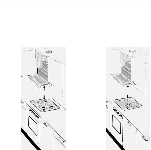
Gerätebeschreibung
Oberschrank |
Filterauszug |
Schalter |
Beleuchtung |
Schalter |
Lüfterstufen |
Betriebsarten
Abluftbetrieb:
Der Lüfter der Dunstabzugshaube saugt den Küchendunst an und
leitet ihn durch den Fettfilter ins Freie.
Der Fettfilter nimmt die fettigen Bestandteile des Küchendunstes auf.
Die Küche bleibt weitgehend frei von Fett und Geruch.
DBei Abluftbetrieb der Dunstabzugshaube und gleichzeitigem Betrieb schornsteinabhängiger Feuerungen (wie z. B. Gas-, Öloder Kohleheizgeräte, Durchlauferhitzer, Warmwasserbereiter) muss für ausreichend Zuluft gesorgt werden, die von der Feuerstätte zur Verbrennung benötigt wird.
Ein gefahrloser Betrieb ist möglich, wenn der Unterdruck im Aufstellraum der Feuerstätte von 4 Pa (0,04 mbar) nicht überschritten wird.
3

|
|
|
Downloaded |
|
|
|
|
Wichtige Hinweise: |
|
|
|
|
|
Vor dem ersten Benutzen |
|
|
|
|
|
Diese Gebrauchsanleitung gilt für |
from |
|
|
|
|
Bevor Sie das neue Gerät benutzen, |
|||
|
|
mehrere Geräte-Ausführungen. |
lesen Sie bitte sorgfältig die |
|
|
|
|
Es ist möglich, dass einzelne |
Gebrauchsanleitung. |
|
|
|
|
Ausstattungsmerkmale beschrieben |
Sie enthält wichtige Informationen für Ihre |
||
|
|
sind, die nicht auf Ihr Gerät zutreffen. |
Sicherheit sowie zum wwwGebrauch und zur |
||
|
|||||
|
|
|
Pflege des Gerätes. |
. |
|
|
|
Durch unsachgemäße Reparaturen |
vandenborre |
||
|
|
Diese Dunstabzugshaube entspricht den |
Bewahren Sie die Gebrauchsund |
||
|
|
einschlägigen Sicherheitsbestimmungen. |
|||
|
|
Reparaturen dürfen nur von Fachkräften |
Montageanleitung ggf. für einen |
||
|
|
Nachbesitzer gut auf. |
|
|
|
|
|
durchgeführt werden. |
|
|
|
|
|
|
|
|
|
|
|
können erhebliche Gefahren für den |
|
. |
|
|
|
|
|
be |
|
|
|
Benutzer entstehen. |
|
|
|
|
|
|
|
|
|
|
|
Ist das Gerät beschädigt, dürfen Sie es |
Unter der Dunstabzugshaube nicht |
||
|
|
nicht in Betrieb nehmen. |
flambieren. |
|
|
|
|
Anschluss und Inbetriebnahme dürfen |
Brandgefahr am Fettfilter durch |
||
|
|
! aufsteigende Flammen. |
|
|
|
|
|
nur von einem Fachmann durchgeführt |
Über einer Feuerstätte für feste |
||
|
|
werden. |
|||
|
|
Wenn die Anschlussleitung dieses |
Brennstoffe (Kohle, Holz und dgl.) ist der |
||
|
|
Betrieb der Dunstabzugshaube nur bedingt |
|||
|
|
Gerätes beschädigt wird, muss sie durch |
|||
|
|
gestattet (siehe Montageanleitung). |
|||
|
|
den Hersteller oder seinen Kundendienst |
|||
|
|
|
|
|
|
|
|
oder eine ähnlich qualifizierte Person ersetzt |
|
|
|
|
|
werden, um Gefährdung zu |
Gas-Kochmulden / Gas-Herde |
||
|
|
vermeiden. |
|||
|
|
Gas-Kochstellen immer sachgemäß |
|||
|
|
Verpackungsmaterial ordnungsgemäß |
|||
|
|
benutzen. |
|
|
|
|
|
entsorgen (siehe Montageanleitung). |
|
|
|
|
|
Wichtig: |
|
|
|
|
|
Dunstabzugshaube nur mit |
|
|
|
|
|
Die Flammen der Gas-Kochstellen müssen |
|||
|
|
eingesetzten Lampen betreiben. |
immer mit Kochgeschirr abgedeckt sein. |
||
|
|
Defekte Lampen sollten sofort ersetzt |
Durch die starke Hitzeentwicklung |
||
|
|
der offenen Gasflammen könnte die |
|||
|
|
werden, um Überlastung der restlichen |
! Dunstabzugshaube beschädigt werden. |
||
Lampen zu vermeiden.
Dunstabzugshaube nie ohne Fettfilter betreiben.
Überhitzte Fette oder Öle können sich leicht entzünden.
Darum Speisen mit Fetten oder Ölen, z. B. Pommes frites, nur unter Aufsicht zubereiten.
4

Bedienen der Dunstabzugshaube
Der Küchendunst wird am wirkungsvollsten beseitigt durch:
Einschalten des Lüfters bei Kochbeginn.
Ausschalten des Lüfters
erst einige Minuten nach Kochende.
Einschalten des Lüfters:
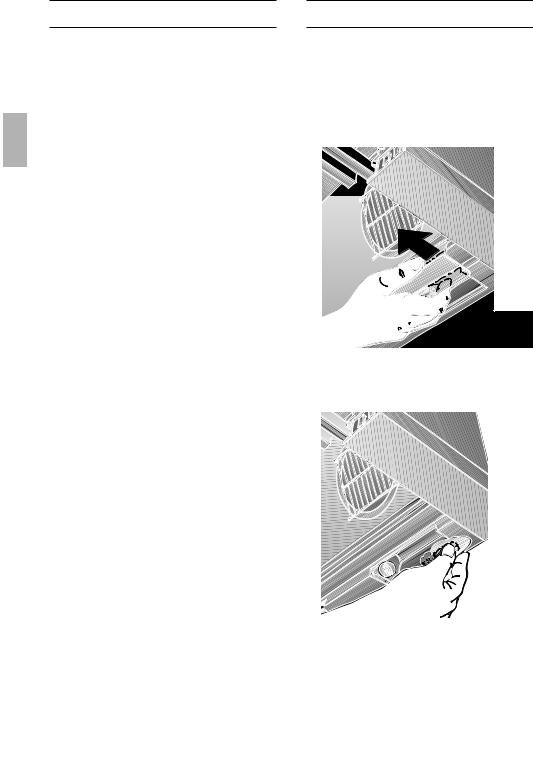
1.Filterauszug an der Griffleiste ausziehen.Der Lüfter ist in Betrieb.
2.Gewünschte Lüftereinstellung wählen.
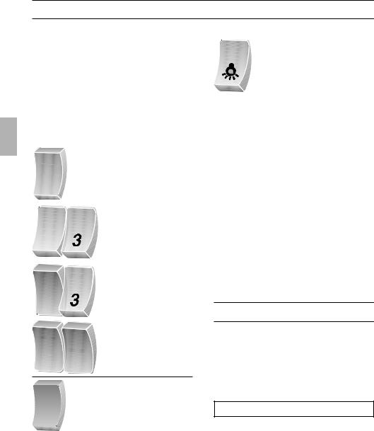
Bedienelemente der verschiedenen Modelle:
3 |
Stufe 3 |
1 |
Stufe 1 |
2 |
Stufe 2 |
|
|
2 |
Stufe 1 |
|
Beleuchtung:Downloaded |
|
|
0 |
from |
|
Aus |
|
|
|
www |
|
|
Ein |
|
|
|
. |
|
|
vandenborre |
Hinweis: Die Beleuchtung kann zu jeder |
||
Zeit verwendet werden, auch wenn der |
||
Filterauszug eingeschoben ist. |
|
|
|
|
. |
|
|
be |
|
Stufe 2 |
2 |
|
|
Stufe 3 |
2 |
3 |
|
|
1 |
Stufe 1 |
|
|
0 |
Aus |
2 |
Stufe 2 |
Ausschalten des Lüfters:
Filterauszug bis Anschlag einschieben.
Hinweis: Beim erneuten Ausziehen des Filterauszuges arbeitet der Lüfter in der zuletzt gewählten Einstellung.
Störungen
Bei eventuellen Rückfragen oder Störungen, Kundendienst anrufen.
(Siehe Kundendienststellenverzeichnis).
Bei Anruf bitte angeben:
E-NR. FD
Tragen Sie die Nummern in obige Felder ein. Die Nummern sind auf dem Typenschild, nach Abnahme der Fettfilter, im Innenraum der Dunstabzugshaube zu finden.
5
|
|
|
AusDownloaded- und Einbauen der Metall- |
|
|||||
|
|
Fettfilter: |
|
||||||
|
|
Filter und Wartung |
|
|
|
|
|
|
|
|
|
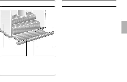
Zur Aufnahme der fettigen Bestandteile |
Filterrahmen |
from |
|||||
|
|
|
|
|
|||||
|
|
des Küchendunstes sind Metall- |
Ausbauen: |
||||||
|
|
Fettfilter eingesetzt. |
1. |
|
|
|
www |
||
|
|
Die Filtermatten bestehen aus unbrenn- |
Filterauszug bis zum Anschlag |
||||||
|
|
|
ausziehen. |
. |
|
||||
|
|
barem Metall. |
2. |
|
|
|
|||
|
|
Achtung: |
Raste an den Filterrahmen in Pfeil- |
||||||
|
|
|
richtung bis zum Anschlag betätigen. |
||||||
|
|
Bei zunehmender Sättigung mit fetthaltigen |
|
|
|
|
|
vandenborre |
|
|
|
Rückständen erhöht sich die |
|
|
|
|
|
||
|
|
|
|
|
|
||||
|
|
Entflammbarkeit und die Funktion der |
|
|
|
|
|
||
|
|
Dunstabzugshaube kann beeinträchtigt |
|
|
|
|
|
||
|
|
|
|
|
|
. |
|||
|
|
werden. |
|
|
|
|
|
|
be |
|
|
Wichtig: |
|
|
|
|
|
|
|
|
|
|
|
|
|
|
|
|
|
|
|
|
|
|
|
|
|
|
|
Durch rechtzeitiges Reinigen der Metall-Fettfilter wird der Brandgefahr vorgebeugt, die durch Hitzestau beim Frittieren oder Braten entstehen kann.
Reinigen der Metall-Fettfilter:
Bei normalem Betrieb (täglich 1 bis 2 Stunden) müssen die Metall-Fettfilter nach 8 bis 10 Wochen gereinigt werden.
Das Reinigen kann in der Geschirrspülmaschine erfolgen.
Dabei ist eine leichte Verfärbung möglich.
Wichtig:
Stark gesättigte Metall-Fettfilter nicht zusammen mit Geschirr reinigen.
Beim Reinigen von Hand, Filtermatten in heißer Spüllauge mehrere Stunden einweichen.
Danach abbürsten, gut ausspülen und abtropfen lassen.
Nur Originalfilter verwenden.
Dadurch wird eine optimale Funktion gewährleistet.
Bei zwei Fettfiltern zuerst den vorderen ausbauen.
3.Filterrahmen seitlich abklappen und abnehmen.
Einbauen:
1.Filterauszug bis zum Anschlag ausziehen.
2.Filterrahmen schräg an einer Seite in die Halterung einsetzen, hochklappen und durch Betätigen der Raste bis zum Anschlag einhängen.
Bei zwei Fettfiltern zuerst den hinteren, dann den vorderen Filterrahmen mit dem Profil, in den Filterauszug einbauen.
Auf sicheren Sitz der Fettfilter auf beiden Seiten achten.
6

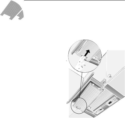
Aktivkohlefilter: |
Ausbauen:Downloaded |
|
Filter und Wartung |
|
|
Zum Binden der Geruchsstoffe beim |
Der Ausbau des Aktivkohlefilters erfolgt in |
|
Umluftbetrieb. |
umgekehrter Reihenfolge. |
|
from |
|
|
Der Aktivkohlefilter wird oberhalb der |
Dazu die Rasthaken nach aussen drücken. |
|
Wechsel des Aktivkohlefilters:www |
|
|
Fettfilter in die Dunstabzugshaube |
|
|
eingebaut. |
. |
|
Dunstabzugshaube einsetzen und mit je |
vandenborre |
|
1. Fettfilter ausbauen (siehe Filter und |
Bei normalem Betrieb (täglich 1 bis 2 |
|
Wartung). |
Stunden) muss der Aktivkohlefilter ungefähr |
|
2. Die zwei beiliegenden Kunststoff-Halter |
1 x im Jahr ausgetauscht werden. |
|
Der Aktivkohlefilter ist im FACHHANDEL |
|
|
rechts und links in das Gehäuse der |
erhältlich (siehe Sonderzubehör). |
|
|
Nur Originalfilter verwenden. |
. |
einer Schraube anschrauben (nur beim |
Dadurch wird die optimale Funktion |
be |
|
||
ersten Einbau eines Aktivkohlefilters |
|
|
gewährleistet. |
|
|
erforderlich). |
|
|
|
|
|
|
Entsorgung des alten Aktivkohlefilters: |
|
|
Aktivkohlefilter enthalten keine |
|
|
Schadstoffe. Sie können z. B. als |
|
|
Restmüll entsorgt werden. |
|
Reinigen und Pflegen
3.Aktivkohlefilter von unten in das Gehäuse der Dunstabzugshaube einschieben und auf beiden Seiten verrasten.
Dabei muss der Rand am Aktivkohlefilter unten sein.
4.Fettfilter wieder einbauen (siehe Filter und Wartung).
 1.
1.


 2.
2.


 3.
3.
Bei Geräten mit Glasplatte im Wrasenauszug:
Die Glasplatte ist abnehmbar und kann in der Geschirrspülmaschine gereingt werden.
Zum Abnehmen die Laschen nach aussen schieben.
7
Reinigen und Pflegen
Dunstabzugshaube durch Ziehen des Netzsteckers bzw. Ausschalten der Sicherung stromlos machen.
Beim Reinigen der Fettfilter die zugänglichen Gehäuseteile von abgelagertem Fett reinigen.
Dadurch wird der Brandgefahr vorgebeugt und die optimale Funktion bleibt erhalten.
Zum Reinigen der Dunstabzugshaube heiße Spüllauge oder mildes Fensterputzmittel verwenden.
Kratzen Sie angetrocknete Verschmutzung nicht ab, sondern weichen Sie diese mit einem feuchten Tuch auf.
Keine scheuernden Mittel oder kratzende Schwämme verwenden.
Hinweis: Alkohol (Spiritus) nicht auf Kunststoffflächen anwenden, es könnten matte Stellen entstehen.
Vorsicht! Küche ausreichend belüften, keine offene Flamme.
Die Bedientasten nur mit milder Spüllauge und einem weichen, feuchten Tuch reinigen.
Keinen Edelstahlreiniger für die Bedientasten verwenden.
Edelstahloberflächen:
Verwenden Sie einen milden nicht scheuernden Edelstahlreiniger.
Reinigen Sie nur in Schliffrichtung.
Edelstahloberflächen nicht mit kratzenden Schwämmen und nicht mit sand-, soda-, säureoder chloridhaltigen Putzmitteln reinigen!
Aluminium-, Lackund Kunststoffoberflächen:
Verwenden Sie ein weiches, fusselfreies Fensteroder Microfasertuch.
Keine trockenen Tücher verwenden.
Verwenden Sie ein mildes Fensterreinigungsmittel.
Keine aggressiven, säureoder laugenhaltigen Reiniger verwenden.
Keine Scheuermittel verwenden.
Auswechseln der Lampen |
||||||
1. |
DownloadedDunstabzugshaube ausschalten und |
|||||
|
|
durch Ziehen des Netzsteckers oder |
||||
|
|
|
|
|
from |
|
|
|
Ausschalten der Sicherung stromlos |
||||
|
|
machen. |
www |
|||
2. |
|
hen. |
||||
|
Filterauszug bis zum Anschlag auszie- |
|||||
3. |
|
|
|
|
. |
|
|
Lampenabdeckung nach vorne ziehen. |
|||||
|
|
|
|
|
|
|
|
|
|
|
|
|
|
|
|
|
|
|
|
|
|
|
|
|
|
|
|
|
|
|
|
|
|
|
|
|
|
|
|
|
|
. be
4. Lampen austauschen. (Handelsübliche Glühlampen max. 40 Watt, Sockel E 14).
5.Lampenabdeckung wieder einsetzen.
6.Netzstecker wieder einstecken oder Sicherung einschalten.
8
Montageanleitung: |
|
Downloaded |
|
|
|
|
|
|
|
|
|
||
|
|
|
|
|
|
|
Wichtige Hinweise |
|
|
|
|
|
|
|
|
|
|
|
|
|
Altgeräte sind kein wertloser Abfall. |
from |
|
|
|
||
Über Gas-Kochstellen ist die Montage |
|
|
||||
Durch umweltgerechte Entsorgung können |
der Dunstabzugshaube bei einem |
|
|
|||
wertvolle Rohstoffe wiedergewonnen |
Mindestabstand von 650 mm – Abb. 1 – |
|
|
|||
werden. |
|
nur zulässig, wenn folgende Nennwärme- |
|
|
||
|
|
|
||||
|
www |
|
|
|||
Bevor Sie das Altgerät entsorgen, machen |
|
. |
|
|
||
belastungen (Hs) nicht überschritten |
|
|
||||
Sie es unbrauchbar. |
|
werden: |
vandenborre |
|
||
|
|
|
|
|||
Ihr neues Gerät wurde auf dem Weg zu |
Gas-Herde |
|
|
|
||
Belastung einer Kochstelle max. 03,0 kW |
|
|
||||
Ihnen durch die Verpackung geschützt. Alle |
|
|
||||
Belastung aller Kochstellen max. 08,3 kW |
|
|
||||
eingesetzten Materialien sind umweltver- |
|
|
||||
Belastung des Backofens |
max. 03,9 kW |
. |
||||
träglich und wieder verwertbar. Bitte helfen |
||||||
|
|
|||||
Gas-Kochmulden |
|
be |
||||
Sie mit und entsorgen Sie die Verpackung |
|
|||||
umweltgerecht. |
|
Belastung einer Kochstelle max. 03,9 kW |
|
|
||
|
Belastung aller Kochstellen max. 11,3 kW |
|
|
|||
Über aktuelle Entsorgungswege informieren |
|
|
||||
Gas-Glaskeramikkochfeld |
|
|
||||
Sie sich bitte bei Ihrem Fachhändler oder |
|
|
||||
bei Ihrer Gemeindeverwaltung. |
Die Angaben über Nennwärme- |
|
|
|||
belastung gelten nicht für geschlossene |
|
|
||||
Die Dunstabzugshaube ist für Abluft- |
|
|
||||
Gas-Glaskeramikkochfelder. |
|
|
||||
und Umluftbetrieb verwendbar. |
Unbedingt die Angaben des Kochfeld- |
|
|
|||
Die Dunstabzugshaube immer über der |
Herstellers beachten. |
|
|
|
||
Herde für feste Brennstoffe |
|
|
||||
Mitte der Kochstellen anbringen. |
|
|
||||
Es gelten sinngemäß die maximalen |
|
|
||||
|
|
|
|
|||
Mindestabstand zwischen Elektro- |
Nennwärmebelastungen und der |
|
|
|||
kochstellen und Unterkante der Dunstab- |
Mindestabstand wie bei Gas-Herden. |
|
|
|||
|
|
|
|
|||
zugshaube: |
430 mm, Abb. 1. |
Über einer Feuerstätte für feste |
|
|
||
|
|
|
|
|||
Zusätzliche Hinweise bei Gas-Koch- |
Brennstoffe, von der eine Brandgefahr |
|
|
|||
(z. B. Funkenflug) ausgehen kann, ist die |
|
|
||||
geräten: |
|
Montage der Dunstabzugshaube nur dann |
|
|
||
Bei der Montage von Gaskochstellen |
zulässig, wenn die Feuerstätte eine |
|
|
|||
sind die national einschlägigen gesetzlichen |
geschlossene nicht abnehmbare |
|
|
|||
Abdeckung hat und die länderspezifischen |
|
|
||||
Bestimmungen (z. B. in Deutschland: |
|
|
||||
Vorschriften eingehalten werden. |
|
|
||||
Technische Regeln Gasinstallation TRGI) zu |
|
|
||||
Diese Einschränkung gilt nicht für Gas- |
|
|
||||
beachten. |
|
|
|
|||
|
Herde und Gas-Mulden. |
|
|
|
||
Es müssen die jeweils gültigen Einbau- |
|
|
|
|||
Je kleiner der Abstand zwischen |
|
|
||||
vorschriften und die Einbauhinweise der |
|
|
||||
Dunstabzugshaube und Kochstellen desto |
|
|
||||
Gas-Gerätehersteller beachtet werden. |
|
|
||||
größer ist die Möglichkeit, dass sich durch |
|
|
||||
Die Dunstabzugshaube darf nur an |
|
|
||||
aufsteigenden Wasserdampf unten an der |
|
|
||||
einer Seite neben einem Hochschrank oder |
Dunstabzugshaube Tropfen bilden können. |
|
|
|||
einer hohen Wand eingebaut werden. |
|
|
|
|
||
Abstand mind. 300 mm. |
|
|
|
|
|
|
9
Vor der Montage
Abluftbetrieb
O 100 120
Downloaded
O |
O |
|
100 |
||
100 |
||
120 |
||
120 |
||
|
. be
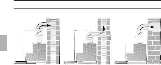
Die Abluft wird über einen Lüftungsschacht nach oben, oder direkt durch die Außenwand ins Freie geleitet.
DDie Abluft darf weder in einen in Betrieb befindlichen Rauchoder Abgaskamin noch in einen Schacht, welcher der Entlüftung von Aufstellungsräumen von Feuerstätten dient, abgegeben werden.
Bei der Ableitung von Abluft sind die behördlichen und gesetzlichen Vorschriften (z. B. Landesbauordnungen) zu beachten.
Bei Abführung der Luft in nicht in Betrieb befindliche Rauchoder Abgaskamine ist die Zustimmung des zuständigen Schornsteinfegermeisters einzuholen.
DBei Abluftbetrieb der Dunstabzugshaube und gleichzeitigem Betrieb schornsteinabhängiger Feuerungen (wie z. B. Gas-, Öloder Kohleheizgeräte, Durchlauferhitzer, Warmwasserbereiter) muss für ausreichend Zuluft gesorgt werden, die von der Feuerstätte zur Verbrennung benötigt wird.
Ein gefahrloser Betrieb ist möglich, wenn der Unterdruck im Aufstellraum der Feuerstätte von 4 Pa (0,04 mbar) nicht überschritten wird.
Dies kann erreicht werden, wenn durch nicht verschließbare Öffnungen, z. B. in Türen, Fenstern und in Verbindung mit Zuluft-/Abluftmauerkasten oder durch andere techn. Maßnahmen, wie gegenseitige Verriegelung o. ä., die Verbrennungsluft nachströmen kann.
Bei nicht ausreichender Zuluft besteht Vergiftungsgefahr durch zurückgesaugte Verbrennungsgase.
Ein Zuluft-/Abluftmauerkasten allein stellt die Einhaltung des Grenzwertes nicht sicher.
Anmerkung: Bei der Beurteilung muss immer der gesamte Lüftungsverbund der Wohnung beachtet werden. Bei Betrieb von Kochgeräten, z. B. Kochmulde und Gasherd wird diese Regel nicht angewendet.
Wenn die Dunstabzugshaube im Umluftbetrieb – mit Aktivkohlefilter – verwendet wird, ist der Betrieb ohne Einschränkung möglich.
10
Vor der Montage
Bei Abluftbetrieb sollte in der Dunstabzugshaube eine Rückstauklappe eingebaut werden, wenn sie nicht im Abluftrohr oder Mauerkasten vorhanden ist.
Ist dem Gerät keine Rückstauklappe beigelegt, kann sie über den Fachhandel bezogen werden (siehe Sonderzubehör in der Gebrauchsanleitung).
Montieren der Rückstauklappe:
1.Schutzgitter im Luftstutzen ausschneiden.
2.Rückstauklappe in die Lageröffnungen am Luftstutzen einsetzen.
Wird die Abluft durch die Außenwand geleitet, sollte ein Teleskop-Mauerkasten verwendet werden.
Optimale Leistung der Dunstabzugshaube:
Kurzes, glattes Abluftrohr.
Möglichst wenig Rohrbögen.
Möglichst große Rohrdurchmesser (am besten L 120 mm ) und große Rohrbögen.
Der Einsatz von langen, rauhen Abluftrohren, vielen Rohrbögen oder kleineren Rohrdurchmessern führt zu einer Abweichung von der optimalen Luftleistung und gleichzeitig zu einer Geräuscherhöhung.
DownloadedRundrohre:
Wir empfehlen |
|
|
|
from |
|
|
|
Innendurchmesser mind. 120 mm. |
|
|
|
Flachkanäle müssen einen gleichwerti- |
|
|
|
www |
|
|
|
gen Innenquerschnitt wie Rundrohre mit |
|
|
|
100/120 mm Innendurchmesser haben. |
|
|
|
|
. |
|
|
Sie sollten keine scharfen Umlenkun- |
|
|
|
Dichtstreifen einsetzen. |
vandenborre |
|
|
gen haben. |
|
|
|
L 100 mm ca. 078 cm2 |
|
|
|
L 120 mm ca. 113 cm2 |
|
|
|
Bei abweichenden Rohrdurchmessern: |
|
|
|
|
|
. |
|
Bei Abluftbetrieb für ausreichend Zuluft |
be |
||
|
|
||
sorgen.
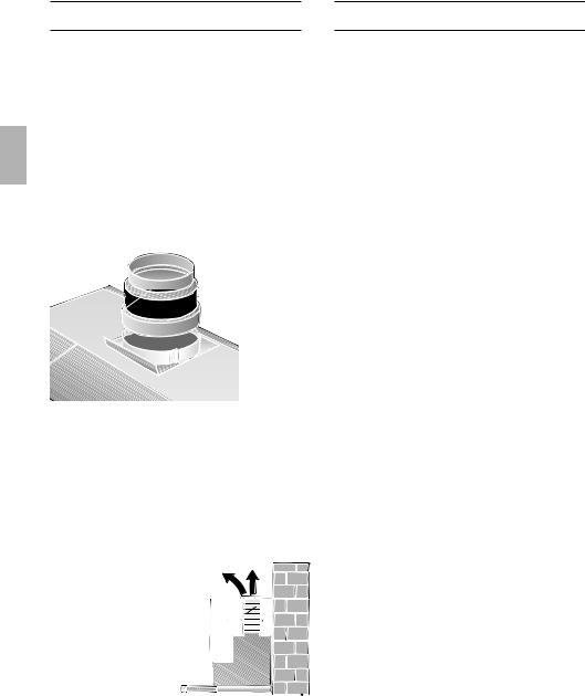
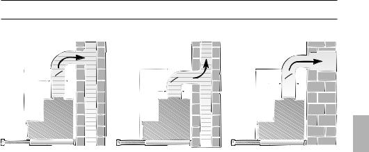
Abluft nach oben:
Dazu Öffnung in der Decke des Oberschrankes, mit Auskerbung für Elektro-
Anschlußkabel herstellen.
– Schablone OI liegt bei –.
287 |
313 |
|
|
133 |
|
|
195 |
170 |
|
|
250 |
21


 32
32
600 |
|
|
120 |
|
|
243 |
512 |
|
269 |
||
185 |
||
|
90
80 |
250 |
115 |
|
|
32 |
MIND. 30 |
|
|
|
280 |
598 |
|
443 |
|
280 |
- |
|
|
11
Vor der Montage
Abluft direkt nach hinten:
– innerhalb des Oberschrankes –.
Dazu Öffnung in der Rückwand des Oberschrankes, mit Auskerbung für Elektro-Anschlußkabel herstellen.
Anschluss Abluftrohr L 100 mm:
Schutzgitter im Luftaustritt ausschneiden.
Reduzierstutzen (beiliegend oder im Fachhandel erhältlich) am Luftaustritt befestigen.
Anschluss Abluftrohr L 120 mm:
Schutzgitter im Luftaustritt ausschneiden.
Umluftbetrieb
Mit Aktivkohlefilter, wenn keine Möglichkeit für Abluftbetrieb vorhanden ist.
Das komplette |
|
Montage-Set können |
|
Sie beim Fach- |
|
handel erwerben. |
O |
Die entsprechenden |
100 |
120 |
Zubehör-Nummern finden Sie auf der letzten Seite der Gebrauchsanleitung.
12
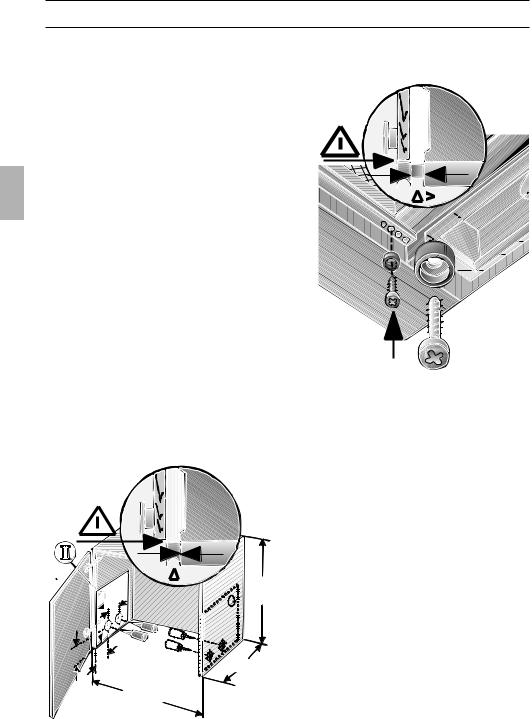
Auf Mindestabstand Kochstellen – |
DownloadedDie Lage der Griffleiste (Maß ) kann |
Vorbereiten Oberschrank |
|
Dunstabzugshaube von 650 mm (bei Gas- |
durch einen Anschlag nach vorne |
|
from |
Kochstelle) bzw. 430 mm (bei Elektro- |
versetzt werden. |
Kochstellen) achten. |
|
Diese Dunstabzugshaube ist zum Ein- |
|
|
|
bauen in einen Oberschrank mit folgenden |
|
|
|
Abmessungen vorgesehen: |
|
|
|
Breite: 600 mm |
|
|
|
Tiefe: 280 bis 350 mm |
|
|
|
Höhe: mind. 300 mm. |
|
|
|
Vorbereiten: |
0 |
. |
|
1. Schrankboden – falls vorhanden – |
|||
|
|||
|
be |
||
entfernen. |
|
||
|
|
||
Die Stabilität des Schrankes muss |
|
|
|
gewährleistet sein. |
|
|
|
2. Je zwei Befestigungspunkte – rechts |
|
|
|
und links – an den Schrankinnenseiten |
|
|
|
anreißen und mit Stichel vorstechen. |
|
|
Wenn gebohrt wird:
L 2 mm – max. 10 mm tief.
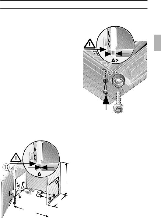
Achtung:
Zum Anreißen der Befestigungspunkte beiliegende Schablone OII verwenden.
Die Befestigungspunkte auf der Schablone sind so festgelegt, dass eine 20 mm dicke Griffleiste korpusbündig montiert werden kann.
|
=0 |
|
MIND |
170 |
300. |
|
|
21 |
280-350 |
32 |
|
|
600 |
Bei Schranktiefen von mehr als 280 mm kann das Gerät nach hinten versetzt werden,
. . . wenn z. B. die Lichtleiste der
. . . Einbauküche nach hinten versetzt ist,
. . . wenn z. B. die Griffleiste mehr als
. . . 20 mm dick ist.
Dazu die Schablone OII entsprechend weiter hinten anlegen.
13

Vorbereiten Oberschrank |
Einbauen in den Oberschrank |
|
3. Beiliegende Befestigungsschienen aus- |
1. DownloadedFilterrahmen abnehmen (siehe |
|
richten und festschrauben. |
Gebrauchsanleitung). |
|
Die Dicke der Schrankseitenwände |
2. Schranktüre ausrichten, wenn Scharnier |
|
from |
||
(16 mm oder 19 mm) beachten. Maß X. |
nach Einbau der Dunstabzugshaube |
|
|
|
www |
X=16MM |
X=19MM |
nicht mehr zugänglich ist. |
3. Dunstabzugshaube von unten in den |
||
|
|
. |
|
|
vandenborre |
|
|
Schrank heben und hochdrücken, bis |
|
|
Montagehilfe links und rechts einrastet. |
|
|
. |
|
|
be |
X |
|
|
Ist die lichte Schrankinnentiefe kleiner als 280 mm, muss die Rückwand 250 mm hoch entfernt werden.
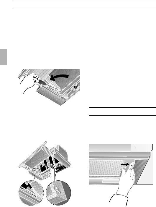
4.Filterauszug bis zum Anschlag ausziehen.
5.Zur Befestigung der Dunstabzugshaube jeweils 2 Schrauben links und rechts eindrehen, nicht festschrauben.
Dazu Dunstabzugshaube anheben.
6.Dunstabzugshaube im Schrank ausrichten und festschrauben.
14

Einbauen in den Oberschrank
7.Netzanschlusskabel durch die Öffnung im Oberschrank führen und die Rohrverbindung herstellen.
8.Elektrische Verbindung herstellen.
9.Wandabdeckung falls erforderlich auf das benötigte Maß kürzen (z. B. absägen) und am Oberschrank festschrauben.
Einbau einer Griffleiste:
An den Filterauszug muss eine Griffleiste montiert werden.
Die Griffleiste kann eine zum Küchenmöbel passende Holzleiste, oder eine als Sonderzubehör erhältliche Griffleiste sein (siehe Sonderzubehör).
1.Mit beiliegender Schablone OIII zwei Befestigungspunkte an der Griffleiste anreißen und mit Stichel vorstechen. Wenn gebohrt wird:
L 2 mm – max. 10 mm tief.
598 

 350
350 
14,5


2. DownloadedGriffleiste ausrichten und am Gerät mit
den zwei beiliegenden Schrauben fest- |
|
schrauben. |
from |
|
|
|
www |
|
. |
|
vandenborre |
|
. |
|
be |
3.Filterrahmen einbauen (siehe Gebrauchsanleitung).
Hinweis: Das Gehäuse der Dunstabzugshaube kann innerhalb des Oberschrankes verkleidet werden (z. B. mit Spanplatten).
Dabei beachten:
–Der Zwischenboden darf nicht auf das Gehäuse der Dunstabzugshaube aufgelegt werden.
–Die vordere Verkleidung nicht am Gehäuse befestigen.
–Zugänglichkeit für Kundendienst vorsehen.
Ausbauen:
Der Ausbau erfolgt in umgekehrter Reihenfolge.
Hinweis: Bei Umluftbetrieb müssen Aktivkohlefilter und Kunststoffhalter ausgebaut werden, damit die Befestigungsschrauben und die Montagehilfen zugänglich sind.
Gewicht in kg:
|
|
|
|
|
|
|
Abluft |
|
|
Umluft |
|
|
|
|
|
|
|
|
|
|
|
|
|
|
|
|
|
|
|
9,5 |
|
10,5 |
|
||
|
|
|
|
|
|
Konstruktionsänderungen im Rahmen der technischen Entwicklung bleiben vorenthalten.
15

Instructions for use:
Appliance description
Wall |
cupboard |
Filter drawer
Ventilator |
switches |
Light switch
Operating modes
Exhaust-air mode:
The extractor-hood fan extracts the kitchen vapours and conveys them through the grease filter into the atmosphere.
The grease filter absorbs the solid particles in the kitchen vapours.
The kitchen is kept almost free of grease and odours.
DWhen the extractor hood is operated in exhaust-air mode simultaneously with a different burner which also makes use of the same chimney (such as gas, oil or coal-fired heaters, continuous-flow heaters, hot-water boilers) care must be taken to ensure that there is an adequate supply of fresh air which will be needed by the burner for combustion.
Safe operation is possible provided that the underpressure in the room where the burner is installed does not exceed 4 Pa (0.04 mbar).
Downloaded |
|
|
Operating modes |
|
|
|
|
|
from |
|
|
This can be achieved if combustion air can |
|
|
flow through non-lockable openings, e.g. in |
|
|
www |
|
|
doors, windows and via the air- |
|
|
intake/exhaust-air wall box or by other |
|
|
|
. |
|
technical measures, such as reciprocal |
|
|
interlocking, etc. |
vandenborre |
|
|
|
|
If the air intake is inadequate, there is a |
|
|
risk of poisoning from combustion gases |
|
|
which are drawn back into the room. |
|
|
An air-intake/exhaust-air wall box by itself is |
. |
|
no guarantee that the limiting value will not |
be |
|
be exceeded.
Note: When assessing the overall requirement, the combined ventilation system for the entire household must be taken into consideration. This rule does not apply to the use of cooking appliances, such as hobs and ovens.
Unrestricted operation is possible if the extractor hood is used in recirculating mode
– with activated carbon filter.
Circulating-air mode:
An activated carbon filter must be fitted for this operating mode (see Filters and maintenance).
The complete installation set and replacement filters can be obtained from specialist outlets.
The corresponding accessory numbers can be found at the end of these operating instructions.
The extractor-hood fan extracts the kitchen vapours which are purified in the grease filter and activated carbon filter and then conveyed back into the kitchen.
The grease filter absorbs the grease particles in the kitchen vapours.
The activated carbon filter binds the odorous substances.
If no activated carbon filter is installed, it is not possible to bind the odorous substances in the cooking vapours.
16

Before using for the first time |
Downloaded |
|
|
|
|
Important notes: |
|
|
|
||
The Instructions for Use apply to several |
Before using your appliance for the first |
||||
versions of this appliance. Accordingly, |
time, please read these Instructions for |
||||
you may find descriptions of individual |
from |
|
|
|
|
Use carefully. They contain important |
|||||
features that do not apply to your |
information concerning your personal |
||||
specific appliance. |
safety as well as on usewwwand care of the |
||||
This extractor hood complies with all |
appliance. |
. |
|
|
|
|
|
|
|||
Please retain the operating and |
|||||
relevant safety regulations. |
|||||
|
installation instructions for a subsequent |
||||
Repairs should be carried out by |
owner. |
vandenborre |
|
||
qualified technicians only. |
|
||||
|
|
||||
Improper repairs may put the user at |
|
|
|||
considerable risk. |
|
. |
|||
|
|
be |
|||
|
|
|
|||
Do not use the appliance if damaged. |
Do not flambé food directly under the |
||||
The appliance is not intended for use |
extractor hood. |
|
|
|
|
Risk of grease filter catching fire due |
|||||
by young children or infirmed persons |
! to flames. |
|
|
|
|
without supervision. |
|
|
|
||
Restrictions apply to the use of the |
|||||
Young children should be supervised to |
|||||
ensure they do not play with the appliance. |
extractor hood over a solid-fuel burner |
||||
If the connecting cable for this |
(coal, wood, etc.). (See Installation |
||||
instructions). |
|
|
|
||
appliance is damaged, the cable must be |
|
|
|
||
|
|
|
|
||
replaced by the manufacturer or his |
|
|
|
|
|
customer service or a similarly qualified |
Gas hobs / gas cookers |
|
|
|
|
person in order to prevent serious injury to |
|
|
|
||
Always use gas hobs in a proper and |
|||||
the user. |
|||||
The appliance may be connected to |
safe manner. |
|
|
|
|
Important: |
|
|
|
||
the mains by a qualified technician only. |
|
|
|
||
The flames from the gas hob must always |
|||||
Dispose of packaging materials |
|||||
be covered by pots or pans. |
|
|
|
||
properly (see Installation instructions). |
The intense heat generated by the gas |
||||
|
flames could cause damage to the |
||||
Light bulbs must always be fitted when |
! extractor hood. |
|
the extractor hood is in use. |
||
|
||
Defective bulbs should be replaced |
|
|
immediately to prevent the remaining bulbs |
|
|
from overloading. |
|
|
Never operate the extractor hood |
|
|
without a grease filter. |
|
|
Overheated fat or oil can easily catch |
|
|
fire. |
|
|
If you are cooking with fat or oil, e.g. chips, |
|
|
etc., never leave the cooker unattended. |
|
17
Operating the extractor hood
Kitchen fumes are best eliminated by:
Switching ON the fan when you start cooking.
Switching OFF the fan
several minutes after you finish cooking.
Switching ON the fan:
1.Pull out the filter drawer by the handle.
The fan is now operating.
2.Select the desired fan setting.
Controls on the various models:
3 |
Setting 3 |
1 |
Setting 1 |
2 |
Setting 2 |
|
|
2 |
Setting 1 |
|
Light:Downloaded
0 |
from |
OFF |
|
|
www |
|
ON |
|
. |
|
vandenborre |
Note: the light can be used at any time, |
|
even if the filter drawer has been pushed in. |
|
|
. |
|
be |
|
Setting 2 |
2 |
|
|
Setting 3 |
2 |
3 |
1 |
Setting 1 |
|
|
0 |
OFF |
2 |
Setting 2 |
Switching OFF the fan:
Push in the filter drawer all the way.
Note: If the filter drawer is pulled out again, the fan starts operating at the last selected setting.
If you encounter a problem
If you have any questions or if a fault occurs, please call Customer Service.
(See list of Customer Service representatives).
When you call, please quote the following:
E-NR. FD
Enter the relevant numbers into the box above. The E-Nr. (product no.) and FD (production date) are shown on the nameplate which can be seen inside the extractor hood after the filter frame has been detached.
18

|
Downloaded |
|
|
||||
Metal-mesh grease filters have been |
|
|
|||||
Filters and maintenance |
|
|
|
|
|
|
|
|
Removing and installing the filter |
||||||
installed to filter grease particles out of |
frames |
|
from |
||||
the kitchen fumes. |
|
|
|||||
|
|
|
|
|
|
||
The filter mats are made of incombustible |
Removal: |
|
|
|
www |
||
metal. |
|
|
|
|
|||
1. Pull out the filter drawer all the way. |
|||||||
Attention: |
|||||||
|
|
|
|
. |
|
||
|
|
|
|
|
|
||
By cleaning the metal grease filters at |
2. Press the detents on the filter frames all |
||||||
|
|
|
|
vandenborre |
|||
As grease accumulates in the filter, there is |
the way in the direction of the arrow. |
||||||
an increased risk of the filter catching fire |
|
|
|
|
|
|
|
and the extractor hood may malfunction. |
|
|
|
|
|
|
|
Important: |
|
|
|
|
|
|
|
|
|
|
|
|
. |
||
appropriate intervals, the possibility of them |
|
|
|
|
|
be |
|
catching fire as a result of a build-up of heat |
|
|
|
|
|
||
|
|
|
|
|
|
||
such as occurs when deep-fat frying or |
|
|
|
|
|
|
|
roasting is taking place, is reduced. |
|
|
|
|
|
|
|
Cleaning the metal-mesh grease filters:
During normal operation (1 to 2 hours daily), the metal-mesh grease filters should be cleaned every 8 – 10 weeks.
The filters can be cleaned in the dishwasher.
However, the filters may be slightly discoloured.
Important: |
|
|
|
|
|
|
|
|
|
|
|
|
|
|
If the metal-mesh grease filters are very |
|
|
|
|
|
|
|
|
|
|
|
|
|
|
|
|
|
|
|
|
|
|
|
|
|
|
|
||
dirty, do NOT wash them in the |
|
|
|
|
|
|
|
|
|
|
|
|
|
|
|
|
|
|
|
|
|
|
|
|
|
|
|
||
dishwasher with other pots and pans. |
|
|
|
|
|
|
|
|
|
|
|
|
|
|
When cleaning by hand, soak the filter |
|
|
|
|
|
|
|
|
|
|
|
|
|
|
mats for several hours in a hot soap |
If there are two grease filters, remove |
|||||||||||||
solution. |
the front one first. |
|||||||||||||
Then brush them off, rinse thoroughly |
3. Fold the filter frame down at the side and |
|||||||||||||
and allow to drip dry. |
||||||||||||||
remove. |
||||||||||||||
To ensure the best possible results, |
||||||||||||||
|
|
|
|
|
|
|
|
|
|
|
|
|
||
use only original filters. |
Installation: |
|||||||||||||
|
1. Pull out the filter drawer all the way. |
|||||||||||||
|
2. Insert the filter frame at an angle into the |
|||||||||||||
|
holder, fold up and attach by pressing |
|||||||||||||
|
the detent all the way. |
|||||||||||||
|
If there are two grease filters, first |
|||||||||||||
|
insert the rear filter frame and then the |
|||||||||||||
|
front filter frame (profiled edge) into the |
|||||||||||||
|
filter drawer. |
|||||||||||||
|
Ensure that the grease filters are |
|||||||||||||
|
securely positioned on both sides. |
|||||||||||||
19
Filters and maintenance
Activated carbon filter:
For filtering odours during circulating-air mode.
The activated carbon filter is installed above the grease filter(s) in the extractor hood.
1.Remove the grease filter(s) (see Filters and maintenance).
2.Insert the two enclosed plastic holders into the right and left sides of the extractor-hood housing and attach each holder with a screw (required only if installing an activated carbon filter for the first time).
3.Insert the activated carbon filter from below into the extractor-hood housing and lock into position on both sides.
Ensure that the edge of the activated carbon filter is underneath.
4.Re-install the grease filter (see Filters and maintenance).
 1.
1.


 2.
2.


 3.
3.
20
Cleaning and care
Disconnect the extractor hood from the electricity supply by pulling out the mains plug or switching it off at the fuse box.
At the same time as you clean the grease filters, clean off any grease from all accessible parts of the housing. This significantly reduces the fire hazard and ensures that the extractor hood performs as effectively as possible.
Use a hot detergent solution or a mild window cleaner to clean the canopy of the extractor hood.
Do not scrape off any dirt that has dried on but loosen it up with a damp cloth.
Do not use abrasive cleaning agents or sponges that could cause scratches.
Note: Do not use alcohol (spirit) on plastic parts, otherwise the surface may become matt in appearance.
Caution: Ensure that the kitchen is adequately ventilated. Avoid naked flames!
Clean the operating buttons with a mild soapy solution and a soft, damp cloth only. Do not use stainless-steel cleaner to clean the operating buttons.
Stainless steel surfaces:
Use a mild non-abrasive stainless steel cleaner.
Clean the surface in the same direction as it has been ground and polished.
Do not use any of the following to clean stainless steel surfaces: abrasive sponges, cleaning agents containing sand, soda, acid or chloride!
Aluminium, painted and plastic surfaces:
Use a soft, non-linting window cloth or micro-fibre cloth.
Do not use dry cloths.
Use a mild window cleaning agent.
Do not use aggressive, acidic or caustic cleaners.
Do not use abrasive agents.
1. |
DownloadedSwitch off the extractor hood and pull |
||||
Replacing the light bulb |
|||||
|
|
|
|
|
|
|
|
out the mains plug or switch off the |
|||
|
|
|
|
from |
|
|
|
electricity supply at the fuse box. |
|||
2. |
|
Pull out the filter drawer all the way. |
|||
3. |
|
|
|
www |
|
|
Pull the lamp cover forwards. |
||||
|
|
|
|
. |
|
|
|
|
|
||
|
|
|
|
|
|
|
|
|
|
|
|
|
|
|
|
|
|
|
|
|
|
|
|
|
|
|
|
|
|
|
|
|
|
|
|
. be
4.Replace the light bulbs. (Standard candle bulbs, max. 40 W, E14 socket).
5.Re-insert the lamp cover.
6.Plug appliance into mains again or switch on at the fuse box.
21
|
|
Installation Instructions: |
Downloaded |
|
|
|
|
|
|
|
|
|
|
|
|
|
|
|
|
Important information |
|
|
|
|
|
|
|
|
|
|
|
Old appliances are not worthless |
from |
|
|
|
|
The installation of the extractor hood |
|
||
|
|
rubbish. If they are disposed of in an |
above gas cooking devices, at a |
|
|
|
|
environment-friendly manner, valuable raw |
minimum height of 650 mm – Fig. 1 – is |
|
|
|
|
materials can be recovered for use again. |
permitted provided that the following |
|
|
|
|
|
www |
|
|
|
|
Before you dispose of an old appliance, |
|
. |
|
|
|
nominal heat loads (Hs) are not exceeded: |
|
||
|
|
make sure that it has been rendered |
Gas cookers |
vandenborre |
|
|
|
inoperative. |
Load of one hotplate |
max. 03.0 kW |
|
|
|
Your new appliance was protected on |
Load of all hotplates |
max. 08.3 kW |
|
|
|
|
|||
|
|
Load of the oven |
max. 03.9 kW |
|
|
|
|
its way to you by the packaging. None of |
|
||
|
|
Gas hobs |
|
. |
|
|
|
the materials cause pollution to the envi- |
max. 03.9 kW |
||
|
|
ronment and all can be recycled for use |
Load of one hotplate |
be |
|
|
|
Load of all hotplates |
max. 11.3 kW |
|
|
|
|
again. Please help to protect the |
|
||
|
|
|
|
|
|
|
|
environment and dispose of the packaging |
Gas glass-ceramic hotplate |
|
|
|
|
in an environment-friendly manner. |
The data on nominal heat loads do not |
|
|
|
|
You can obtain information about the best |
apply to gas glass-ceramic hotplates. |
|
|
|
|
Be sure to observe the instructions |
|
||
|
|
method disposing of old appliances and |
|
||
|
|
provided by the manufacturer of the |
|
||
|
|
packaging from your dealer or local |
|
||
|
|
hotplate. |
|
|
|
|
|
municipal council. |
|
|
|
|
|
|
|
|
|
|
|
The extractor hood can be used in |
Solid-fuel cookers |
|
|
|
|
The maximum nominal heat loads and |
|
||
|
|
either exhaust-air or recirculating mode. |
|
||
|
|
the minimum distance are the same as |
|
||
|
|
|
|
||
|
|
Always mount the extractor hood over |
for gas cookers. |
|
|
|
|
Installation of the extractor hood over a |
|
||
|
|
the centre of the hob. |
|
||
|
|
Minimum distance between electric |
solid-fuel burner which could constitute a |
|
|
|
|
potential fire hazard (e.g. due to flying |
|
||
|
|
hob and bottom edge of extractor hood: |
|
||
|
|
sparks) is only permitted if the burner is |
|
||
|
|
430 mm, Fig. 1. |
|
||
|
|
equipped with an enclosed, non- |
|
||
|
|
|
|
||
|
|
|
removable cover and all country-specific |
|
|
|
|
Additional notes concerning gas |
regulations are observed. This restriction |
|
|
|
|
cookers: |
does not apply to gas cookers and gas |
|
|
|
|
When installing gas hotplates, comply |
hobs. |
|
|
|
|
The smaller the gap between extractor |
|
||
|
|
with the relevant national statutory |
|
||
|
|
regulations (e.g. in Germany: Technische |
hood and hob, the greater the likelihood |
|
|
|
|
Regeln Gasinstallation TRGI). |
that rising steam will cause condensation |
|
|
to form on the hood.
The relevant regulations and installation notes provided by the manufacturer of the gas cooker must be observed in all cases.
The extractor hood may be installed next to only one full-height cupboard or high wall. Gap to be at least 50 mm.
22
Prior to installation
Exhaust-air mode
O 100 120
Downloaded
O |
O |
|
100 |
||
100 |
||
120 |
||
120 |
||
|
. be
The exhaust air is discharged upwards through a ventilation shaft or directly through the outside wall into the open.
DExhaust air should neither be directed into a smoke or exhaust flue that is currently used for other purposes, nor into a shaft that is used for ventilating rooms in which stoves or fireplaces are also located.
Exhaust air may be discharged in accordance with official and statutory regulations only (e.g. national building regulations).
Local authority regulations must be observed when discharging air into smoke or exhaust flues that are not otherwise in use.
DWhen the extractor hood is operated in exhaust-air mode simultaneously with a different burner which also makes use of the same chimney (such as gas, oil or coal-fired heaters, continuous-flow heaters, hot-water boilers) care must be taken to ensure that there is an adequate supply of fresh air which will be needed by the burner for combustion.
Safe operation is possible provided that the underpressure in the room where the burner is installed does not exceed 4 Pa (0.04 mbar).
This can be achieved if combustion air can flow through non-lockable openings, e.g. in doors, windows and via the air- intake/exhaust-air wall box or by other technical measures, such as reciprocal interlocking, etc.
If the air intake is inadequate, there is a risk of poisoning from combustion gases which are drawn back into the room.
An air-intake/exhaust-air wall box by itself is no guarantee that the limiting value will not be exceeded.
Note: When assessing the overall requirement, the combined ventilation system for the entire household must be taken into consideration. This rule does not apply to the use of cooking appliances, such as hobs and ovens.
Unrestricted operation is possible if the extractor hood is used in recirculating mode – with activated carbon filter.
23

Prior to installation
For operating in exhaust-air mode, a one-way flap should be mounted inside the extractor hood unless there is already one fitted in the outlet duct or wall ventilation box.
If no one-way flap was enclosed with the hood, it can be obtained from a specialist retailer (see section on optional accessories in the user instructions).
Installing the one-way flap:
1.Cut out the protective grid in the air-pipe connector.
2.Insert the one-way flap into the bearing apertures on the air-pipe connector.
If the exhaust air is going to be discharged into the open, a telescopic wall box should be fitted into the outside wall.
For optimum extractor hood efficiency:
Short, smooth air exhaust pipe.
As few bends in the pipe as possible.
Diameter of pipe to be as large as possible (ideal is L 120 mm ) and no tight bends in pipe.
If long, rough exhaust-air pipes, many pipe bends or smaller pipe diameters are used, the air extraction rate will no longer be at an optimum level and there will be an increase in noise.
DownloadedRound pipes: |
|
|
from |
|
|
We recommend |
|
|
Internal diameter at least. 120 mm. |
|
|
Flact ducts must have an internal |
|
|
cross-section that equates to that of |
|
|
round pipes with a 100/120wwwmm internal |
|
|
|
. |
|
diameter |
vandenborre |
|
|
|
|
There should be no sharp bends. |
|
|
L 100 mm approx. 078 cm2 |
|
|
L 120 mm approx. 113 cm2 |
|
|
If pipes have different diameters: |
|
|
Insert sealing strip. |
|
. |
For exhaust-air mode, ensure that |
be |
|
|
||
there is an adequate supply of fresh air.
Exhaust air flows upwards:
Cut a hole in the top of the wall cupboard, including a groove for the mains
cable.
– Template OI lis enclosed –.
287 |
313 |
|
|
133 |
|
170
21


 32
32
 600
600
195

 250
250
120 |
|
|
243 |
512 |
|
269 |
||
|
185


 90
90
80 |
250 |
115 |
|
|
32 |
MIND. 30 |
|
|
|
280 |
598 |
|
443 |
|
280 |
- |
|
|
24

Prior to installation
Exhaust flows straight out at the back:
– inside the wall cupboard –.
Cut a hole in the rear panel of the wall cupboard, including a groove for the mains cable.
Connecting the L 100 mm exhaust-air pipe:
Cut out the protective grid in the air outlet.
Attach the reducing connector (enclosed or can be obtained from specialist retailers) to the air outlet.
Connecting the L 120 mm exhaust-air pipe:
Cut out the protective grid in the air outlet.
Circulating-air mode
With activated carbon filter if exhaust-air mode is not possible.
The complete installation set can be obtained from specialist outlets. The corresponding accessory numbers can be found at the end of these operating instructions.
O  100 120
ElectricalDownloadedconnection
This is what you have to do:
1. Connect the green and yellow (Earth) |
|
|||||||
wire to the terminal in the plug marked |
|
|||||||
from |
|
|
|
|
|
|||
‘E’ or with the symbol ( |
|
|
|
|
|
), or |
|
|
|
|
|
|
|
|
|||
|
|
|
|
|
|
|||
coloured green or green and yellow. |
|
|||||||
www |
|
|||||||
2. Connect the blue (Neutral) wire to the |
|
|||||||
|
|
|
. |
|
||||
terminal in the plug marked ‘N’ or |
|
|||||||
coloured black. |
|
|
|
|
|
|||
3. Connect the brown (Live) wire to the |
|
|||||||
terminal marked ‘L’, or coloured red. |
|
|||||||
The extractor hood may only be |
|
|||||||
|
|
|
|
|
|
vandenborre |
||
connected to an earthed socket that has |
. |
|||||||
be |
||||||||
|
|
|
|
|
|
|
||
been installed according to the relevant regulations. If possible, site the earthed socket directly above the wall cupboard or in its immediate vicinity.
Electrical data:
Are to be found on the name plate inside the appliance after removal of the filter frame.
Before undertaking any repairs, always disconnect the extractor hood from the electricity supply.
Length of the connecting cable: 1.30 m.
If it is necessary to wire the extractor hood directly into the mains:
The extractor hood should only be connected to the electricity supply by a properly qualified electrician.
A separator must be installed in the household circuit. A suitable separator is a switch that has a contact gap of more than 3 mm and interrupts all poles. Such devices include circuit breakers and contactors.
This extractor hood corresponds to EC regulations concerning RF interference suppression.
25
Ensure that there is a minimum gap |
DownloadedA stop allows the handle (Dimension |
) |
Preparing the wall cupboard |
|
|
between hob and extractor hood of 650 |
to be positioned further forwards. |
|
mm (for gas hobs) or 430 mm (for electric |
from |
|
hobs). |
|
|
This extractor hood has been designed |
|
|
for installation inside a wall cupboard with |
|
|
the following dimensions: |
|
|
Width: 600 mm |
|
|
Depth: 280 bis 350 mm |
|
|
Height: at least 300 mm. |
|
|
Preparation: |
0 |
|
1. Remove bottom panel of cupboard – if |
. |
|
fitted. |
|
be |
The stability of the cupboard must be |
|
|
maintained. |
|
|
2. Mark two points – right and left – on the |
|
|
inside of the cupboard where the hood |
|
|
is to be mounted, and start the hole with |
|
|
a gimlet. |
|
|
Details for drilling:
L 2 mm – max. 10 mm deep.
Attention:
Use enclosed template OII for marking points where hood is to be mounted.
The mounting points shown on the template have been configured in such a way as to allow a 20 mm thick handle to be attached flush with the front edges of the cupboard.
|
=0 |
|
MIND |
170 |
300. |
|
|
21 |
280-350 |
32 |
|
|
600 |
If the cupboard depth is greater than 280 mm, the hood can be mounted further back,
. . . if the light strip under the cupboard
. . . units is mounted further back,
. . . if the handle is more than 20 mm thick.
Position the template OII further back.
26

Preparing the wall cupboard
3.Align and screw on the enclosed mounting rails.
Note the thickness of the sides of the cupboard (16 mm or 19 mm).
dimension X.
X=16MM X=19MM
X |
If the interior depth of the cupboard is less than 280 mm, the 250 mm high rear panel must be removed.
|
|
|
Downloaded |
|
||||||
|
|
Installation inside the wall |
||||||||
|
|
cupboard |
|
|
|
|
||||
|
|
|
|
|
|
|
|
|
|
|
|
|
1. |
Manual). |
from |
||||||
|
|
Remove the filter frames (see Operating |
||||||||
|
|
2. |
|
|
|
|
|
www |
||
|
|
If the hinges are no longer accessible |
||||||||
|
|
|
when the extractor hood has been |
|||||||
|
|
|
installed, align the cupboard .doors. |
|||||||
|
|
3. |
|
|
|
|
|
|
vandenborre |
|
|
|
Lift and push the extractor hood from |
||||||||
|
|
|
below into the cupboard until the |
|||||||
|
|
|
installation aids on the left and right lock |
|||||||
|
|
|
into position. |
|
|
|
|
|||
|
|
|
|
|
|
|
. |
|||
|
|
|
|
|
|
|
||||
|
|
|
|
|
|
|
|
|
|
be |
|
|
|
|
|
|
|
|
|
|
|
|
|
|
|
|
|
|
|
|
|
|
|
|
|
|
|
|
|
|
|
|
|
|
|
|
|
|
|
|
|
|
|
|
|
|
|
|
|
|
|
|
|
|
|
|
|
|
|
|
|
|
|
|
|
|
|
|
|
|
|
|
|
|
|
|
|
|
|
|
|
|
|
|
|
|
|
|
|
|
|
|
|
|
|
|
|
|
|
|
|
|
|
|
|
|
|
|
|
|
|
|
|
|
|
|
|
|
|
|
|
|
|
|
|
|
|
|
|
|
|
|
4.Pull out the filter drawer all the way.
5.Attach the extractor hood by screwing in 2 screws on the left and right. Do NOT tighten the screws. Raise the extractor hood.
6.Align the extractor hood in the cupboard and tighten the screws.
27

Installation inside the wall cupboard
7. Feed the mains connection cable |
2. |
through the aperture into the upper cupboard and connect the pipe.
8.Connect to the power supply.
9.If required, shorten the wall cover to the required size (e.g. saw off) and screw to the upper cupboard.
DownloadedAlign the handle and screw onto the |
|
|
from |
appliance with the two enclosed |
|
screws. |
|
|
www |
|
. |
|
vandenborre |
|
. |
|
be |
Attaching a handle:
A handle must be attached to the filter drawer.
This handle can either be a wooden strip that matches the kitchen
cupboards or a the handle that is available as an optional accessory (see section on optional accessories in the user instructions).
1.Mark two points on the handle with the enclosed template OIII and make holes with a bradawl.
If the holes are drilled:
L 2 mm – max. 10 mm deep.
598 

 350
350 
14,5


3.Insert the filter frames (see Operating Manual).
Note: The extractor hood housing inside the wall cupboard can be boarded up (e.g. with chipboard).
Please observe the following:
–The shelf must not be rest upon the extractor hood housing.
–The board at the front should not be attached to the housing.
–Provide access for customer service.
Removal:
The extractor hood is removed in reverse sequence.
Note: In circulating-air mode the activated carbon filter and plastic holder must be removed in order to gain access to the mounting screws and installation aids.
Weight in kg:
|
|
|
|
|
|
|
Exhaust air |
|
|
Re-circulating air |
|
|
|
|
|
|
|
|
|
|
|
|
|
|
|
|
|
||
|
9,5 |
|
|
10,5 |
|
|
|
|
|
|
|
|
|
|
|
|
|
The manufacturer reserves the right to make design alterations in the interests of technical development.
28

Mode d’emploi:
Description de l'appareil
Placard en |
Commutateur |
appui mural |
Eclairage |
Tiroir-filtre |
Commutateur à |
|
niveaux de puis- |
|
sance Ventilateur |
Modes de fonctionnement
Air évacué à l'extérieur:
Le ventilateur de la hotte aspire les buées de cuisson qui traversent un filtre à graisse avant de regagner l'atmosphère extérieure.
Ce filtre retient les particules grasses solides en suspension dans les buées de cuisson.
Les particules grasses ne se déposent plus dans la cuisine, les odeurs de cuisson disparaissent.
DSi la hotte évacue l'air à l'extérieur et si le logement comporte des moyens de chauffage (tels par ex. des appareils de chauffage au gaz, au fuel ou au charbon, chauffe-eau instantanés ou à accumulation) raccordés à une cheminée, veiller impérativement à ce que l'apport d'air soit suffisant pour assurer la marche du chauffage à combustion.
Un fonctionnement sans risque est possible si la dépression dans le local où le foyer de chauffage est implanté ne dépasse pas 4 Pascals (0,04 mbars).
 Loading...