


 Loading...
Safety Guidelines: Warning notices must be observed to ensure personal safety as well as that of others, and to protect the product and the connected equipment. These warning notices are accompanied by a clarification of the level of caution to be observed.
Qualified Personnel: This device/system may only be set up and operated in conjunction with this manual. Qualified personnel are only authorized to install and operate this equipment in accordance with established safety practices and standards.
Unit Repair and Excluded Liability:
•The user is responsible for all changes and repairs made to the device by the user or the user’s agent.
•All new components are to be provided by Siemens Milltronics Process Instruments.
•Restrict repair to faulty components only.
•Do not reuse faulty components.
Warning: Cardboard shipping package provides limited humidity and moisture protection. This product can only function properly and safely if it is correctly transported, stored, installed, set up, operated, and maintained.
This product is intended for use in industrial areas. Operation of this equipment in a residential area may cause interference to several frequency based communications.
Note: Always use product in accordance with specifications.
|
Copyright Siemens AG 2010. All Rights |
|
|
Disclaimer of Liability |
|
|
|
|
|
||
|
Reserved |
|
|
|
|
|
This document is available in bound version and in |
|
While we have verified the contents of this |
||
|
electronic version. We encourage users to purchase |
|
manual for agreement with the |
||
|
authorized bound manuals, or to view electronic |
|
instrumentation described, variations remain |
||
|
versions as designed and authored by Siemens |
|
possible. Thus we cannot guarantee full |
||
|
Milltronics Process Instruments. Siemens Milltronics |
|
agreement. The contents of this manual are |
||
|
Process Instruments will not be responsible for the |
|
regularly reviewed and corrections are |
||
|
contents of partial or whole reproductions of either |
|
included in subsequent editions. We welcome |
||
|
bound or electronic versions. |
|
all suggestions for improvement. |
||
|
|
|
|
Technical data subject to change. |
|
MILLTRONICS®is a registered trademark of Siemens Milltronics Process Instruments.
Contact SMPI Technical Publications |
European Authorized Representative |
at the following address: |
|
Technical Publications |
Siemens AG |
Siemens AG |
Industry Sector |
Siemens Milltronics Process Instruments |
76181 Karlsruhe |
1954 Technology Drive, P.O. Box 4225 |
Deutschland |
Peterborough, Ontario, Canada, K9J 7B1 |
|
Email: techpubs.smpi@siemens.com |
|
•For a selection of Siemens Milltronics level measurement manuals, go to:
www.siemens.com/processautomation. Under Process Instrumentation, select Level Measurement and then go to the manual archive listed under the product family.
•For a selection of Siemens Milltronics weighing manuals, go to:
www.siemens.com/processautomation. Under Weighing Technology, select Continuous Weighing Systems and then go to the manual archive listed under the product family.
© Siemens AG 2010

Table of Contents |
|
Safety Notes ........................................................................................................................................... |
1 |
Safety marking symbols ............................................................................................................ |
1 |
FCC Conformity ...................................................................................................................................... |
1 |
CE Electromagnetic Compatibility (EMC) Conformity ................................................................... |
2 |
Industry Canada .................................................................................................................................... |
2 |
The Manual ............................................................................................................................................ |
3 |
Technical Support ................................................................................................................................. |
3 |
SITRANS LR560 Overview ................................................................................................ |
5 |
Programming ................................................................................................................................ |
5 |
Local Display Interface (LDI) .................................................................................................... |
6 |
Versions .................................................................................................................................................. |
6 |
Applications .................................................................................................................................. |
6 |
Approvals and Certificates ....................................................................................................... |
6 |
Specifications .................................................................................................................... |
7 |
Power............................................................................................................................................. |
7 |
Performance................................................................................................................................. |
7 |
Interface ........................................................................................................................................ |
8 |
Mechanical................................................................................................................................... |
8 |
Environmental .............................................................................................................................. |
9 |
Process.......................................................................................................................................... |
9 |
Approvals .................................................................................................................................... |
10 |
Programmer (infrared keypad) .............................................................................................. |
10 |
Dimensions ........................................................................................................................................... |
11 |
Universal Slotted Flange ......................................................................................................... |
15 |
Installation ........................................................................................................................ |
16 |
Mounting location ............................................................................................................................... |
17 |
Nozzle location .......................................................................................................................... |
17 |
Aimer Adjustment ..................................................................................................................... |
19 |
Air Purging System ............................................................................................................................. |
20 |
Purge Connection ..................................................................................................................... |
20 |
Wiring ................................................................................................................................ |
22 |
Power ..................................................................................................................................................... |
22 |
Connecting SITRANS LR560 ............................................................................................................. |
22 |
Connecting HART ...................................................................................................................... |
23 |
Wiring setups for hazardous area installations ................................................................ |
24 |
Non-incendive and Dust Ignition Proof wiring (US/Canada) ......................................... |
24 |
Instructions specific to hazardous area installations ...................................................... |
25 |
Local operation ................................................................................................................ |
26 |
Activating SITRANS LR560 ............................................................................................................... |
26 |
The LCD Display ........................................................................................................................ |
27 |
Handheld Programmer ........................................................................................................... |
28 |
Programming SITRANS LR560 ............................................................................................... |
29 |
Quick Start Wizard via the LDI push buttons ............................................................................... |
32 |
Quick Start Wizard via the handheld programmer ..................................................................... |
32 |
Contents of Table
i

Table of Contents
Requesting an Echo Profile .............................................................................................................. |
35 |
Level application example ................................................................................................................ |
36 |
Operating via SIMATIC PDM ......................................................................................... |
37 |
Functions in SIMATIC PDM .............................................................................................................. |
37 |
SIMATIC PDM Version ...................................................................................................................... |
37 |
Electronic Device Description (EDD) .................................................................................... |
37 |
Configuring a new device ....................................................................................................... |
38 |
Quick Start Wizard via SIMATIC PDM .......................................................................................... |
38 |
Changing parameter settings using SIMATIC PDM ................................................................... |
41 |
Parameters accessed via pull-down menus ...................................................................... |
42 |
Diagnostics ................................................................................................................................. |
50 |
Security ........................................................................................................................................ |
52 |
Operating via FDT (Field Device Tool) ......................................................................... |
53 |
Device Type Manager (DTM) .......................................................................................................... |
53 |
SITRANS DTM ..................................................................................................................................... |
53 |
The Instrument EDD ........................................................................................................................... |
53 |
Configuring a new device via FDT .................................................................................................. |
53 |
Operating via AMS Device Manager ........................................................................... |
54 |
Functions in AMS Device Manager ............................................................................................... |
54 |
Features of AMS Device Manager ....................................................................................... |
54 |
Device Description (DD) .......................................................................................................... |
54 |
Configuring a new device ....................................................................................................... |
55 |
Startup ......................................................................................................................................... |
55 |
Pull-down menu access .......................................................................................................... |
56 |
Device configuration ................................................................................................................ |
56 |
Quick Start Wizard via AMS Device Manager .................................................................. |
57 |
Maintenance and Diagnostics ........................................................................................................ |
64 |
Communication .................................................................................................................................... |
66 |
Security ................................................................................................................................................. |
66 |
Device Diagnostics ............................................................................................................................. |
67 |
Password Protection ................................................................................................................ |
68 |
User Manager Utility ................................................................................................................ |
68 |
AMS Menu Structure ..................................................................................................... |
69 |
Parameter Reference ..................................................................................................... |
76 |
Quick Start .................................................................................................................................. |
76 |
Quick Start Wizard .......................................................................................................... |
76 |
AFES (Auto False Echo Suppression) Wizard .......................................................... |
77 |
Copy Parameters to Display ......................................................................................... |
78 |
Copy Parameters from Display .................................................................................... |
78 |
Copy Firmware to Display ............................................................................................. |
78 |
Copy Firmware from Display ........................................................................................ |
79 |
Setup ............................................................................................................................................ |
79 |
Device ................................................................................................................................ |
79 |
Sensor ............................................................................................................................... |
80 |
Calibration ......................................................................................................................... |
81 |
Rate..................................................................................................................................... |
82 |
Fail-safe ............................................................................................................................. |
84 |
Analog Output Scaling ................................................................................................... |
85 |
ii |
|

Signal Processing............................................................................................................ |
88 |
TVT setup........................................................................................................................... |
93 |
TVT shaper........................................................................................................................ |
94 |
Measured Values ............................................................................................................ |
95 |
Diagnostics ................................................................................................................................. |
96 |
Fault Reset ........................................................................................................................ |
96 |
Echo Profile....................................................................................................................... |
96 |
Trend .................................................................................................................................. |
97 |
Peak Values ...................................................................................................................... |
97 |
Electronics Temperature ............................................................................................... |
97 |
Remaining Device Lifetime ........................................................................................... |
98 |
Remaining Sensor Lifetime ........................................................................................ |
100 |
Service........................................................................................................................ |
.............. 103 |
Demo Mode ................................................................................................................... |
103 |
Master Reset................................................................................................................. |
103 |
Powered Hours............................................................................................................. |
103 |
Power-on Resets.......................................................................................................... |
103 |
LCD Backlight ................................................................................................................ |
103 |
LCD Contrast.................................................................................................................. |
104 |
Service Schedule ......................................................................................................... |
104 |
Calibration Schedule ................................................................................................... |
107 |
Communication.................................................................................................................. |
..... 109 |
Device Address............................................................................................................. |
109 |
Remote Lockout ............................................................................................................ |
110 |
Security....................................................................................................................... |
.............. 110 |
Write Protection ........................................................................................................... |
110 |
Language....................................................................................................................... |
........... 110 |
Appendix A: Alphabetical Parameter List ................................................................ |
111 |
Appendix B: Troubleshooting ..................................................................................... |
114 |
Communication Troubleshooting .................................................................................................. |
114 |
Device Status Icons ......................................................................................................................... |
115 |
General Fault Codes ......................................................................................................................... |
116 |
Operation Troubleshooting ............................................................................................................ |
119 |
Appendix C: Maintenance ........................................................................................... |
121 |
Unit Repair and Excluded Liability ................................................................................................ |
121 |
Appendix D: Technical Reference ............................................................................. |
122 |
Principles of Operation .................................................................................................................... |
122 |
Process Variables ................................................................................................................... |
122 |
Echo Processing ............................................................................................................................... |
123 |
Process Intelligence ............................................................................................................... |
123 |
Echo Selection ......................................................................................................................... |
123 |
Measurement Range ............................................................................................................. |
127 |
Measurement Response ....................................................................................................... |
128 |
Analog Output .................................................................................................................................... |
128 |
Sensor Mode (2.2.2.) ............................................................................................................... |
129 |
Current Output Function (2.6.1.) ........................................................................................... |
129 |
Loss of Echo (LOE) .................................................................................................................. |
130 |
Temperature derating curve ......................................................................................................... |
131 |
Loop power ......................................................................................................................................... |
132 |
|
iii |
Contents of Table

Table of Contents
Typical Connection Drawing ................................................................................................ |
132 |
Allowable operating area of SITRANS LR560 .................................................................. |
133 |
Startup Behavior ..................................................................................................................... |
133 |
Appendix E: HART Communications ......................................................................... |
134 |
SIMATIC PDM ................................................................................................................................... |
134 |
HART Electronic Device Description (EDD) ................................................................................ |
134 |
HART Communicator 375 Menu Structure ................................................................................ |
135 |
HART Version ..................................................................................................................................... |
139 |
Burst Mode ............................................................................................................................... |
139 |
HART Multidrop Mode ........................................................................................................... |
139 |
Appendix F: Firmware Revision History .................................................................... |
140 |
Glossary .......................................................................................................................... |
141 |
Index ................................................................................................................................ |
144 |
LCD menu structure ...................................................................................................... |
147 |
iv

Safety Notes
Special attention must be paid to warnings and notes highlighted from the rest of the text by grey boxes.
WARNING symbol relates to a caution symbol on the product, and means that failure to observe the necessary precautions can result
in death, serious injury, and/or considerable material damage. WARNING symbol, used when there is no corresponding caution
symbol on the product, means that failure to observe the necessary precautions can result in death, serious injury, and/or considerable material damage.
Note: means important information about the product or that part of the operating manual.
Safety marking symbols
In manual |
On product |
Description |
Earth (ground) Terminal
Protective Conductor Terminal
(Label on product: yellow background.) WARNING: refer to accompanying documents (manual) for details.
FCC Conformity
US Installations only: Federal Communications Commission (FCC) rules
WARNING: Changes or modifications not expressly approved by Siemens Milltronics could void the user’s authority to operate the
equipment.
Notes:
•This equipment has been tested and found to comply with the limits for a Class A digital device, pursuant to Part 15 of the FCC Rules. These limits are designed to provide reasonable protection against harmful interference when the equipment is operated in a commercial environment.
•This equipment generates, uses, and can radiate radio frequency energy and, if not installed and used in accordance with the instruction manual, may cause harmful interference to radio communications. Operation of this equipment in a residential area is likely to cause harmful interference to radio communications, in which case the user will be required to correct the interference at his own expense.
LR560 SITRANS
7ML19985KB01 |
SITRANS LR560 (mA/HART) – INSTRUCTION MANUAL |
Page 1 |

CE Electromagnetic Compatibility (EMC) Conformity
This equipment has been tested and found to comply with the following EMC Standards:
|
|
EMC Standard |
Title |
|
|
CISPR 11:2004/EN |
Limits and methods of measurements of radio |
|
|
disturbance characteristics of industrial, scientific, |
|
|
|
55011:1998+A1:1999&A2:2002, CLASS B |
|
|
|
and medical (ISM) radio-frequency equipment. |
|
|
|
|
|
|
|
|
|
|
|
EN 61326:1997+A1:1998+A2:2001+A3:2003 |
Electrical Equipment for Measurement, Control and |
|
|
(IEC 61326:2002) |
Laboratory Use – Electromagnetic Compatibility. |
|
|
|
|
|
|
|
Electromagnetic Compatibility (EMC) Part 4-2:Testing |
|
|
EN61000-4-2:2001 |
and measurement techniques – Electrostatic |
|
|||
|
|
|
discharge immunity test. |
|
|
|
|
|
|
|
Electromagnetic Compatibility (EMC) Part 4-3: |
LR560 |
|
EN61000-4-3:2002 |
Testing and measurement techniques – Radiated, |
|
|
radio-frequency, electromagnetic field immunity test. |
|
|
|
|
|
|
|
|
|
SITRANS |
|
|
Electromagnetic Compatibility (EMC) Part 4-4: |
|
EN61000-4-4:2004 |
Testing and measurement techniques – Electrical |
|
|
|
||
|
|
|
fast transient/burst immunity test. |
|
|
|
|
|
|
|
Electromagnetic Compatibility (EMC) Part 4-5: |
|
|
EN61000-4-5:2001 |
Testing and measurement techniques – Surge |
|
|
|
immunity test. |
|
|
|
|
|
|
|
Electromagnetic Compatibility (EMC) Part 4-6: |
|
|
EN61000-4-6:2004 |
Testing and measurement techniques – Immunity to |
|
|
conducted disturbances, induced by radio-frequency |
|
|
|
|
|
|
|
|
fields. |
|
|
|
|
|
|
|
Electromagnetic Compatibility (EMC) Part 4-8: |
|
|
EN61000-4-8:2001 |
Testing and measurement techniques – Power |
|
|
|
frequency magnetic field immunity test. |
|
|
|
|
Industry Canada
a)Operation is subject to the following two conditions: (1) this device may not cause interference, and (2) this device must accept any interference, including interference that may cause undesired operation of the device.
b)This device shall be installed and operated in a completely enclosed container to prevent RF emission which otherwise can interfere with aeronautical navigation. Installation shall be done by trained installers, in strict compliance with the manufacturer’s instructions.
c)The use of this device is on a “no-interference, no-protection” basis. That is, the user shall accept operations of high-powered radar in the same frequency band which may interfere with or damage this device. On the other hand, level probing devices found to interfere with primary licensing operations will be required to be removed at the user’s expense.
Page 2 |
SITRANS LR560 (mA/HART) – INSTRUCTION MANUAL |
7ML19985KB01 |

d)This level probing device is only permitted for installation inside enclosed containers. The installer/user of this device shall ensure that it is at least 10 km from the Penticton radio astronomy station (British Columbia latitude: 49° 19' 12" N, longitude: 119° 37'12" W). For devices not meeting this 10 km separation (e.g. the Okanagan Valley, British Columbia) the installer/ user must coordinate with and obtain the written concurrence of the Director of the Penticton radio astronomy station before the equipment can be installed or operated. The Penticton contact is Tel: 250-493-2277/ fax: 250-493-7767. (In case of difficulty, the Manager, Radio Equipment Standards, Industry Canada, may also be contacted.)
The Manual
Notes:
•This product is intended for use in industrial areas. Operation of this equipment in a residential area may cause interference to several frequency based communications.
•Please follow the installation and operating procedures for a quick, trouble-free installation and to ensure the maximum accuracy and reliability of your SITRANS LR560.
•This manual applies to the SITRANS LR560 (mA/HART) only.
This manual will help you set up your SITRANS LR560 for optimum performance. We always welcome suggestions and comments about manual content, design, and accessibility. Please direct your comments to techpubs.smpi@siemens.com.
For other Siemens Milltronics level measurement manuals, go to: www.siemens.com/level and look under Level Measurement.
Application Example
The application example used in this manual illustrates a typical installation using SITRANS LR560. (See Level application example on page 36.) Because there is often a range of ways to approach an application, other configurations may also apply.
In all examples, substitute your own application details. If the example does not apply to your application, check the applicable parameter reference for the available options.
Technical Support
Support is available 24 hours a day.
To find your local Siemens Automation Office address, phone number and fax number go to: www.siemens.com/automation/partner
•Click on the tab Contact, select Service, then click Service again to find your product group (+Automation Technology > +Sensor Systems >+Process Instrumentation > +Level Measurement > +Continous). Select Radar.
•Select the country followed by the City/Region.
•Select Technical Support under Service.
(continued on next page)
LR560 SITRANS
7ML19985KB01 |
SITRANS LR560 (mA/HART) – INSTRUCTION MANUAL |
Page 3 |

SITRANS LR560
For on-line technical support go to: www.siemens.com/automation/support-request
•Enter the device name (SITRANS LR560) or order number, then click on Search, and select the appropriate product type. Click on Next.
•You will be prompted to enter a keyword describing your issue. Then either browse the relevant documentation, or click on Next to email a detailed description of your issue to Siemens Technical Support staff.
Siemens IA/DT Technical Support Center: phone |
+49 (0)911 895 7222 |
Abbreviations and Identifications
Short |
Long Form |
Description |
Units |
|
form |
||||
|
|
|
||
CE / FM / |
Conformité Européene / Factory Mutual / |
safety approval |
|
|
CSA |
Canadian Standards Association |
|
|
|
DCS |
Distributed Control System |
control room apparatus |
|
|
dK |
dielectric constant |
|
|
|
|
|
|
|
|
EDD |
Electronic Device Description |
|
|
|
ESD |
Electrostatic Discharge |
|
|
|
|
|
|
|
|
FMCW |
Frequency Modulated Continuous Wave |
radar principle |
|
|
Ii |
Input current |
|
mA |
|
Io |
Output current |
|
mA |
|
LCD |
Liquid Crystal Display |
|
|
|
|
|
|
|
|
LDI |
Local Display Interface |
removable display with push |
||
buttons |
|
|||
|
|
|
||
|
|
view outputs via LCD display; |
||
LUI |
Local User Interface |
make modifications via push |
||
|
|
buttons or handheld programmer |
||
|
|
|
|
|
μs |
microsecond |
10-6 |
Second |
|
PA |
Process Automation (PROFIBUS) |
|
|
|
|
|
|
|
|
PED |
Pressure Equipment Directive |
safety approval |
|
|
ppm |
parts per million |
|
|
|
|
|
|
|
|
PV |
Primary Value |
measured value |
|
|
SELV |
Safety extra low voltage |
|
|
|
|
|
|
|
|
SV |
Secondary Value |
equivalent value |
|
|
TB |
Transducer Block |
|
|
|
|
|
|
|
|
TVT |
Time Varying Threshold |
sensitivity threshold |
|
|
Ui |
Input voltage |
|
V |
|
Uo |
Output voltage |
|
V |
|
Page 4 |
SITRANS LR560 (mA/HART) – INSTRUCTION MANUAL |
7ML19985KB01 |
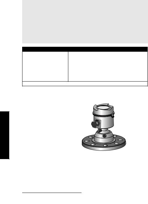
SITRANS LR560 Overview
SITRANS LR560 is a 2-wire, 78 GHz FMCW radar level transmitter for continuous monitoring of solids in vessels to a range of 100 m (329 ft). The plug and play performance is ideal for all solids applications, including those with extreme dust and high temperatures to +200 °C (+392 °F). The device is an electronic circuit coupled to a lens antenna and flange for quick and easy positioning.
The main benefits of using 78 GHz over devices using lower frequency are:
•very narrow beam, so device is insensitive to mounting nozzle interference and vessel obstructions.
•short wavelength yields very good reflection properties on sloped solids, so aiming
towards material angle of repose is usually not necessary.
The technology is very tolerant to buildup on the lens antenna, however an air purge inlet is provided for periodic cleaning if required.
SITRANS LR560 supports HART communication protocol, and SIMATIC PDM software. Signals are processed using Process Intelligence which has been field-proven in over 1,000,000 applications worldwide (ultrasonic and radar).
LR560 SITRANS
Programming
SITRANS LR560 is very easy to install and configure via an optional graphical local display interface. You can modify the built-in parameters either locally via the push buttons or using the infra-red handheld programmer, or from a remote location using one of the following options:
•HART (using 375 handheld Field Communicator, SIMATIC PDM, AMS, Pactware FDT/ DTM)
•PROFIBUS PA (using SIMATIC PDM, FDT [such as PACTware or Fieldcare]) (See SITRANS LR560 (PROFIBUS PA) Instruction Manual for more information.)
•Foundation Fieldbus FF (using handheld 375 Field Communicator, FF host system or AMS Device Manager) [See SITRANS LR560 (Foundation Fieldbus) Instruction Manual for more information.]
Once programmed, the graphic Local Display Interface (LDI) can be removed if desired and used to transfer parameters to multiple SITRANS LR560s.
7ML19985KB01 |
SITRANS LR560 (mA/HART) – INSTRUCTION MANUAL |
Page 5 |

SITRANS LR560
Local Display Interface (LDI)
•LDI may be ordered installed or added later as
an option
•can be mounted in 1 of 4 positions at 90 degree intervals, for easy viewing after installation
• displays level and diagnostic information including echo profile and trend over time
• backlit for easy viewing in dimly lit areas
•allows you to copy parameters from one device to another
•provides high speed firmware transfer capabilities for future upgrades
Versions
Two different versions of the LR560 are available:
•40 m range, +100 °C maximum process temperature
•100 m range, +200 °C maximum process temperature
Applications
•solids bulk storage vessels
•cement powder, plastic powder/pellets, grain, flour, coal, and other applications
Approvals and Certificates
SITRANS LR560 is available with General Purpose approval, or for Hazardous areas. For details, see Approvals on page 10.
Application |
LR560 Version |
Approval Rating |
Valid for: |
|
Type |
||||
|
|
|
||
|
|
|
|
|
Non- |
General |
CSAUS/C, FM, CE, C-TICK |
N. America, |
|
hazardous |
Purpose |
Europe |
||
|
||||
|
Non-Sparking/ |
ATEX II 3G Ex nA/nL IIC T4 Gc |
Europe |
|
|
Energy Limited |
|||
|
|
|
||
|
|
|
|
|
|
|
ATEX II 1D, 1/2D, 2D |
Europe and |
|
|
|
IECEx Cert. SIR 09.0149X |
||
|
|
International |
||
|
Dust Ignition |
Ex ta IIIC T139 °C Da |
||
Hazardous |
|
|||
Proof |
FM/CSA: |
|
||
|
|
|||
|
|
Class II, Div. 1, Groups E, F, G |
US/Canada |
|
|
|
Class III T4 |
|
|
|
|
|
|
|
|
Non-incendive |
FM/CSA: |
US/Canada |
|
|
Class I, Div. 2, Groups A, B, C, D T4 |
|||
|
|
|
||
|
|
|
|
Page 6 |
SITRANS LR560 (mA/HART) – INSTRUCTION MANUAL |
7ML19985KB01 |

Specifications
Note: Siemens Milltronics makes every attempt to ensure the accuracy of these specifications but reserves the right to change them at any time.
Power
Nominal 24 V DC with max. 550 Ohm loop resistance:
•Maximum 30 V DC
•4 to 20 mA loop power
For other configurations, see the chart under Loop power on page 132
Performance
Reference operating conditions according to IEC 60770-1
• |
ambient temperature |
+15 to +25 °C (+59 to +77 °F) |
• |
humidity |
45% to 75% relative humidity |
• |
ambient pressure |
860 to 1060 mbar g (86 000 to 106 000 N/m2 g) |
Measurement Accuracy1) (measured in accordance with IEC 60770-1) |
||
• |
Maximum measured error |
- Greater of 25 mm (1") or 0.25 % of range from |
|
|
minimum detectable distance to full range |
Frequency |
78 to 79 GHz FMCW |
|
Max. measurement range2) |
|
|
• |
40 m version |
40 m (131 ft) |
• |
100 m version |
100 m (328 ft) |
Min. detectable distance |
400 mm (15.7") from sensor reference point3) |
|
Update time4) |
maximum 10 seconds, depending on setting for |
|
|
|
Response Rate (2.4.1.) |
Influence of ambient temperature |
< 0.003%/K (average over full temperature range, |
|
|
|
referenced to maximum range) |
Dielectric constant of material measured |
||
• for ranges up to 20 m (65.6 ft) |
minimum dK = 1.6 |
|
• for ranges up to 100 m (328 ft) |
minimum dK = 2.5 |
|
1)Reference conditions: Position Detect (2.7.3.3.) set to Center and Algorithm (2.7.3.1.) set to True First Echo.
2)From sensor reference point.
3)See Dimensions on page 11.
4)Reference conditions: Response Rate (2.4.1.) set to FAST
Specifications
7ML19985KB01 |
SITRANS LR560 (mA/HART) – INSTRUCTION MANUAL |
Page 7 |

Specifications
Memory:
• non-volatile EEPROM
• no battery required
Interface
Analog output |
|
|
• |
signal range |
4 to 20 mA (±0.02 mA accuracy) |
|
|
upper limit 20 to 22.6 mA adjustable |
|
|
lower limit 3.56 to 4 mA adjustable |
• |
fail signal |
3.56 mA to 22.6 mA; or last value |
• |
load |
Max. 550 Ω @ 24 V DC |
Communication: HART |
230 to 550 Ω, 230 to 500 Ω when connecting a |
|
• |
Load |
|
|
|
coupling module |
• |
Max. Line Length1) |
multi-wire: ≤ 1500 m (4921 ft) |
• |
Protocol |
HART2), Version 6.0 |
Configuration |
|
|
• |
remote |
Siemens SIMATIC PDM or AMS Device Manager |
|
|
(PC) or FDT such as PACTWARE |
• |
local |
Siemens infrared handheld programmer, local |
|
|
control buttons, or HART handheld communicator |
Optional removeable |
graphic LCD, with bar graph representing level |
|
local display interface (LDI)3) |
|
|
Mechanical
Process Connections: |
|
• universal flat-faced flanges4) |
|
3"/80 mm, 4"/100 mm, 6"/150 mm |
|
materials |
stainless steel 316L (1.4404 or 1.4435), or 304 |
• Aimer flanges4) |
|
3"/80 mm, 4"/100 mm, 6"/150 mm |
|
material |
polyurethane powder-coated cast aluminum |
1)Max. length depends on wire type. See www.hartcomm.org for more details.
2)HART® is a registered trademark of HART Communication Foundation.
3)Display quality will be degraded in temperatures below -20 °C (-4 °F) and above +65 °C (+149 °F).
4)Universal flange mates with EN 1092-1 (PN16)/ASME B16.5 (150 lb)/JIS 2220 (10K) bolt hole pattern.
Page 8 |
SITRANS LR560 (mA/HART) – INSTRUCTION MANUAL |
7ML19985KB01 |

Enclosure |
|
|
|
• |
construction |
316L/1.4404 stainless steel |
|
• |
conduit entry |
M20x1.5, or ½" NPT |
|
• |
conduit entry connector |
M12 connector (shipped with M20 to M12 adaptor) |
|
|
optional) |
or 7/8" connector (shipped with 1/2" NPT to 7/8" |
|
|
|
adaptor) |
|
• |
ingress protection |
Type 4X/NEMA 4X, Type 6/NEMA 6, IP68 |
|
• |
lid with window |
polycarbonate (window material) |
|
Lens antenna material |
|
|
|
• |
construction |
40 m version |
PEI |
|
|
100 m version |
PEEK |
Air Purge Connection |
|
|
|
• equipped with female 1/8" NPT fitting |
|
||
Weight |
|
|
|
• 3" stainless steel flange model |
3.15 kg (6.94 lb) |
|
|
Environmental
Note: Use appropriate conduit seals to maintain IP or NEMA rating.
• |
location |
indoor/ outdoor |
• |
altitude |
5000 m (16 404 ft) max. |
• |
ambient temperature |
-40 to +80 °C (-40 to +176 °F) |
• |
relative humidity |
suitable for outdoor |
|
|
Type 4, 4X/NEMA 4, 4X, Type 6/NEMA 6, IP68 |
|
|
enclosure (see note above) |
• |
installation category |
I |
• |
pollution degree |
4 |
Process
• temperature and pressure1)
Versions |
stainless |
Aimer flange |
Aimer flange |
||
steel flange |
0.5 bar max. |
3.0 bar max |
|||
|
|||||
40 m |
–40 to +100 °C |
–40 to +100 °C |
–40 to +100 |
°C |
|
(–40 to +212 °F) |
(–40 to +212 °F) |
(–40 to +212 |
°F) |
||
|
|||||
|
|
|
|
||
100 m |
–40 to +200 °C |
–40 to +200 °C |
–40 to +120 °C |
||
(–40 to +392 °F) |
(–40 to +392 °F) |
(–40 to +248 |
°F) |
||
|
|||||
|
|
|
|
|
|
1)Maximum and minimum temperatures are dependent on the process connection, antenna and O-ring materials. Use of the Easy Aimer limits maximum temperature.
Specifications
7ML19985KB01 |
SITRANS LR560 (mA/HART) – INSTRUCTION MANUAL |
Page 9 |

Specifications
Approvals
Note: The device label lists the approvals that apply to your device.
• |
General |
CSAUS/C, FM, CE, C-TICK |
• |
Radio |
R&TTE (Europe), FCC, Industry Canada, |
• |
Hazardous |
|
Non-sparking/ |
|
|
Energy Limited1) |
(Europe) |
ATEX II 3G Ex nA/nL IIC T4 Gc |
Dust Ignition Proof 2)(Europe/International) |
ATEX II 1D, 1/2D, 2D |
|
|
|
IECEx SIR 09.0149X |
Dust Ignition Proof 3) (US/Canada) |
Ex ta IIIC T139 oC Da |
|
FM/CSA: |
||
|
|
Class II, Div. 1, Groups E, F, G |
|
|
Class III T4 |
Non-incendive2) |
(US/Canada) |
FM/CSA Class I, Div. 2, |
|
|
Groups A, B, C, D, T4 |
Programmer (infrared keypad)
Notes:
•Battery is non-replaceable with a lifetime expectancy of 10 years in normal use.
•To estimate the lifetime expectancy, check the nameplate on the back for the serial number. The first six numbers show the production date (mmddyy), for example, serial number 032608101V.
Siemens Milltronics Infrared IS (Intrinsically Safe) Hand Programmer for hazardous and all other locations (battery is non-replaceable)
• |
approval |
FM/CSA Class I, II, III, Div. 1, Gr. A to G T6 |
|
|
ATEX II 1GD Ex ia IIC T4 Ga |
|
|
Ex iaD 20 T135 °C |
|
|
CE |
|
|
IECEx SIR 09.0073 Ex ia IIC T4 Ga |
|
|
Ex iaD 20 T135 °C |
|
|
INMETRO Br-Ex ia IIC T4 |
• |
ambient temperature |
-20 to +50 °C (-5 to +122 °F) |
• |
interface |
proprietary infrared pulse signal |
• |
power |
3 V lithium battery |
• |
weight |
150 g (0.3 lb) |
• |
color |
black |
• |
Part Number |
7ML1930-1BK |
1)See Non-Sparking/Energy Limited wiring (Europe) and Dust Ignition Proof wiring (Europe/ International) on page 24 for more details.
2)See Non-Sparking/Energy Limited wiring (Europe) and Dust Ignition Proof wiring (Europe/ International) on page 24 for more details.
3)See Non-incendive and Dust Ignition Proof wiring (US/Canada) on page 24.
Page 10 |
SITRANS LR560 (mA/HART) – INSTRUCTION MANUAL |
7ML19985KB01 |

Dimensions
SITRANS LR560 with stainless steel Universal Flat-faced Flange
Note: Refer to Universal Slotted Flange on page 15 for bolt hole patterns and dimensions.
lid lock
cable gland1)
grounding lug
purge inlet
process connection: flange
sensor reference point
device label
176 mm (6.93")
pressure/ temperature related information
110 mm |
|
|
|
||
|
|
|
|||
|
|
|
|||
|
9.6 mm |
||||
(4.33") |
|
|
|
||
|
|
(0.38") |
|||
|
|
|
|||
3": 200 mm (7.87") 4": 229 mm (9.02") 6": 285 mm (11.22")
Specifications
1) Shipped with product, packed in a separate bag.
7ML19985KB01 |
SITRANS LR560 (mA/HART) – INSTRUCTION MANUAL |
Page 11 |

Specifications
SITRANS LR560 with 3" Aimer Flange
Note: Refer to Universal Slotted Flange on page 15 for bolt hole patterns and dimensions.
|
lid lock |
cable gland1) |
device |
|
label |
grounding |
|
lug |
166.1 mm |
|
|
purge inlet |
(6.54") |
|
|
|
pressure/ |
process |
temperature |
connection: |
related |
aimer flange |
information |
|
23.3 mm |
|
(0.92" |
sensor reference
point
110 mm
(4.33")
200 mm (7.87")
1) Shipped with product, packed in a separate bag.
Page 12 |
SITRANS LR560 (mA/HART) – INSTRUCTION MANUAL |
7ML19985KB01 |

SITRANS LR560 with 4 and 6" Aimer Flange
Note: Refer to Universal Slotted Flange on page 15 for bolt hole patterns and dimensions.
lid lock |
|
|
cable gland1) |
device |
|
grounding |
label |
|
|
||
lug |
|
|
purge |
166.1 mm |
|
(6.54") |
||
inlet |
||
pressure/ |
||
|
||
|
temperature |
|
|
related |
|
|
information |
process |
|
connection: |
|
aimer flange |
4": 53.2 mm (2.09") |
|
6": 60.0 mm (2.36") |
|
sensor |
110 mm |
reference |
point |
|
(4.33") |
9.6 mm |
4": 229 mm (9.02") |
(0.38") |
|
|
6": 285 mm (11.22") |
|
C Spanner
A C spanner, used to loosen the aimer locking ring, is shipped with the device, packed separately.
Specifications
1) Shipped with product, packed in a separate bag.
7ML19985KB01 SITRANS LR560 (mA/HART) – INSTRUCTION MANUAL Page 13

Process Connection Label (Pressure Rated Versions)
For pressure-rated versions only, the process connection label lists the following information:
|
|
Item |
|
Sample Text |
Comments/Explanation |
|
|
|
|
|
|
|
|
|
ASME B16.5 / EN 1092-1 |
Flange Series: dimensional pattern based on |
|
|
|
CONNECTION SERIES |
ASME B16.5/EN 1092-1/JIS B 2 |
||
|
|
/ JIS B 2220 |
|||
|
|
|
|
|
220 flange standards |
|
|
NOM. PIPE SIZE (DN) |
4 INCH / 100mm |
Nominal Pipe Size: based on 150#/PN16/10K |
|
|
|
flange pressure classes |
|||
|
|
|
|
|
|
|
|
|
|
|
|
|
|
MAWP (PS) |
3 |
BAR |
Maximum Allowable Working Pressure at |
|
|
Design Temperature |
|||
|
|
|
|
|
|
|
|
|
|
|
|
|
|
DESIGN TEMP. (TS) |
100 |
ºC |
Maximum Allowable Working Temperature |
|
|
|
|
|
|
|
|
MIN. PROCESS |
3 |
BAR AT -40 ºC |
Minimum Wetted Process Conditions |
|
|
|
|
|
|
|
|
0F13589.5 |
|
|
Canadian Registration Number (CRN) |
|
|
|
|
|
|
|
|
TEST PRESSURE (PT) |
5.2 |
BAR |
Production Test Pressure |
|
|
|
|
|
|
|
|
TEST DATE |
10/01/04 |
Date of Pressure Test (Year/Month/Day) |
|
|
|
|
|
|
|
|
|
PROCESS SERIES |
25785 |
Pressure Tag Family Series |
|
|
|
WETTED NON-METALLIC |
PEI |
|
Sensor Lens Material |
|
|
|
|
|
|
Specifications |
|
WETTED METALLICS |
304L |
|
Process Connection Material(s) |
|
|
|
|
|
|
|
WETTED SEALS |
FKM / VQM |
Seal Material(s) |
||
|
|
||||
|
|
|
|
|
|
|
|
|
|
|
|
Page 14 |
SITRANS LR560 (mA/HART) – INSTRUCTION MANUAL |
7ML19985KB01 |

Universal Slotted Flange
WARNING: The user is responsible for the selection of bolting and gasket materials which will fall within the limits of the flange and its intended use and which are suitable for the service conditions.
number of slotted bolt holes
bolt hole circle max. diameter
bolt hole radius
45 °
bolt hole circle min. diameter
|
|
|
|
|
|
|
|
|
|
|
|
|
|
|
|
|
|
section A-A |
||
|
thickness |
|
|
|
|
|
|
|
|
|
|
|
|
|
||||||
|
|
|
|
|
|
|
|
|
|
|
|
|
|
|
|
|
|
|
|
|
|
|
|
|
|
|
|
|
|
|
|
|
|
|
|
|
|
|
|
|
|
|
|
|
|
|
|
|
|
|
|
|
flange O.D. |
|
|
|
|
|
|
|
|
|
|
|
|
|
|
|
|
|
|
|
|
||||||||||
Slotted Flange Dimensions and Aimer1) |
|
|
|
|
|
|
|
|
|
|||||||||||
|
|
|
|
|
|
|
|
|
|
|
|
|
|
|
|
|
|
|
|
|
|
Pipe |
|
Flange |
|
Thick- |
Bolt Hole |
|
Bolt Hole |
Bolt Hole |
|
No. of |
|||||||||
|
|
|
|
|
Slotted |
|||||||||||||||
|
Size |
|
|
O.D. |
ness (s) |
Circle Max Ø |
Circle Min Ø |
radius |
|
|||||||||||
|
|
|
|
Holes |
||||||||||||||||
|
|
|
|
|
|
|
|
|
|
|
|
|
|
|
|
|
|
|
|
|
|
|
|
|
|
|
|
|
|
|
|
|
|
|
|
|
|
|
|
|
|
|
3" or |
7.87" |
0.38" |
|
6.30" |
5.91" |
0.38" |
|
|
|
8 |
|||||||||
80 mm |
(200 mm) |
(9.65 mm) |
(160 mm) |
|
(150 mm) |
(9.65 mm) |
|
|
||||||||||||
|
|
|
|
|
|
|
|
|
|
|
|
|
|
|
|
|
|
|
|
|
|
4" or |
9.00" |
0.38" |
|
7.52" |
6.89" |
0.38" |
|
|
|
8 |
|||||||||
100 mm |
(229 mm) |
(9.65 mm) |
(191 mm) |
|
(175 mm) |
(9.65 mm) |
|
|
||||||||||||
|
|
|
|
|
|
|
|
|
|
|
|
|
|
|
|
|
|
|
|
|
|
6" or |
11.22" |
0.38" |
|
9.53" |
9.45" |
0.45" |
|
|
|
8 |
|||||||||
150 mm |
(285 mm) |
(9.65 mm) |
(242 mm) |
|
(240 mm) |
(11.5 mm) |
|
|
||||||||||||
|
|
|
|
|
|
|
|
|
|
|
|
|
|
|
|
|
|
|
|
|
1)Universal flange mates with EN 1092-1 (PN16)/ASME B16.5 (150 lb)/JIS 2220 (10K) bolt hole pattern.
Specifications
7ML19985KB01 |
SITRANS LR560 (mA/HART) – INSTRUCTION MANUAL |
Page 15 |

Installation
Installation
 WARNINGS:
•Installation shall only be performed by qualified personnel and in accordance with local governing regulations.
•SITRANS LR560 is to be used only in the manner outlined in this manual, otherwise protection provided by the device may be impaired.
•Never attempt to loosen, remove, or disassemble process connection or instrument housing while vessel contents are under pressure.
•The user is responsible for the selection of bolting and gasket materials which will fall within the limits of the flange and its intended use and which are suitable for the service conditions.
•Improper installation may result in loss of process pressure.
Notes:
•For European Union and member countries, installation must be according to ETSI EN 302372.
•Refer to the device label for approval information.
•SITRANS LR560 units are pressure tested, meeting or exceeding the requirements of the ASME Boiler and Pressure Vessel Code and the European Pressure Equipment Directive.
•The serial numbers stamped in each process connection body provide a unique identification number indicating date of manufacture.
Example: MMDDYY – XXX (where MM = month, DD = day, YY = year, and XXX= sequential unit produced)
Further markings (space permitting) indicate flange configuration, size, pressure class, material, and material heat code.
Pressure Equipment Directive, PED, 97/23/EC
Note: Pertains to pressure-rated version only.
SITRANS LR560 Radar Level Measurement instrument falls below the limits of Article 3, sections 1&2 of the Pressure Equipment directive (PED, 97/23/EC), as a category I pressure accessory. However, in accordance with PED, 97/23/EC, Article 3, section 3, this equipment has been designated and manufactured in accordance with Sound Engineering Practice (SEP) (see EU Commission Guideline 1/5).
Page 16 |
SITRANS LR560 (mA/HART) – INSTRUCTION MANUAL |
7ML19985KB01 |

Mounting location
Notes:
•Correct location is key to a successful application.
•Avoid reflective interference from vessel walls and obstructions by following the guidelines below.
Nozzle location
Notes:
•For details on avoiding false echoes, see Shaper Mode (2.8.4.) on page 126.
Beam angle
•Beam angle is the width of the cone where the energy density is half of the peak energy density.
•The peak energy density is directly in front of and in line with the antenna.
•There is a signal transmitted outside the beam angle, therefore false targets may be detected.
 min. 1 m (39")
emission cone
4°
Emission cone
• |
Keep emission cone free of |
|
|
interference from ladders, |
|
|
pipes, I-beams or filling |
|
|
streams. |
|
• |
Avoid central locations on |
Installation |
|
tall, narrow vessels. |
|
|
|
|
• |
LR560 uses circular polarization. Rotation of device is not required to optimize |
|
|
signal. |
|
|
|
|
7ML19985KB01 |
SITRANS LR560 (mA/HART) – INSTRUCTION MANUAL |
Page 17 |

Environment |
ambient temperature |
|
• |
Provide easy access for |
–40 °C to +80 °C |
(–40 °F to +176 °F) |
||
|
viewing the display and |
|
|
programming via the |
|
|
hand programmer. |
|
• |
Provide an environment |
|
|
suitable to the housing |
|
|
rating and materials of |
|
|
construction. |
|
process temperature  –40 to +100 °C (–40 to +212 °F) or
–40 to +200 °C (–40 to +392 °F) depending on the version
Sunshield
The LR560 display can be protected by an optional sunshield if the instrument will be mounted in direct sunlight.
Installation
Page 18 |
SITRANS LR560 (mA/HART) – INSTRUCTION MANUAL |
7ML19985KB01 |
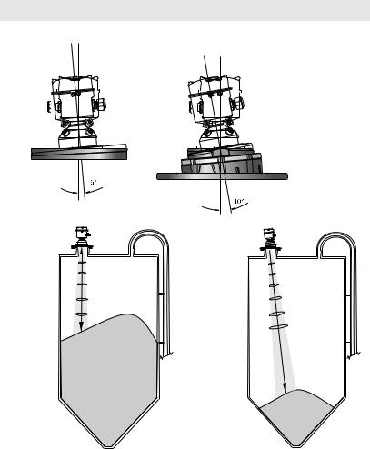
Aimer Adjustment
Note: Aiming will assist in measuring material in the cone.
|
3" flange |
|
4 and 6" flange |
|||||||||||||||||||
|
|
|
|
|
|
|
|
|
|
|
|
|
|
|
|
|
|
|
|
|
|
|
|
|
|
|
|
|
|
|
|
|
|
|
|
|
|
|
|
|
|
|
|
|
|
|
|
|
|
|
|
|
|
|
|
|
|
|
|
|
|
|
|
|
|
|
|
|
|
|
|
|
|
|
|
|
|
|
|
|
|
|
|
|
|
|
|
|
|
|
|
|
|
|
|
|
|
|
|
|
|
|
|
|
|
|
|
|
|
|
|
|
|
|
|
|
|
|
|
|
|
|
|
|
|
|
|
|
|
|
|
|
|
|
|
|
|
|
|
|
|
|
|
|
|
|
|
|
|
|
|
|
|
|
|
|
|
|
|
|
Aiming is not |
Aiming will assist |
Aimer |
|
||
required for signal |
in measuring |
|
optimization with |
material in the |
|
78 GHz frequency. |
cone. |
|
1. |
supplied C spanner, until the LR560 drops down slightly. The enclosure can then be |
Installation |
For 4" and 6" Aimer: Loosen the set screws in the locking ring. |
|
|
|
Holding the electronics enclosure firmly, loosen the Aimer locking ring using the |
|
|
turned freely. |
|
2. |
Direct SITRANS LR560 so the antenna is pointed at an angle perpendicular to the |
|
|
material surface, if possible. |
|
3. |
When the desired position is reached, re-tighten the locking ring using the C |
|
|
spanner, and tighten set screws. |
|
4. |
For the 3" Aimer flange, tapered split washers with pressure rated versions are |
|
|
provided to keep nuts and bolts perpendicular to the flange surface. |
|
7ML19985KB01 |
SITRANS LR560 (mA/HART) – INSTRUCTION MANUAL |
Page 19 |
Installation
Air Purging System
For convenient cleaning, a purging inlet is provided above the antenna. The system provides an 1/8" inlet (female thread) above the antenna where clean, dry air passes to the face of the antenna lens to clean it. The customer will supply the purging air by a manual or automatic valve system.
Notes:
•Purge duration, pressure, and interval, will vary with each application. It is the user’s responsibility to determine the requirements depending on the application and cleaning required.
•Short duration bursts of high pressure provide more effective cleaning than continuous low pressure air.
•It is the customer’s responsibility to ensure that any vacuum or pressure in the measured vessel is maintained, considering the hole that passes through the process connection and SITRANS LR560 antenna system.
Air Consumption (Flow rate versus applied pressure)
Air Pressure (psi) |
Approx. inlet volume flow rate (SCFM) |
20 |
5 |
40 |
10 |
50 |
15 |
80 |
20 |
100 |
25 |
110 |
30 |
Recommended 90 to 110 psi for effective cleaning1)
Purge Connection
•The purge connection is closed by the manufacturer, using a 1/8" plug.
•When the plug is removed to connect a purging system, the operator is responsible for ensuring that the purging circuit conforms to "Ex" requirements: for example, by fitting an NRV valve. 1)
purge process connection with factory-installed 1/8" NPT plug
Purge airflow
•The purge airflow is designed to create a strong vortex of air that rapidly cleans the face of the lens.
•The air purge system can clean both dust and moisture off the lens.
1) Air pressure in vessel can affect purge operation.
Page 20 |
SITRANS LR560 (mA/HART) – INSTRUCTION MANUAL |
7ML19985KB01 |

•It can be used for periodic cleaning.
angled holes direct air flow
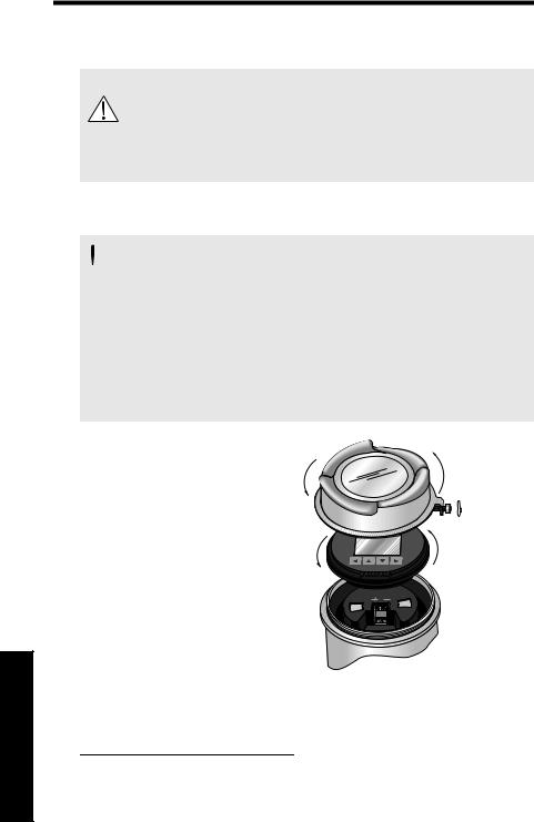
Removable Display
The optional display can be rotated as required, to one of 4 positions, 90 degrees apart. (See Connecting SITRANS LR560 on page 22.)
It can also be used to transfer parameters from one device to another. (See Copy Parameters to Display on page 78.)
Installation
7ML19985KB01 |
SITRANS LR560 (mA/HART) – INSTRUCTION MANUAL |
Page 21 |
Wiring
Power
WARNINGS:
The DC input terminals shall be supplied from a source providing electrical isolation between the input and output, in order to meet
the applicable safety requirements of IEC 61010-1.
 All field wiring must have insulation suitable for rated voltages.
Connecting SITRANS LR560
 WARNINGS:
•Check the device label on your instrument, to verify the approval rating.
•Use appropriate conduit seals to maintain IP or NEMA rating.
•Read Instructions specific to hazardous area installations on page 25.
Notes:
•Use twisted pair cable: AWG 22 to 14 (0.34 mm² to 2.5 mm²).
•Separate cables and conduits may be required to conform to standard instrumentation wiring practices or electrical codes.
1.Loosen locking screw.
2. Remove LR560 lid.
3. Remove optional display by gently turning the display a quarter turn counter-clockwise until it is free.
4.Strip the cable jacket for
approximately 70 mm (2.75") from the end of the cable, and thread the wires through the gland1).
2)
1)
3) ¼ turn
Wiring
1)If cable is routed through conduit, use only approved suitable-size hubs for waterproof applications.
Page 22 |
SITRANS LR560 (mA/HART) – INSTRUCTION MANUAL |
7ML19985KB01 |

5.Connect the wires to the terminals as shown: the polarity is identified on the terminal block.
cable shield
cable gland
(or NPT cable entry)
instrument shield connection
6.Ground the instrument according to local regulations.
7.Tighten the gland to form a good seal.
8.Replace optional display and device lid.
9.Tighten locking screw.
Connecting HART
Typical PLC/mA configuration with HART
active PLC
 R= 250 Ω2) power supply1)


HART modem
|
HART |
SITRANS LR560 |
communicator |
|
|
|
|
|
|
|
Wiring |
|
1) |
PLC, or integral to it. |
|
|
||||
Depending on the system design, the power supply may be separate from the |
|
|
|
||||
2) |
HART resistance (total loop resistance, that is, cable resistance plus 250 Ohm |
|
|
|
|||
|
|
[resistor]) must be less than 550 Ohm for the device to function properly. |
|
|
|
||
|
|
|
|
|
|
|
|
7ML19985KB01 |
SITRANS LR560 (mA/HART) – INSTRUCTION MANUAL |
Page 23 |
|
||||
|
|||||||
Wiring setups for hazardous area installations
The following wiring options are available for hazardous area installations:
•Non-Sparking/Energy Limited wiring (Europe) and Dust Ignition Proof wiring (Europe/International) on page 24
•Non-incendive and Dust Ignition Proof wiring (US/Canada) on page 24
In all cases, check the device label on your instrument, and confirm the approval rating.
1.Non-Sparking/Energy Limited wiring (Europe) and Dust Ignition Proof wiring (Europe/International)
The ATEX certificate listed on the device label can be downloaded from the product page of our website at: www.siemens.com/sitransLR560.
The IECEx certificate listed on the device label can be viewed on the IECEx website. Go to: http://iecex.iec.ch and click on Ex Equipment Certificates of Conformity then enter the certificate numbers IECEx Sira 09ATEX9356X and Sira 09ATEX4357X.
•For power demands, see Loop power on page 132.
•For wiring requirements follow local regulations.
•See also Instructions specific to hazardous area installations on page 25 and the ATEX certificate listed above.
2.Non-incendive and Dust Ignition Proof wiring (US/ Canada)
FM/CSA Class 1, Div 2 connection drawing number A5E02795836 can be downloaded from the product page of our website at: www.siemens.com/sitransLR560.
For power demands, see Temperature derating curve on page 131.
Wiring
Page 24 |
SITRANS LR560 (mA/HART) – INSTRUCTION MANUAL |
7ML19985KB01 |
Loading...