


ST318436LW
Table of contents
 Loading...
seagate ST318436LW, ST318436LC, ST318436LWV, ST318436LCV, ST318426LW Product Manual
...
. . . . . . . . . . . . . . . . . . . . . . . . . . . . . . . . . . . . . . . . . . . . . . . . .
Barracuda 18XL Family:
. . . . . . . . . . . . . . . . . . . . . . . . . . . . . . . . . . . . . . . . . . . . . . . . .
ST318436LW/LC/LWV/LCV
. . . . . . . . . . . . . . . . . . . . . . . . . . . . . . . . . . . . . . . . . . . . . . . . .
ST318426LW/LC, ST3184 16N/W
. . . . . . . . . . . . . . . . . . . . . . . . . . . . . . . . . . . . . . . . . . . . . . . . .
ST39236LW/LC/LWV/LCV
. . . . . . . . . . . . . . . . . . . . . . . . . . . . . . . . . . . . . . . . . . . . . . . . .
ST39226LW/LC, ST39216N/W
. . . . . . . . . . . . . . . . . . . . . . . . . . . . . . . . . . . . . . . . . . . . . . . . .
. . . . . . . . . . . . . . . . . . . . . . . . . . . . . . . . . . . . . . . . . . . . . . . . .
Product Manual, Volume 1
. . . . . . . . . . . . . . . . . . . . . . . . . . . . . . . . . . . . . . . . . . . . . . . . .


. . . . . . . . . . . . . . . . . . . . . . . . . . . . . . . . . . . . . . . . . . . . . . . . .
Barracuda 18XL Family:
. . . . . . . . . . . . . . . . . . . . . . . . . . . . . . . . . . . . . . . . . . . . . . . . .
ST318436LW/LC/LWV/LCV
. . . . . . . . . . . . . . . . . . . . . . . . . . . . . . . . . . . . . . . . . . . . . . . . .
ST318426LW/LC, ST3184 16N/W
. . . . . . . . . . . . . . . . . . . . . . . . . . . . . . . . . . . . . . . . . . . . . . . . .
ST39236LW/LC/LWV/LCV
. . . . . . . . . . . . . . . . . . . . . . . . . . . . . . . . . . . . . . . . . . . . . . . . .
ST39226LW/LC, ST39216N/W
. . . . . . . . . . . . . . . . . . . . . . . . . . . . . . . . . . . . . . . . . . . . . . . . .
. . . . . . . . . . . . . . . . . . . . . . . . . . . . . . . . . . . . . . . . . . . . . . . . .
Product Manual, Volume 1
. . . . . . . . . . . . . . . . . . . . . . . . . . . . . . . . . . . . . . . . . . . . . . . . .

© 1999, 2000 Seagate Technology, LLC All rights reserved
Publication number: 77767535, Rev. B
September 2000
Seagate, Seagate Technology, and the Seagate logo are registered trademarks of Seagate Technology, LLC.
Barracuda, SeaFAX, SeaFONE, SeaBOARD, and SeaTDD are either trademar ks or registe red trademarks of
Seagate Te chnology, LLC, or one of its subsidiaries. Al l other trademarks or registered trademar ks are the
property of their respective owners.
Seagate reserves the right to change, without notice, product offerings or specifications. No part of this publica-
tion may be reproduced in any form without written permission of Seagate Technology, LLC.

Revision status summary sheet
Revision Date Writer/Engineer Sheets Affected
Rev. A 01/18/2000 D. Ashby/B. Reynolds 1/1, v thru viii, 1-98.
Rev. B 09/12/2000 K. Schweiss/ B. Reynolds front cover, ii, 1, 5, 7, 9-10, 31-33, 60,
64-65, 78, 85-87, and backcover.
Notice.
Product Manual 77767535 is Volume 1 of a two volume document with the SCSI Interface information in
the Volume 2 SCSI Interface Product Manual, part number 75789509.
If the SCSI Interface information is needed the Volume 2 Interface Manual should be ordered,
part number 75789509.


Barracuda 18XL Product Manual, Rev. B v
Table of Contents
1.0 Scope . . . . . . . . . . . . . . . . . . . . . . . . . . . . . . . . . . . . . . . . . . . . . . . . . . . . . . . . . . . . . . . . . . . . . . . . . . 1
2.0 Applicable standards and reference documentation. . . . . . . . . . . . . . . . . . . . . . . . . . . . . . . . . . . . 3
2.1 Standards. . . . . . . . . . . . . . . . . . . . . . . . . . . . . . . . . . . . . . . . . . . . . . . . . . . . . . . . . . . . . . . . . 3
2.1.1 Electromagnetic compatibility . . . . . . . . . . . . . . . . . . . . . . . . . . . . . . . . . . . . . . . . . . 3
2.1.2 Electromagnetic susceptibility. . . . . . . . . . . . . . . . . . . . . . . . . . . . . . . . . . . . . . . . . . 3
2.2 Electromagnetic compliance . . . . . . . . . . . . . . . . . . . . . . . . . . . . . . . . . . . . . . . . . . . . . . . . . . 3
2.3 Reference documents . . . . . . . . . . . . . . . . . . . . . . . . . . . . . . . . . . . . . . . . . . . . . . . . . . . . . . . 4
3.0 General description. . . . . . . . . . . . . . . . . . . . . . . . . . . . . . . . . . . . . . . . . . . . . . . . . . . . . . . . . . . . . . . 5
3.1 Standard features. . . . . . . . . . . . . . . . . . . . . . . . . . . . . . . . . . . . . . . . . . . . . . . . . . . . . . . . . . . 7
3.2 Media characteristics . . . . . . . . . . . . . . . . . . . . . . . . . . . . . . . . . . . . . . . . . . . . . . . . . . . . . . . . 7
3.3 Performance. . . . . . . . . . . . . . . . . . . . . . . . . . . . . . . . . . . . . . . . . . . . . . . . . . . . . . . . . . . . . . . 7
3.4 Reliability . . . . . . . . . . . . . . . . . . . . . . . . . . . . . . . . . . . . . . . . . . . . . . . . . . . . . . . . . . . . . . . . . 7
3.5 Unformatted and formatted capacities . . . . . . . . . . . . . . . . . . . . . . . . . . . . . . . . . . . . . . . . . . . 8
3.6 Programmable drive capacity. . . . . . . . . . . . . . . . . . . . . . . . . . . . . . . . . . . . . . . . . . . . . . . . . . 8
3.7 Factory installed accessories . . . . . . . . . . . . . . . . . . . . . . . . . . . . . . . . . . . . . . . . . . . . . . . . . . 8
3.8 Options (factory installed). . . . . . . . . . . . . . . . . . . . . . . . . . . . . . . . . . . . . . . . . . . . . . . . . . . . . 8
3.9 Accessories (user installed) . . . . . . . . . . . . . . . . . . . . . . . . . . . . . . . . . . . . . . . . . . . . . . . . . . . 8
4.0 Performance characteristics . . . . . . . . . . . . . . . . . . . . . . . . . . . . . . . . . . . . . . . . . . . . . . . . . . . . . . . 9
4.1 Internal drive characteristics (transparent to user). . . . . . . . . . . . . . . . . . . . . . . . . . . . . . . . . . 9
4.2 SCSI performance characteristics (visible to user) . . . . . . . . . . . . . . . . . . . . . . . . . . . . . . . . . 9
4.2.1 Access time . . . . . . . . . . . . . . . . . . . . . . . . . . . . . . . . . . . . . . . . . . . . . . . . . . . . . . . 9
4.2.2 Format command execution time (minutes) . . . . . . . . . . . . . . . . . . . . . . . . . . . . . . . 9
4.2.3 Generalized performance characteristics . . . . . . . . . . . . . . . . . . . . . . . . . . . . . . . . . 9
4.3 Start/stop time . . . . . . . . . . . . . . . . . . . . . . . . . . . . . . . . . . . . . . . . . . . . . . . . . . . . . . . . . . . . 11
4.4 Prefetch/multi-segmented cache control . . . . . . . . . . . . . . . . . . . . . . . . . . . . . . . . . . . . . . . . 11
4.5 Cache operation. . . . . . . . . . . . . . . . . . . . . . . . . . . . . . . . . . . . . . . . . . . . . . . . . . . . . . . . . . . 11
4.5.1 Caching write data . . . . . . . . . . . . . . . . . . . . . . . . . . . . . . . . . . . . . . . . . . . . . . . . . 12
4.5.2 Prefetch operation . . . . . . . . . . . . . . . . . . . . . . . . . . . . . . . . . . . . . . . . . . . . . . . . . 12
4.5.3 Optimizing cache performance for desktop and server applications . . . . . . . . . . . 12
5.0 Reliability specifications . . . . . . . . . . . . . . . . . . . . . . . . . . . . . . . . . . . . . . . . . . . . . . . . . . . . . . . . . 15
5.1 Error rates . . . . . . . . . . . . . . . . . . . . . . . . . . . . . . . . . . . . . . . . . . . . . . . . . . . . . . . . . . . . . . . 15
5.1.1 Environmental interference. . . . . . . . . . . . . . . . . . . . . . . . . . . . . . . . . . . . . . . . . . . 15
5.1.2 Read errors. . . . . . . . . . . . . . . . . . . . . . . . . . . . . . . . . . . . . . . . . . . . . . . . . . . . . . . 15
5.1.3 Write errors. . . . . . . . . . . . . . . . . . . . . . . . . . . . . . . . . . . . . . . . . . . . . . . . . . . . . . . 15
5.1.4 Seek errors . . . . . . . . . . . . . . . . . . . . . . . . . . . . . . . . . . . . . . . . . . . . . . . . . . . . . . . 16
5.2 Reliability and service. . . . . . . . . . . . . . . . . . . . . . . . . . . . . . . . . . . . . . . . . . . . . . . . . . . . . . . 16
5.2.1 Mean time between failure . . . . . . . . . . . . . . . . . . . . . . . . . . . . . . . . . . . . . . . . . . . 16
5.2.2 Preventive maintenance . . . . . . . . . . . . . . . . . . . . . . . . . . . . . . . . . . . . . . . . . . . . . 16
5.2.3 Service life . . . . . . . . . . . . . . . . . . . . . . . . . . . . . . . . . . . . . . . . . . . . . . . . . . . . . . . 16
5.2.4 Service philosophy . . . . . . . . . . . . . . . . . . . . . . . . . . . . . . . . . . . . . . . . . . . . . . . . . 16
5.2.5 Service tools . . . . . . . . . . . . . . . . . . . . . . . . . . . . . . . . . . . . . . . . . . . . . . . . . . . . . . 16
5.2.6 Hot plugging Barracuda 18XL disc drives. . . . . . . . . . . . . . . . . . . . . . . . . . . . . . . . 17
5.2.7 S.M.A.R.T. . . . . . . . . . . . . . . . . . . . . . . . . . . . . . . . . . . . . . . . . . . . . . . . . . . . . . . . 17
5.2.8 Drive Self Test (DST) . . . . . . . . . . . . . . . . . . . . . . . . . . . . . . . . . . . . . . . . . . . . . . . 18
5.2.9 Product warranty. . . . . . . . . . . . . . . . . . . . . . . . . . . . . . . . . . . . . . . . . . . . . . . . . . . 21
6.0 Physical/electrical specifications . . . . . . . . . . . . . . . . . . . . . . . . . . . . . . . . . . . . . . . . . . . . . . . . . . 23
6.1 AC power requirements . . . . . . . . . . . . . . . . . . . . . . . . . . . . . . . . . . . . . . . . . . . . . . . . . . . . . 23
6.2 DC power requirements . . . . . . . . . . . . . . . . . . . . . . . . . . . . . . . . . . . . . . . . . . . . . . . . . . . . . 23
6.2.1 Conducted noise immunity . . . . . . . . . . . . . . . . . . . . . . . . . . . . . . . . . . . . . . . . . . . 24
6.2.2 Power sequencing . . . . . . . . . . . . . . . . . . . . . . . . . . . . . . . . . . . . . . . . . . . . . . . . . 24
6.2.3 Current profile. . . . . . . . . . . . . . . . . . . . . . . . . . . . . . . . . . . . . . . . . . . . . . . . . . . . . 25
6.3 Power dissipation . . . . . . . . . . . . . . . . . . . . . . . . . . . . . . . . . . . . . . . . . . . . . . . . . . . . . . . . . . 27
6.4 Environmental limits. . . . . . . . . . . . . . . . . . . . . . . . . . . . . . . . . . . . . . . . . . . . . . . . . . . . . . . . 28

vi Barracuda 18XL Product Manual, Rev. B
6.4.1 Temperature . . . . . . . . . . . . . . . . . . . . . . . . . . . . . . . . . . . . . . . . . . . . . . . . . . . . . .28
6.4.2 Relative humidity . . . . . . . . . . . . . . . . . . . . . . . . . . . . . . . . . . . . . . . . . . . . . . . . . . .30
6.4.3 Effective altitude (sea level). . . . . . . . . . . . . . . . . . . . . . . . . . . . . . . . . . . . . . . . . . .30
6.4.4 Shock and vibration . . . . . . . . . . . . . . . . . . . . . . . . . . . . . . . . . . . . . . . . . . . . . . . . .30
6.4.5 Air cleanliness . . . . . . . . . . . . . . . . . . . . . . . . . . . . . . . . . . . . . . . . . . . . . . . . . . . . .32
6.4.6 Acoustics . . . . . . . . . . . . . . . . . . . . . . . . . . . . . . . . . . . . . . . . . . . . . . . . . . . . . . . . .32
6.4.7 Electromagnetic susceptibility . . . . . . . . . . . . . . . . . . . . . . . . . . . . . . . . . . . . . . . . .32
6.5 Mechanical specifications . . . . . . . . . . . . . . . . . . . . . . . . . . . . . . . . . . . . . . . . . . . . . . . . . . . .33
7.0 Defect and error management . . . . . . . . . . . . . . . . . . . . . . . . . . . . . . . . . . . . . . . . . . . . . . . . . . . . .37
7.1 Drive internal defects. . . . . . . . . . . . . . . . . . . . . . . . . . . . . . . . . . . . . . . . . . . . . . . . . . . . . . . .37
7.2 Drive error recovery procedures . . . . . . . . . . . . . . . . . . . . . . . . . . . . . . . . . . . . . . . . . . . . . . .37
7.3 SCSI systems errors . . . . . . . . . . . . . . . . . . . . . . . . . . . . . . . . . . . . . . . . . . . . . . . . . . . . . . . .38
8.0 Installation . . . . . . . . . . . . . . . . . . . . . . . . . . . . . . . . . . . . . . . . . . . . . . . . . . . . . . . . . . . . . . . . . . . . .39
8.1 Drive ID/option select header . . . . . . . . . . . . . . . . . . . . . . . . . . . . . . . . . . . . . . . . . . . . . . . . .39
8.1.1 Function description. . . . . . . . . . . . . . . . . . . . . . . . . . . . . . . . . . . . . . . . . . . . . . . . .44
8.2 Drive orientation . . . . . . . . . . . . . . . . . . . . . . . . . . . . . . . . . . . . . . . . . . . . . . . . . . . . . . . . . . .45
8.3 Cooling . . . . . . . . . . . . . . . . . . . . . . . . . . . . . . . . . . . . . . . . . . . . . . . . . . . . . . . . . . . . . . . . . .45
8.3.1 Air flow. . . . . . . . . . . . . . . . . . . . . . . . . . . . . . . . . . . . . . . . . . . . . . . . . . . . . . . . . . .45
8.4 Drive mounting . . . . . . . . . . . . . . . . . . . . . . . . . . . . . . . . . . . . . . . . . . . . . . . . . . . . . . . . . . . .46
8.5 Grounding . . . . . . . . . . . . . . . . . . . . . . . . . . . . . . . . . . . . . . . . . . . . . . . . . . . . . . . . . . . . . . . .46
9.0 Interface requirements. . . . . . . . . . . . . . . . . . . . . . . . . . . . . . . . . . . . . . . . . . . . . . . . . . . . . . . . . . . .47
9.1 General description . . . . . . . . . . . . . . . . . . . . . . . . . . . . . . . . . . . . . . . . . . . . . . . . . . . . . . . . .47
9.2 SCSI interface messages supported. . . . . . . . . . . . . . . . . . . . . . . . . . . . . . . . . . . . . . . . . . . .47
9.3 SCSI interface commands supported . . . . . . . . . . . . . . . . . . . . . . . . . . . . . . . . . . . . . . . . . . .48
9.3.1 Inquiry Vital Product data. . . . . . . . . . . . . . . . . . . . . . . . . . . . . . . . . . . . . . . . . . . . .52
9.3.2 Mode Sense data. . . . . . . . . . . . . . . . . . . . . . . . . . . . . . . . . . . . . . . . . . . . . . . . . . .53
9.4 SCSI bus conditions and miscellaneous features supported . . . . . . . . . . . . . . . . . . . . . . . . .61
9.5 Synchronous data transfer . . . . . . . . . . . . . . . . . . . . . . . . . . . . . . . . . . . . . . . . . . . . . . . . . . .63
9.5.1 Synchronous data transfer periods supported. . . . . . . . . . . . . . . . . . . . . . . . . . . . .63
9.5.2 REQ/ACK offset. . . . . . . . . . . . . . . . . . . . . . . . . . . . . . . . . . . . . . . . . . . . . . . . . . . .63
9.6 Physical interface . . . . . . . . . . . . . . . . . . . . . . . . . . . . . . . . . . . . . . . . . . . . . . . . . . . . . . . . . .63
9.6.1 DC cable and connector . . . . . . . . . . . . . . . . . . . . . . . . . . . . . . . . . . . . . . . . . . . . .63
9.6.2 SCSI interface physical description . . . . . . . . . . . . . . . . . . . . . . . . . . . . . . . . . . . . .66
9.6.3 SCSI interface cable requirements . . . . . . . . . . . . . . . . . . . . . . . . . . . . . . . . . . . . .67
9.6.4 Mating connectors . . . . . . . . . . . . . . . . . . . . . . . . . . . . . . . . . . . . . . . . . . . . . . . . . .67
9.7 Electrical description . . . . . . . . . . . . . . . . . . . . . . . . . . . . . . . . . . . . . . . . . . . . . . . . . . . . . . . .81
9.7.1 Single-ended drivers/receivers . . . . . . . . . . . . . . . . . . . . . . . . . . . . . . . . . . . . . . . .81
9.7.2 Multimode—SE or LVD alternative . . . . . . . . . . . . . . . . . . . . . . . . . . . . . . . . . . . . .82
9.8 Terminator requirements. . . . . . . . . . . . . . . . . . . . . . . . . . . . . . . . . . . . . . . . . . . . . . . . . . . . .84
9.9 Terminator power . . . . . . . . . . . . . . . . . . . . . . . . . . . . . . . . . . . . . . . . . . . . . . . . . . . . . . . . . .84
9.10 Disc drive SCSI timing. . . . . . . . . . . . . . . . . . . . . . . . . . . . . . . . . . . . . . . . . . . . . . . . . . . . . . .85
10.0 Seagate Technology support services. . . . . . . . . . . . . . . . . . . . . . . . . . . . . . . . . . . . . . . . . . . . . . .8 7

Barracuda 18XL Product Manual, Rev. B vii
List of Figures
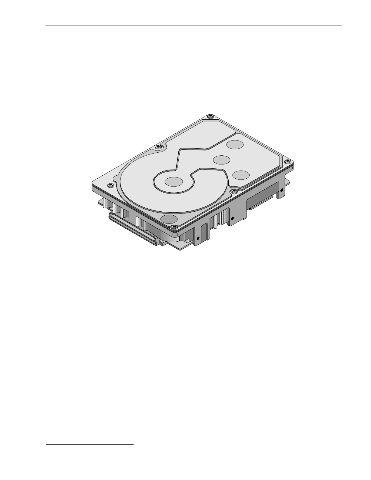
Figure 1. Barracuda 18XL family drive (model “LC” version with 80-pin SCSI I/O connector shown). . . 1
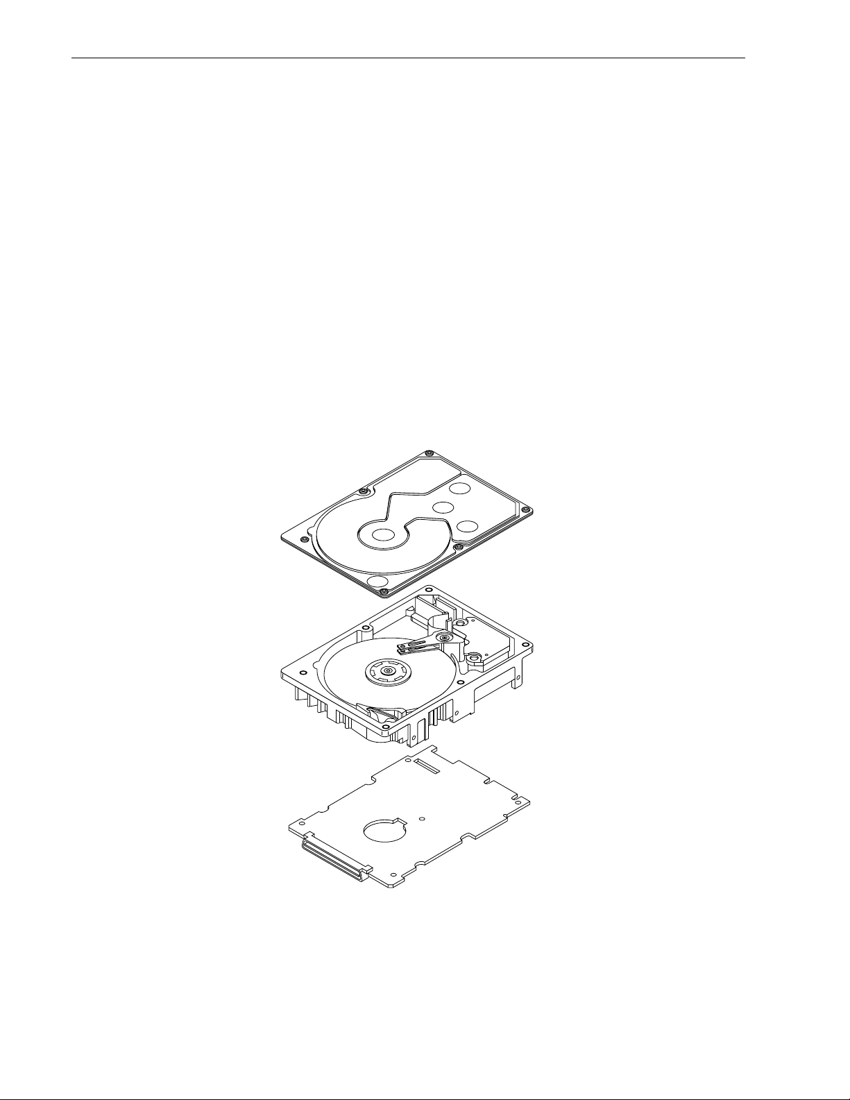
Figure 2. Barracuda 18XL family drive . . . . . . . . . . . . . . . . . . . . . . . . . . . . . . . . . . . . . . . . . . . . . . . . . . 6
Figure 3a. Typical Barracuda 18XL family drive +12 V current profile . . . . . . . . . . . . . . . . . . . . . . . . . . 25
Figure 3b. Typical Barracuda 18XL family drive +5 V current profile . . . . . . . . . . . . . . . . . . . . . . . . . . . 26
Figure 3c. DC current and power vs. input/output operations per second for ST318436
drives (LVD only) . . . . . . . . . . . . . . . . . . . . . . . . . . . . . . . . . . . . . . . . . . . . . . . . . . . . . . . . . . 27
Figure 3d. DC current and power vs. input/output operations per second for ST39236 drives
(SE only). . . . . . . . . . . . . . . . . . . . . . . . . . . . . . . . . . . . . . . . . . . . . . . . . . . . . . . . . . . . . . . . . 27
Figure 4. Locations of PCBA components listed in Table 3 . . . . . . . . . . . . . . . . . . . . . . . . . . . . . . . . . 29
Figure 5. Recommended mounting . . . . . . . . . . . . . . . . . . . . . . . . . . . . . . . . . . . . . . . . . . . . . . . . . . . . 31
Figure 6a. Mounting configuration dim ens io ns for “W,” “LW,” and “LWV” model . . . . . . . . . . . . . . . . . . 33
Figure 6b. Mounting configuration dim ens io ns for “LC” and “LCV” model . . . . . . . . . . . . . . . . . . . . . . . 34
Figure 6c. Mounti ng con fig ur ati on dim ens io ns for “N” models . . . . . . . . . . . . . . . . . . . . . . . . . . . . . . . . 35
Figure 7a. Barracuda 18XL family drive ID select (W/LW/LC/LWV/LCV models). . . . . . . . . . . . . . . . . . 40
Figure 7b. Barracuda 18XL family drive ID select header J6 for N model (J6 Pins 1–12) . . . . . . . . . . . 41
Figure 7c. Barracuda 18XL family drive ID select header J5 for W/LW/LWV models (J5 Pins 1–12). . . 42
Figure 7d. Barracuda 18XL family drive option select header (for LW/LC/LWV/LCV models) . . . . . . . . 43
Figure 7e. Barracuda 18XL family drive option select header (for N and W models) . . . . . . . . . . . . . . . 43
Figure 8. Air flow (suggested) . . . . . . . . . . . . . . . . . . . . . . . . . . . . . . . . . . . . . . . . . . . . . . . . . . . . . . . . 45
Figure 9a. Model “LW” and “LWV” drive physical interface (68 pin J1 SCSI I/O connector). . . . . . . . . . 64
Figure 9b. Model “LC” and “LCV” drive physical interface (80 pin J1 SCSI I/O connector and
DC power connector) . . . . . . . . . . . . . . . . . . . . . . . . . . . . . . . . . . . . . . . . . . . . . . . . . . . . . . . 64
Figure 9c. Models “N” and “W” drive physical interface . . . . . . . . . . . . . . . . . . . . . . . . . . . . . . . . . . . . . 65
Figure 10a. SCSI daisy chain interface cabling for “LW” model drives . . . . . . . . . . . . . . . . . . . . . . . . . . . 69
Figure 10b. SCSI daisy-chain interface cabling for “N” and “W” model drives . . . . . . . . . . . . . . . . . . . . . 70
Figure 11a. Nonshielded 68-pin SCSI device connector used on “LW” models . . . . . . . . . . . . . . . . . . . . 71
Figure 11b. Nonshielded 80 pin SCSI “SCA-2” connector, used on “LC” models. . . . . . . . . . . . . . . . . . . 72
Figure 11c. Nonshielded 50-pin connector for “N” and “W” models . . . . . . . . . . . . . . . . . . . . . . . . . . . . . 73
Figure 12. Single-ended transmitters and receivers on “N” and “W” models . . . . . . . . . . . . . . . . . . . . . 81
Figure 13. LVD steady-state output voltage test circuit (T10/1302D, Annex A, Figure 1). . . . . . . . . . . . 83
Figure 14. Typical SE-LVD alternative transmitter receiver circuits . . . . . . . . . . . . . . . . . . . . . . . . . . . . 83

Barracuda 18XL Product Manual, Rev. B 1
1.0 Scope
This manual describes the Seagate Technology®, LLC. Barracuda 18XL™ disc dri ves.
Barracuda 18XL dr ives suppor t the small compu ter system interface (SCSI) as described in the ANSI SCSI,
SCSI-2, and SCSI-3 (Fast-20, Fast-40, and Fast-80) interface specifications to the extent described in this
manual.* Ultra, Ultra2, and Ultra160 are the names Seagate calls these interfaces. The SCSI Interfac e P r odu ct
Manual (pa r t number 75 789509) d escri bes gene ral SCSI i nterface character istic s of this and other families of
Seagate drives.
From this point on in this product manual th e reference to Bar racuda 18X L mode ls is re ferred to as “the dr ive”
(unless references to individual models are necessary).
Figure 1. Barracuda 18XL family drive (model “LC” version with 80-pin SCSI I/O connector shown)
*The ANSI specifications have now replaced the terms “SCSI,” “SCSI-2,” and “SCSI-3” with “SCSI.”

2 Barracuda 18XL Product Manual, Rev. B

Barracuda 18XL Product Manual, Rev. B 3
2.0 Applicable standards and reference documentation
The drive has been developed as a system peripheral to the highest standards of design and construction. The
drive depends upon i ts host equip ment to provide adequ ate power and environment i n order to achieve optimum performance and compli ance with applicable industry and governm ental regulations. Special attention
must be given in the areas of safety, power distribution, shielding, audible noise control, and temperature regulation. In particular, the drive must be securely mounted in orde r to guara ntee the s pec if ied per formance characteristics. Mounting by bottom holes must meet the requirements of Section 8.4.
2.1 Standards
The Barracuda 18XL family complies with Seagate standards as noted in the appropriate sections of this Manual and the Seagate SCSI Interface Product Manual, part number 75789509 (Vol. 2).
The Barracuda 18XL d isc dri ve is a UL r ecogn ized co mponen t per UL1950 , CSA certified to CA N/CSA C22.2
No. 950-95, and VDE certified to VDE 0805 and EN60950.
2.1.1 Electromagnetic compatibility
The drive, as delivered, is designed for system integration and installation into a suitable enclosure prior to use.
As such the drive is suppli ed as a subassembly and is not su bject to Subpar t B of Part 15 of the FCC Rules
and Regulations nor the Radio Interference Regulations of the Canadian Department of Communications.
The design characteristics of the drive serve to minimize radiation when installed in an enclosure that provides
reasonable shielding. As such, the drive is capable of meeting the Class B limits of the FCC Rules and Regulations of the Canadian Department of Communications when properly packaged. However, it is the user’s
responsibility to assure that the drive meets the appropriate EMI req uirements in their syst em. Shielded I/O
cables may be required if the e nclosure does not provide ad equate sh ielding. If the I/O c ables are externa l to
the enclosure, shielded cables should be used, with the shields grounded to the enclosure and to the host controller.
2.1.2 Electromagnetic susceptibility
As a component assembly, the drive is not required to meet any susceptibility per formance requ irements. It is
the responsibility of tho se integrating the dr ive within their sy stem s to perform thos e tests req uired and design
their system to ensu re that equipment operating in the sam e system as the drive or external to the s ystem
does not adversely affect the performance of the drive. See also Section 5.1.1 and Table 2, DC power requirements.
2.2 Electromagnetic compliance
Seagate uses an independ ent laboratory to co nfirm compliance to the directives/standard(s) for CE Mark ing
and C-Tick Marking. The drive was tested in a representative system for typical applications. The selected system represents the most popular characteristics for test platforms. The system configurations include:
• Typical current use microprocessor
• 3.5-inch floppy disc drive
• Keyboard
• Monitor/display
• Printer
• External modem
• Mouse
Although the test system wi th this Seag ate mode l co mpl ie s to the dire cti ves/standa rd(s ), we cann ot gua rante e
that all systems will comply. The computer manufacturer or system i ntegrator shall confir m EMC complianc e
and provide CE Marking and C-Tick Marking for their product.
Electromagnetic compliance for the European Union
If this model has the CE Marki ng it complies with the European Union requirem ents of the Electromagnetic
Compatibility Direc tive 89/336/EEC o f 03 May 1989 as ame nded by Direct ive 92/31/EE C of 28 Ap r il 1992 an d
Directive 93/68/EEC of 22 July 1993.

4 Barracuda 18XL Product Manual, Rev. B
Australian C-Tick
If this model has the C-Tick Markin g it complies with the Australia/New Zea land Standard A S/NZS3548 199 5
and meets the Electro magnetic Compatibility (EMC) Framework requirements of Australia’s Spectrum Management Agency (SMA).
2.3 Reference documents
Barracuda 18XL Installation Guide (for LW/LC/LWV/LCV) Seagate P/N 75789511
Safety and Regulatory Agency Spec ifi cation Seagate P/N 75789512
SCSI Interface Product Manual Seagate P/N 75789509
ANSI small computer system interface (SCSI) document numbers:
X3.131-1994 SCSI-2
T10/1302D SPI-3
X3T10/1143D EPI
T10/1236D SPC-2
T10/999D SBC
T10/1157D SAM-2
SFF-8046 Specification for 80-pin connector for SCSI disk drives
SCA-2 EIA Specification ANSI/EIA
Package Test Specification Seagate P/N 30190-001 (under 100 lb.)
Package Test Specification Seagate P/N 30191-001 (over 100 lb.)
Specification, Acoustic Test Requirements, and Procedures Seagate P/N 30553-001
In case of conflict between this document and any referenced document, this document takes precedence.

Barracuda 18XL Product Manual, Rev. B 5
3.0 General description
Barracuda 18XL drives combine magnetoresistive (GMR) heads, partial response/maximum likelihood (PRML)
read channel elec tro ni cs, em bed ded s ervo technology, an d a SCSI-3 (Fast-20, Fast 40, and Fast-80) interface
to provide high performance, high capacity data storage for a variety of systems including engineering workstations, network servers, mainframes, and supercomputers.
Fast-20, Fast-40, and Fast-80 (also known as Ultra SCS I, Ultra-2 SCS I, and Ultra160 SCSI, res pectively) are
negotiated transfer rates. These transfer rates will occur only if your host adapter also suppor ts these data
transfer rates. This drive also operates at SCSI-1 and SCS I-2 data transfer rates for backward compatibility
with non-Fast-20/Fast-40/Fast-80 capable SCSI host adapters.
Note.
ST318426LW/LC and ST39226LW/LC models do not support Fast-80/Ultra160.
Table 1 lists the features that differentiate the various Barracuda 18XL models.
Table 1: Drive model number vs. differentiating features
Model number
Number
of heads I/O circuit type [1]
Number of I/O
connector pins
Number of I/O
data bus bits
Data buffer
size
ST318436LW 6 multimode (SE/LVD) 68 16 2 MB
ST318436LC 6 multimode (SE/LVD) 80 16 2 MB
ST318436LWV 6 multimode (SE/LVD) 68 16 4 MB
ST318436LCV 6 multimode (SE/LVD) 80 16 4 MB
ST318426LW 6 multimode (SE/LVD) 68 16 1 MB [2]
ST318426LC 6 multimode (SE/LVD) 80 16 1 MB [2]
ST318416N 6 single-ended 50 8 2 MB
ST318416W 6 single-ended 68 16 2 MB
ST39236LW 3 multimode (SE/LVD) 68 16 2 MB
ST39236LC 3 multimode (SE/LVD) 80 16 2 MB
ST39236LWV 3 multimode (SE/LVD) 68 16 4 MB
ST39236LCV 3 multimode (SE/LVD) 80 16 4 MB
ST39226LW 3 multimode (SE/LVD) 68 16 1 MB [2]
ST39226LC 3 multimode (SE/LVD) 80 16 1 MB [2]
ST39216N 3 single-ended 50 8 2 MB
ST39216W 3 single-ended 68 16 2 MB
[1] See Section 9.6 for details and definitions.
[2] Fast-80/Ultra160 mode not supported by this model.
The drive records and recovers data on 3.0-inch (74 mm) non-removeable discs.
The drive suppor ts the Small Comp uter System Inter face (SCSI) as described in the ANSI SCSI S PI-3 inter-
face specifications to the extent des cribed in thi s manual (volume 1), whic h defines the prod uct performance
characteristics of the Barracuda 18XL family of drives, and the SCSI Interface Product Manual (volume 2), part
number 75789509, which de scribes the general interface charac teristic s of this and other families of Seagate
SCSI drives.
6 Barracuda 18XL Product Manual, Rev. B
The drive’s interface supports multiple initiators, disconnect/reconnect, self-configuring host software, and
automatic features that relieve the host from the necessity of knowing the physical characteristics of the targets
(logical block addressing is used).
The head and disc assembly (HDA) is sealed at the factory. Air circulates within the HDA through a nonreplaceable filter to maintain a contamination-free HDA environment.
Refer to Figure 2 for an exploded view of the drive. This exploded view is for information only—nev er di sass emble the HDA and do not attempt to service items in the se aled e nclos ure (h eads, med ia, actuat or, etc.) as this
requires special facilities. The drive contains no replaceable parts. Opening the HDA voids your warranty.
Barracuda 18XL drives use a dedicated landing zone at the innermost radius of the media to eliminate the possibility of destroying or degrading data by landing in the data zone. The drive automatically goe s to the landing
zone when power is removed.
An automatic shipping lock prevents potential damage to the heads and discs that results from movement during shipping and ha ndl ing . The s hi ppi ng lock automa tic al ly disengages when power is applied to the d rive and
the head load process begins.
Barracuda 18XL dr ives decode track 0 location data f rom the ser vo data embedd ed on each su rface to eliminate mechanical transducer adjustments and related reliability concerns.
A high-performance actuator assembly with a low-inertia, balanced, patented, straigh t-arm design provides
excellent performance with minimal power dissipation.
Figure 2. Barracuda 18XL family drive

Barracuda 18XL Product Manual, Rev. B 7
3.1 Standard features
The Barracuda 18XL family has the following standard features:
• Integrated SCSI controller
• SCSI multimode single-ended or low voltage differential drivers and receivers
• 8 bit or 16 bit I/O data bus models available
• Asynchronous and synchronous data transfer protocol
• Firmware downloadable via SCSI interface
• Selectable sector sizes from 512 to 4,096 bytes/sector in multiples of 2 bytes/sector
• Programmable drive capacity
• Programmable sector reallocation scheme
• Flawed sector reallocation at format time
• Programmable auto write and read reallocation
• Reallocation of defects on command (post format)
• Enhanced ECC correction capability up to 240 bits
• Sealed head and disc assembly
• No preventative maintenance or adjustment required
• Dedicated laser textured head landing zone
• Embedded servo data rather than a separate servo data surface
• Self diagnostics performed when power is applied to the drive
• 1:1 Interleave
• Zoned bit recording (ZBR)
• Vertical, horizontal, or top down mounting
• Dynamic spindle brake
• 2 MByte data buffer standard (1 Mbyte on some drives, see Table 1) or 4 Mbyte optional
• Hot plug compatibility
• Low audible noise for office environment
• Low power consumption
3.2 Media characteristics
The media used on the dr ive has a di ameter of a pproximately 3 .0 in ches (7 4 mm). The alumi num substrat e is
coated with a thin film magneti c mat eria l, overcoated with a propr iet ar y prote ctive layer for improved durability
and environmental protection.
3.3 Performance
• Suppor ts i ndu stry standard Fast-20, Fast-40, and Fast-80 SCSI interfaces (also called “Ultra SCSI,” “Ultra-2
SCSI,” and “Ultra160 SCSI,” respectivel y)
Note.
• Programmable multi-segmentable cache buffer (see Section 4.4)
• 7200 RPM spindle. Average latency = 4.17 msec
• Command queuing of up to 64 commands
• Background processing of queue
• Supports start and stop commands (spindle stops spinning)
3.4 Reliability
• 1,200,000 hour MTBF (mature)
• LSI circuitry
• Balanced low mass rotary voice coil actuator
• Incorporates industry-standard Self-Monitoring, Analysis and Reporting Technology (S.M.A.R.T.)
• Incorporates Seek To Improve Reli ab il ity algor i thm (STIR)
• 5-year warranty
ST318426LW/LC and ST39226LW/LC models do not support Fast-80/Ultra160.

8 Barracuda 18XL Product Manual, Rev. B
3.5 Unformatted and formatted capacities
Formatted capacity depends on the number of spare reallocation sectors reserved and the number of bytes per
sector. The following table shows the standar d OEM model rea d capacities da ta. Total LBAs = read c apacity
data (shown below) +1.
Formatted data block size
512 bytes/sector [1] [2]
ST318436 35,885,167 (223906Fh) (18.373 GB)
ST318426 35,885,167 (223906Fh) (18.373 GB)
ST318416 35,885,167 (223906Fh) (18.373 GB)
ST39236 17,942,583 (111C837h) (9.186 GB)
ST39226 17,942,583 (111C837h) (9.186 GB)
ST39216 17,942,583 (111C837h) (9.186 GB)
Notes.
[1] Sector size se lectable at format time. Users having the necessar y equipmen t may modify the data block
size before issuing a format co mmand and obtain different formatted capa cities than those listed. See
Mode Select command and Format command in the SCSI Interface Product Manual, part number
75789509.
[2] User available capacity depends on spa re reallocation scheme se lected. The number of data tracks per
sparing zone and the number of alte rnate sectors (LBAs ) per sparing zone can be deter mined by using
the Mode Sense command and reading Mode Page 03h. Total LBAs(h) x 200(h) = total byte capacity.
3.6 Programmable drive capacity
Using the Mode Select command, the drive can change its capacity to something less than maximum. See the
Mode Select Parameter List table in the SCS I Interface Product Manual, par t number 7578 9509. Refer to the
Parameter list block descriptor number of blocks field. A value of zero in the number of blocks field indic ates
that the drive shall not change the capacity it is curr ently form atted to have. A number in the number of blocks
field that is less than the ma ximum number of L BAs changes the total drive capacity to the value in the block
descriptor number of blocks field. A value of FF FF FF FF in the number of blocks field restores the drive
capacity to the maximum capacity.
3.7 Factory installed accessories
OEM Standard drives are shipped with the Barracuda 18XL Installation Guide, part number 75789511, and the
Safety and Regulatory Agency Specification, part number 75789512, (unless otherwise specified). The factory
also ships with the drive a small bag of jumper plugs used for the J2, J5, and J6 option select jumper headers.
3.8 Options (factory instal led)
All customer request ed options are incorporate d during production or packaged at the manufacturin g facility
before shipping. Some of the options available are (not an exhaustive list of possible options):
• Other capacities can be ordered depending on sparing scheme and sector size requested.
• 4 Mbyte optional buffer size.
• Single unit shipping pack. The drive is norm ally shipped in bulk pa ckaging to provide maximum protec tion
against transit damage. Units shipped individually require additional protection as provided by the single unit
shipping pack. Users planning single unit distribution should specify this option.
• The Barracuda 18XL Installation Guide, part number 75789511, and the Safety and Regulatory Agency
Specification, p art number 75789 512 , ar e i nclu ded with each standard OEM drive shipped, but extra copies
may be ordered.
3.9 Accessories (user installed)
The following accessories are available.
• Single unit shipping pack.

Barracuda 18XL Product Manual, Rev. B 9
4.0 Performance characteristics
4.1 Internal drive characteristics (transparent to user)
ST318436 ST318426 ST318416 ST39236 ST39226 ST39216
Drive capacity 18.373 18.373 18.373 9.186 9.186 9.186 Gbyte (formatted,
rounded off values)
Read/write heads 6 6 6 3 3 3
Bytes/track 213 213 213 213 213 213 Kbytes (average,
rounded off values)
Bytes/surface 3,642 3,642 3,642 3,642 3,642 3,642 Mbytes (unformatted,
rounded off values)
Tracks/surface (total) 14,384 14,384 14,384 14,384 14,384 14,384 Tracks (user accessible)
Tracks/inch 18,145 18,145 18,145 18,145 18,145 18,145 TPI
Peak bits/inch 328 328 328 328 328 328 KBPI
Internal data rate 195-315 195-315 195-315 195-315 195-315 195-315 Mbits/sec (variable
with zone)
Disc rotational speed 7,200 7,200 7,200 7,200 7,200 7,200 r/min ± 0.5%
Average rotational
latency 4.17 4.17 4.17 4.17 4.17 4.17 msec
Recording code 16/17 16/17 16/17 16/17 16/17 16/17 EPR4
4.2 SCSI performance characteristics (visible to user)*
The values given in Section 4.2.1 apply to all models of the Barracuda 18XL family unless otherwise specified.
Refer to Section 9.10 and to the SC SI Interface Product Manual, part number 757895 09, for addition al timing
details.
4.2.1 Access time [8]*
Including controll er o verhe ad (wi thout disc onne ct) [1] [4]
Drive level (18.373 GB models) Drive level (9.186 GB models)
Read Write Read Write
msec msec
Average – Typical [3] 6.0 6.5 6.0 6.5
Single Track – Typical [3] 0.70 0.70 0.70 0.70
Full Stroke – Typical [3] 10.50 11.00 10.50 11.0
4.2.2 Format command execution time (minutes) [1]*
18.373 GB models 9.186 GB models
Maximum (with verify) 30 15
Maximum (no verify) 15 7.5
4.2.3 Generalized performance characteristics
Data buffer transfer rate to/from disc media (one 512-byte sector):
18.373 GB models 9.186 GB models
Min. [4]* 24.7 24.7 MByte/sec
Avg. [4] 32.1 32.1 MByte/sec
Max. [4] 39.4 39.4 MByte/sec
*[ ] All notes for Section 4.2 are listed at end of Section 4.2.3.

10 Barracuda 18XL Product Manual, Rev. B
Data buffer transfer rate to/from disc media: (< 1 track):
18.373 GB models 9.186 GB models
Min. [4] 18.5 18.5 MByte/sec
Avg. [4] 23.9 23.9 MByte/sec
Max. [4] 29.4 29.4 MByte/sec
SCSI interface data transfer rate (asynchronous, 15 bit SCSI bus) [5]:
Maximum instantaneous 5 Mbytes/sec [6]
Maximum average 5 Mbytes/sec [7]
Target sustainable transfer rate:
Average 22
Maximum 25
Minimum 15
Synchronous transfer rate:
16 bit SE I/O data bus models 40 Mbytes/sec (Fast-40 or Ultra-2)
16 bit LVD I/O data bus models 160 Mbytes/sec (Fast-80 or Ultra160) [9]
Sector Sizes:
Default 512 byte user data blocks
Variable 512 to 4,096 bytes per sector in multiples of 2 bytes per sector.
If n (number of bytes per sector requested) is odd, then n–1 sectors will be used.
Read/write consecutive sectors on a track Yes
Flaw reallocation performance impact (for flaws reallocated at format time using
Negligible
the spare sectors per sparing region reallocation scheme)
Command overhead time for head switch in sequential mode
Command overhead time for cylinder switch in sequential mode
Command overhead, sequential read, tagged
Command overhead, sequential W/R, untagged
918 µsec
918 µsec
8 µsec
8 µsec
Average rotational latency 4.17 msec
Notes for Section 4.2.
[1] Execution time measur ed from receipt of the last Byte of the Co mmand Descriptor Block (CDB) to the
request for a Status Byte Tr ansfer to the Initiator (excluding connect/disconnect).
[2] Maximum times are specified over the worst case conditions of te mperature, voltage margins and drive
orientation. W hen co mpar ing spec ified a ccess times, ca re sh ould be taken to dis tingui sh bet ween typic al
access times and maximum acc ess times. The b est compar ison is o btained by syst em benchmar k tests
conducted under identical conditions. Maximum times do not include error recovery.
[3] Typical Access tim es are measu red u nder nomina l con ditio ns of temperatur e, voltage, and hor izonta l or i-
entation as measured on a representative sample of drives.
[4] Assumes no errors and no sector has been relocated.
[5] Rate measured from the start of the first sector transfer to or from the Host.
[6] Assumes system ability to support the rates listed and no cable loss.
[7] Simulated.
[8] Access time = controller overhead + average seek time
Access to data = controller overhead + average seek time + latency time
[9] ST318426LW/LC and ST39226LW/LC models do not support Fast-80/Ultra160.

Barracuda 18XL Product Manual, Rev. B 11
4.3 Start/stop time
After DC power at nominal voltage has been applied, the drive typically becomes ready for media access commands within 15 se conds if the Mot or Start Option is disabled ( i.e. the motor st ar ts as soon as the power has
been applied). Maximum is 25 seconds. If a recoverable error condition is detected dur ing the s tar t s equenc e,
the drive executes a recovery procedure whic h may cause the time to bec ome ready to exceed 15, but to
become ready within 25 seconds. Duri ng spin up to ready time, the drive responds to some comma nds over
the SCSI interface in less than 1.5 second s afte r applic ation of power. Stop time is typicall y <10 se conds from
removal of DC power. Maximum is <20 seconds.
If the Motor Star t Option is en abled, the inter nal con troller acc epts the co mmands li sted in the SCSI Interface
Product Manual le ss than 3 seconds after DC power has been app lied. After the Motor Star t Command has
been received the drive becomes r eady for normal operation s within 13 seconds typically (excluding an error
recovery procedure). The Mo tor Start Comm and can also be used to comm and the drive to stop the spindle
(see SCSI Interface Product Manual, part number 75789509).
There is no power control switch on the drive.
4.4 Prefetch/multi-segmented cache control
The drive provides prefetch (read look-ahead) and multi-segmented cache control algorithms that in many
cases can enhance system performance. “Cache” as used herein refers to the drive buffer storage space when
it is used in “cache” operations. To selec t prefetch and cache features the host sends the Mode Select command with the proper values in the applicable bytes in Mode Page 08h (see SCSI Int erface Product Manual,
part number 75789509). Prefetch and cache operation are independent features from the standpoint that each
is enabled and disabled independently via the Mode Select command. However, in actual operation the
prefetch feature overlaps cache operation somewhat as is noted in Section 4.5.1 and 4.5.2.
All default cache and prefetch Mode pa rameter values (Mode Page 08h) for standard OEM versions of this
drive family are given in Table 9a.
4.5 Cache operation
The buffer can be divided into logical s egments (Mode Se lect Page 08h, byte 13) from whi ch data is read an d
to which data is written. The dri ve mai ntains a ta ble of lo gic al block disk med iu m addre ss es of the data store d
in each segment of t he buffer. If cache operation is enabled (RC D bit = 0 in Mode Page 08h, byte 2, bit 0. See
SCSI Interface Product Manual, pa rt number 75789509 ), da ta r eq ueste d by the ho st wi th a Re ad command is
retrieved from the buffer (if it is there), before any disc access is initiated. If cache operation is not enabled, the
buffer (still segmented with required number of segments) is still used, but only as circular buffer segments during disc medium read op eration s (disreg ardin g Prefetch opera tion for the moment ). Th at is, the dr ive does not
check in the buffer segments for the reque sted read data, but goe s directly to the medium to retr ieve it. The
retrieved data merely passes through some buffer segment on the way to the host. On a cache “miss”, all data
transfers to the host are in accordance with “buffer-full” ratio rules. On a cache “hit” the drive ignores the
“buffer-full” ratio rules. See explanations assoc iated with Mo de pa ge 02h (dis conne ct/re conne ct cont rol) in th e
SCSI Interface Product Manual, part number 75789509.
The following is a simplified description of a read operation with cache operation enabled:
Case A -
1. Drive transfers to the initiator the first LB requested plus all subsequent contiguous LB’s that are alre a dy in
2. When a reque ste d LB is reached that is no t in any cache segm ent, th e dr ive fetches i t and any remai ning
3. If the prefetch feature is enabled, refer to Section 4.5.2 for operation from this point.
A Read command is received and the first logical block (LB) is already in cache:
the cache. This data may be in multiple segments.
requested LBs from the disc an d puts them in a s egment of the cache. The dr ive transfers the remainin g
requested LBs from the ca che to t he host in accorda nce with the disconn ect/r econn ect speci fication mentioned above.
Case B -
1. The drive fetches the reque sted LB’s from the disc and transfers them into a segme nt, and from there to
2. If the prefetch feature is enabled, refer to Section 4.5.2 for operation from this point.
A Read command requests data, the first LB of which is not in any segment of the cache:
the host in accordance with the disconnect/reconnect specification referred to in case A.

12 Barracuda 18XL Product Manual, Rev. B
Each buffer segment is actually a s elf-contained circular storage (wrap-around oc curs), the length of which is
an integer number of disc medium sectors. The wrap-around capability of the individual segments greatly
enhances the buffer’s over all performance as a cache storage, allowing a wide range of user selectable configurations, which includes their use in the prefetch operation (if enabled), even when cache operation is disabled
(see Section 4.5.2). The number of se gments may be sele cted using th e Mode Sel ect comma nd, but the size
can not be direct ly s elec ted. S ize is s elect ed onl y as a by-pro duct of se lecting the segment numb er spec ific ation. The size in Kbytes of each segment is not reported by the Mode Sense command page 08h, bytes 14 and
15. The value 0XFFFF is always reported. If a size specification is sent b y the host in a Mode Select co mmand
(bytes 14 and 15) no new segment size is set up by the d rive, and if the “STRICT” bit in Mode page 00h (byte
2, bit 1) is set to one, the dr ive responds as i t does for any attempt to cha nge unchang eable parameters (se e
SCSI Interface Product Manual, par t number 7578950 9). The drive suppor ts op eration of any integer number
of segments from 1 to 16.
4.5.1 Caching write data
Write caching is a wr ite op eration by the dr ive that makes use of a drive buffer storage area where the data t o
be written to the medium is stored in one or more segments while the drive performs the write command.
The same buffer space and segmentation is used as set up for read functions. The buffer segmentation
scheme is set up or cha nged independently, having nothing to do with the state of RCD. When a write command is issued, if RCD=0, the cache is first checked to see if any logical blocks that are to be written are
already stored in the cac he from a previous read or write comman d. If there are, the respective cache segments are cleared. The new data is cached for subsequent Read commands.
If the number of wri te data lo gical blocks exceeds t he size of t he segme nt being w ritte n into, when the end o f
the segment is reached, the data is written into the beginning of the same cache segment, overwriting the data
that was written there at the beginning of the operation. However, the drive does not overwrite data that has not
yet been written to the medium.
If write caching is enabled (WCE=1), then the drive may return GOOD status on a write command after the
data has been transferred into the cache, but before the data has been written to the medium. If an error occurs
while writing the data to the medium, and GOOD status has already been returned, a deferred error will be
generated. Write commands that have returned GOOD status but still have uncommitted data in the cache are
treated similarly to a normal queued command and therefore occupy a command queue slot. This may temporarily reduce the number of commands that may be queued by the host until the write data has been written to
the medium.
The Synchronize Cache command may be used to force the drive to write all cached write data to the medium.
Upon completion of a Synchronize Cache command, all data received from previous write commands will have
been written to the medium. The Star t/Stop command with the stop bit s et will force a sync cache operat ion
before the drive stops.
Table 9a shows Mode default settings for the drives.
4.5.2 Prefetch operation
If the Prefetch feature is enabled, data in conti guous lo gical blocks on the disc i mmedia tely b eyond that which
was requested by a Read comman d can be retri eved and stored in the buffer for immediate transfer from the
buffer to the host on subsequent Read commands that request those logical blocks (this is true even if “cache”
operation is disabled). Though the pr efetch operation uses the buffer as a “cache”, finding the requested dat a
in the buffer is a prefetch “hit”, not a “cache” operation “hit”. Prefetch is enabled using Mod e Select pa ge 08h,
byte 12, bit 5 (Disable Read Ahe ad - DRA bit). DRA bit = 0 enables prefetch. Since data that is prefetched
replaces data already in some buffer segment(s), the host can lim it the amount of prefetch data to optim ize
system performance. Th e max pre fetch field (bytes 8 and 9) limits th e amount of pr efetch. The dri ve does not
use the prefetch “ceiling” field (bytes 10 and 11).
During a prefetch operation, the dri ve crosses a cyl inder bounda r y to fetch more data o nly if the Discontinuity
(DISC) bit is set to one in bit 4 of byte 2 of Mode parameters page 08h.
4.5.3 Optimizing cache performance for desktop and server applications
Desktop and server applications require different drive caching operations for optimal performance. This
means it is difficult to provide a single configuration that meets both of these needs. In a desktop environment,
Barracuda 18XL Product Manual, Rev. B 13
you want to configure the cache to r espond quickly to repetiti ve accesses of multiple s mall segments of dat a
without taking th e tim e to “lo ok a head” to the next contiguous segments of data. In a ser ver environment, you
want to configure the cac he to provide large volumes of sequential data in a non-repetitive manner. In this
case, the ability of the cache to “look ahead” to the next contigu ous segments of sequent ial data is a good
thing.
The Performance Mode (PM) bit contr ols the way the drive switches the cache buffer into different modes o f
segmentation. In “server mode” (PM bit = 0), the drive can increase the number of cache buffer segments
above the value defined in Mode Page 8, Byte 13, as neede d to o ptim ize the perfor ma nc e, based on the command stream from the host. In “desktop mode” (PM bit = 1), the number of segments is maintained at the value
defined in Mode Page 8, Byte 13, at all times. For additional inform ation about the PM bit, refer to the Unit
Attention Parameters page (00h) of the Mode Sense com ma nd (1 Ah) i n the SCS I In terface Manual, pa rt number 75789509.
The base cache buffer configuration for desktop o r server environments needs to be set co rrectly by the host
system. This involves setting the PM bit in M ode Page 0, Byte 2, as well as the numbe r of cache buffer segments in Mode Page 8, Byte 13. The firm ware default values are set to desktop mode (PM bit = 1), and the
number of cache buffer segments set to 1 6 (10h). The OE M saved values for drives with LW, W, and N interfaces are the same as the firmware default values. For drives with the LC interface, the OEM saved values are
changed to server mod e (PM bit=0), and the number of cache buffer segments are set to 3 (03h) . Refer to
Tables 9a through 9f in S ection 9.3.2 for drive default values for the PM bit in Mode Page 0, Byte 2 and the
number of cache buffer segments in Mode Page 8, Byte 13.
Caching Parameters page (08h)
Byte 13 (Number of Cache Segments)
Desktop mode 10h (16 segments -- default for LW, W, and N models)
Server mode 03h (3 segments -- de fault for LC models)
Unit Attention Parameters page (00h)
Byte 2, Bit 7 (PM bit)
1
0

14 Barracuda 18XL Product Manual, Rev. B

Barracuda 18XL Product Manual, Rev. B 15
5.0 Reliability specifications
The following reliability spe cifications assume correct hos t/drive operational interface, including all interface
timings, power supply voltages, environmental requirements and drive mounting constraints (see Section 8.4).
Seek Errors
Less than 10 in 10
Read Error Rates [1]
Recovered Data Less than 10 errors in 10
Unrecovered Data Less than 1 sector in 10
Miscorrected Data Less than 1 sector in 10
MTBF 1,200,000 hours
Service Life 5 years
Preventive Maintenance None required
Note.
[1] Error rate specified with automatic retries and data correction with ECC enabled and all flaws reallocated.
5.1 Error rates
The error rates stated in this specification assume the following:
• The drive is operated per this specification using DC power as defined in this manual (see Section 6.2).
• The drive has been formatted with the SCSI FORMAT commands.
• Errors caused by media d efects or hos t system failures are exclude d from er ror rate comp utat ions. Refer to
Section 3.2, “Media Characteristics.”
8
seeks
12
bits transferred (OEM default settings)
15
bits transferred (OEM default settings)
21
bits transferred
5.1.1 Environmental interference
When evaluating systems operatio n under condit ions of Ele ctromagnetic Interference (EMI), the performanc e
of the drive within the s ystem shall b e consi dered acce ptable if the dr ive does not g enerate an unre coverable
condition.
An unrecoverable error, or unrecoverable condition, is defined as one that:
• Is not detected and corrected by the drive itself;
• Is not capable of being detected from the error or fault status provided through the drive or SCSI interface; or
• Is not capable of being recovered by normal dr ive or sys tem rec overy pro cedur es wit hou t opera tor inte rven-
tion.
5.1.2 Read errors
Before determination or measurement of read error rates:
• The data that is to be used for measurement of read error rates must be verified as being written correctly on
the media.
• All media defect induced errors must be excluded from error rate calculations.
5.1.3 Write errors
Write errors can occur as a result of media defects, environmental interference, or equipment malfunction.
Therefore, write errors are not predictable as a function of the number of bits passed.
If an unrecoverable write error occurs beca use of a n equipm ent mal functi on in the dr ive, the error is classi fied
as a failure affecting MTBF. Unrecoverable write errors are those which cannot be corrected within two
attempts at writing the record with a read verify after each attempt (excluding media defects).

16 Barracuda 18XL Product Manual, Rev. B
5.1.4 Seek errors
A seek error is de fin ed as a failure o f t he drive to position the h eads to t he add re ss ed track. Th ere sh all b e no
8
more than ten recoverable seek errors in 10
physical seek operations. After detecting an init ia l se ek err or, the
drive automatically p erforms an error rec overy process. If the error recovery process fails, a seek pos itioning
error (15h) is repor ted wit h a Medium err or (3h) or Har dware error (4h) repo rt ed in the Sense Key. This is an
unrecoverable seek error. Unrecoverable seek errors are classified as failures for MTBF calculatio ns. Refer to
to the SCSI Interface Product Manual, part number 75789509, for Request Sense information.
5.2 Reliability and service
You can enhance the re liability of Barracuda 18XL disc dr ives by ensuring that th e drive receives adequate
cooling. Section 6.0 pr ovides temperature me asureme nts and other in formation th at may be used to enhance
the service life of the drive. Section 8.3.1 provides recommended air-flow information.
5.2.1 Mean time between failure
The production d isc drive shall achieve an MTBF o f 1,200,000 hours when operated in an environment that
ensures the case temperatures specified in Section 6.4.1, Table 3, Column 2 are not exceeded. Shor t-term
excursions up to the specification limits of the operating environment will not affect MTBF performance. Continual or sustained operation at cas e temperatures above the values shown in Table 3, Column 2 may degrade
product reliability.
The following expression defines MTBF
Estimated power-on operating hours in the per i od
MTBF per measurement period =
Number of drive failures in the period
Estimated power-on operation hours means power-up hours per disc drive times the total number of disc drives
in servic e. Each dis c dr ive shal l have accumulated a t leas t nine month s of o peration. Data sha ll be calc ulated
on a rolling average base for a minimum period of six months.
Drive failure means any stoppage or substandard performance caused by drive malfunction.
5.2.2 Preventive maintenance
No routine scheduled preventive maintenance shall be required.
5.2.3 Service life
The drive shall have a useful ser vic e life of five years. Depot repair or repl aceme nt of maj or parts is per m itted
during the lifetime (see Section 5.2.4).
5.2.4 Service philosophy
Special equipmen t is requir ed to repair the drive HDA. In order to achi eve the above service life, repairs must
be performed only at a proper ly equip ped and staffed ser vice and repair facility. Troubleshooting and repair of
PCBAs (Printed Circuit Board Assemblies) in the field is not recommended, because of the extensive diagnostic equipment requ ired for effective servi cing. Al so, there are n o spa re p ar ts available for this drive. Drive warranty is voided if the HDA is opened.
5.2.5 Service tools
No special tools are requi red for site instal lat ion or recomm ended for site maintenance. Refer to Section 5.2.4.
The depot repair philosophy of the drive precludes the necessity for special tools. Field repair of the drive is not
practical since there are no user purchasable parts in the drive.

Barracuda 18XL Product Manual, Rev. B 17
5.2.6 Hot plugging Barracuda 18XL disc drives
The ANSI SPI-3 (T10 /1302D) documen t defines the physical requi rements for removal and inser tion of SCS I
devices on the SCSI bus. Four cases are addressed. The cases are differentiated by the state of the SCSI bus
when the removal or insertion occurs.
Case 1 All bus devices powered off during removal or insertion
Case 2 RST signal asserted continuously during removal or insertion
Case 3 Current I/O processes not allowed during insertion or removal
Case 4 Current I/O process allowed during insertion or removal, except on the device being changed
Seagate Barracuda disc drives support all four hot plugging cases. Provision shall be made by the system such
that a device being inser ted ma kes power and ground connecti ons prior to the connection of any device signal
contact to the bus. A device being rem oved shall mai nta in p ower and gr oun d c onn ect ion s after th e d isco nne ction of any device signal contact from the bus (see SFF-8046, SCA-2 specification).
It is the responsibility of the systems integrator to assure that no hazards from temperature, energy, voltage, or
ESD potential are presented during the hot connect/disconnect operation.
All I/O processe s for the SCSI device bein g inser ted or removed shall b e quiescent. A ll SCSI devices on th e
bus shall have receivers that conform to the SPI-3 standard.
If the device being hot plugged uses single-ended (SE) drivers and the bus is currently operating in low voltage
differential (LVD ) mode, then all I/O proc esses for all devices on the bus must be compl eted, and the bus quiesced, before attempting to hot plug. Following the insertion of the newly installed device, the SCSI host
adapter must issue a Bus Res et, followed by a synchronous transfer negotiation. Failure to perform the SCSI
Bus Reset could result in erroneous bus operations.
The SCSI bus termination and termination power source shall be external to the device being inserted or
removed.
End users should not mix devices with high voltage differential (H VD) drivers and receivers and devices wit h
SE, LVD, or multimode drivers and receivers on the same SCSI bus since the co mmon mode voltages in the
HVD environment may not be controlled to safe levels for SE and LVD devices (see ANSI SPI-3).
The disc drive spindle must co me to a complete st op prior to comple tely removing the dr ive from the cabinet
chassis. Use of the Stop Spin dle co mmand o r partial withdrawal of the dr ive, enough to be disc onnected f rom
the power source, prior to removal are methods for insuring that this requirement is met. During drive insertion,
care should be taken to avoid exceeding the limits stated in Section 6 .4.4, "S hock and vibration," of this manual.
5.2.7 S.M.A.R.T.
S.M.A.R.T. is a n acronym for Self- Monitor ing Anal ysis and Repor ti ng Technology. T his te chnology is inte nded
to recognize conditions that indi cate a dri ve failure and is designed to provide suffic ient war ning of a failure to
allow data back-up before an actual failure occurs.
Note.
Each attribute ha s bee n s el ec ted to mo nit or a sp ec ifi c s et of failure conditions in the op erating pe rfor ma nc e o f
the drive, and the thresholds are optimized to minimize “false” and “failed” predictions.
Controlling S.M.A.R.T.
The operating mode of S.M.A.R.T. is controlled by the DEXCPT bit and the PERF bi t of the “Informational
Exceptions Control Mo de Page” (1Ch). The DEXCPT bit is us ed to enable or disable the S.M.A.R.T. process.
Setting the DEXCPT bit will disable all S.M.A.R.T. functions. When enabled, S.M.A.R.T. will collect on-line data
as the drive performs nor m al re ad/wr ite operatio ns. When t he PER F bit is set, th e dr ive is consi dered to be in
“On-line Mode Only” and will not perform off-line functions.
The firmware will monitor specific attributes for degradation over time but cannot predict instantaneous
drive failures.
The process of measuri ng off-line attributes and saving data can be forced by the RTZ (return to zero) command. Forcing S.M.A.R.T. will reset the timer so that the next scheduled interrupt will be two hours.

18 Barracuda 18XL Product Manual, Rev. B
The drive can be interrogated by the host to determine the time remaining before the next scheduled measurement and data loggi ng process will oc cur. This is accomplished by a log sense command to log page 0x3E .
The purpose is to allow the customer to control when S.M.A.R.T . interruptions occur. As described above, forcing S.M.A.R.T by the RTZ command will reset the timer.
Performance impact
S.M.A.R.T. attribute data will be saved to the disc for the purpose of recreating the events that caused a predictive failure. The drive will measure and save parameters once every two hours subject to an idle per iod on the
SCSI bus. The process of m easuring off-line attr ibute data and saving data to th e disc is u ninterrup table and
the maximum delay is summarized below:
Maximum processing delay
On-line only delay Fully enabled delay
DEXCPT = 0, PERF = 1 DEXCPT = 0, PERF = 0
S.M.A.R.T. delay times, 18.373 Gb models 160 milliseconds 300 milliseconds
S.M.A.R.T. delay times, 9.186 Gb models 110 milliseconds 200 milliseconds
Reporting control
Reporting is controlled in the “Informational Exceptions Contro l Page” (1Ch). Subj ect to the reporting method ,
the firmware will issue to the “host” an 01-5D00 sense code. The error code is preser ved through bus resets
and power cycles.
Determining rate
S.M.A.R.T. monito rs the rat e at whic h error s occu r and signals a pred ictive failure if the rate of degrade d error
rate increases to an una cc ept able level. To det ermine rate, error events are logged and c omp ared to the number of total operations for a given attr ibute. The inter val defines the number of operations over which to m easure the rate. The counter that keeps track of the c urrent number of operations is referred to as the I nterval
Counter.
S.M.A.R.T. measures error rate, hence for each attribute the occurren ce of an “error” is recorded. A counter
keeps track of the number of errors for the current interval. This counter is referred to as the Failure Counter.
Error rate is simply the number of errors per ope ration. The algorithm that S.M.A.R.T. uses to recor d rates of
error is to set thresholds for the number of errors and the interval. If the number of errors exceeds the threshold
before the interval expires, then the error rate is cons idered to be u nacceptable. If the numbe r of errors d oes
not exceed the threshold before the interval expires, then the error rate is considered to be acceptable. In either
case, the interval and failure counters are reset and the process starts over.
Predictive failures
S.M.A.R.T. signals predicti ve failures when the dr ive is perform ing una cceptably for a peri od of tim e. The fir mware keeps a running count of the number of times the error rate for each attribute is unacceptable. To accomplish this, a counte r is incremen ted whenever the error rate is una cceptable and de cremented ( not to exceed
zero) whenever the error rate is acceptable. Should the counter continually be incremented such that it reaches
the predictive threshold, a predictive failure is signaled. This counter is referred to as the Failure History
Counter. There is a separate Failure History Counter for each attribute.
5.2.8 Drive Self Test (DST)
Drive Self Te st (DST) is a tech nology designed to recognize d rive fault conditions that qu alify the drive as a
failed unit. DST validates the functionality of the drive at a system level. If DST encounters an error, it reports a
fault condition. If the drive fails the test, remove it from service and return it to Seagate for service.
5.2.8.1 DST Failure Definition
The drive will present a “diagnostic failed” condition throu gh the diagnostic log page if a functional failure is
encountered duri ng DST. There is no attempt to raise or lower recovery threshold s or to predict errors. All
retries and r ecovery processe s are enabled dur ing the tes t. If data is re coverable, no failure condition will be
reported regardless of the retry level required to recover the data.

Barracuda 18XL Product Manual, Rev. B 19
The following conditions are considered DST failure conditions:
• Persistent seek error after retries are exhausted
• Persistent track-follow error after retries are exhausted
• Persistent read error after retries are exhausted
• Persistent write error after retries are exhausted.
Recovered errors will not be reported as diagnostic failures.
5.2.8.2 Implementation
This section provides all of the information necessary to implement the DST function on this drive.
5.2.8.2.1 State of the drive prior to testing
The host is responsible for spinnin g the dri ve before issuing the Send Di agnost ic comman d. While not techn ically part of DST, a persistent Not Ready condition also qualifies the drive to be returned to Seagate as a failed
drive.
A Drive Not Ready condition is reported by the drive under the following conditions:
• Motor will not spin
• Motor will not lock to speed
• Servo will not lock on track
• Drive cannot read configuration tables from the disc
A Drive Not Ready will cause the drive to return a check condition with a sense code of 02, an error code of 04,
and an ASQC of 00, 01, 02, 03, or 04.
5.2.8.2.2 Invoking DST
To invoke DST, subm it the Se nd Diagnos tic comma nd with the appropr iate F unction Code (001b for the sho r t
test or 010b for the extended test) in bytes 1, bits 5, 6, and 7. Refer to the SCSI Interface Product Manual, Volume 2, part number 75789509, for additional information about invoking DST.
5.2.8.2.3 Check condition
Fault conditions are repor ted using one of two mechani sms. The two mechani sms are mutually exclusive—a
failure reported by a check conditi on will not update the log, and a failed repor t in the log will not produce a
check condition.
1. Check Condition status is reported in any of the following cases:
• Command is not valid (sense data xx xx xx),
• Drive is not ready (sense data 02, 04, [ASQC: 00, 01, 02, 03, or 04], and
• The drive is not able to update the log (sense data xx xx xx).
2. Failure Report through the Log Sense command.
5.2.8.2.4 Immediate and non-immediate modes
The host can speci fy when the dr ive retur n s sta tus. Status can be retur n ed at the con clusio n of the c omman d
(non-immediate mode) or can be returned immediately (immediate mode). In immediate mode, the nexus completes with good st atus imm ediately a fter the command has bee n validated and t he lo g has been updated. I n
non-immediate mode, the drive will disconnect from the bus and reconnect at the conclusion of the command.
5.2.8.2.5 Short and extended tests
DST has two testing options—short and extended. These testing optio ns are described in the following two
subsections.
Short test (Function Code: 001b)
The purpos e of t he sho rt test is to p rovide a t ime -lim ited test that tests as much o f the drive as possible within
120 seconds. The shor t test does not scan the e ntire media surface, but does some fundamental te sts and
scans portions of the media. A complete read/verify scan is not performed and only factual failures will report a
fault condition. This option provides a quick confidence test of the drive. Future revisions of the DST algorithms

20 Barracuda 18XL Product Manual, Rev. B
may improve the effectiveness of the short test to find problems more quickly, but in no case will the drive
report a fault condition unless it encounters an actual drive failure.
Each test consists of three segments:
1. Electrical
The drive will read, write, then r ead a s eries of sectors that have been alloca ted in a n on-user- accessible
area of the drive. These sectors have been certified at the factory and defective sectors spared. Sequential
sectors will be read, written with a different pattern, then re-read. Each head will be exercised and the data
pattern used will be unique for each head. If any read or write operation fails after retries, the test fails.
2. Servo
This segment executes 4,500 random reads. If any seek fails after retries, DST classifies this as a failure.
3. Read/verify scan
Beginning with logica l block address (LBA) 0, the drive scans the user data areas. ECC and retries are
used and all defect management, including the grown list, is used. The scan continues until the time
allowed for the short test has el aps ed . If th e read of any sector produces an er ror, DST classifies thi s as a
failure.
Short Test Correlation
The shor t tes t reta ins a c orr ela tio n ra te o f a t l eas t 9 0% with dr i ves tested an d c la ssi fied i n t he factor y, with the
exclusion of media defects. The test repor ts as “good” at least 90% of drives judged “good” by Seagate test s
and reports as “bad” at least 90% of drives judged “bad” by Seagate tests for reasons other than media
defects.
Extended test (Function Code: 010b)
The objective of the extended test option is to empirically test critical drive components. For example, the seek
tests and on-track operations test the positioning mechanism. The read operation tests the read head element.
and the write element is tested through read/write/read operations. The integrity of the media is checked
through a read/verify scan of the media. Motor functionality is tested by default as a part of these tests.
The extended option perform s various tests on the dr ive and scans every LBA of the dr ive. The anticipated
length of this test is reported through the Mode Control page.
You can selected which test you want to run through the Function Code field of the Send Diagnostic command.
Each test consists of three segments:
1. Electrical
The drive will read, write, then r ead a s eries of sectors that have been alloca ted in a n on-user- accessible
area of the drive. These sectors have been certified at the factory and defective sectors spared. Sequential
sectors will be read, written with a different pattern, then re-read. Each head will be exercised and the data
pattern used will be unique for each head. If any read or write operation fails after retries, the test fails.
2. Servo
This segment performs random seek and read tests. During the random seek test, the drive executes 4500
random seeks. If any of these seeks fail, after retr ies, DST classifies this as a failure. During the random
read test, the drive executes 4,500 random reads across the full user-acc essible area of the drive. ECC
and retries are used. All defect management, including the grown list, is used. If the read of any sector produces an error, DST classifies this as a failure.
3. Read/verify scan
Beginning with logical block address (LBA) 0 and continuing through the maximum LBA, the drive scans all
user data areas. ECC an d ret ries are used and al l defect mana gem ent, in cl udi ng the grown li s t, is us ed. If
the read of any sector produces an error, DST classifies this as a failure.
Extended Test Correlation
The extended test retains a corr ela tio n rate of at lea st 90% wi th d rives tested and classified in the factory. T h e
test repor ts as “good” at least 90% of the drive judged “good” by Seagate tests and repor ts as “bad” at least
90% of drives judged “bad” by Seagate tests.
Loading...