


 Loading...
seagate ST34371N, ST34371W, ST34371WD, ST34371WC, ST34371DC Product Manual
.... . . . . . . . . . . . . . . . . . . . . . . . . . . . . . . . . . . . . . . . . . . . . . . . .
Barracuda 4LP Family:
. . . . . . . . . . . . . . . . . . . . . . . . . . . . . . . . . . . . . . . . . . . . . . . . .
ST34371N/W/WD/WC/DC
. . . . . . . . . . . . . . . . . . . . . . . . . . . . . . . . . . . . . . . . . . . . . . . . .
ST32171N/W/WD/WC/DC
. . . . . . . . . . . . . . . . . . . . . . . . . . . . . . . . . . . . . . . . . . . . . . . . .
ST34571N/W/WD/WC/DC
. . . . . . . . . . . . . . . . . . . . . . . . . . . . . . . . . . . . . . . . . . . . . . . . .
ST32271N/W/WD/WC/DC
. . . . . . . . . . . . . . . . . . . . . . . . . . . . . . . . . . . . . . . . . . . . . . . . .
. . . . . . . . . . . . . . . . . . . . . . . . . . . . . . . . . . . . . . . . . . . . . . . . .
Product Manual, Volume 1
. . . . . . . . . . . . . . . . . . . . . . . . . . . . . . . . . . . . . . . . . . . . . . . . .

. . . . . . . . . . . . . . . . . . . . . . . . . . . . . . . . . . . . . . . . . . . . . . . . .
Barracuda 4LP Family:
. . . . . . . . . . . . . . . . . . . . . . . . . . . . . . . . . . . . . . . . . . . . . . . . .
ST34371N/W/WD/WC/DC
. . . . . . . . . . . . . . . . . . . . . . . . . . . . . . . . . . . . . . . . . . . . . . . . .
ST32171N/W/WD/WC/DC
. . . . . . . . . . . . . . . . . . . . . . . . . . . . . . . . . . . . . . . . . . . . . . . . .
ST34571N/W/WD/WC/DC
. . . . . . . . . . . . . . . . . . . . . . . . . . . . . . . . . . . . . . . . . . . . . . . . .
ST32271N/W/WD/WC/DC
. . . . . . . . . . . . . . . . . . . . . . . . . . . . . . . . . . . . . . . . . . . . . . . . .
. . . . . . . . . . . . . . . . . . . . . . . . . . . . . . . . . . . . . . . . . . . . . . . . .
Product Manual, Volume 1
. . . . . . . . . . . . . . . . . . . . . . . . . . . . . . . . . . . . . . . . . . . . . . . . .
© 1998 Seagate Technology, Inc. All rights reserved Publication number: 77767491, Rev. D
February 1998
Seagate, Seagate Technology, and the Seagate logo are registered trademarks of Seagate Technology, Inc. Barracuda, SeaFAX, SeaFONE, SeaNET, SeaTDD, and SeaBOARD are either trademarks or registered trademarks of Seagate Technology, Inc. or one of its subsidiaries. All other trademarks or registered trademarks are the property of their respective owners.
Seagate reserves the right to change, without notice, product offerings or specifications. No part of this publication may be reproduced in any form without written permission of Seagate Technology, Inc.
Revision status summary sheet
Revision |
Date |
Writer/Engineer |
Sheets Affected |
Rev. A |
11/18/96 |
D. Ashby/B. Norman |
All |
Rev. B |
06/09/97 |
D. Ashby/B. Norman |
3, 4, 5, 7, 8, 10, 11, 15, 17, 19, 24, 31, 33, |
|
|
|
34, 36, 45, 53, 56, 57, 67, 68, 71, 72, 73, |
|
|
|
75 and 76. |
Rev. C |
07/29/97 |
K. Tan |
10. |
Rev. D |
02/13/98 |
D. Ashby/B. Norman |
15, 17, 21, 29, 75, and 76. |
Notice.
Product Manual 77767491 is Volume 1 of a two Volume document with the SCSI Interface information in the Volume 2 SCSI Interface Product Manual, part number 77738479.
If the SCSI Interface information is needed the Volume 2 Interface Manual should be ordered, part number 77738479.
Barracuda 4LP Product Manual, Rev. D |
vii |
Contents
1.0 Scope . . . . . . . . . . . . . . . . . . . . . . . . . . . . . . . . . . . . . . . . . . . . . . . . . . . . . . . . . . . . . . . . . . . . . . . . . . 1 2.0 Applicable standards and reference documentation. . . . . . . . . . . . . . . . . . . . . . . . . . . . . . . . . . . . 3
2.1 Standards . . . . . . . . . . . . . . . . . . . . . . . . . . . . . . . . . . . . . . . . . . . . . . . . . . . . . . . . . . . . . . . . . 3 2.1.1 Electromagnetic compatibility . . . . . . . . . . . . . . . . . . . . . . . . . . . . . . . . . . . . . . . . . . 3 2.2 Electromagnetic compliance . . . . . . . . . . . . . . . . . . . . . . . . . . . . . . . . . . . . . . . . . . . . . . . . . . 3
2.3 Reference documents . . . . . . . . . . . . . . . . . . . . . . . . . . . . . . . . . . . . . . . . . . . . . . . . . . . . . . . 4
3.0 General description. . . . . . . . . . . . . . . . . . . . . . . . . . . . . . . . . . . . . . . . . . . . . . . . . . . . . . . . . . . . . . . 5
3.1 Standard features. . . . . . . . . . . . . . . . . . . . . . . . . . . . . . . . . . . . . . . . . . . . . . . . . . . . . . . . . . . 7 3.2 Media characteristics . . . . . . . . . . . . . . . . . . . . . . . . . . . . . . . . . . . . . . . . . . . . . . . . . . . . . . . . 7 3.3 Performance. . . . . . . . . . . . . . . . . . . . . . . . . . . . . . . . . . . . . . . . . . . . . . . . . . . . . . . . . . . . . . . 7 3.4 Reliability . . . . . . . . . . . . . . . . . . . . . . . . . . . . . . . . . . . . . . . . . . . . . . . . . . . . . . . . . . . . . . . . . 7 3.5 Unformatted and formatted capacities . . . . . . . . . . . . . . . . . . . . . . . . . . . . . . . . . . . . . . . . . . . 8 3.6 Programmable drive capacity . . . . . . . . . . . . . . . . . . . . . . . . . . . . . . . . . . . . . . . . . . . . . . . . . . 8 3.7 Factory installed accessories . . . . . . . . . . . . . . . . . . . . . . . . . . . . . . . . . . . . . . . . . . . . . . . . . . 8 3.8 Options (factory installed). . . . . . . . . . . . . . . . . . . . . . . . . . . . . . . . . . . . . . . . . . . . . . . . . . . . . 8 3.9 Accessories (user installed) . . . . . . . . . . . . . . . . . . . . . . . . . . . . . . . . . . . . . . . . . . . . . . . . . . . 8
4.0 Performance characteristics . . . . . . . . . . . . . . . . . . . . . . . . . . . . . . . . . . . . . . . . . . . . . . . . . . . . . . . 9
4.1 Internal drive characteristics (transparent to user) . . . . . . . . . . . . . . . . . . . . . . . . . . . . . . . . . . 9 4.2 SCSI Seek performance characteristics (visible to user) . . . . . . . . . . . . . . . . . . . . . . . . . . . . . 9 4.2.1 Access time . . . . . . . . . . . . . . . . . . . . . . . . . . . . . . . . . . . . . . . . . . . . . . . . . . . . . . . 9 4.2.2 Format command execution time (minutes) . . . . . . . . . . . . . . . . . . . . . . . . . . . . . . 10 4.2.3 Generalized performance characteristics . . . . . . . . . . . . . . . . . . . . . . . . . . . . . . . . 10
4.3 Start/stop time . . . . . . . . . . . . . . . . . . . . . . . . . . . . . . . . . . . . . . . . . . . . . . . . . . . . . . . . . . . . 11 4.4 Prefetch/multi-segmented cache control . . . . . . . . . . . . . . . . . . . . . . . . . . . . . . . . . . . . . . . . 11 4.5 Cache operation . . . . . . . . . . . . . . . . . . . . . . . . . . . . . . . . . . . . . . . . . . . . . . . . . . . . . . . . . . . 11 4.5.1 Caching write data . . . . . . . . . . . . . . . . . . . . . . . . . . . . . . . . . . . . . . . . . . . . . . . . . 12 4.5.2 Prefetch operation . . . . . . . . . . . . . . . . . . . . . . . . . . . . . . . . . . . . . . . . . . . . . . . . . 12
5.0 Reliability specifications . . . . . . . . . . . . . . . . . . . . . . . . . . . . . . . . . . . . . . . . . . . . . . . . . . . . . . . . . 15
5.1 Error rates . . . . . . . . . . . . . . . . . . . . . . . . . . . . . . . . . . . . . . . . . . . . . . . . . . . . . . . . . . . . . . . 15 5.1.1 Environmental interference . . . . . . . . . . . . . . . . . . . . . . . . . . . . . . . . . . . . . . . . . . . 15 5.1.2 Read errors . . . . . . . . . . . . . . . . . . . . . . . . . . . . . . . . . . . . . . . . . . . . . . . . . . . . . . . 15 5.1.3 Write errors . . . . . . . . . . . . . . . . . . . . . . . . . . . . . . . . . . . . . . . . . . . . . . . . . . . . . . . 15 5.1.4 Seek errors . . . . . . . . . . . . . . . . . . . . . . . . . . . . . . . . . . . . . . . . . . . . . . . . . . . . . . . 16
5.2 Reliability and service. . . . . . . . . . . . . . . . . . . . . . . . . . . . . . . . . . . . . . . . . . . . . . . . . . . . . . . 16 5.2.1 Mean time between failure . . . . . . . . . . . . . . . . . . . . . . . . . . . . . . . . . . . . . . . . . . . 16 5.2.2 Preventive maintenance . . . . . . . . . . . . . . . . . . . . . . . . . . . . . . . . . . . . . . . . . . . . . 16 5.2.3 Service life . . . . . . . . . . . . . . . . . . . . . . . . . . . . . . . . . . . . . . . . . . . . . . . . . . . . . . . 16 5.2.4 Service philosophy . . . . . . . . . . . . . . . . . . . . . . . . . . . . . . . . . . . . . . . . . . . . . . . . . 16 5.2.5 Service tools . . . . . . . . . . . . . . . . . . . . . . . . . . . . . . . . . . . . . . . . . . . . . . . . . . . . . . 16 5.2.6 Hot plugging Barracuda 4LP disc drives. . . . . . . . . . . . . . . . . . . . . . . . . . . . . . . . . 17 5.2.7 S.M.A.R.T. . . . . . . . . . . . . . . . . . . . . . . . . . . . . . . . . . . . . . . . . . . . . . . . . . . . . . . . 17 5.2.8 Product warranty. . . . . . . . . . . . . . . . . . . . . . . . . . . . . . . . . . . . . . . . . . . . . . . . . . . 17
6.0 Physical/electrical specifications . . . . . . . . . . . . . . . . . . . . . . . . . . . . . . . . . . . . . . . . . . . . . . . . . . 19
6.1 AC power requirements . . . . . . . . . . . . . . . . . . . . . . . . . . . . . . . . . . . . . . . . . . . . . . . . . . . . . 19 6.2 DC power requirements . . . . . . . . . . . . . . . . . . . . . . . . . . . . . . . . . . . . . . . . . . . . . . . . . . . . . 19 6.2.1 Conducted noise immunity . . . . . . . . . . . . . . . . . . . . . . . . . . . . . . . . . . . . . . . . . . . 20 6.2.2 Power sequencing . . . . . . . . . . . . . . . . . . . . . . . . . . . . . . . . . . . . . . . . . . . . . . . . . 20 6.2.3 12 V - Current profile . . . . . . . . . . . . . . . . . . . . . . . . . . . . . . . . . . . . . . . . . . . . . . . 20
6.3 Power dissipation . . . . . . . . . . . . . . . . . . . . . . . . . . . . . . . . . . . . . . . . . . . . . . . . . . . . . . . . . . 21 6.4 Environmental limits . . . . . . . . . . . . . . . . . . . . . . . . . . . . . . . . . . . . . . . . . . . . . . . . . . . . . . . . 21 6.4.1 Temperature . . . . . . . . . . . . . . . . . . . . . . . . . . . . . . . . . . . . . . . . . . . . . . . . . . . . . . 21 6.4.2 Relative humidity . . . . . . . . . . . . . . . . . . . . . . . . . . . . . . . . . . . . . . . . . . . . . . . . . . 22
viii |
Barracuda 4LP Product Manual, Rev. D |
6.4.3 Effective altitude (sea level) . . . . . . . . . . . . . . . . . . . . . . . . . . . . . . . . . . . . . . . . . . .23 6.4.4 Shock and vibration . . . . . . . . . . . . . . . . . . . . . . . . . . . . . . . . . . . . . . . . . . . . . . . . .23 6.4.5 Air cleanliness . . . . . . . . . . . . . . . . . . . . . . . . . . . . . . . . . . . . . . . . . . . . . . . . . . . . .25 6.4.6 Acoustics . . . . . . . . . . . . . . . . . . . . . . . . . . . . . . . . . . . . . . . . . . . . . . . . . . . . . . . . .25 6.4.7 Electromagnetic susceptibility . . . . . . . . . . . . . . . . . . . . . . . . . . . . . . . . . . . . . . . . .25
6.5 Mechanical specifications . . . . . . . . . . . . . . . . . . . . . . . . . . . . . . . . . . . . . . . . . . . . . . . . . . . .26
7.0 |
Defect and error management . . . . . . . . . . . . . . . . . . . . . . . . . . . . . . . . . . . . . . . . . . . . . . . . . . . . . |
29 |
|
|
7.1 |
Drive internal defects and errors . . . . . . . . . . . . . . . . . . . . . . . . . . . . . . . . . . . . . . . . . . . . . . . |
29 |
|
7.2 |
SCSI systems errors . . . . . . . . . . . . . . . . . . . . . . . . . . . . . . . . . . . . . . . . . . . . . . . . . . . . . . . . |
29 |
8.0 |
Installation . . . . . . . . . . . . . . . . . . . . . . . . . . . . . . . . . . . . . . . . . . . . . . . . . . . . . . . . . . . . . . . . . . . . . |
31 |
|
8.1 Drive ID/option select header . . . . . . . . . . . . . . . . . . . . . . . . . . . . . . . . . . . . . . . . . . . . . . . . .31
8.1.1Notes for Figures 7a, 7b, 7c, 7d, and 7e.. . . . . . . . . . . . . . . . . . . . . . . . . . . . . . . . .36
8.1.2 Function description. . . . . . . . . . . . . . . . . . . . . . . . . . . . . . . . . . . . . . . . . . . . . . . . .38 8.2 Drive orientation . . . . . . . . . . . . . . . . . . . . . . . . . . . . . . . . . . . . . . . . . . . . . . . . . . . . . . . . . . .39 8.3 Cooling . . . . . . . . . . . . . . . . . . . . . . . . . . . . . . . . . . . . . . . . . . . . . . . . . . . . . . . . . . . . . . . . . .39 8.3.1 Air flow . . . . . . . . . . . . . . . . . . . . . . . . . . . . . . . . . . . . . . . . . . . . . . . . . . . . . . . . . . .39 8.4 Drive mounting . . . . . . . . . . . . . . . . . . . . . . . . . . . . . . . . . . . . . . . . . . . . . . . . . . . . . . . . . . . .40
8.5 Grounding . . . . . . . . . . . . . . . . . . . . . . . . . . . . . . . . . . . . . . . . . . . . . . . . . . . . . . . . . . . . . . . .40
9.0 Interface requirements. . . . . . . . . . . . . . . . . . . . . . . . . . . . . . . . . . . . . . . . . . . . . . . . . . . . . . . . . . . .41
9.1 General description . . . . . . . . . . . . . . . . . . . . . . . . . . . . . . . . . . . . . . . . . . . . . . . . . . . . . . . . .41 9.2 SCSI interface messages supported . . . . . . . . . . . . . . . . . . . . . . . . . . . . . . . . . . . . . . . . . . . .41 9.3 SCSI interface commands supported . . . . . . . . . . . . . . . . . . . . . . . . . . . . . . . . . . . . . . . . . . .42 9.3.1 Inquiry Vital Product data. . . . . . . . . . . . . . . . . . . . . . . . . . . . . . . . . . . . . . . . . . . . .45 9.3.2 Mode Sense data. . . . . . . . . . . . . . . . . . . . . . . . . . . . . . . . . . . . . . . . . . . . . . . . . . .46
9.4 SCSI bus conditions and miscellaneous features supported . . . . . . . . . . . . . . . . . . . . . . . . .51 9.5 Synchronous data transfer . . . . . . . . . . . . . . . . . . . . . . . . . . . . . . . . . . . . . . . . . . . . . . . . . . .52 9.5.1 Synchronous data transfer periods supported . . . . . . . . . . . . . . . . . . . . . . . . . . . . .52 9.5.2 REQ/ACK offset . . . . . . . . . . . . . . . . . . . . . . . . . . . . . . . . . . . . . . . . . . . . . . . . . . . .52
9.6 Physical interface . . . . . . . . . . . . . . . . . . . . . . . . . . . . . . . . . . . . . . . . . . . . . . . . . . . . . . . . . .52 9.6.1 DC cable and connector . . . . . . . . . . . . . . . . . . . . . . . . . . . . . . . . . . . . . . . . . . . . .52 9.6.2 SCSI Interface physical description . . . . . . . . . . . . . . . . . . . . . . . . . . . . . . . . . . . . .55 9.6.3 SCSI Interface Cable requirements . . . . . . . . . . . . . . . . . . . . . . . . . . . . . . . . . . . . .55 9.6.4 Mating connectors . . . . . . . . . . . . . . . . . . . . . . . . . . . . . . . . . . . . . . . . . . . . . . . . . .56
9.7 Electrical description . . . . . . . . . . . . . . . . . . . . . . . . . . . . . . . . . . . . . . . . . . . . . . . . . . . . . . . .68 9.7.1 Single-ended drivers/receivers . . . . . . . . . . . . . . . . . . . . . . . . . . . . . . . . . . . . . . . .68 9.7.2 Differential drivers/receivers . . . . . . . . . . . . . . . . . . . . . . . . . . . . . . . . . . . . . . . . . .69
9.8 Terminator requirements . . . . . . . . . . . . . . . . . . . . . . . . . . . . . . . . . . . . . . . . . . . . . . . . . . . . .71 9.9 Terminator power . . . . . . . . . . . . . . . . . . . . . . . . . . . . . . . . . . . . . . . . . . . . . . . . . . . . . . . . . .71 9.10 Disc drive SCSI timing. . . . . . . . . . . . . . . . . . . . . . . . . . . . . . . . . . . . . . . . . . . . . . . . . . . . . . .72
10.0 Seagate technical support services . . . . . . . . . . . . . . . . . . . . . . . . . . . . . . . . . . . . . . . . . . . . . . . . .75
Barracuda 4LP Product Manual, Rev. D |
ix |
Figures
Figure 1. Barracuda 4LP family drive . . . . . . . . . . . . . . . . . . . . . . . . . . . . . . . . . . . . . . . . . . . . . . . . . . . 1 Figure 2. Barracuda 4LP family drive . . . . . . . . . . . . . . . . . . . . . . . . . . . . . . . . . . . . . . . . . . . . . . . . . . . 6 Figure 3. Typical Barracuda 4LP family drive +5 V and +12 V current profile. . . . . . . . . . . . . . . . . . . . 20 Figure 4. Locations of PCB components listed in Table 3. . . . . . . . . . . . . . . . . . . . . . . . . . . . . . . . . . . 22 Figure 5. Recommended mounting . . . . . . . . . . . . . . . . . . . . . . . . . . . . . . . . . . . . . . . . . . . . . . . . . . . . 24 Figure 6a. Mounting configuration dimensions for models “N” . . . . . . . . . . . . . . . . . . . . . . . . . . . . . . . . 26 Figure 6b. Mounting configuration dimensions for models “W” and “WD”. . . . . . . . . . . . . . . . . . . . . . . . 27 Figure 6c. Mounting configuration dimensions for models “WC” and “DC” . . . . . . . . . . . . . . . . . . . . . . . 28 Figure 7a. Barracuda 4LP family drive ID select header for models “N” . . . . . . . . . . . . . . . . . . . . . . . . . 32 Figure 7b. Barracuda 4LP family drive ID select for models “W,” “WC,” “WD,” and “DC” . . . . . . . . . . . . 33 Figure 7c. Barracuda 4LP family drive ID select header J1-auxiliary for models “W” and “WD”
(J1-Auxiliary Pins 1A - 12A) . . . . . . . . . . . . . . . . . . . . . . . . . . . . . . . . . . . . . . . . . . . . . . . . . . 34 Figure 7d. Barracuda 4LP family drive option select header for models “N,” “W,” and “WD” . . . . . . . . . 35 Figure 7e. Barracuda 4LP family drive option select header for models “WC” and “DC” . . . . . . . . . . . . 35 Figure 8. Air flow (suggested) . . . . . . . . . . . . . . . . . . . . . . . . . . . . . . . . . . . . . . . . . . . . . . . . . . . . . . . . 39 Figure 9a. Physical interface for “N” model drives. . . . . . . . . . . . . . . . . . . . . . . . . . . . . . . . . . . . . . . . . . 53 Figure 9b. Model “W” and “WD” drive physical interface (68 pin J1 SCSI I/O connector). . . . . . . . . . . . 54 Figure 9c. Model “WC” and “DC” drive physical interface (80 pin J1 SCSI I/O connector and
DC power connector) . . . . . . . . . . . . . . . . . . . . . . . . . . . . . . . . . . . . . . . . . . . . . . . . . . . . . . . 54 Figure 10. SCSI Daisy-chain interface cabling for “N,” “W,” and “WD” model drives . . . . . . . . . . . . . . . 58 Figure 11a. Nonshielded 50 pin SCSI device connector used on “N” models. . . . . . . . . . . . . . . . . . . . . . 59 Figure 11b. Nonshielded 68 pin SCSI device connector used on “W” and “WD” models . . . . . . . . . . . . . 60 Figure 11c. Nonshielded 80 pin SCSI “SCA-2” connector, used on “WC” and “DC” models . . . . . . . . . . 61 Figure 12. Single-ended transmitters and receivers . . . . . . . . . . . . . . . . . . . . . . . . . . . . . . . . . . . . . . . . 68 Figure 13. Typical differential I/O line transmitter/receiver and external terminators . . . . . . . . . . . . . . . 70

Barracuda 4LP Product Manual, Rev. D |
1 |
1.0Scope
This manual describes the Seagate Technology®, Inc. Barracuda 4LP™ disc drives.
Barracuda 4LP drives support the small computer system interface (SCSI) as described in the ANSI SCSI, SCSI-2, and SCSI-3 (Fast-20) interface specifications to the extent described in this manual. The SCSI Interface Product Manual (part number 77738479) described general SCSI interface characteristics of this and other families of Seagate drives.
From this point on in this product manual the reference to Barracuda 4LP models is referred to as “the drive” (unless references to individual models are necessary).
.
*
*Model “N” version with 50 pin SCSI I/O connector
Figure 1. Barracuda 4LP family drive
Barracuda 4LP Product Manual, Rev. D |
3 |
2.0Applicable standards and reference documentation
The drive has been developed as a system peripheral to the highest standards of design and construction. The drive depends upon its host equipment to provide adequate power and environment in order to achieve optimum performance and compliance with applicable industry and governmental regulations. Special attention must be given in the areas of safety, power distribution, shielding, audible noise control, and temperature regulation. In particular, the drive must be securely mounted in order to guarantee the specified performance characteristics. Mounting by bottom holes must meet the requirements of Section 8.4.
2.1Standards
The Barracuda 4LP Family complies with Seagate standards as noted in the appropriate sections of this Manual and the Seagate SCSI Interface Manual, part number 77738479 (Vol. 2).
The Barracuda 4LP disc drive is a UL recognized component per UL1950, CSA certified to CSA C22.2 No. 950-M89, and VDE certified to VDE 0805 and EN60950.
2.1.1Electromagnetic compatibility
The drive, as delivered, is designed for system integration and installation into a suitable enclosure prior to use. As such the drive is supplied as a subassembly and is not subject to Subpart B of Part 15 of the FCC Rules and Regulations nor the Radio Interference Regulations of the Canadian Department of Communications.
The design characteristics of the drive serve to minimize radiation when installed in an enclosure that provides reasonable shielding. As such, the drive is capable of meeting the Class B limits of the FCC Rules and Regulations of the Canadian Department of Communications when properly packaged. However, it is the user’s responsibility to assure that the drive meets the appropriate EMI requirements in their system. Shielded I/O cables may be required if the enclosure does not provide adequate shielding. If the I/O cables are external to the enclosure, shielded cables should be used, with the shields grounded to the enclosure and to the host controller.
2.1.1.1Electromagnetic susceptibility
As a component assembly, the drive is not required to meet any susceptibility performance requirements. It is the responsibility of those integrating the drive within their systems to perform those tests required and design their system to ensure that equipment operating in the same system as the drive or external to the system does not adversely affect the performance of the drive. See Section 5.1.1 and Table 2, DC power requirements.
2.2Electromagnetic compliance
Seagate uses an independent laboratory to confirm compliance to the directives/standard(s) for CE Marking and C-Tick Marking. The drive was tested in a representative system for typical applications. The selected system represents the most popular characteristics for test platforms. The system configurations include:
•486, Pentium, and PowerPC microprocessors
•3.5-inch floppy disc drive
•Keyboard
•Monitor/display
•Printer
•External modem
•Mouse
Although the test system with this Seagate model complies to the directives/standard(s), we cannot guarantee that all systems will comply. The computer manufacturer or system integrator shall confirm EMC compliance and provide CE Marking and C-Tick Marking for their product.
Electromagnetic compliance for the European Union
If this model has the CE Marking it complies with the European Union requirements of the Electromagnetic Compatibility Directive 89/336/EEC of 03 May 1989 as amended by Directive 92/31/EEC of 28 April 1992 and Directive 93/68/EEC of 22 July 1993.
4 |
Barracuda 4LP Product Manual, Rev. D |
Australian C-Tick
If this model has the C-Tick Marking it complies with the Australia/New Zealand Standard AS/NZS3548 1995 and meets the Electromagnetic Compatibility (EMC) Framework requirements of Australia’s Spectrum Management Agency (SMA).
2.3 |
Reference documents |
|
Installation Guide |
Seagate P/N 77767492 |
|
SCSI Interface Manual |
Seagate P/N 77738479 |
|
ANSI small computer system interface (SCSI) document numbers: |
||
X3.131-1994 |
SCSI-2 |
|
X3T10/855D rev. 15a |
SPI |
|
X3T10/1071D rev. 6 |
Fast-20 (also called “Ultra SCSI”) |
|
SFF-8046 Specification for 80-pin SCA connector for SCSI Disk Drives |
||
Package Test Specification |
Seagate P/N 30190-001 (under 100 lb.) |
|
Package Test Specification |
Seagate P/N 30191-001 (over 100 lb.) |
|
Specification, Acoustic Test Requirements, and Procedures |
Seagate P/N 30553-001 |
|
In case of conflict between this document and any referenced document, this document takes precedence.
Barracuda 4LP Product Manual, Rev. D |
5 |
3.0General description
Barracuda 4LP drives combine magnetoresistive (MR) heads, partial response/maximum likelihood (PRML) read channel electronics, embedded servo technology, and a SCSI-3 (Fast-20) interface to provide high performance, high capacity data storage for a variety of systems including engineering workstations, network servers, mainframes, and supercomputers.
Fast-20 (also known as Ultra SCSI) is a negotiated transfer rate. This transfer rate will occur only if your host adapter also supports Fast-20 data transfer rates. This drive also operates at SCSI-1 and SCSI-2 data transfer rates for backward compatibility with non-Fast-20 capable SCSI host adapters.
Table 1 lists the features that differentiate the various Barracuda 4LP SCSI-3 Fast-20 (Ultra SCSI) models.
Table 1: |
Drive model number vs. differentiating features |
|
|||
|
|
|
|
|
|
|
|
Number |
|
Number of I/O |
Number of I/O |
Model number |
of Heads |
I/O circuit type |
connector pins |
data bus bits |
|
|
|
|
|
|
|
|
|
|
|
|
|
ST34371N |
|
10 |
single-ended |
50 |
8 |
|
|
|
|
|
|
ST34371W |
10 |
single-ended |
68 |
16 |
|
|
|
|
|
|
|
ST34371WD |
10 |
differential |
68 |
16 |
|
|
|
|
|
|
|
ST34371WC |
10 |
single-ended |
80 |
16 |
|
|
|
|
|
|
|
ST34371DC |
10 |
differential |
80 |
16 |
|
|
|
|
|
|
|
ST32171N |
|
5 |
single-ended |
50 |
8 |
|
|
|
|
|
|
ST32171W |
5 |
single-ended |
68 |
16 |
|
|
|
|
|
|
|
ST32171WD |
5 |
differential |
68 |
16 |
|
|
|
|
|
|
|
ST32171WC |
5 |
single-ended |
80 |
16 |
|
|
|
|
|
|
|
ST32171DC |
5 |
differential |
80 |
16 |
|
|
|
|
|
|
|
ST34571N |
|
10 |
single-ended |
50 |
8 |
|
|
|
|
|
|
ST34571W |
10 |
single-ended |
68 |
16 |
|
|
|
|
|
|
|
ST34571WD |
10 |
differential |
68 |
16 |
|
|
|
|
|
|
|
ST34571WC |
10 |
single-ended |
80 |
16 |
|
|
|
|
|
|
|
ST34571DC |
10 |
differential |
80 |
16 |
|
|
|
|
|
|
|
ST32271N |
|
5 |
single-ended |
50 |
8 |
|
|
|
|
|
|
ST32271W |
5 |
single-ended |
68 |
16 |
|
|
|
|
|
|
|
ST32271WD |
5 |
differential |
68 |
16 |
|
|
|
|
|
|
|
ST32271WC |
5 |
single-ended |
80 |
16 |
|
|
|
|
|
|
|
ST32271DC |
5 |
differential |
80 |
16 |
|
|
|
|
|
|
|
The drive records and recovers data on 3.5-inch (86 mm) non-removeable discs.
The drive supports the Small Computer System Interface (SCSI) as described in the ANSI SCSI-2 interface specifications to the extent described in this manual (volume 1), which defines the product performance characteristics of the Barracuda 4LP family of drives, and the SCSI Interface Product Manual (volume 2), part number 77738479, which describes the general interface characteristics of this and other families of Seagate SCSI drives.
6 |
Barracuda 4LP Product Manual, Rev. D |
The drive’s interface supports multiple initiators, disconnect/reconnect, self-configuring host software, and automatic features that relieve the host from the necessity of knowing the physical characteristics of the targets (logical block addressing is used).
The head and disc assembly (HDA) is sealed at the factory. Air circulates within the HDA through a nonreplaceable filter to maintain a contamination-free HDA environment.
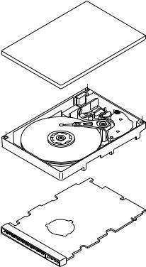
Refer to Figure 2 for an exploded view of the drive. This exploded view is for information only—never disassemble the HDA and do not attempt to service items in the sealed enclosure (heads, media, actuator, etc.) as this requires special facilities. The drive contains no replaceable parts. Opening the HDA voids your warranty.
Barracuda 4LP drives use a dedicated landing zone at the innermost radius of the media to eliminate the possibility of destroying or degrading data by landing in the data zone. The drive automatically goes to the landing zone when power is removed.
An automatic shipping lock prevents potential damage to the heads and discs that results from movement during shipping and handling. The shipping lock automatically disengages when power is applied to the drive and the head load process begins.
Barracuda 4LP drives decode track 0 location data from the servo data embedded on each surface to eliminate mechanical transducer adjustments and related reliability concerns.
A high-performance actuator assembly with a low-inertia, balanced, patented, straight-arm design provides excellent performance with minimal power dissipation.
Figure 2. Barracuda 4LP family drive
Barracuda 4LP Product Manual, Rev. D |
7 |
3.1Standard features
The Barracuda 4LP Family has the following standard features:
•Integrated SCSI controller
•Single-ended or differential SCSI drivers and receivers
•8 bit and 16 bit I/O data bus models available
•Asynchronous and synchronous data transfer protocol
•Firmware downloadable via SCSI interface
•Selectable even byte sector sizes from 180 to 4,096 bytes/sector
•Programmable drive capacity
•Programmable sector reallocation scheme
•Flawed sector reallocation at format time
•Programmable auto write and read reallocation
•Reallocation of defects on command (Post format)
•128 bit Reed-Solomon error correcting code
•Sealed head and disc assembly
•No preventative maintenance or adjustment required
•Dedicated laser textured head landing zone
•Embedded servo data rather than a separate servo data surface
•Self diagnostics performed when power is applied to the drive
•1:1 Interleave
•Zoned bit recording (ZBR)
•Vertical, horizontal, or top down mounting
•Dynamic spindle brake
•Active IC terminators enabled by jumpers (“N” and “W” models only)
•512 K byte data buffer
•Hot plug compatibility (section 9.6.4.3 lists proper host connector needed) for “WC” and “DC” model drives
•SCAM (SCSI Configured AutoMagically) plug-n-play level 1 compliant as shipped. Level 2 is a factory installed option.
•Low audible noise for office environment
•Low power consumption
3.2Media characteristics
The media used on the drive has a diameter of approximately 3.5 inches (86 mm). The aluminum substrate is coated with a thin film magnetic material, overcoated with a proprietary protective layer for improved durability and environmental protection.
3.3Performance
•Supports industry standard Ultra SCSI interface (also called “Fast-20 SCSI”) [1]
•Programmable multi-segmentable cache buffer
•7200 RPM spindle. Average latency = 4.17 ms
•Command queuing of up to 64 commands
•Background processing of queue
•Supports start and stop commands (spindle stops spinning)
3.4Reliability
•1,000,000 hour MTBF
•LSI circuitry
•Balanced low mass rotary voice coil actuator
•Incorporates industry-standard Self-Monitoring, Analysis and Reporting Technology (S.M.A.R.T.)
•Incorporates Seek To Improve Reliability algorithm (STIR)
•5-year warranty
[1]Note: Some host adapter companies support the term “Fast-20 SCSI.”
8 |
Barracuda 4LP Product Manual, Rev. D |
3.5Unformatted and formatted capacities
Formatted capacity depends on the number of spare reallocation sectors reserved and the number of bytes per sector. The following table shows the standard OEM model capacities:
|
Formatted [1] |
|
|
Data Block Size |
|
|
512 Byte/Sector |
Unformatted |
ST34371 |
4.35 GB [2] |
5.31 GB |
ST32171 |
2.16 GB [2] |
2.65 GB |
ST34571 |
4.55 GB [2] |
5.54 GB |
ST32271 |
2.26 GB [2] |
2.77 GB |
Notes.
[1]Sector size selectable at format time. Users having the necessary equipment may modify the data block size before issuing a format command and obtain different formatted capacities than those listed. User available capacity depends on spare reallocation scheme selected. See Mode Select Command and Format Command in the SCSI Interface Product Manual P/N 77738479.
[2]Sparing equivalent to eighty spare sectors per eight cylinder region. Spares are located at the end of each sparing region.
3.6Programmable drive capacity
Using the Mode Select command, the drive can change its capacity to something less than maximum. See Table 5.2.1-13 in the SCSI I/O Product Manual, P/N 77738479, Rev. G. Refer to the Parameter list block descriptor, bytes 1, 2 and 3. A value of zero in bytes 1, 2 and 3 indicates that the drive shall not change the capacity it is currently formatted to have. A number in bytes 1, 2 and 3 that is less than the maximum number of LBAs changes the total drive capacity to the value in the block descriptor bytes 1, 2 and 3. A value greater than the maximum number of LBAs is rounded down to the maximum capacity.
3.7Factory installed accessories
OEM Standard drives are shipped with Installation Guide P/N 77767492 (unless otherwise specified). The factory also ships with the drive a small bag of the two jumper plug types used for the J6, J2 and J1-Aux option select jumper headers.
3.8Options (factory installed)
All customer requested options are incorporated during production or packaged at the manufacturing facility before shipping. Some of the options available are (not an exhaustive list of possible options):
•Other capacities can be ordered depending on sparing scheme and sector size requested.
•Single unit shipping pack. The drive is normally shipped in bulk packaging to provide maximum protection against transit damage. Units shipped individually require additional protection as provided by the single unit shipping pack. Users planning single unit distribution should specify this option.
•The Installation Guide (P/N 77767492) is usually included with each standard OEM drive shipped, but extra copies may be ordered.
•Level 2 SCAM compliance.
3.9Accessories (user installed)
The following accessories are available. All accessories may be installed in the field.
• Single unit shipping pack.
Barracuda 4LP Product Manual, Rev. D |
9 |
4.0Performance characteristics
4.1Internal drive characteristics (transparent to user)
|
ST34371 |
ST32171 |
ST34571 |
ST32271 |
|
Drive Capacity |
5.31 |
2.65 |
5.54 |
2.77 |
GByte (UNF, rounded off values) |
Read/Write Heads |
10 |
5 |
10 |
5 |
|
Bytes/Track |
102,500 |
102,500 |
106,980 |
106,980 Bytes (Avg, rounded off values) |
|
Bytes/Surface |
531 |
531 |
554 |
554 |
Mbytes (UNF, rounded off values) |
Tracks/Surface, Total |
5,178 |
5,178 |
5,178 |
5,178 |
Tracks (user accessible) |
Tracks/Inch |
5,555 |
5,555 |
5,555 |
5,555 |
TPI |
Peak Bits/Inch |
123,000 |
123,000 |
128,000 |
128,000 |
BPI |
Internal Data Rate |
80-122 |
80-122 |
83-126 |
83-126 Mbits/sec (variable with zone) |
|
Disc Rotational Speed |
7,200 |
7,200 |
7,200 |
7,200 |
r/min |
Average Rotational Latency |
4.17 |
4.17 |
4.17 |
4.17 |
ms |
4.2SCSI Seek performance characteristics (visible to user) [6]*
The values given in Section 4.2.1 apply to all models of the Barracuda 4LP family unless otherwise specified. Refer to Section 9.10 and to the SCSI-2 Interface Product Manual 77738479 for additional timing details.
4.2.1Access time [8]
Including Controller Overhead (without disconnect) [1] [4]
|
|
|
|
Drive Level |
|
|
|
|
|
Read |
Write |
|
|
|
|
ms |
|
Average |
– |
Typical |
[3] |
9.4 |
10.4 |
|
|
Max. |
[2] |
10.8 |
11.3 |
Single Track |
– |
Typical |
[3] |
2.0 |
2.1 |
|
|
Max. |
[2] |
2.2 |
2.3 |
Full Stroke |
– |
Typical |
[3] |
17.5 |
18.5 |
|
|
Max. |
[2] |
20.0 |
20.5 |
*[ ] All notes for Section 4.2 are listed at end of Section 4.2.3.
10 |
Barracuda 4LP Product Manual, Rev. D |
4.2.2Format command execution time (minutes) [1]*
|
ST34371/ST34571 |
ST32171/ST32271 |
Maximum (with verify) |
95 |
50 |
Maximum (no verify) |
65 |
35 |
4.2.3Generalized performance characteristics
Minimum sector interleave |
1 to 1 |
Data buffer transfer rate to/from disc media (one 512-byte sector):
Min. |
[4]* |
9.5 |
MByte/sec |
|
Avg. |
[4] |
13.2 |
MByte/sec |
|
Max. |
[4] |
15.0 |
MByte/sec |
|
Data buffer transfer rate to/from disc media: (< 1 track): |
||||
Min. |
[4] |
7.1 |
MByte/sec |
divided by (interleave factor) |
Avg. |
[4] |
10.2 |
MByte/sec |
divided by (interleave factor) |
Max. |
[4] |
11.7 |
MByte/sec |
divided by (interleave factor) |
SCSI interface data transfer rate (asynchronous) [5]:
Maximum instantaneous
Maximum average
Synchronous transfer rate for SCSI Fast-20 (Ultra SCSI): (8 bit data bus models)
Synchronous transfer rate for SCSI Fast-20 (Ultra SCSI): (16 bit data bus models)
Synchronous transfer rate for fast SCSI-2: (8 bit data bus models)
Synchronous transfer rate for fast SCSI-2: (16 bit data bus models).
Sector Sizes:
Default
Variable
Read/write consecutive sectors on a track |
Yes |
Flaw reallocation performance impact (for flaws reallocated at format time using |
Negligible |
the spare sectors per sparing region reallocation scheme.) |
|
Overhead time for head switch (512 byte sectors) in sequential mode |
1 msec |
Overhead time for one track cylinder switch in sequential mode |
<2.4 msec (typical) |
Average rotational latency |
4.17 msec |
*[ ] Notes listed after Section 4.2.3. |
|
Barracuda 4LP Product Manual, Rev. D |
11 |
Notes for Section 4.2.
[1]Execution time measured from receipt of the last Byte of the Command Descriptor Block (CDB) to the request for a Status Byte Transfer to the Initiator (excluding connect/disconnect).
[2]Maximum times are specified over the worst case conditions of temperature, voltage margins and drive orientation. When comparing specified access times, care should be taken to distinguish between typical access times and maximum access times. The best comparison is obtained by system benchmark tests conducted under identical conditions. Maximum times do not include error recovery.
[3]Typical Access times are measured under nominal conditions of temperature, voltage, and horizontal orientation as measured on a representative sample of drives.
[4]Assumes no errors and no sector has been relocated.
[5]Rate measured from the start of the first sector transfer to or from the Host.
[6]Assumes system ability to support the rates listed and no cable loss.
[7]Simulated.
[8]Access time = controller overhead + average seek time
Access to data = controller overhead + average seek time + latency time
4.3Start/stop time
After DC power at nominal voltage has been applied, the drive becomes ready within 20 seconds if the Motor Start Option is disabled (i.e. the motor starts as soon as the power has been applied). If a recoverable error condition is detected during the start sequence, the drive executes a recovery procedure which may cause the time to become ready to exceed 20 seconds. During spin up to ready time the drive responds to some commands over the SCSI interface in less than 3 seconds after application of power. Stop time is less than 20 seconds from removal of DC power.
If the Motor Start Option is enabled, the internal controller accepts the commands listed in the SCSI Interface Product Manual less than 3 seconds after DC power has been applied. After the Motor Start Command has been received the drive becomes ready for normal operations within 13 seconds typically (excluding an error recovery procedure). The Motor Start Command can also be used to command the drive to stop the spindle (see SCSI Interface Product Manual, 77738479).
There is no power control switch on the drive.
4.4Prefetch/multi-segmented cache control
The drive provides prefetch (read look-ahead) and multi-segmented cache control algorithms that in many cases can enhance system performance. “Cache” as used herein refers to the drive buffer storage space when it is used in “cache” operations. To select prefetch and cache features the host sends the Mode Select command with the proper values in the applicable bytes in Mode Page 08h (see SCSI Interface Product Manual, 77738479). Prefetch and cache operation are independent features from the standpoint that each is enabled and disabled independently via the Mode Select command. However, in actual operation the prefetch feature overlaps cache operation somewhat as is noted in Section 4.5.1 and 4.5.2.
All default cache and prefetch Mode parameter values (Mode Page 08h) for standard OEM versions of this drive family are given in Tables 8a and 8b.
4.5Cache operation
In general, 480 Kbytes of the 512 Kbytes of physical buffer space in the drive can be used as storage space for cache operations. The buffer can be divided into logical segments (Mode Select Page 08h, byte 13) from which data is read and to which data is written. The drive maintains a table of logical block disk medium addresses of the data stored in each segment of the buffer. If cache operation is enabled (RCD bit = 0 in Mode Page 08h, byte 2, bit 0. See SCSI Interface Product Manual P/N 77738479), data requested by the host with a Read command is retrieved from the buffer (if it is there), before any disc access is initiated. If cache operation is not enabled, the buffer (still segmented with required number of segments) is still used, but only as circular buffer segments during disc medium read operations (disregarding Prefetch operation for the moment). That is, the drive does not check in the buffer segments for the requested read data, but goes directly to the medium to retrieve it. The retrieved data merely passes through some buffer segment on the way to the host. On a cache “miss”, all data transfers to the host are in accordance with “buffer-full” ratio rules. On a cache “hit” the drive ignores the “buffer-full” ratio rules. See explanations associated with Mode page 02h (disconnect/reconnect control) in the SCSI Interface Product Manual, 77738479.
12 |
Barracuda 4LP Product Manual, Rev. D |
The following is a simplified description of a read operation with cache operation enabled:
Case A - A Read command is received and the first logical block (LB) is already in cache:
1.Drive transfers to the initiator the first LB requested plus all subsequent contiguous LB’s that are already in the cache. This data may be in multiple segments.
2.When the requested LB is reached that is not in any cache segment, the drive fetches it and any remaining requested LBs from the disc and puts them in a segment of the cache. The drive transfers the remaining requested LBs from the cache to the host in accordance with the disconnect/reconnect specification mentioned above.
3.If the prefetch feature is enabled, refer to Section 4.5.2 for operation from this point.
Case B - A Read command requests data, the first LB of which is not in any segment of the cache:
1.The drive fetches the requested LB’s from the disc and transfers them into a segment, and from there to the host in accordance with the disconnect/reconnect specification referred to in case A.
2.If the prefetch feature is enabled, refer to Section 4.5.2 for operation from this point.
Each buffer segment is actually a self-contained circular storage (wrap-around occurs), the length of which is an integer number of disc medium sectors. The wrap-around capability of the individual segments greatly enhances the buffer’s overall performance as a cache storage, allowing a wide range of user selectable configurations, which includes their use in the prefetch operation (if enabled), even when cache operation is disabled (see Section 4.5.2). The number of segments may be selected using the Mode Select command, but the size can not be directly selected. Size is selected only as a by-product of selecting the segment number specification. The size in Kbytes of each segment is not reported by the Mode Sense command page 08h, bytes 14 and 15. The value 0XFFFF is always reported. If a size specification is sent by the host in a Mode Select command (bytes 14 and 15) no new segment size is set up by the drive, and if the “STRICT” bit in Mode page 00h (byte 2, bit 1) is set to one, the drive responds as it does for any attempt to change unchangeable parameters (see SCSI I/O Product Manual 77738479). The drive supports operation of any integer number of segments from 1 to 16.
4.5.1Caching write data
Write caching is a write operation by the drive that makes use of a drive buffer storage area where the data to be written to the medium is stored in one or more segments while the drive performs the write command.
Write caching is enabled along with read caching. For write caching, the same buffer space and segmentation is used as set up for read functions. The buffer segmentation scheme is set up or changed independently, having nothing to do with whether or not read and write caching is enabled or disabled. When a write command is issued, the cache is first checked to see if any logical blocks that are to be written are already stored in the cache from a previous read or write command. If there are, the respective cache segments are cleared. The new data is cached for subsequent Read commands.
If the number of write data logical blocks exceeds the size of the segment being written into when the end of the segment is reached, the data is written into the beginning of the same cache segment, overwriting the data that was written there at the beginning of the operation. However, the drive does not overwrite data that has not yet been written to the medium.
Tables 8a, 8b and 9a, 9b show Mode default settings for the drives.
4.5.2Prefetch operation
If the Prefetch feature is enabled, data in contiguous logical blocks on the disc immediately beyond that which was requested by a Read command can be retrieved and stored in the buffer for immediate transfer from the buffer to the host on subsequent Read commands that request those logical blocks (this is true even if “cache” operation is disabled). Though the prefetch operation uses the buffer as a “cache”, finding the requested data in the buffer is a prefetch “hit”, not a “cache” operation “hit”. Prefetch is enabled using Mode Select page 08h, byte 12, bit 5 (Disable Read Ahead - DRA bit). DRA bit = 0 enables prefetch. Since data that is prefetched replaces data already in some buffer segment(s), the host can limit the amount of prefetch data to optimize system performance. The max prefetch field (bytes 8 and 9) limits the amount of prefetch. The drive does not use the prefetch “ceiling” field (bytes 10 and 11).
Barracuda 4LP Product Manual, Rev. D |
13 |
During a prefetch operation, the drive crosses a cylinder boundary to fetch more data only if the Discontinuity (DISC) bit is set to one in bit 4 of byte 2 of Mode parameters page 08h.
Whenever prefetch (read look-ahead) is enabled (enabled by DRA = 0), it operates under the control of ARLA (Adaptive Read Look-Ahead). If the host uses software interleave, ARLA enables prefetch of contiguous blocks from the disc when it senses that a prefetch “hit” will likely occur, even if two consecutive read operations were not for physically contiguous blocks of data (e.g. “software interleave”). ARLA disables prefetch when it decides that a prefetch “hit” will not likely occur. If the host is not using software interleave, and if two sequential read operations are not for contiguous blocks of data, ARLA disables prefetch, but as long as sequential read operations request contiguous blocks of data, ARLA keeps prefetch enabled.
Barracuda 4LP Product Manual, Rev. D |
15 |
5.0Reliability specifications
The following reliability specifications assume correct host/drive operational interface, including all interface timings, power supply voltages, environmental requirements and drive mounting constraints (see Section 8.4).
Seek Errors |
Less than 10 in 108 seeks |
Read Error Rates [1] |
|
Recovered Data |
Less than 10 errors in 1011 bits transferred (OEM default settings) |
Unrecovered Data |
Less than 1 sector in 1014 bits transferred (OEM default settings) |
Miscorrected Data |
Less than 1 sector in 1021 bits transferred |
MTBF |
1,000,000 hours |
Service Life |
5 years |
Preventive Maintenance |
None required |
Note.
[1]Error rate specified with automatic retries and data correction with ECC enabled and all flaws reallocated.
5.1Error rates
The error rates stated in this specification assume the following:
•The drive is operated per this specification using DC power as defined in this manual (see Section 6.2).
•The drive has been formatted with the SCSI FORMAT commands.
•Errors caused by media defects or host system failures are excluded from error rate computations. Refer to Section 3.2, “Media Characteristics.”
5.1.1Environmental interference
When evaluating systems operation under conditions of Electromagnetic Interference (EMI), the performance of the drive within the system shall be considered acceptable if the drive does not generate an unrecoverable condition.
An unrecoverable error, or unrecoverable condition, is defined as one that:
•Is not detected and corrected by the drive itself;
•Is not capable of being detected from the error or fault status provided through the drive or SCSI interface; or
•Is not capable of being recovered by normal drive or system recovery procedures without operator intervention.
5.1.2Read errors
Before determination or measurement of read error rates:
•The data that is to be used for measurement of read error rates must be verified as being written correctly on the media.
•All media defect induced errors must be excluded from error rate calculations.
5.1.3Write errors
Write errors can occur as a result of media defects, environmental interference, or equipment malfunction. Therefore, write errors are not predictable as a function of the number of bits passed.
If a write error unrecoverable occurs because of an equipment malfunction in the drive, the error is classified as a failure affecting MTBF. Unrecoverable write errors are those which cannot be corrected within two attempts at writing the record with a read verify after each attempt (excluding media defects).

16 |
Barracuda 4LP Product Manual, Rev. D |
5.1.4Seek errors
A seek error is defined as a failure of the drive to position the heads to the addressed track. There shall be no more than one recoverable seek errors in 107 physical seek operations. After detecting an initial seek error, the drive automatically performs an error recovery process. If the error recovery process fails, a seek positioning error (15h) is reported with a Medium error (3h) or Hardware error (4h) reported in the Sense Key. This is an unrecoverable seek error. Unrecoverable seek errors are classified as failures for MTBF calculations. Refer to Section 5.1.1.4 of SCSI-2 Interface Product Manual P/N 77738479 for Request Sense information.
5.2Reliability and service
You can enhance the reliability of Barracuda 4LP disc drives by ensuring that the drive receives adequate cooling. Section 6.4.1 provides temperature measurements and other information that may be used to enhance the service life of the drive. Section 8.3.1 provides recommended air-flow information.
5.2.1Mean time between failure
The production disc drive shall achieve an MTBF of 1,000,000 hours when operated in an environment that ensures the case temperatures specified in Section 6.4.1, Table 3, Column 2 are not exceeded. Short-term excursions up to the specification limits of the operating environment will not affect MTBF performance.
The following expression defines MTBF
Estimated power-on operating hours in the period
MTBF per measurement period |
= |
Number of drive failures in the period
Estimated power-on operation hours means power-up hours per disc drive times the total number of disc drives in service. Each disc drive shall have accumulated at least nine months of operation. Data shall be calculated on a rolling average base for a minimum period of six months.
Drive failure means any stoppage or substandard performance caused by drive malfunction.
5.2.2Preventive maintenance
No routine scheduled preventive maintenance shall be required.
5.2.3Service life
The drive shall have a useful service life of five years. Depot repair or replacement of major parts is permitted during the lifetime (see Section 5.2.4).
5.2.4Service philosophy
Special equipment is required to repair the drive HDA. In order to achieve the above service life, repairs must be performed only at a properly equipped and staffed service and repair facility. Troubleshooting and repair of PCBs in the field is not recommended, because of the extensive diagnostic equipment required for effective servicing. Also, there are no spare parts available for this drive. Drive warranty is voided if the HDA is opened.
5.2.5Service tools
No special tools are required for site installation or recommended for site maintenance. Refer to Section 5.2.4. The depot repair philosophy of the drive precludes the necessity for special tools. Field repair of the drive is not practical since there are no user purchasable parts in the drive.
Barracuda 4LP Product Manual, Rev. D |
17 |
5.2.6Hot plugging Barracuda 4LP disc drives
Caution: Hot-plug drives are not designed for simultaneous power disconnection and physical removal.
During power-up and power-down periods, the hot SCSI connect/disconnect capability does not produce glitches or any corruptions on an active SCSI bus. Barracuda 4LP drives conform to the SCSI-3 standard requirements for glitch-free power-on and power-off. The drive maintains the high-impedance state of the device connector contacts during a power cycle until the transceiver is enabled.
Note. The systems integrator must ensure that no temperature, energy, voltage hazard, or ESD potential is presented during the hot connect/disconnect operation.
Procedure:
1.Configure the drive with no connection between the drive and the TRMPWR signal on the SCSI bus. To accomplish this, remove all jumpers from connector J2 pins 1, 2, 3, and 4.
2.Ensure that all SCSI devices on the bus have receivers that conform to the SCSI-3 standard.
3.Eliminate all I/O processes for the drive.
4.Wait until the drive motor and discs have come to a complete stop prior to changing the plane of operation, ensuring data integrity.
5.Insert or remove the drive after meeting the following conditions:
Caution: Do not hot-plug the first or last device on the SCSI bus (the SCSI bus termination must be external to the drive you are inserting or removing).
a.If you are inserting the drive, connect its power ground and logic ground at least 1 millisecond before coming into contact with the bus connector. Maintain these ground connections during and after connecting the device to the bus.
b.If you are removing the device, maintain its power ground and logic ground connection for at least 1 millisecond after disconnecting the device from the bus.
c.You may simultaneously switch the power to the electronics and mechanics of the drive with the bus contacts, if the power distribution system is able to maintain adequate power stability to other devices during the transition and if you have met the grounding requirements given in steps 5a and 5b.
d.Ensure that the drive carrier discharges all static electricity prior to inserting the drive into the system.
Note. Do not remove or add terminator power or resistance to the SCSI bus while hot plugging a disc drive.
5.2.7S.M.A.R.T.
This feature not implemented by this drive family.
5.2.8Product warranty
Beginning on the date of shipment to customer and continuing for a period of five years, Seagate warrants that each product (including components and subassemblies) or spare part that fails to function properly under normal use due to defect in materials on workmanship or due to nonconformance to the applicable specifications will be repaired or replaced, at Seagate’s option and at no charge to customer, if returned by customer at customer’s expense to Seagate’s designated facility in accordance with Seagate’s Warranty Procedure. Seagate will pay for transporting the repair or replacement item to customer. For more detailed warranty information refer to the Standard terms and conditions of Purchase for Seagate products.
Shipping
When transporting or shipping a drive, a Seagate approved container must be used. Keep your original box. They are easily identified by the Seagate Approved Package label. Shipping a drive in a non-approved container voids the drive warranty.
Seagate repair centers may refuse receipt of components improperly packaged or obviously damaged in transit. Contact your Authorized Seagate Distributor to purchase additional boxes. Seagate recommends shipping by an air-ride carrier experienced in handling computer equipment.
18 |
Barracuda 4LP Product Manual, Rev. D |
Product repair and return information
Seagate customer service centers are the only facilities authorized to service Seagate drives. Seagate does not sanction any third-party repair facilities. Any unauthorized repair or tampering with the factory-seal voids the warranty.
Barracuda 4LP Product Manual, Rev. D |
19 |
6.0Physical/electrical specifications
This section provides information relating to the physical and electrical characteristics of the Barracuda 4LP drive.
6.1AC power requirements
None
6.2DC power requirements
The voltage and current requirements for a single drive are shown in the following table. Values indicated apply at the drive power connector. The single ended power requirements includes the internal disc drive SCSI I/O termination. The table shows current values in Amperes.
Table 2: |
DC power requirements |
|
|
|
|
|
|
|
|
|
|
|
||||
|
|
|
|
|
|
|
|
|
|
|
|
|
|
|
|
|
|
|
|
|
|
|
|
ST34371/ST34571 |
|
|
ST32171/ST32271 |
|
|
||||
|
|
|
|
|
|
|
|
|
|
|
|
|
|
|
|
|
|
|
|
|
|
|
|
N/W/WC |
|
|
WD/DC |
|
N/W/WC |
|
|
WD/DC |
|
|
|
|
|
|
|
Notes |
Single-ended |
|
Differential |
Single-ended |
|
Differential |
||||
|
|
|
|
|
|
|
|
|
|
|
|
|
|
|
|
|
|
|
|
|
|
|
|
|
|
|
|
|
|
|
|
|
|
Voltage |
|
|
|
|
|
|
+5 V |
+12 V |
|
+5 V |
+12 V |
+5 V |
+12 V |
|
+5 V |
+12 V |
|
|
|
|
|
|
|
|
|
|
|
|
|
|
|
|
|
Regulation |
|
|
|
|
|
[5] |
±5% |
±5%[2] |
|
±5% |
±5%[2] |
±5% |
±5%[2] |
±5% |
±5%[2] |
|
|
|
|
|
|
|
|
|
|
|
|
|
|||||
Maximum operating current DC3σ |
[1] |
0.81 |
0.95 |
|
1.21 |
0.95 |
0.81 |
0.85 |
|
1.21 |
0.85 |
|||||
|
|
|
|
|
|
|
|
|
|
|
|
|
|
|
||
|
|
|
|
|
|
[1] |
0.46 |
0.54 |
|
0.70 |
0.54 |
0.46 |
0.52 |
|
0.70 |
0.52 |
Average idle current DCX |
|
|
|
|||||||||||||
|
|
|
|
|
|
|
|
|
|
|
|
|||||
Maximum starting current |
|
|
|
|
|
|
|
|
|
|
|
|||||
(peak DC) DC3σ |
[3] |
0.78 |
2.44 |
|
1.1 |
2.44 |
0.78 |
2.00 |
|
1.1 |
2.00 |
|||||
(peak AC) AC3σ |
[3] |
|
3.1 |
|
|
3.1 |
|
3.1 |
|
|
3.1 |
|||||
|
|
|
|
|
|
|
|
|
|
|
|
|||||
Delayed motor start (max) DC3σ |
[1][4] |
0.48 |
0.20 |
|
0.90 |
0.20 |
0.50 |
0.20 |
|
0.90 |
0.20 |
|||||
|
|
|
|
|
|
|
|
|
|
|
|
|||||
Peak operating current |
|
|
|
|
|
|
|
|
|
|
|
|||||
|
|
|
[1][6] |
0.75 |
0.76 |
|
1.05 |
0.76 |
0.72 |
0.73 |
|
0.91 |
0.73 |
|||
Typical DCX |
|
|
|
|||||||||||||
Maximum DC3σ |
[1][6] |
0.81 |
0.95 |
|
1.21 |
0.95 |
0.81 |
0.85 |
|
1.21 |
0.85 |
|||||
Maximum (Peak) 3σ |
|
1.5 |
2.5 |
|
2.0 |
2.5 |
1.5 |
2.3 |
|
2.0 |
2.3 |
|||||
|
|
|
|
|
|
|
|
|
|
|
|
|
|
|
|
|
Notes.
[1]Measured with average reading DC ammeter. Instantaneous +12 V current peaks will exceed these values.
[2]A –10% droop is permissible during initial start of spindle, and must return to ±5% before 7,200 rpm is reached. The ±5% must be maintained after the drive signifies that its power-up sequence has been completed and that the drive is able to accept selection by the host initiator.
[3]See +12 V current profile in Figure 3.
[4]This condition occurs when the Motor Start Option is enabled and the drive has not yet received a Start Motor command.
[5]See Section 6.2.1 “Conducted Noise Immunity.” Specified voltage tolerance is inclusive of ripple, noise, and transient response.
[6]Operating condition is defined as random seek read operations with a block count of 64 and SCSI discon-
nect enabled.
[7]
General Notes from Table 2:
1.Minimum current loading for each supply voltage is not less than 4% of the maximum operating current shown.
2.The +5 and +12 volt supplies shall employ separate ground returns.
3.Where power is provided to multiple drives from a common supply, careful consideration for individual drive power requirements should be noted. Where multiple units are powered on simultaneously, the peak starting current must be available to each device.
Loading...