


Seagate ST31250N, ST31250ND, ST31250W, ST31250WD, ST31250WC Product Manual
...Barracuda 2LP Disc Drive
ST31250N/ND, ST31250W/WD,
ST31250WC/DC, ST32550N/ND,
ST32550W/WD, ST32550WC/DC
Product Manual, Volume 1

Barracuda 2LP Disc Drive
ST31250N/ND, ST31250W/WD,
ST31250WC/DC, ST32550N/ND,
ST32550W/WD, ST32550WC/DC
Product Manual, Volume 1
© 1996 Seagate Technology, Inc. All rights reserved Publication number: 83328930, Rev. D
January 1996
Seagate®, Seagate Technology®, and the Seagate logo are registered trademarks of Seagate Technology, Inc. Barracuda™ is a trademark of Seagate Technology, Inc. Other product names are registered trademarks or trademarks of their owners.
Seagate reserves the right to change, without notice, product offerings or specifications. No part of this publication may be reproduced in any form without written permission from Seagate Technology, Inc.
Revision status summary sheet
|
|
|
Sheets |
Revision |
Date |
Writer/Engineer |
Affected |
A |
7/14/94 |
L. Newman/J. Olson |
All |
B |
9/21/94 |
L. Newman/J. Olson |
36, 37, 43, 51, 57, 61, |
|
|
|
64, 66 |
C |
3/20/95 |
L. Newman/J. Olson |
1, 9, 12, 14, 24, 25, 26, 27, |
|
|
|
28, 29, 33, 34, 35, 36, 39, |
|
|
|
41, 42, 47, 48, 50, 52, 55, |
|
|
|
57, 58, 59, 60, 61, 62, 63, |
|
|
|
64, 66, 68, 69, 70, 71, 73, |
|
|
|
80, 82 |
D |
1/9/96 |
L. Newman/J. Olson |
3, 18, 36, 39, 40, 41, 48, 50, |
|
|
|
51, 53, 54, 57, 65, 72 |
Note. Product Manual 83328930 is Volume 1 of a two-volume document with the SCSI interface information in the Volume 2 SCSI-2 Interface Product Manual, Part Number 77738479.
Contents
1.0 |
Scope .............................................................................................................................. |
|
1 |
|
2.0 Applicable standard and reference documentation ...................................................... |
3 |
|||
|
2.1 |
Standards ................................................................................................................. |
3 |
|
|
2.2 |
Applicable reference documents ............................................................................... |
3 |
|
3.0 |
General description .......................................................................................................... |
5 |
||
4.0 |
Standard features ............................................................................................................. |
7 |
||
|
4.1 |
Performance ............................................................................................................. |
7 |
|
|
|
4.1.1 |
Reliability ...................................................................................................... |
7 |
|
4.2 |
Unformatted and formatted capacities ...................................................................... |
8 |
|
|
4.3 |
Options ..................................................................................................................... |
8 |
|
|
4.4 |
Installation ................................................................................................................. |
9 |
|
5.0 |
Performance characteristics ........................................................................................... |
11 |
||
|
5.1 |
Internal drive characteristics ..................................................................................... |
11 |
|
|
5.2 |
SCSI seek performance characteristics .................................................................... |
11 |
|
|
|
5.2.1 |
Seek time ...................................................................................................... |
13 |
|
|
5.2.2 Format drive command execution time ......................................................... |
13 |
|
|
5.3 |
General performance characteristics ........................................................................ |
14 |
|
|
5.4 |
Start/stop time ........................................................................................................... |
15 |
|
|
5.5 |
Prefetch/multi-segmented cache control ................................................................... |
15 |
|
|
5.6 |
Caching write data .................................................................................................... |
16 |
|
|
5.7 |
Synchronized spindle operation ................................................................................ |
17 |
|
6.0 |
Reliability specifications .................................................................................................. |
21 |
||
|
6.1 |
Error rates ................................................................................................................. |
21 |
|
|
|
6.1.1 |
Environmental interference ........................................................................... |
21 |
|
|
6.1.2 |
Write errors ................................................................................................... |
21 |
|
|
6.1.3 |
Seek errors ................................................................................................... |
22 |
|
6.2 |
Reliability and service ............................................................................................... |
22 |
|
|
|
6.2.1 Mean time between failures (MTBF) ............................................................. |
22 |
|
|
|
6.2.2 |
Air flow .......................................................................................................... |
22 |
|
|
6.2.3 |
Preventive maintenance ............................................................................... |
30 |
|
|
6.2.4 |
Service life .................................................................................................... |
30 |
|
|
6.2.5 |
Service philosophy ........................................................................................ |
30 |
|
|
6.2.6 |
Installation..................................................................................................... |
30 |
|
|
6.2.7 |
Service tools ................................................................................................. |
30 |
|
|
6.2.8 Hot plugging Barracuda 2LP disc drives ....................................................... |
30 |
|
vi |
|
|
Barracuda 2LP Product Manual, Rev. D |
|
7.0 |
Physical/electrical specifications .................................................................................... |
33 |
||
|
7.1 |
AC power requirements ............................................................................................ |
33 |
|
|
7.2 |
DC power requirements ............................................................................................ |
33 |
|
|
|
7.2.1 |
Conducted noise immunity ............................................................................ |
34 |
|
|
7.2.2 |
Power sequencing ........................................................................................ |
34 |
|
|
7.2.3 |
12V current profile ........................................................................................ |
35 |
|
7.3 |
Heat/power dissipation .............................................................................................. |
36 |
|
|
7.4 |
Environmental limits .................................................................................................. |
36 |
|
|
|
7.4.1 |
Temperature ................................................................................................. |
36 |
|
|
7.4.2 |
Relative humidity .......................................................................................... |
36 |
|
|
7.4.3 |
Effective altitude (sea level) .......................................................................... |
37 |
|
|
7.4.4 |
Shock and vibration ...................................................................................... |
37 |
|
|
7.4.5 |
Air cleanliness ............................................................................................... |
38 |
|
|
7.4.6 |
Acoustics ...................................................................................................... |
38 |
|
7.5 |
Electromagnetic compatibility .................................................................................... |
38 |
|
|
7.6 |
Mechanical specifications ......................................................................................... |
39 |
|
|
|
7.6.1 |
Drive orientation ............................................................................................ |
42 |
|
|
7.6.2 |
Cooling ......................................................................................................... |
42 |
|
|
7.6.3 |
Drive mounting .............................................................................................. |
42 |
8.0 |
Media characteristics ....................................................................................................... |
43 |
||
|
8.1 |
Media description ...................................................................................................... |
43 |
|
9.0 Defect and error management ......................................................................................... |
45 |
|||
|
9.1 |
Defects and errors .................................................................................................... |
45 |
|
10.0 Option/configuration headers ......................................................................................... |
47 |
|||
|
10.1 Drive ID/option select headers .................................................................................. |
47 |
||
|
|
10.1.1 |
ST31250N/ND and ST32550N/ND configuration .......................................... |
47 |
|
|
10.1.2 |
ST31250W/WD and ST32550W/WD configuration ....................................... |
50 |
|
|
10.1.3 |
ST31250WC/DC and ST32550WC/DC configuration .................................... |
53 |
|
10.2 |
Synchronized spindles interface ............................................................................... |
55 |
|
|
|
10.2.1 |
Electrical description ..................................................................................... |
55 |
|
10.3 |
Grounding ................................................................................................................. |
57 |
|
11.0 Interface requirements ..................................................................................................... |
59 |
|||
|
11.1 |
General description ................................................................................................... |
59 |
|
|
11.2 SCSI interface messages supported ......................................................................... |
59 |
||
|
11.3 SCSI interface commands supported ........................................................................ |
60 |
||
|
|
11.3.1 |
Inquiry data ................................................................................................... |
62 |
|
|
11.3.2 |
Mode sense data .......................................................................................... |
63 |
|
11.4 SCSI bus conditions and miscellaneous features supported ..................................... |
66 |
||
Barracuda 2LP Product Manual, Rev. D |
vii |
||
11.5 |
Synchronous data transfer ........................................................................................ |
67 |
|
|
11.5.1 Synchronous data transfer periods supported .............................................. |
67 |
|
|
11.5.2 |
REQ/ACK offset ............................................................................................ |
67 |
11.6 |
DC cable and connector ........................................................................................... |
68 |
|
11.7 |
SCSI physical interface ............................................................................................. |
68 |
|
|
11.7.1 |
Physical characteristics ................................................................................ |
70 |
|
11.7.2 |
Connector requirements ............................................................................... |
71 |
|
11.7.3 |
Electrical description ..................................................................................... |
72 |
11.8 |
SCSI non-wide physical interface ............................................................................. |
76 |
|
11.9 |
SCSI wide physical interface ..................................................................................... |
79 |
|
11.10 SCSI single-connector attachment (SCA) physical interface ..................................... |
82 |
||
Index .......................................................................................................................................... |
|
|
87 |
Figures
Figure 1. |
Barracuda 2LP disc drive (ST32550N drive shown) .................................................. |
1 |
Figure 2. |
Barracuda 2LP disc drive (exploded view) ................................................................. |
5 |
Figure 3. |
ASA I OEM thermal calibration ................................................................................. |
13 |
Figure 4. |
Synchronized drive interconnect diagram .................................................................. |
17 |
Figure 5. |
Synchronized reference signal characteristics ........................................................... |
18 |
Figure 6. |
Air flow pattern (ST32550N drive shown) .................................................................. |
23 |
Figure 7. |
WYGX temperature measurement locations .............................................................. |
24 |
Figure 8. |
HYHX temperature measurement locations ............................................................... |
25 |
Figure 9. |
JYHX temperature measurement locations ............................................................... |
26 |
Figure 10. |
KYHX temperature measurement locations ............................................................... |
27 |
Figure 11. |
ZYHX temperature measurement locations ............................................................... |
28 |
Figure 12. |
PYJX temperature measurement locations ................................................................ |
29 |
Figure 13. |
Temperature measurement location (ST32550N shown) ........................................... |
29 |
Figure 14. |
Barracuda 2LP drives typical +12V current profile ..................................................... |
35 |
Figure 15. ST31250N/ND and ST32550N/ND mounting configuration dimensions ..................... |
39 |
|
Figure 16. ST31250W/WD and ST32550W/WD mounting configuration dimensions .................. |
40 |
|
Figure 17. ST31250WC/DC and ST32550WC/DC mounting configuration dimensions .............. |
41 |
|
Figure 18. Recommended mounting ........................................................................................... |
42 |
|
Figure 19. ST31250N/ND and ST32550N/ND jumper connectors .............................................. |
47 |
|
Figure 20. ST31250W/WD and ST32550W/WD jumper connectors ........................................... |
50 |
|
Figure 21. ST31250WC/DC and ST32550WC/DC jumper connectors ....................................... |
53 |
|
Figure 22. |
SCSI reference index signal driver/receiver combination ........................................... |
55 |
Figure 23. |
ST31250N/ND and ST32550N/ND configuration select header ................................. |
56 |
Figure 24. ST31250W/WD and ST32550W/WD configuration select header .............................. |
56 |
|

viii |
Barracuda 2LP Product Manual, Rev. D |
|
Figure 25. ST31250WC/DC and ST32550WC/DC configuration select header .......................... |
57 |
|
Figure 26. ST31250N/ND and ST32550N/ND physical interface ................................................ |
68 |
|
Figure 27. ST31250W/WD and ST32550W/WD physical interface ............................................. |
69 |
|
Figure 28. ST31250WC/DC and ST32550WC/DC physical interface ......................................... |
69 |
|
Figure 29. Single-ended transmitters and receivers .................................................................... |
73 |
|
Figure 30. Typical differential I/O line transmitter/receiver and terminators ................................. |
74 |
|
Figure 31. Non-shielded SCSI device connector ........................................................................ |
76 |
|
Figure 32. Wide SCSI device connector ..................................................................................... |
79 |
|
Figure 33. Non-shielded, 80-pin I/O and DC power single-connector attachment (SCA) ............ |
82 |
|
|
Tables |
|
Table 1. |
SCSI interface messages supported ......................................................................... |
59 |
Table 2. |
Supported commands ............................................................................................... |
60 |
Table 3. |
Barracuda 2LP family drive inquiry data–ASA I ......................................................... |
62 |
Table 4. |
Barracuda 2LP family drive inquiry data–ASA II ........................................................ |
62 |
Table 5. |
Mode sense data, ST31250 default values–ASA I (SCSI-1 implementation) ............. |
63 |
Table 6. |
Mode sense data, ST32550 default values–ASA I (SCSI-1 implementation) ............. |
63 |
Table 7. |
Mode sense data, ST31250 default values–ASA I (SCSI-2 implementation) ............. |
64 |
Table 8. |
Mode sense data, ST32550 default values–ASA I (SCS-2 implementation) .............. |
64 |
Table 9. |
Mode sense data, ST31250 default values–ASA II (SCSI-2 implementation) ............ |
65 |
Table 10. |
Mode sense data, ST32550 default values–ASA II (SCSI-2 implementation) ............ |
65 |
Table 11. |
SCSI bus conditions and other miscellaneous features ............................................. |
66 |
Table 12. |
Synchronous data transfer periods ............................................................................ |
67 |
Table 13. |
Mating connector parts .............................................................................................. |
68 |
Table 14. |
Single-ended cable pin assignments for ST31250N and ST32550N drives ............... |
77 |
Table 15. |
Differential cable pin assignments for ST31250ND and ST32550ND drives .............. |
78 |
Table 16. |
Single-ended contact assignments for ST31250W and ST32550W drives ................ |
80 |
Table 17. |
Differential contact assignments for ST31250WD and ST32550WD drives ............... |
81 |
Table 18. |
SCA contact assignments for ST31250WC and ST32550WC drives ......................... |
83 |
Table 19. |
SCA contact assignments for ST31250DC and ST32550DC drives .......................... |
84 |
Table 20. |
Disc drive SCSI timing ............................................................................................... |
85 |
Barracuda 2LP Product Manual, Rev. D |
1 |
1.0 Scope
This manual describes Seagate Technology®, Inc. Barracuda™ 2LP (low profile) disc drives.
Barracuda drives support the small computer system interface-2 (SCSI-2) as described in the ANSI SCSI and SCSI-2 interface specifications to the extent described in this manual. TheSCSI-2 Interface Product Manual (part number 77738479) describes general SCSI interface characteristics of this and other families of Seagate drives.
Figure 1. Barracuda 2LP disc drive (ST32550N drive shown)
2 |
Barracuda 2LP Product Manual, Rev. D |
|
|
Barracuda 2LP Product Manual, Rev. D |
3 |
2.0 |
Applicable standard and |
|
reference documentation |
|
Seagate takes all reasonable steps to ensure that its products are certifiable |
|
to currently accepted standards. Typical applications of these disc drives |
|
include customer packaging and subsystem design. |
|
Safety agencies conditionally certify component parts, such as the Barra- |
|
cuda disc drive, based on their final acceptability in the end-use product. The |
|
subsystem designer is responsible for meeting these conditions of accept- |
|
ability in obtaining safety/regulatory agency compliance in their end-use |
|
product and certifying where required by law. |
2.1 |
Standards |
|
The Barracuda disc drive is a UL recognized component per UL1950, CSA |
|
certified to CSA C22.2 No. 950-M89, and VDE certified to VDE 0805 and |
|
EN60950. |
|
If this model has the CE Marking, it complies with the European Union |
|
requirements of the Electromagnetic Compatibility Directive 89/336/EEC of |
|
03 May 1989 as amended by Directive 92/31/EEC of 28 April 1992 and |
|
Directive 93/68/EEC of 22 July 1993. |
|
Seagate uses an independent laboratory to confirm compliance to the above |
|
directives. Drives are tested in representative systems for typical applica- |
|
tions. The selected system represents the most popular characteristics for |
|
test platforms. The system configurations include: |
|
• 486, Pentium, and PowerPC Microprocessors |
|
• 3.5-inch floppy disc drive |
|
• Keyboard |
|
• Monitor/display |
|
Although the test system with this Seagate model complies to the directives, |
|
we cannot guarantee that all systems will comply. The computer manufac- |
|
turer or system integrator shall confirm EMC compliance and provide CE |
|
Marking for their product. |
|
The Barracuda disc drive is supplied as a component part. It is the |
|
responsibility of the subsystem designer to meet EMC/regulatory require- |
|
ments. Engineering test characterizations of radiated emissions are avail- |
|
able from the Seagate safety department. |
2.2 |
Applicable reference documents |
|
Barracuda 2LP Installation Guide |
|
Seagate part number: 83328920 |
SCSI-2 Interface Product Manual (volume 2)
Seagate part number: 77738479
ANSI small computer system interface (SCSI) documents
ANSI X3.131-1986 |
(SCSI-1) |
X3T9.2/86-109 Rev. 10H |
(SCSI-2) |
X3T9.2/91-010 Rev. 10 |
(SCSI-3) Parallel Interface |
4 |
Barracuda 2LP Product Manual, Rev. D |
|
|

Barracuda 2LP Product Manual, Rev. D |
5 |
3.0 General description
Barracuda drives are low-cost, high-performance, random-access storage devices designed to meet the needs of the original equipment manufacturer (OEM) marketplace.
The Barracuda drive’s interface supports disconnect/reconnect, multiple initiators, self-configuring host software, and automatic features that relieve the host from knowing the physical characteristics of the targets (logical block addressing is used).
The head and disc assembly (HDA) is sealed at the factory. Air circulates within the HDA through a non-replaceable filter to maintain a contaminationfree HDA environment.
Refer to Figure 2 for an exploded view of the drive. This exploded view is for information only—never disassemble the HDA and do not attempt to service items in the sealed enclosure (heads, media, actuator, etc.) as this requires special facilities. The drive contains no replaceable parts. Opening the HDA voids your warranty.
Figure 2. Barracuda 2LP disc drive (exploded view)
6 |
Barracuda 2LP Product Manual, Rev. D |
Barracuda drives use a dedicated landing zone at the innermost radius of the media to eliminate the possibility of destroying or degrading data by landing in the data zone. The drive automatically goes to the landing zone when the power is removed.
An automatic shipping lock prevents potential damage to the heads and discs. The shipping lock disengages when power is applied to the drive and the head load process begins.
Barracuda drives decode track 0 location data from the dedicated servo surface to eliminate mechanical transducer adjustments and related reliability concerns.
A high-performance actuator assembly with a low-inertia, balanced, patented, straight-arm design provides excellent performance with minimal power dissipation.
Barracuda 2LP Product Manual, Rev. D |
7 |
4.0 |
Standard features |
|
|
Barracuda 2LP drives have the following standard features: |
|
|
• |
Integrated SCSI controller |
|
• |
Single-ended or differential SCSI drivers and receivers |
|
• |
Asynchronous and synchronous data-transfer protocols |
|
• Firmware downloadable using a SCSI interface |
|
|
• |
Selectable sector size from 180 to 4,096 bytes per sector |
|
• |
Programmable sector-reallocation scheme |
|
• |
Flawed sector reallocation at format time |
|
• |
Programmable auto-write and auto-read reallocation |
|
• |
Reallocation of defects on command (post format) |
|
• |
96-bit Reed-Solomon error-correction code |
|
• Sealed head and disc assembly (HDA) |
|
|
• |
No preventive maintenance or adjustments required |
|
• Dedicated head-landing zone |
|
|
• |
Automatic shipping lock |
|
• Automatic thermal compensation |
|
|
• Embedded Grey Code track address to eliminate seek errors |
|
|
• |
Self-diagnostics performed at power-on |
|
• |
1:1 interleave |
|
• |
Zone bit recording (ZBR) |
|
• |
Vertical, horizontal, or top-down mounting |
|
• Dynamic spindle brake |
|
|
• |
Active IC terminators (N/W models only) |
|
• |
Synchronous spindle capability |
|
• |
512 Kbyte data buffer (see Section 5.5) |
|
• |
Low audible noise for office environment |
|
• Low power consumption |
|
4.1 |
Performance |
|
|
• Programmable multi-segmentable cache buffer |
|
|
• 7,200 RPM spindle; average latency = 4.17 msec |
|
|
• Command queuing of up to 64 commands |
|
|
• Background processing of queue |
|
|
• Supports start and stop commands |
|
|
• |
Provides synchronized spindle capability |
|
• |
Adaptive seek velocity; improved seek performance |
4.1.1 |
Reliability |
|
|
• 800,000 hour MTBF |
|
|
• |
LSI circuitry |
|
• |
Balanced low-mass rotary voice-coil actuator |

8 Barracuda 2LP Product Manual, Rev. D
4.2 |
Unformatted and formatted capacities |
|
Standard OEM models are formatted to have 512-byte sectors. |
|
Barracuda 2LP drives have nine (9) spare sectors per cylinder and one (1) |
|
spare cylinder per unit. |
|
Formatted |
Unformatted |
ST31250 |
1,020.9 Mbytes |
1,205.3 Mbytes |
ST32550 |
2,147.4 Mbytes |
2,541.3 Mbytes |
Users having the necessary equipment may modify the data block size before issuing a format command to obtain different formatted capacities. User-available capacity also depends on the spare reallocation scheme selected. See the Mode Select command and the Format command in the
SCSI-2 Interface Product Manual (part number 77738479).
4.3 |
Options |
|
|
The capacity shown in Section 4.2 is normally provided. Other capacities |
|
|
can be ordered depending on the sparing scheme and sector size re- |
|
|
quested. |
|
|
The following options are incorporated at the time of production or are |
|
|
available separately. |
|
|
• |
Front panel (green lens), part number 73497151 |
|
|
The standard front panel is black plastic. You may order other colors. Each |
|
|
panel has a single rectangular green LED indicator lens that, when |
|
|
glowing, indicates the drive is selected. |
|
• Barracuda 2LP Installation Guide, part number 83328920 |
|
|
|
This manual provides basic installation information for persons not |
|
|
familiar with the product. It also includes information on obtaining techni- |
|
|
cal support and service for the drive. |
|
• SCSI interface terminating resistors (N/W models only, enabled by jumper) |
|
|
|
To enable internal drive termination, install a jumper on J1 pins 5 and 6. |
|
|
Refer to Section 10.1. |
|
• |
Single-unit shipping pack kit |
|
|
The drive is shipped in bulk packaging to provide maximum protection |
|
|
against transit damage. Units shipped individually require additional |
|
|
protection as provided by the single-unit shipping pack. |
|
• |
Adapter accessory frame kit, part number 75790701 |
|
|
This kit contains a frame, which allows a 3.5-inch drive to be mounted |
|
|
in a 5.25-inch drive bay. It includes mounting hardware, front panel with |
|
|
a green lens, an LED with cable that connects to the remote LED |
|
|
connector, and installation instructions. |
Barracuda 2LP Product Manual, Rev. D |
9 |
4.4 |
Installation |
|
|
For option jumper locations and definitions refer to Section 10.1. Drive default |
|
|
mode parameters are not normally needed for installation. Refer to |
|
|
Section 11.3.2 for default mode parameters if you need them. |
|
|
• |
Ensure that the SCSI ID of the drive is not the same as the host adapter. |
|
• If multiple devices are on the bus, set the drive’s SCSI ID to one that is not |
|
|
|
presently used by other devices on the bus. |
|
• |
If the drive is the only device on the bus, attach it to the end of the SCSI |
|
|
bus cable. Internal termination is available on ST31250N, ST31250W, |
|
|
ST32550N, and ST32550W drives by enabling this featurewith a jumper |
|
|
(see Section 10.1). |
|
|
External terminators are required for ST31250ND, ST31250WD, |
|
|
ST31250WC, ST31250DC, ST32550ND, ST32550WD, ST32550WC, |
|
|
and ST32550DC drives.These external terminators must be provided by |
|
|
the user, systems integrator, or host equipment manufacturer. |
|
• |
If you attach the drive to a bus that contains other devices, and the new |
|
|
drive is not attached to the end of the bus, remove termination from the new |
|
|
drive. |
• Set all appropriate option jumpers prior to applying power to the drive. If you change jumpers after applying power, recycle the drive’s power to make the new settings effective.
Formatting
•It is not necessary to low-level format this drive. The drive is shipped from the factory low-level formatted in 512-byte sectors.
•Reformat the drive if:
a.You select a different sector size.
b.You select a different spare-sector allocation scheme.
10 |
Barracuda 2LP Product Manual, Rev. D |
|
|
Barracuda 2LP Product Manual, Rev. D |
11 |
5.0 |
Performance characteristics |
|
|
|
This section provides performance-related characteristics and features of |
||
|
Barracuda 2LP drives. |
|
|
5.1 |
Internal drive characteristics |
|
|
|
|
ST31250 |
ST32550 |
|
Drive capacity, Mbytes unformatted |
1,205.3 |
2,541.3 |
|
Read/write data heads, |
5 |
11 |
|
maximum (physical) |
|
|
|
Bytes per track, average bytes |
64,160 |
64,160 |
|
Bytes per surface, Mbytes unformatted |
232.4 |
231.03 |
|
Cylinders/tracks per surface, |
3,711 |
3,510 |
|
user accessible |
|
|
|
Tracks per inch |
4,048 |
4,048 |
|
Bits per inch |
73,820 |
72,680 |
|
Servo heads |
1 |
1 |
|
Internal data rate per physical head, |
47.5 to 72.0 |
49.4 to 72.0 |
|
Mbits/sec, variable with zone |
|
|
|
Disc rotation speed |
7,200 ± 0.5% |
7,200 ± 0.5% |
|
Average rotational latency, msec |
4.17 |
4.17 |
5.2 |
SCSI seek performance characteristics |
|
|
|
This section first describes the thermal calibration algorithms used by ASA |
||
|
I and ASA II download code. Section 5.2.1 provides actual seek times and |
||
|
section 5.2.2 provides drive format execution times. |
|
|
Refer to Table 22 in Section 11.10 and to the SCSI-2 Interface Product
Manual (part number 77738479) for additional timing details.
ASA I thermal calibration
All performance characteristics assume that automatic adaptive thermal compensation is not in process when the drive receives the SCSI command. Automatic adaptive thermal compensation will not interrupt an active SCSI command. If adaptive thermal compensation is in process when a SCSI command is received, the command is queued until compensation completes. When compensation completes for the head, the first queued SCSI command executes, andthe drive continues compensation for the remaining heads.
The above procedure continues until compensation for all heads has completed, or until 10 minutes have elapsed. The drive initiates an automatic adaptive thermal compensation cycle once on power-up before completing its initialization sequence, once after 1 minute from the end of initialization, and then once approximately every 10 minutes. Automatic thermal compensation occurs at other times but should be transparent to the user (e.g.,
12 |
Barracuda 2LP Product Manual, Rev. D |
during format, at Re-Zero command, at spindle-up, during read-error recovery, and during reassign-block functions). You can use the Re-Zero command to reset the thermal compensation timer to let the host know when the interruption for thermal compensation will occur.
ASA II thermal calibration
At power up and following a SCSI reset, the drive calibrates the heads using the SCSI Rezero Unit command before processing read and write commands. The drive then delays a fixed period of time (D) before performing any additional thermal calibrations. This ensures a specific time interval when no thermal calibration interruptions will occur.
After the delay interval (D) expires, a single head thermal calibration (t-cal) is scheduled every N1 seconds. Refer to the equation below.
N1 = (T - D) / (2 * H)
T = 600 seconds (the maximum allowable thermal calibration period for any single head)
D = 300 seconds (period after the power-up/reset calibration before initiating subsequent thermal calibrations)
H = Number of heads in the drive
After the drive has cycled once through all of the heads (H) at the N1 time interval, the scheduling of single head thermal calibrations switches to an N2 time interval. Refer to the equation below.
N2 = T / (2 * H)
When a single head thermal calibration is scheduled, the drive attempts to find an idle period of 25 to 50 milliseconds prior to performing the thermal calibration. If the thermal calibration has not been performed after another N1 or N2 seconds elapse (whichever is the current time interval), the drive forces a thermal calibration to occur at the next command boundary (even during a read lookahead sequence), and immediately restarts the N2 or N2 second timer–this guarantees that no head will remain uncalibrated for more than T seconds and that no thermal calibrations will occur closer together in time than approximately every N1 or N2 seconds.
Any thermal calibration performed during the standard retry sequence will be limited to the misaligned head, and will be disabled if the host has selected a retry count of zero.

Barracuda 2LP Product Manual, Rev. D |
13 |
|
Start |
|
|
|
|
|
|
|
A |
|
|
|
|
|
|
|
|
|
Has |
|
|
TCAL |
|
|
|
|
|
10 min. TCAL |
|
head |
|
|
|
|
|
|
timer |
No |
|
|
|
|
|
|
|
expired? |
|
|
|
|
|
|
|
|
|
|
|
|
|
|
|
|
|
Yes |
|
|
|
|
|
|
|
|
Reset |
|
|
Has |
|
Complete |
|
|
|
10 minute |
|
|
|
command |
|
|
|
|
|
|
target |
|
|
|
||
|
TCAL timer |
|
|
|
|
|
|
|
|
|
No |
received a SCSI |
|
|
|
|
|
|
|
|
command? |
|
|
|
|
|
|
Is |
|
|
|
|
Read |
|
|
|
SCSI |
|
|
Yes |
|
ahead |
|
|
No |
command in |
|
|
No |
pending? |
|
|
|
progress? |
|
|
|
|
|
|
|
|
|
|
|
All |
|
|
|
|
|
|
|
|
|
|
|
|
|
|
|
|
|
|
heads |
|
Yes |
|
|
|
Yes |
|
|
calibrated? |
No |
|
|
|
|
|
|
Hold |
|
|
|||
|
All |
|
|
|
|
|||
|
|
|
|
|
|
|
||
|
Complete |
|
|
|
(wait for next |
|
||
|
heads |
|
|
|
|
|||
|
|
|
|
command) |
|
|
||
|
command |
calibrated? |
Yes |
Yes |
|
|
|
|
|
|
|
|
|
||||
|
|
No |
|
|
Write/Read |
Independent |
|
Read |
|
|
|
|
Miss |
10 Minute |
Sequential |
||
|
Read |
|
|
|
||||
|
|
|
|
command |
Periodic |
command |
||
|
ahead |
|
|
|
|
Abortive Read |
|
|
No |
pending? |
|
|
|
|
Lookahead |
|
|
|
|
Select |
|
|
|
Timer |
|
|
|
|
|
A |
|
|
|
|
|
|
Yes |
next |
|
|
|
|
|
|
|
head |
|
|
|
|
|
|
|
|
Hold |
|
|
|
|
|
|
|
|
|
|
|
|
Has |
|
|
|
|
(wait for next |
|
|
|
|
Yes |
||
|
command) |
|
|
|
|
10 min. TCAL |
||
|
|
|
|
|
|
timer |
|
|
|
|
|
|
|
|
expired? |
|
|
Write/Read |
Independent |
Read |
|
|
|
|
|
|
Miss |
10 Minute |
Sequential |
|
|
|
No |
|
|
command |
Periodic |
command |
|
|
|
|
|
|
|
|
|
Seek to |
|
|
|||
|
Abortive Read |
|
|
|
|
|
|
|
|
Lookahead |
|
|
|
|
TCAL cyl |
|
|
|
Timer |
|
|
|
|
and select |
|
|
|
|
|
|
|
|
next head |
|
|
|
Seek to |
|
|
|
|
|
|
|
|
TCAL cyl |
|
|
|
|
|
|
|
|
and select |
|
|
|
|
|
|
|
|
head zero |
|
|
|
|
|
|
|
Figure 3. ASA I OEM thermal calibration
5.2.1 |
Seek time |
|
|
|
|
|
|
|
|
Drive including |
|
|
|
|
|
controller overhead |
|
|
|
Drive level (msec) |
without disconnect (msec) |
||
|
|
read |
write |
read |
write |
|
Average typical* |
8.0 |
9.0 |
9.0 |
10.0 |
|
Single track typical* |
0.6 |
0.9 |
1.6 |
1.9 |
|
Full stroke typical* |
17 |
19 |
18.0 |
20.0 |
|
*Typical seek values are measured under nominal conditions of tempera- |
||||
|
ture, voltage, and horizontal orientation on a representative sample of |
||||
|
drives. |
|
|
|
|
5.2.2 |
Format drive command execution time |
||
|
for ³ 512-byte sectors |
|
|
|
|
ST31250 |
ST32550 |
|
Maximum (with verify) |
15 minutes |
30 minutes |
|
Maximum (without verify) |
10 minutes |
20 minutes |

14 Barracuda 2LP Product Manual, Rev. D
5.3 |
General performance characteristics |
|
|
Minimum sector interleave |
1 to 1 |
|
Data buffer to/from disc media |
512-byte sector |
|
Data transfer rate (≤ 1 sector) |
|
|
Minimum |
5.30 Mbytes/sec* |
|
Maximum |
8.94 Mbytes/sec* |
|
Data transfer rate (< 1 track) |
|
|
Minimum |
3.56 Mbytes/sec* |
|
Maximum |
7.65 Mbytes/sec* |
|
SCSI interface data |
|
|
Asynchronous transfer rate * |
5.0 Mbytes/sec** |
|
(maximum instantaneous) |
10.0 Mbytes/sec*** |
|
Synchronous transfer rate fast |
2.5 to 10 Mbytes/sec |
|
(ST31250N/ND and ST32550N/ND) |
|
|
Synchronous transfer rate wide |
5.0 to 20 Mbytes/sec |
|
(ST31250W/WD/WC/DC and |
|
|
ST32550W/WD/WC/DC) |
|
|
Sector sizes |
|
|
Default |
512-byte data blocks |
|
Variable in even-sector sizes |
180 to 4,096 bytes |
|
Read/write consecutive sectors on a track |
Yes |
|
Flaw reallocation performance impact |
|
|
Spare sectors per track reallocation |
Negligible |
|
Spare sectors per cylinder reallocation |
Negligible |
|
Spare tracks per volume reallocation |
35 msec (typical) |
|
Overhead time for head switch |
0.7 msec |
|
Overhead time for one-track cylinder switch |
1.6 msec (typical) |
|
Average rotational latency |
4.17 msec |
* Rate measuredfrom the start of the first sector transfer toor from the host. ** Assumes system ability tosupport 5.0 Mtransfers/sec, 1 byte wide, and
no cable loss.
*** Assumes system ability to support 5.0 Mtransfers/sec, 2 bytes wide,and no cable loss.
Barracuda 2LP Product Manual, Rev. D |
15 |
5.4 |
Start/stop time |
|
Disabling the Motor Start option causes the motor to start as soon as power |
|
is applied, causing the drive to become ready within 30 seconds after DC |
|
power is applied at nominal voltage. If a recoverable error condition is |
|
detected during the start sequence, the drive executes a recovery procedure |
|
which may cause the drive to become ready in excess of 30 seconds. During |
|
the start sequence the drive responds to some commands over the SCSI |
|
interface. Stop time is less than 30 seconds (maximum) from removal of DC |
|
power. |
|
Enabling the Motor Start option causes the internal controller to accept the |
|
commands listed in the SCSI-2 Interface Product Manual (77738479) less |
|
than 3 seconds after applying DC power. After receiving the Motor Start |
|
command, the drive becomes ready for normal operation within 30 seconds |
|
(excluding the error recovery procedure). The Motor Start command can |
|
also be used to command the drive to stop the spindle (see the Start/Stop |
|
command information in the SCSI-2 Interface Product Manual). |
|
There is no power control switch on the drive. |
5.5 Prefetch/multi-segmented cache control
The drive provides a prefetch/multi-segmented cache algorithm, which in many cases enhances system performance.To select this feature,the host sends the Mode Select command with the proper values in the applicable bytes in page 08h (see the SCSI-2 Interface Product Manual). Default is prefetch and cache operation enabled.
Of the 512 Kbytes physical buffer space, approximately 480 Kbytes can be used as a cache. The cache can be divided into logical segments from which data is read and to which data is written.
The drive keeps track of the logical block addresses of the data stored in each segment of the cache. If the cache is enabled (see RCD bit, Table 5.2.1-27 in the SCSI-2 Interface Product Manual), data requested by the host with a read command is retrieved from the cache before any disc access is initiated. Data in contiguous logical blocks immediately beyond that requested by the Read command can be retrieved and stored in the cache for immediate transfer to the initiator on subsequent read commands. This is referred to as the prefetch operation. Since data that is prefetched may replace data already in the cache segment, an initiator can limit the amount of prefetch data to optimize system performance. The drive never prefetches more sectors than the number specified in bytes 8 and 9 of Mode page 08h (see the SCSI-2 Interface Product Manual ). If the cache is not enabled, 480 Kbytes of the buffer are used as a circular buffer for read/writes, with no prefetch operation and no segmented cache operation.
The following is a simplified description of the prefetch/cache operation:
Case A. A read command is received and the first logical block is already in the cache.
1. The drive transfers to the initiator the first logical block requested plus all subsequent contiguous logical blocks that are already in the cache. This data may be in multiple segments.
16 |
Barracuda 2LP Product Manual, Rev. D |
|
2. When a requested logical block is reached that is not in any segment, |
|
the drive fetches it and any remaining requested logical block addresses |
|
from the disc and puts them in a segment of the cache. The drive |
|
transfers the remaining requested logical blocks from the cache to the |
|
initiator in accordance with the “buffer-full” ratio specification given in |
|
Mode Select Disconnect/Reconnect parameters, page 02h (see the |
|
SCSI-2 Interface Product Manual). |
|
3. The drive prefetches additional logical blocks contiguous to those |
|
transferred in step 2 above and stores them in the segment. The drive |
|
stops filling the segment when the maximum prefetch value has been |
|
transferred (see the SCSI-2 Interface Product Manual). |
|
Case B. A read command is received and the first logical block address |
|
requested is not in any segment of the cache. |
|
1. The drive fetches the requested logical blocks from the disc and |
|
transfers them into a segment, then from there to the initiator in |
|
accordance with the “buffer-full” ratio specification given in Mode Select |
|
Disconnect/Reconnect parameters, page 02h (see the SCSI-2 Inter- |
|
face Product Manual). |
|
2. The drive prefetches additional logical blocks contiguous to those trans- |
|
ferred in Case A, step 2 above and stores them in the segment. The drive |
|
stops filling the segment when the maximum prefetch value has been |
|
transferred. |
|
During a prefetch, the drive crosses a cylinder boundary to fetch data only |
|
if the Discontinuity (DISC) bit is set to 1 in bit 4 of byte 2 of the Mode Select |
|
parameters page 8h. Default is zero for bit 4 (see the SCSI-2 Interface |
|
Product Manual). |
|
Each cache segment is actually a self-contained circular buffer whose |
|
length is an integer number of sectors. The drive supports operation with |
|
any integer number of segments 1 to 16. Divide the 491,520 bytes in the |
|
buffer by the number of segments to get the segment size; default is 3 |
|
segments (see the SCSI-2 Interface Product Manual ). The wrap-around |
|
capability of the individual segments greatly enhances the cache’s overall |
|
performance, allowing a wide range of user-selectable configurations |
|
including a pure prefetch strategy. |
5.6 |
Caching write data |
|
Write caching is a drive-write operation, which uses a drive’s buffer storage |
|
area where data to be written to the disc is stored while the drive performs |
|
the Write command. |
Write caching is enabled along with read caching. Default is cache enabled. For write caching, the same buffer space and segmentation is used as set up for read functions. When a write command is issued, the cache is first checked to see if any logical blocks to be written are already stored in the cache from a previous read or write command. If there are, the respective cache segments are cleared. The new data is cached for subsequent read commands.
If a 10-byte CDB write command (2Ah) is issued with the data page out (DPO) bit set to 1, no write data is cached, but the cache segments are still checked

Barracuda 2LP Product Manual, Rev. D |
17 |
|
|
and cleared, if needed, for any logical blocks that are being written (see the |
|
|
SCSI-2 Interface Product Manual). |
|
|
If the number of write data logical blocks exceeds the size of the segment |
|
|
being written into when the end of the segment is reached, data is written |
|
|
into the beginning of the same cache segment, overwriting data that was |
|
|
written there at the beginning of the operation. However, the drive does not |
|
|
overwrite data that has not yet been written to the disc. |
|
5.7 |
Synchronized spindle operation |
|
|
The synchronized spindle operation allows several drives operating from the |
|
|
same host to operate their spindles at the same synchronized rotational rate. |
|
|
Drives operating in a system in synchronized mode increase the system’s |
|
|
capacity and transfer rate in a cost-effective manner. |
|
The interface consists of a twisted-pair cable, which connects the drives in the synchronized system in a daisy-chain configuration as shown below.
|
Sync Interface |
Master Sync |
|
Source |
Spindle |
|
|
Host |
Control |
(or other drive) |
+5V |
|
|
|
RT |
|
Drive 1 |
System |
Spindle |
Interface |
|
|
Control |
|
+5V |
|
RT |
|
Drive 2 |
|
Spindle |
|
Control |
|
+5V |
|
RT |
|
Drive n |
J4 Pin 1 on N/ND drives
J4 Pin 6 on WC/DC drives (+SSREF)
J5 Pin 11 on W/WD drives

 J4 Pin 2 on N/ND drives
J5 Pin 12 on W/WD drives
J4 Pin 1 on N/ND drives
J4 Pin 6 on WC/DC drives (+SSREF)
J5 Pin 11 on W/WD drives

 J4 Pin 2 on N/ND drives
J5 Pin 12 on W/WD drives
J4 Pin 1 on N/ND drives
J4 Pin 6 on WC/DC drives (+SSREF)
J5 Pin 11 on W/WD drives

 J4 Pin 2 on N/ND drives
J5 Pin 12 on W/WD drives
Figure 4. Synchronized drive interconnect diagram
The host can reconfigure the drive any time after power-up to be the master or a slave by using the Mode Select command on the Rigid Disc Drive Geometry page. The master provides the reference signal to which all other drives phase-lock, including the master. There is only one master per system, and that can be a drive or the host computer. All drives may be configured as slaves allowing the host to provide the reference signal.
Each drive also can be configured for the non-synchronized mode in which it ignores any reference signal that might be present—this is the default mode as shipped from the factory. Connect the synchronized reference signal to the host only if the host provides the reference signal. If the host does not provide the reference signal, do not connect the host.
18 |
Barracuda 2LP Product Manual, Rev. D |
Rotational position locking
Note. Mode Select page 4, byte 17, bits 1 and 0.
RPL Description
00b Spindle synchronization is disabled (default value)
01b The target operates as a synchronized-spindle slave
10b The target operates as a synchronized-spindle master
11b The target operates as a synchronized-spindle master control (not supported by the disc drive)
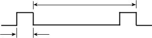
ThePike 2 LSI on the master drive provides the reference signal (SSREF+). The index signal generates a 120 Hz signal. The signal is normally false/negated (nominal 0V) and makes a transition to the true/asserted (nominal +5V) level to indicate the reference position during the revolution period. Master and slave drives use the trailing (falling) edge of the reference signal to phase-lock their spindles. A maximum of 10 seconds is allowed for a slave to synchronize with the reference signal. Figure 5 shows the characteristics of the reference signal.
1.2 sec ± 0.5
1
SSREF +
0
1.0 sec min.
1.37 sec max.
T= 0.0083 seconds (± 1.0% max)
±10 microseconds cycle-to-cycle variance
±20 microseconds phase error while synchronized
Figure 5. Synchronized reference signal characteristics
SCSI interface factors
The Rotational Position Locking (RPL) field in byte 17 (bits 0 and 1) of the Rigid Disc Drive Geometry mode parameters page (page 04h) is used for enabling and disabling spindle synchronization mode (see the SCSI-2 Interface Product Manual). If the target fails to synchronize, it creates a unit attention condition to all initiators.The sense key is set to Unit Attention and the additional sense code is set to Spindle Synchronized (5C01).
After reaching synchronization, if the target detects a change of synchronization and:
1.If the logical unit is not executing an I/O process for the initiator, then the target creates a unit attention condition. The sense key is set to Unit Attention and the additional sense code is set to Spindle Synchronized (5C01) or Spindle Not Synchronized (5C02).
2.If the logical unit is executing an I/O process and no other error occurs, then the target returns Check Condition status. The sense key is set to Recovered Error if the target is able to complete the I/O process or to Hardware Error if the target is unable to complete the I/O process. The additional sense code is set to Spindle Synchronized (5C01) or Spindle Not Synchronized (5C02).
Barracuda 2LP Product Manual, Rev. D |
19 |
You may operate the drive with a rotational skew when synchronized. The rotational skew is applied in the retarded direction (lagging the synchronizedspindle master control). A rotational offset of up to 255/256 of a revolution lagging may be selected. Select the amount of offset by using the Mode Select command, Rigid Disc Drive Geometry page (page 04h), byte 18(see the SCSI-2 Interface Product Manual). The value in byte 18 (0–FFh) is the numerator of a fractional multiplier that has 256 as the denominator. For example, 40h selects 40h/FFh or 1/4 of a revolution lagging skew, 80h selects 1/2 of a revolution lagging skew, etc. Since the drive supports all offset values from 0 to 255, values sent by the initiator are not rounded off. The drive’s translation of the digital offset values to physical rotational offsets results in offset values whose phase error lies within the ± 20 microseconds phase error with respect to the supplied 120 Hz reference signal.
The drive does not have the capability to adjust the rotational offset value requested by the initiator to a physical offset in the drive that corresponds in any way to sector boundaries or changes in ZBR zones. The initiator must formulate these boundaries or changes, if required, to calculate the value of offset it sends to the drive.
20 |
Barracuda 2LP Product Manual, Rev. D |
|
|
 Loading...