


Seagate ST12400N, ST11900NC, ST11900ND, ST11900N, ST12400NC Manual
.... . . . . . . . . . . . . . . . . . . . . . . . . . . . . . . . . . . . . . . . . . . . . . . . . . . . . . . .
Hawk 2 Family:
. . . . . . . . . . . . . . . . . . . . . . . . . . . . . . . . . . . . . . . . . . . . . . . . . . . . . . . .
ST12400N/ND/NC
. . . . . . . . . . . . . . . . . . . . . . . . . . . . . . . . . . . . . . . . . . . . . . . . . . . . . . . .
ST11900N/ND/NC
. . . . . . . . . . . . . . . . . . . . . . . . . . . . . . . . . . . . . . . . . . . . . . . . . . . . . . . .
. . . . . . . . . . . . . . . . . . . . . . . . . . . . . . . . . . . . . . . . . . . . . . . . . . . . . . . .
Product Manual, Volume 1
. . . . . . . . . . . . . . . . . . . . . . . . . . . . . . . . . . . . . . . . . . . . . . . . . . . . . . . .

. . . . . . . . . . . . . . . . . . . . . . . . . . . . . . . . . . . . . . . . . . . . . . . . . . . . . . . . .
Hawk 2 Family:
. . . . . . . . . . . . . . . . . . . . . . . . . . . . . . . . . . . . . . . . . . . . . . . . . . . . . . . . .
ST12400N/ND/NC
. . . . . . . . . . . . . . . . . . . . . . . . . . . . . . . . . . . . . . . . . . . . . . . . . . . . . . . . .
ST11900N/ND/NC
. . . . . . . . . . . . . . . . . . . . . . . . . . . . . . . . . . . . . . . . . . . . . . . . . . . . . . . . .
. . . . . . . . . . . . . . . . . . . . . . . . . . . . . . . . . . . . . . . . . . . . . . . . . . . . . . . . .
Product Manual, Volume 1
. . . . . . . . . . . . . . . . . . . . . . . . . . . . . . . . . . . . . . . . . . . . . . . . . . . . . . . . .
ã 1995 Seagate Technology, Inc. All rights reserved Publication Number: 77767450, Revision E
March 1995
Seagateâ, Seagate Technologyâ and the Seagate logo are registered trademarks of Seagate Technology, Inc. Hawk™, SeaFAX ä, SeaFoneä, SeaTDDä and SeaBOARDä are trademarks of Seagate Technology, Inc. Other product names are registered trademarks or trademarks of their owners.
Seagate reserves the right to change, without notice, product offerings or specifications. No part of this publication may be reproduced in any form without written permission of Seagate Technology, Inc.
Product Manual - Hawk 2 Family SCSI-2 (Volume 1), Rev. E v
_________________________________________________________________________________________
|
|
Revision status summary sheet |
|
||
Revision |
Authority |
Date |
Writer/Eng. |
|
Sheets Affected |
A Issue |
|
9/27/93 |
D. Ashby |
|
v thru viii, 1 thru 71. |
B |
PLD: 84283 |
94 Mar 07 |
SS |
|
v thru viii, 1 thru 71. |
|
|
|
|
|
(technical changes pages 46, 47, |
|
|
|
|
|
52, 53 and 54.) |
C |
PLD: 84224 |
5/26/94 |
SS |
v, vi, 6, 8, 11, 12, 15, 16, 21, 23, 24, 25, |
|
|
|
|
|
29, 30, 31, 34, 35, 37, 46, 47, 51 - 54, |
|
|
|
|
|
56, 60, 64. |
|
D |
PLD: 84392 |
6/14/94 |
D. Ashby |
|
v, 2, 14 and 26. |
E |
PLD: 84542 |
03/17/95 |
J. Rust/J. Bentley |
v, 24, 25, 69, 70, 71 |
|
Notice.
Product Manual 77767450 is Volume 1 of a two Volume document with the SCSI interface information in the Volume 2 SCSI Interface Product Manual, P/N 77738479.
If the SCSI Interface information is needed theVolume 2 Interface Manual should be ordered, P/N 77738479.
vi Product Manual - Hawk 2 Family SCSI-2 (Volume 1), Rev. C
________________________________________________________________________________________
|
|
Table of contents |
|
1.0 |
Scope |
........................................................................................................................................... |
1 |
2.0 |
Applicable ...............................................................standards and reference documentation |
2 |
|
|
2.1 ........................................................................................................................ |
Standards |
2 |
|
2.2 ...................................................................................... |
Applicable reference documents |
2 |
3.0 |
General ....................................................................................................................description |
3 |
|
4.0 |
Standards .....................................................................................................................features |
5 |
|
|
4.1. .................................................................................................................... |
Performance |
5 |
|
............................................................................................................ |
4.1.1 Reliability |
5 |
|
4.2 ............................................................................. |
Unformatted and formatted capacities |
6 |
|
4.3 ................................................................................................ |
Options (factory installed) |
6 |
|
4.4 ............................................................................... |
Optional accessories (user installed) |
6 |
|
4.5 ........................................................................................................................ |
Installation |
7 |
5.0 |
Performance ......................................................................................................characteristics |
8 |
|
|
5.1 ........................................................... |
Internal drive characteristics (transparent to user) |
8 |
|
5.2 ............. |
SCSI drive Seek, Read and Write performance characteristics (Visible to User) |
8 |
|
........................................................................... |
5.2.1 Seek command execution time |
8 |
|
............................................................... |
5.2.2 Format drive command execution time |
9 |
|
................................................................... |
5.2.3 Read data command execution time |
9 |
|
................................................................... |
5.2.4 Write data command execution time |
9 |
|
5.3 ........................................................................ |
Generalized performance characteristics |
10 |
|
............................................................................ |
5.3.1 Notes for sections 5.2 and 5.3 |
11 |
5.4Start/stop time 11
|
5.5 |
Prefetch/multi segmented cache control .......................................................................... |
12 |
|
|
|
5.5.1 |
Cache operation .................................................................................................. |
12 |
|
|
5.5.2 |
Prefetch operation ............................................................................................... |
13 |
|
5.6 |
Caching write data ........................................................................................................... |
14 |
|
|
5.7 |
Synchronized spindle operation ....................................................................................... |
14 |
|
6.0 |
Reliability specifications ............................................................................................................ |
18 |
||
|
6.1 |
Error rates ........................................................................................................................ |
18 |
|
|
|
6.1.1 |
Read errors ....................................................................................................... |
18 |
|
|
6.1.2 |
Environmental interference ................................................................................ |
18 |
|
|
6.1.3 |
Write errors ....................................................................................................... |
19 |
|
|
6.1.4 |
Seek errors ........................................................................................................ |
19 |
|
6.2 |
Reliability and service ...................................................................................................... |
19 |
|
|
|
6.2.1 |
Mean time between failure................................................................................. |
19 |
|
|
6.2.2 |
Preventive maintenance .................................................................................... |
19 |
|
|
6.2.3 |
Service life ......................................................................................................... |
19 |
|
|
6.2.4 |
Service philosophy ............................................................................................ |
20 |
|
|
6.2.5 |
Installation ......................................................................................................... |
20 |
|
|
6.2.6 |
Service tools ...................................................................................................... |
20 |
|
|
6.2.7 |
Product Warranty............................................................................................... |
20 |
Product Manual - Hawk 2 Family SCSI-2 (Volume 1), Rev. B vii
_________________________________________________________________________________________
|
|
|
Table of contents |
|
7.0 |
Physical/electrical specifications .............................................................................................. |
21 |
||
|
7.1 |
AC power requirements ................................................................................................... |
21 |
|
|
7.2 |
DC power requirements ................................................................................................... |
21 |
|
|
|
7.2.1 |
Conducted noise immunity ................................................................................ |
22 |
|
|
7.2.2 |
Power sequencing ............................................................................................. |
22 |
|
|
7.2.3 |
12 V - current profile .......................................................................................... |
22 |
|
7.3 |
Heat/power dissipation ..................................................................................................... |
23 |
|
|
7.4 |
Environmental limits ......................................................................................................... |
23 |
|
|
|
7.4.1 |
Temperature ...................................................................................................... |
24 |
|
|
7.4.2 |
Relative humidity ............................................................................................... |
26 |
|
|
7.4.3 |
Effective altitude (sea level ref) .......................................................................... |
26 |
|
|
7.4.4 |
Shock and vibration ........................................................................................... |
26 |
|
|
7.4.5 |
Air cleanliness ................................................................................................... |
28 |
|
7.5 |
Electromagnetic compatibility ........................................................................................... |
28 |
|
|
|
7.5.1 |
Electromagnetic susceptibility ........................................................................... |
28 |
|
7.6 |
Mechanical specifications ................................................................................................ |
29 |
|
|
|
7.6.1 |
Drive orientation ................................................................................................ |
31 |
|
|
7.6.2 |
Cooling .............................................................................................................. |
31 |
|
|
7.6.3 |
Drive mounting .................................................................................................. |
31 |
8.0 |
Media characteristics ................................................................................................................. |
32 |
||
|
8.1 |
Media description ............................................................................................................. |
32 |
|
9.0 |
Defect and error management ................................................................................................... |
33 |
||
|
9.1 |
Drive internal defects/errors ............................................................................................. |
33 |
|
|
9.2 |
SCSI systems error considerations .................................................................................. |
33 |
|
10.0 |
Option/configuration headers .................................................................................................... |
34 |
||
|
10.1 |
Drive ID/option select header ........................................................................................... |
34 |
|
|
10.2 |
Synchronized spindles interface ...................................................................................... |
37 |
|
|
|
10.2.1 |
electrical description .......................................................................................... |
37 |
|
10.3 |
Grounding ........................................................................................................................ |
38 |
|
11.0 |
Interface requirement ................................................................................................................. |
39 |
||
|
11.1 |
General description .......................................................................................................... |
39 |
|
|
11.2 |
SCSI interface messages supported ................................................................................ |
39 |
|
|
11.3 |
SCSI interface commands supported .............................................................................. |
40 |
|
|
|
11.3.1 |
Inquiry data ....................................................................................................... |
42 |
|
|
11.3.2 |
Mode sense data ............................................................................................... |
43 |
|
11.4 |
SCSI bus conditions and miscellaneous features supported ............................................ |
48 |
|
|
11.5 |
Synchronous data transfer ............................................................................................... |
49 |
|
|
|
11.5.1 Synchronous data transfer periods supported ................................................... |
49 |
|
|
|
11.5.2 |
REQ/ACK offset ................................................................................................ |
49 |
|
11.6 |
Physical interface ............................................................................................................. |
49 |
|
|
|
11.6.1 DC cable and connector .................................................................................... |
51 |
|
|
|
11.6.2 |
Physical characteristics ..................................................................................... |
51 |
|
|
11.6.3 |
Connector requirements .................................................................................... |
53 |
|
|
11.6.4 |
Electrical description ......................................................................................... |
60 |
|
11.7 |
Disc drive timing .............................................................................................................. |
65 |
|
viii Product Manual - Hawk 2 Family SCSI-2 (Volume 1), Rev. B
_________________________________________________________________________________________
Table of contents
12.0 |
Options ........................................................................................................................................ |
67 |
|
|
12.1 |
Front panel ....................................................................................................................... |
67 |
|
12.2 |
Single unit shipping pack ................................................................................................. |
67 |
13.0 |
Accessories ................................................................................................................................ |
68 |
|
|
13.1 |
Front panel kit .................................................................................................................. |
68 |
|
13.2 |
Installation manual ........................................................................................................... |
68 |
14.0 |
Technical support services ........................................................................................................ |
69 |
|
Seagate Peripheral Family ...................................................................................................................... |
70 |
||
Product Manual - Hawk 2 Family SCSI-2 (Volume 1), Rev. B |
1 |
_________________________________________________________________________________________
1.0Scope
This specification describes the Seagate Technology, Inc. Hawk 2 Model ST12400 Disc Drive.This high capacity, high performance member of the Seagate 3.5 inch rigid disc family has a new HDA (Head/Disc Assembly) design having improvements over previous 3.5-inch Seagate models. It has an embedded SCSI controller. Performance information is given in Section 5. The Hawk 2 Family Model ST12400 drive interface is defined for functional compatibility to a subset of the Seagate SCSI-2 Interface Specification 77738479, and the ANSI SCSI-2 standard. The Hawk 2 Family drives are classified as “Intelligent” peripherals. The Hawk 2 Family provides Level 2 conformance (highest level) with the ANSI SCSI-1 standard. Details of the Hawk 2 Family drive SCSI implementation are provided in Section 11 of this specification, (Vol. 1) and in the SCSI-2/SCSI-3 Interface Product Manual P/N 77738479 (Vol. 2; Ver. 2).
The Hawk 2 family of drives consists of the ST12400N/ND/NC and ST11900N/ND/NC drives.
From this point on in this Product Manual the reference to Hawk 2 Family is referred to as “the drive” (unless reference to individual models are necessary).
The drive printed circuit board is referred to as a PCB.
E |
|
T |
|
A |
G |
|
A |
|
E |
|
S |
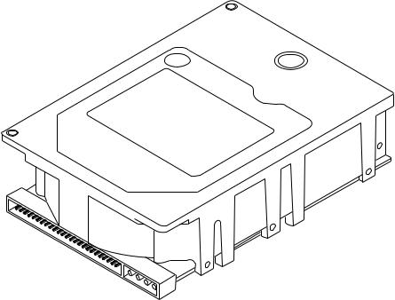
*
*50 pin SCSI I/O and 4 pin DC power connector shown. "NC" drive models have a single 80 pin connector and no separate DC power connector.
Figure 1-1. Hwk 2 family drive
2 Product Manual - Hawk 2 Family SCSI-2 (Volume 1), Rev. D
_________________________________________________________________________________________
2.0Applicable standards and reference documentation
The drive has been developed as a system peripheral to the highest standards of design and construction. The drive depends upon its host equipment to provide adequate power and environment in order to achieve optimum performance and compliance with applicable industry and governmental regulations. Special attention must be given in the areas of safety, power distribution, shielding, audible noise control, and temperature regulation. In particular, the drive must be securely mounted in order to guarantee the specified performance characteristics.
2.1Standards
The Hawk 2 Family complies with Seagate standards as noted in the appropriate sections of this specification and the Seagate SCSI-2/SCSI-3 Interface Specification, P/N 77738479 (Vol. 2, Version 2).
The Hawk 2 Family is a UL Recognized component per UL 1950 and a CSA Certified component per CAN/CSAC22.2 No. 950-M89. It also meets the requirements of DIN VDE 0805/05.90 and EN60950: 1988 (IEC 950).
The Hawk 2, as delivered, is designed for system integration and installation into a suitable enclosure prior to use. As such the Hawk 2 is supplied as a sub-assembly and is not subject to Subpart J of Part 15 of the FCC Rules and Regulations nor the Radio Interference Regulations of the Canadian Department of Communications. However, the unit has been tested using proper shielding and grounding and found to be compliant with Class A limits of the FCC Rules and the Regulations of The Canadian Department of Communications.
The physical design characteristics of the Hawk 2 serve to minimize radiation when installed in an enclosure that provides reasonable shielding. As such, the Hawk 2 is capable of meeting the Class B limits of the FCC Rules and Regulations of the Canadian Department of Communication. However, it is the users responsibility to assure that the Hawk 2 meets the appropriate EMI requirements in their system. Shielded I/O cables may be required if the enclosure does not provide adequate shielding. If the I/O cables are external to the enclosure, shielded cables should be used, with the shields grounded to the enclosure and to the host controller.
Caution. To avoid potential service problems, observe the following precautions:
The Manufacturers installed labels must not be removed from the drive or covered with additional labels, as they contain information required when servicing the product.
2.2Applicable reference documents
Installation Guide |
Seagate P/N 77767451 |
Product Manual - SCSI-2 Interface |
Seagate P/N 77738479 |
ANSI Small Computer System Interface (SCSI): Document Number ANSI3.131-1986 (X3T9/84.40 Rev. 1B) (X3T9.2/82-2 Rev. 17B) and X3T9.2/86-109 Revision 10H (SCSI-2).
Package Test Specification Seagate P/N 30190-001 (under 100 lb.)
Package Test Specification Seagate P/N 30191-001 (over 100 lb.)
In case of conflict between this document and any referenced document, this document shall take precedence.
Product Manual - Hawk 2 Family SCSI-2 (Volume 1), Rev. B |
3 |
________________________________________________________________________________________
3.0General description
The drives are a member of a family of low cost, high performance, highly reliable, random access storage devices designed to meet the needs of the OEM marketplace.
The drive records and recovers data on ten 3.7 inch (95 mm) fixed discs.
The drive supports the Small Computer System Interface-2 (SCSI-2) as described in the ANSI SCSI and SCSI- 2 Interface Specifications to the extent described in this product specification (Vol. 1), which defines the product performance characteristics of the Hawk 2 Family of drives, and the SCSI-2 Interface Product Manual P/N 77738479 (Vol. 2, Version 2) which describes the general interface characteristics of this and other families of Seagate 3.5- inch drives.
The drive interface supports multiple initiators, disconnect/reconnect, self configuring host software and automatic features that relieve the host from the necessity of knowing the physical characteristics of the targets (logical block addressing is used).
The Head/Disc Assembly (HDA) is environmentally sealed at the factory. Air recirculates within the HDA through a nonreplaceable filter to maintain a contamination free head/disc environment.
Refer to Figure 3.0-1 for an exploded view of the drive. NEVER disassemble the Head/Disc Assembly (HDA). This exploded view is for information only. Do not attempt to service items in the sealed environmental enclosure (heads, media, actuator, etc.) as this requires special facilities. The drive contains no parts replaceable by the user. The drive warranty is voided if the HDA is opened.
The Hawk 2 Family drives use a dedicated landing zone at the innermost radius of the media to eliminate the possibility of destroying or degrading data by landing in the data zone.The drive automatically goes to the landing zone when the power is removed.
The Hawk 2 Family drives incorporate an automatic shipping lock which prevents potential damage to the heads and discs that result from movement during shipping and handling. The shipping lock disengages when power is applied to the drive and the head load process begins.
The Hawk 2 Family drives decode Track 0 location from the dedicated servo surface to eliminate mechanical transducer adjustments and related reliability concerns.
The Hawk 2 Family drives use a high performance actuator assembly that consists of a low inertia, balanced, patented, straight arm design that provides excellent performance with minimum power dissipation.

4 Product Manual - Hawk 2 Family SCSI-2 (Volume 1), Rev. B
_________________________________________________________________________________________
ST12400N/ND |
ST12400NC |
Family PCB |
Family PCB |
Figure 3.0-1. Hawk 2 family drive
Product Manual - Hawk 2 Family SCSI-2 (Volume 1), Rev. B |
5 |
________________________________________________________________________________________
4.0Standard features
The Hawk 2 Family has the following standard features:
∙Integrated SCSI Controller
∙Single Ended and Differential SCSI drivers and receivers
∙Asynchronous and Synchronous data transfer protocol
∙Firmware downloadable via SCSI interface
∙Selectable sector size from 256 to 4096 bytes/sector
∙Programmable sector reallocation scheme
∙Flawed sector reallocation at format time
∙Programmable auto write and read reallocation
∙Reallocation of defects on command (Post Format)
∙96 bit Reed-Solomon error correcting code
∙Sealed Head/Disc Assembly
∙No preventative maintenance or adjustment required
∙Dedicated head landing zone
∙Automatic shipping lock
∙Automatic Thermal Compensation
∙Patented Tri-Phase Servo with embedded Grey Code track address to guarantee servo positioning.
∙Self diagnostics performed at power on
∙1:1 Interleave
∙Zoned Bit Recording (ZBR)
∙Vertical, horizontal, or top down mounting
∙Dynamic spindle brake
∙Synchronous spindle capability
∙256 K byte data buffer (Optional 1 MB available)
∙Permanently mounted terminators (for model ST12400N only), enabled by installation of a jumper plug.
4.1Performance
∙Programmable multi-segmentable cache buffer
∙5411 RPM Spindle. Average latency = 5.54 ms
∙Command Queuing of up to 64 commands per initiator
∙Background processing of queue
∙Supports start and stop commands
∙Provides synchronized spindle capability
∙Low audible noise for office environment
∙Low power consumption
4.1.1Reliability
∙500,000 hour MTBF
∙Adaptive seek velocity. Improved seek performance
∙LSI circuitry
∙Balanced low mass rotary voice coil actuator
∙5 year warranty

6 Product Manual - Hawk 2 Family SCSI-2 (Volume 1), Rev. C
_________________________________________________________________________________________
4.2Unformatted and formatted capacities
Formatted capacity depends on the number of spare reallocation sectors reserved and the number of bytes per sector. The following table shows some typical formatted capacities.
Spare Sectors or Cylinders |
ST12400N/ND/NC |
ST11900N/ND/NC |
||
Reserved for reallocation |
512[1] |
1024[1] |
512[1] |
1024[1] |
|
MB |
|
MB |
|
No Spares |
2165 |
2279 |
1709 |
1799 |
12 Spare Sectors Per Cylinder [2] |
|
|
|
|
2 Spare Cylinders per Unit [3] |
2148 |
2245 |
1700 |
1758 |
One Spare Sector per Cylinder |
|
|
|
|
2 Spare Cyl. per Unit [3] |
2162 |
2275 |
1707 |
1795 |
Unformatted Capacity |
2537 |
|
2003 |
|
|
|
|
|
|
Notes.
[1]Bytes per sector. Sector size selectable at format time. Users having the necessary equipment may modify the data block size before issuing a format command and obtain different formatted capacities than those listed. User available capacity depends on spare reallocation scheme selected. See Mode Select Command and Format Command in the SCSI Interface Product Manual P/N 77738479.
[2]Twelve spare sectors are on one track. ST11900 has 6 spare sectors per cylinder.
[3]Spare cylinders are on the inner tracks.
The standard OEM model is as follows:
|
Formatted Data Block Size* |
Unformatted |
|
512 Byte/Sector |
|
ST12400N/ND/NC |
2148 MB |
2537 MB |
ST11900N/ND/NC |
1700 MB |
2003 MB |
*Twelve spare sectors per cylinder, two spare cylinders/unit for ST12400 Six spare sectors per cylinder, two spare cylinders/unit for ST11900
4.3Options (factory installed)
The capacities shown in paragraph 4.2 are available upon request. Other capacities can be ordered depending on sparing scheme and sector size requested.
The following options are incorporated at the time of production. See Section 12.0.
∙Front panel (green LED) - See Figure 3.0-1
∙Installation Manual P/N 77767451
4.4Optional accessories (user installed)
The following accessories are available. All kits may be installed in the field. See Section 13.0.
∙Front Panel Kit (with green LED) - See Figure 3.0-1
∙Single Unit shipping pack kit
∙Installation Guide P/N 77767451
∙Adapter Accessory Frame Kit P/N 75790701 (adapts 3.5-inch drive to fit in 5.25-inch drive mounting space)
Product Manual - Hawk 2 Family SCSI-2 (Volume 1), Rev. B |
7 |
_________________________________________________________________________________________
4.5Installation
For option jumper locations and definitions refer to Figure 10.1-1. Drive default mode parameters are not normally needed for installation. Refer to Section 11.3.2 for default mode parameters if they are needed.
∙Ensure that the SCSI ID of the drive is not the same as the host adapter. Most host adapters use SCSI ID 7.
∙If multiple devices are on the bus set the drive SCSI ID to one that is not presently used by other devices on the bus.
∙If the drive is the only device on the bus, attach it to the end of the SCSI bus cable. Permanently installed terminators must be enabled on the drive for ST12400N models using a jumper plug (see Figure 10.1-1), For ST12400ND models, terminators must be installed external to the drive. These external terminators must be provided by the user, systems integrator or host equipment manufacturer.
∙If the drive is attached to a bus that contains other devices, and the new drive is not attached to the end of the bus, the terminator enable jumper should be removed from the new drive.
∙Set all appropriate option jumpers for desired operation prior to power on. If jumpers are changed after power has been applied, recycle the drive power to make the new settings effective.
Installation instructions are provided by host system documentation or with any additionally purchased drive installation software. If necessary see section 14.0 for Seagate support services telephone numbers.
Formatting
∙It is not necessary to low level format this drive. The drive is shipped from the factory low level formatted in 512 byte sectors.
∙Reformat the drive if one of the following occurs.
-A different sector size is selected.
-A different spare sector allocation scheme is selected.
8 Product Manual - Hawk 2 Family SCSI-2 (Volume 1), Rev. C
_________________________________________________________________________________________
5.0Performance characteristics
5.1Internal drive characteristics (transparent to user)
|
|
ST12400N/ND/NC |
ST11900N/ND/NC |
|
Drive Capacity |
2537 |
2003 |
MByte (UNF) |
|
Read/Write Heads |
19 |
15 |
Data (Max) |
|
Bytes/Track |
|
50,945 |
50,945 |
Bytes (Avg) |
Bytes/Surface |
131.3 |
131.3 |
Mbytes (UNF) |
|
Tracks/Surface, Total |
2621 |
2621 |
Tracks (user |
|
|
|
|
|
accessible) |
Tracks/Inch |
|
3000 |
3000 |
TPI |
Servo Heads |
1 |
1 |
|
|
Internal Data Rate |
26.8 to 45.6 |
26.8 to 45.6 |
Mbits/sec |
|
|
|
|
|
(variable with |
|
|
|
|
zone) |
Disc Rotational Speed |
5411 +0.5% |
5411 +0.5% |
r/min |
|
Average Rotational Latency |
5.54 |
5.54 |
ms |
|
5.2 |
SCSI Seek, Read and Write performance characteristics |
(visible to user) [8] |
||
Refer to Section 11.7 and to the SCSI-2 Interface Product Manual 77738479 for additional timing details.
5.2.1Seek time
|
|
|
|
|
Drive Level |
|
|
|
|
|
|
ST12400N/ND/NC |
ST11900N/ND/NC |
||
|
|
|
|
Read |
Write |
Read |
Write |
|
|
|
|
|
ms |
|
ms |
Average |
- |
Typical |
[3]* |
9.3 |
10.8 |
9.3 |
10.8 |
|
|
Max. |
[2] |
11.1 |
12.6 |
11.1 |
12.6 |
Single Track |
- |
Typical |
[3] |
1.0 |
1.7 |
1.0 |
1.7 |
|
|
Max. |
[2] |
1.5 |
2.0 |
1.5 |
2.0 |
Full Stroke |
- |
Typical |
[3] |
21.0 |
22.5 |
21.0 |
22.5 |
|
|
Max. |
[2] |
23.0 |
24.0 |
23.0 |
24.0 |
|
|
|
|
Including Controller Overhead |
|
||
|
|
|
|
(without disconnect) |
[1] [4] |
|
|
|
|
|
|
ST12400N/ND/NC |
ST11900N/ND/NC |
||
|
|
|
|
Read |
Write |
Read |
Write |
|
|
|
|
|
ms |
ms |
|
Average |
- |
Typical |
[3] |
10.3 |
11.8 |
10.3 |
11.8 |
|
|
Max. |
[2] |
12.1 |
13.6 |
12.1 |
13.6 |
Single Track |
- |
Typical |
[3] |
2.0 |
2.7 |
2.0 |
2.7 |
|
|
Max. |
[2] |
2.5 |
4.0 |
2.5 |
4.0 |
Full Stroke |
- |
Typical |
[3] |
22.0 |
23.5 |
22.0 |
23.5 |
|
|
Max. |
[2] |
24.0 |
25.0 |
24.0 |
25.0 |
Product Manual - Hawk 2 Family SCSI-2 (Volume 1), Rev. B |
9 |
_________________________________________________________________________________________
5.2.2Format drive command execution time (minutes) [1]
|
ST12400N/ND/NC |
ST11900N/ND/NC |
Maximum (with verify) |
45 Min. |
37 Min |
Maximum (no verify) |
31 Min. |
27 Min. |
*[ ] All notes are listed in Section 5.3.1. |
|
|
5.2.3Read data command execution time [4]
(512 byte sector size, without disconnect and with read look ahead cache disabled). latency time is included.
a. From CDB reception to the drive request for the first data byte to be transferred to the Host
1. |
Typical (Zero Stroke Seek) |
7.32 ms [3]* |
2. |
Typical (Average Seek) |
16.84 ms [3] |
3. |
Maximum (Full Stroke Seek) |
31.38 ms [2] |
b.Single Sector Read and Transfer of data to Host (time from receipt of last byte of the CDB to the request for a status byte transfer to Host) [7].
1. |
Typical (Zero Stroke Seek) |
7.42 ms [3] |
2. |
Typical (Average Seek) |
16.95 ms [3] |
3. |
Maximum (Full Stroke Seek) |
31.49 ms [2] |
5.2.4Write data command execution time [4]
(512 byte sector size, without disconnect and with read look ahead disabled) latency time is included.
a. From CDB reception to the request for the first byte of write data from the Host. 1. Typical 1.49 ms 2. Maximum 1.61 ms
b.Single Sector Write and Data Transfer from Host [7] [6]
(Time from receipt of the last byte of the CDB to the request for a completion status transfer to the Host)
1. |
Typical (Zero Stroke Seek) |
7.72 ms [3] |
2. |
Typical (Average Seek) |
17.10 ms [3] |
3. |
Maximum (Full Stroke Seek) |
31.93 ms [2] |
*[ ] All notes are listed in Section 5.3.1.
10 Product Manual - Hawk 2 Family SCSI-2 (Volume 1), Rev. B
_________________________________________________________________________________________
5.3Generalized performance characteristics
Minimum Sector Interleave |
1 to 1 |
Data Buffer To/From Disc Media
Data transfer rate (< 1 sector) - 512 Byte Sector
Min. [4]* |
3.35 MByte/sec |
Avg. [4] |
4.59 MByte/sec |
Max. [4] |
5.35 MByte/sec |
Data Buffer To/From Disc Media
Data Transfer Rate (< 1 Track) - 512 Byte Sector
Min. [4] 2.88 MByte/sec divided by (Interleave Factor)
Avg. [4] 3.94 MByte/sec divided by (Interleave Factor)
Max. [4] 4.6 Mbyte/sec divided by (Interleave Factor)
SCSI Interface Data |
|
|
|
|
|
Transfer Rate (Asynchronous) [5] |
|
|
|
|
|
|
ST12400N/NC/ST11900N/NC |
ST12400ND/ST11900ND |
|||
-Maximum Instantaneous |
** |
5.2 MBytes/sec |
|
3.3 MBytes/sec |
|
-Maximum Average |
*** |
3.1 MBytes/sec |
|
2.4 MBytes/sec |
|
Sector Sizes 512 user data blocks (default) |
|
|
|
||
Variable (256 to 4096) in even sector sizes |
|
|
|
||
Synchronous Transfer Rate |
|
|
|
|
|
From 1.25 MByte/sec to 10.0 MBytes/sec (See section 11.5.) |
|
|
|
||
Read/Write consecutive sectors on a track |
|
|
|
Yes |
|
Flaw reallocation performance impact (For flaws reallocated using the spare |
|
Negligible |
|||
sectors per track reallocation scheme.) |
|
|
|
|
|
Flaw reallocation performance impact (For flaws reallocated using the spare |
|
Negligible |
|||
sectors per cylinder reallocation scheme.) |
|
|
|
|
|
Flaw reallocation performance impact (For flaws reallocated using the spare tracks |
35 ms (typical) |
||||
per volume reallocation scheme.) |
|
|
|
|
|
Overhead time for head switch (512 byte sectors) |
|
|
1 ms |
||
Overhead time for one track cylinder switch |
|
|
|
<3 ms Typical |
|
Average rotational latency |
|
|
|
|
5.54 ms |
*[ ] All notes are listed in Section 5.3.1.
**Assumes system ability to support 5.2 Mb/s and no cable loss.
***Assumes typical host delays and cable losses.
Product Manual - Hawk 2 Family SCSI-2 (Volume 1), Rev. C |
11 |
_________________________________________________________________________________________
5.3.1Notes for sections 5.2 and 5.3.
[1]Execution time measured from receipt of the last Byte of the Command Descriptor Block (CDB) to the request for a Status Byte Transfer to the Initiator (excluding connect/disconnect).
[2]Maximum times are specified over the worst case conditions of temperature, voltage margins and drive orientation. When comparing specified seek times, care should be taken to distinguish between typical seek times and maximum seek times. The best comparison is obtained by system benchmark tests conducted under identical conditions. Maximum times do not include error recovery.
[3]Typical Seek values are measured under nominal conditions of temperature, voltage, and horizontal orientation as measured on a representative sample of drives.
[4]Assumes no errors and no sector has been relocated.
[5]Rate measured from the start of the first sector transfer to or from the Host.
[6]Assumes the Initiator immediately sends Write Data to the drive when requested.
[7]Command execution requires a data transfer phase (data to or from the disc media). Assumes the initiator is instantly ready to send/receive the data when the drive generates first request for a data byte transfer, and assumes an average data transfer rate between the drive and the Initiator as specified in section 5.3.
[8]All performance characteristics assume that automatic adaptive temperature compensation is not in process when the SCSI command is received. A SCSI command being executed is not interrupted for automatic adaptive temperature compensation. If adaptive thermal compensation is in process when a SCSI command is received, the command is queued until the compensation for the specific head being compensated completes. When compensation completes for the specific head being compensated, the first queued SCSI command is executed. When execution of the first queued command is complete, the drive continues the compensation for the remaining head(s). The above procedure continues until compensation for all heads is completed, or until one minute has elapsed. If the compensation for all heads is not complete in one minute, the drive performs compensation for all of the remaining heads sequentially without any interruption. The drive initiates an automatic adaptive temperature compensation cycle approximately one minute after poweron, and approximately once every 10 minutes thereafter. Automatic adaptive temperature compensation takes less than 0.1% of bus time. Automatic temperature compensation also occurs at other times, but should be transparent to the user (e.g., during format, Rezero Command, at spindle up, during read error recovery, and during Reassign Block functions). A Rezero command can be used to reset the thermal compensation timer back to its start so that the host can know when the interruption for thermal compensation will occur.
5.4Start/stop time
After DC power has been applied, the drive becomes ready within 25 seconds if the Motor Start Option is disabled (i.e. the motor starts as soon as the power has been applied). During this time the drive responds to some commands over the SCSI interface*. Stop time is less than 20 seconds from removal of DC power.
12 Product Manual - Hawk 2 Family SCSI-2 (Volume 1), Rev. C
_________________________________________________________________________________________
If the Motor Start Option is enabled the internal controller accepts the commands listed in the SCSI Interface Product Manual* less than 3 seconds after DC power has been applied. After the Motor Start Command has been received the drive becomes ready for normal operations within 25 seconds. The Motor Start Command can also be used to command the drive to stop the spindle*.
There is no power control switch on the drive.
5.5Prefetch/multi-segmented cache control
The drive provides prefetch (read look-ahead) and multi-segmented cache control algorithms that in many cases can enhance system performance. “Cache” as used herein refers to the drive buffer storage space when it is used in “cache” operations.To select prefetch and cache features the host sends the Mode Select command with the proper values in the applicable bytes in Mode Page 08h*. Prefetch and cache operation are independent features from the standpoint that each is enabled and disabled independently via the Mode Select command. However, in actual operation the prefetch feature overlaps cache operation somewhat as is noted in sections 5.5.1 and 5.5.2.
All default cache and prefetch Mode parameter values (Mode Page 08h) for standard OEM versions of this drive family are given in Tables 11.3.2-1 through 11.3.2-4.
5.5.1Cache operation
In general, 240 Kbytes of the 256 Kbytes of physical buffer space in the drive can be used as storage space for cache operations (984 Kbytes of 1 MB for drives having the optional 1 MB buffer). The buffer can be divided into logical segments (Mode Select Page 08h, byte 13) from which data is read and to which data is written. The drive maintains a table of logical block disk medium addresses of the data stored in each segment of the buffer. If cache operation is enabled (RCD bit = 0 in Mode Page 08h, byte 2, bit 0. See SCSI Interface Product Manual*), data requested by the host with a Read command is retrieved from the buffer (if it is there), before any disc access is initiated. If cache operation is not enabled, the buffer (still segmented with required number of segments) is still used, but only as circular buffer segments during disc medium read operations (disregarding Prefetch operation for the moment). That is, the drive does not check in the buffer segments for the requested read data, but goes directly to the medium to retrieve it. The retrieved data merely passes through some buffer segment on the way to the host. All data transfers to the host are in accordance with “buffer-full” ratio rules. See explanations associated with Mod page 02h (disconnect/reconnect control) in the SCSI Interface Product Manual*.
The following is a simplified description of a read operation with cache operation enabled:
Case A - A Read command is received and the first logical block (LB) is already in cache:
1.Drive transfers to the initiator the first LB requested plus all subsequent contiguous LB’s that are already in the cache. This data may be in multiple segments.
2.When the requested LB is reached that is not in any cache segment, the drive fetches it and any remaining requested LB’s from the disc and puts them in a segment of the cache. The drive transfers the remaining requested LB’s from the cache to the host in accordance with the disconnect/reconnect specification mentioned above.
3.If the prefetch feature is enabled, refer to section 5.5.2 for operation from this point.
_________
*SCSI Interface Product Manual P/N 77738479.
Product Manual - Hawk 2 Family SCSI-2 (Volume 1), Rev. B |
13 |
________________________________________________________________________________________
Case B - A Read command requests data, the first LB of which is not in any segment of the cache:
1.The drive fetches the requested LB’s from the disc and transfers them into a segment, and from there to the host in accordance with the disconnect/reconnect specification referred to in case A.
2.If the prefetch feature is enabled, refer to section 5.5.2 for operation from this point.
Each buffer segment is actually a self-contained circular storage (wrap-around occurs), the length of which is an integer number of disc medium sectors. The wrap-around capability of the individual segments greatly enhances the buffer’s overall performance as a cache storage, allowing a wide range of user selectable configurations, which includes their use in the prefetch operation (if enabled), even when cache operation is disabled (see section 5.5.2). For the Hawk 2 family the number of segments may be selected using the Mode Select command, but the size can not be directly selected. Size is selected only as a by-product of selecting the segment number specification. The size in Kbytes of each segment is reported by the Mode Sense command page 08h, bytes 14 and 15. If a size specification is sent by the host in a Mode Select command (bytes 14 and 15) no new segment size is set up by the drive, and if the “STRICT” bit in Mode page 00h (byte 2, bit 1) is set to one, the drive responds as it does for any attempt to change unchangeable parameters (see SCSI I/O Product Manual*). The Hawk 2 family of drives supports operation of any integer number of segments from 1 to 16. Divide the 245,760 bytes (1,007,616 bytes for the optional 1 MB buffer) in the buffer by the number of segments to get the size (in bytes) of each segment.
5.5.2Prefetch operation
If the Prefetch feature is enabled, data in contiguous logical blocks on the disc immediately beyond that which was requested by a Read command can be retrieved and stored in the buffer for immediate transfer from the buffer to the host on subsequent Read commands that request those logical blocks (this is true even if “cache” operation is disabled). Though the prefetch operation uses the buffer as a “cache”, finding the requested data in the buffer is a prefetch “hit”, not a “cache” operation “hit”. Prefetch is enabled using Mode Select page 08h, byte 12, bit 5 (Disable Read Ahead - DRA bit). DRA bit = 0 enables prefetch. Since data that is prefetched replaces data already in some buffer segment(s), the host can limit the amount of prefetch data to optimize system performance. The drive never prefetches more logical blocks than the number specified in the prefetch logical blocks ceiling bytes (8 and 9) of Mode page 08h.
During a prefetch operation, the drive crosses a cylinder boundary to fetch more data only if the Discontinuity (DISC) bit is set to one in bit 4 of byte 2 of Mode parameters page 08h.
The operation of the prefetch feature (when enabled by DRA = 0) can be modified to an adaptable prefetch mode, wherein prefetch is disabled as long as two sequential read operations are not for contiguous blocks of data. If two sequential Read operations request contiguous logical blocks of data, the drive automatically enables the prefetch feature for the end of the second Read operation. As long as sequential Read operations request contiguous LB’s of data, prefetch operation remains enabled.
If the host uses software interleave, there will not likely ever be two sequential Read operations for contiguous LB’s, so the adaptive prefetch feature keeps prefetch disabled, even if the DRA bit enables it. Adaptive prefetch is enabled when the IC (Initiator Control) bit (Mode page 08h, byte 2, bit 7) is set to 0 and when DRA. = 0 (prefetch enabled).
__________
*SCSI Interface Product Manual, P/N 77738479.
14 Product Manual - Hawk 2 Family SCSI-2 (Volume 1), Rev. D
_________________________________________________________________________________________
5.6Caching write data
Write caching is a write operation by the drive that makes use of a drive buffer storage area where the data to be written to the medium is stored in one or more segments while the drive performs the write command.
Write caching is enabled along with read caching. For write caching, the same buffer space and segmentation is used as set up for read functions. The buffer segmentation scheme is set up or changed independently, having nothing to do with whether or not read and write caching is enabled or disabled. When a write command is issued, the cache is first checked to see if any logical blocks that are to be written are already stored in the cache from a previous read or write command. If there are, the respective cache segments are cleared. The new data is cached for subsequent Read commands.
If the number of write data logical blocks exceeds the size of the segment being written into when the end of the segment is reached, the data is written into the beginning of the same cache segment, overwriting the data that was written there at the beginning of the operation. However, the drive does not overwrite data that has not yet been written to the medium.
Tables 11.3.2-1 through 11.3.2-4 show Mode default settings for the Hawk 2 family of drives.
5.7Synchronized spindle operation
The synchronized spindles operation allows several drives operating from the same host to operate their spindles at the same synchronized rotational rate. Drives operating in a system in synchronized mode can increase the system capacity and transfer rate in a cost effective manner.
For Hawk 2 models the interface consists of a twisted pair cable that connects the drives in the synchronized system in a daisy-chain configuration as shown in Figure 5.7-1. For models "NC", the reference index signal (SYNC) signal is on pin J1-37 of the 80-pin I/O connector. Master/Slave operation is autoarbitrated by each drive after head load. Alternatively, each drive in the system can be configured by the host (using the Mode Select command Rigid Disc Drive Geometry page*) to operate in either the master or slave mode.
After loading heads, a drive autoarbitrates for occurrences of the Reference Index Signal (REFIND+). If the drive detects no REFIND+ signal on the line, it assumes master status and begins generating the REFIND+ signal. This signal will not be visible on the line until the last drive has powered up, since any unpowered drive holds the line low.
Using Mode Select command, drives can be re-configured by the host to be master or slave any time after the last drive has powered up.The master provides the reference signal to which all other drives phase lock, including the master. The master can be a drive or the host computer. All the drives may be configured as slaves, allowing the host to provide the REFIND+ signal. All drives default to the synchronized mode when power up, unless J6 pins 5 and 6 are jumpered.
Each drive can be configured (jumpered for the non-synchronized mode in which it ignores any reference signal that might be present. The connection of the synchronized reference signal to the host is required only if the host is to provide the reference signal. If the host does not provide the reference signal, the host should not be connected.
__________
*SCSI Interface Product Manual P/N 77738479.

Product Manual - Hawk 2 Family SCSI-2 (Volume 1), Rev. C |
15 |
_________________________________________________________________________________________
|
|
|
|
Sync Interface |
|
REFIND + |
|
|
|
Master Sync |
|
|
|
|
J6 |
|
|
Source |
|
|
|
|
|
|
|
|
|
|
|
6 |
|
Bottom side of PCB |
|
|
|
Spindle |
|
||
|
|
|
|
|
|||
|
|
Host |
J1 |
|
Control |
|
|
|
|
(or other drive) |
37 |
|
|
5 |
|
|
|
|
|
[2] |
|
|
|
|
|
|
|
+5V |
|
|
|
|
|
|
|
|
R T |
[1] |
|
2 |
4 |
|
|
Drive 1 |
|
|
|
|
|
|
|
|
|
||
6 |
|
|
|
|
|
|
|
DLYIND+ |
|
SCSI Bus |
|
|
|
|
J6 |
J7 |
|
|
|
|
|||
System |
|
|
Spindle |
|
6 |
||
|
|
Interface |
|
|
|
|
|
|
|
|
|
Control |
|
|
|
|
|
|
|
|
|
|
|
32 |
|
J1 |
37 |
|
|
5 |
|
|
|
|
|
[2] |
|
|
|
|
|
|
|
+5V |
|
|
|
|
|
|
|
|
R T |
[1] |
|
|
|
|
|
Drive 2 |
|
|
|
|
J2 |
|
|
|
|
|
|
|
|
|
|
|
|
|
J6 |
|
|
|
|
|
Spindle |
|
6 |
|
|
|
|
|
|
|
|
|
|
|
|
|
Control |
|
|
|
|
|
J1 |
37 |
|
|
5 |
|
|
|
|
[2] |
|
|
|
|
|
|
|
+5V |
|
|
|
|
|
|
|
|
|
|
|
|
|
|
|
|
R |
T |
[1] |
|
|
|
|
Drive n |
|
||
|
|
|
|
|
|
||
|
J1 |
|
|
|
|
|
|
Notes.
[1]Configuration Select Header (See Figure 10.1-1 and 10.2.1-1).
[2]This connection is only available on model ST12400NC.
Figure 5.7-1. Synchronized drive interconnect diagram

16 Product Manual - Hawk 2 Family SCSI-2 (Volume 1), Rev. C
_________________________________________________________________________________________
The servo/read-write LSI on the master drive provides the reference signal (REFIND+). It is a 90.18 Hz crystal generated signal. The signal is normally false/negated (nominal 0 V) and makes a transition to the true/asserted (nominal +5V) level to indicate the reference position during the revolution period.The trailing (falling) edge of the reference signal is used by the master and the slave drives to phase lock their spindles. A maximum of 10 seconds is allowed for a slave to synchronize with the reference signal. Figure 5.7-2 shows the characteristics of the reference signal. The DLYIND+ signal (available on J7-6. See Figure 5.7-1) of each synchronized drive shall occur 85.2 µsec +20 µsec after the REFIND+ signal. Figure 5.7-2 shows the characteristics of the reference signal.
T
1
REFIND +
0
0.5 usec min.
500 usec max.
T = 0.0111 second (+/- 1.0% max); +/- 10 usec cycle to cycle variance.
Figure 5.7-2. Synchronized reference signal characteristics
Product Manual - Hawk 2 Family SCSI-2 (Volume 1), Rev. B |
17 |
_________________________________________________________________________________________
SCSI Interface Factors
The Rotational Position Locking (RPL) field in byte 17 (bits 0 and 1) of the Rigid Disc Drive Geometry mode parameters page (page 04h) is used for enabling/disabling spindle synchronization mode*. If the target fails to achieve synchronization, it shall create a unit attention to all initiators.The sense key shall be set to UNIT ATTENTION and the additional sense code set to RPL STATUS CHANGE. However, in automatic arbitration mode, UNIT ATTENTION and the RPL STATUS CHANGE is not set.
If subsequent to achieving synchronization the target detects a change of synchronization:
1)and, if the logical unit is not presently executing an I/O process for the initiator, the target shall create a unit attention condition. The sense key shall be set to UNIT ATTENTION and the additional sense code set to RPL STATUS CHANGE.
2)and, if the logical unit is presently executing an I/O process and no other error occurs, the target shall return CHECK CONDITION status. The sense key shall be set to RECOVERED ERROR if the target is able to complete the I/O process or HARDWARE ERROR if the target is unable to complete the I/O process. The additional sense code is set to RPL STATUS CHANGE.
The drive may be operated with a rotational skew when synchronized. The rotational skew is applied in the retarded direction (lagging the synchronized spindle master control). A rotational offset of up to 255/256 of a revolution lagging may be selected. The amount of offset is selected by using the Mode Select command, Rigid Disc Drive Geometry page (page 04), byte 18*. The value in byte 18 (0 - FFh) is the numerator of a fractional multiplier that has 256 as the denominator. For example, 40h selects 40h/FFh or 1/4 of a revolution lagging skew, 80h selects 1/2 revolution lagging skew and etc. Since the drive supports all offset values from 0 to 255, values sent by the initiator are not rounded off. The drive translation of the digital offset values to physical rotational offsets results in offset values whose phase error lies within the + or - 20 usec phase error with respect to the supplied 90.18 Hz reference signal.
The drive does not have the capability to adjust the rotational offset value requested by the initiator to a physical offset in the drive that corresponds in any way to sector boundaries or changes in ZBR zones. Such correspondences or changes, if required, must be formulated by the initiator in order for it to calculate the value of offset it sends to the drive.
__________
*SCSI Interface Product Manual P/N 77738479.
 Loading...