

Page 1
Application
T168 Series
The T168 series microprocessor based
thermostat/controller provides a 0-10 Vdc or 4-20 mA
control. This series controls a variety of two-pipe and
four-pipe fan coil units, air handling units, unitary
equipment, and various heating and cooling
applications.
The microprocessor combines a proportional plus
intergral control algorithm with advanced adaptive
logic. This provides control without the need for tuning
or calibrating the control algorithm in the field.
Features
T168 Series
Digital, Proportional Thermostat/Controller
General Instructions
• Digital display of set point, ambient temperature,
and operating mode
• 0-10 Vdc or 4-20 mA heat and cool outputs
• Remote setback capability from a time clock or
facility management system (contact closure)
• Auxiliary heat function
• Remote and seasonal changeover sensor
• Fahrenheit or Celsius display capability
• In two pipe mode a built-in purge cycle assists the
controller to determine if the controlling agent is
providing heating or cooling
• Line voltage cont inuous on/off or 3-speed fa n control
• Low voltage fan cycling operation with demand
output
Printed in U.S.A. 5/10 © Copyright 2010 Schneider Electric All Rights Reserved. F-27025-3
Page 2
SPECIFICATIONS
Inputs
Outputs
Environment
Power Input: 20 to 28 Vac, nominal 24 Vac. Power Consumption: 25 mA maximum at 24 Vac. Connections:
Power, Terminal strip with screw down terminals.
Control, Terminal strip with screw down terminals.
Control Signal Load (Resistive): 0-10 Vdc, Minimum 1,000 Ω. 4-20 mA, 100 - 600 Ω.
Electrical:
Thermostatic Switch Rating, 10 VA @ 24 Vac. Fan Switch Current Ratings, Refer to Table-1. Proportional Band, 2F degrees (1.1C degrees). Setpoint Adjustment Range, 50 to 90° F (10 to 32°C). Heating/cooling Changeover Deadband, 3F degrees (1.6C degrees).
Mechanical:
Display Range, 32 to 99°F (0 to 37°C) Set point Range, 50 to 90°F (10 to 32°C). Material, Rigid vinyl. Finish, Cool gray.
Temperature limits:
Shipping & Storage, -30° to 130°F (-34° to 55°C).
Operating, 32° to 130°F (0° to 55°C). Humidity: Non-condensing. Shipping Weight: 0.6 lbs (270 g). Location: NEMA Type 1.
Agency Listings
CE: Compliant.
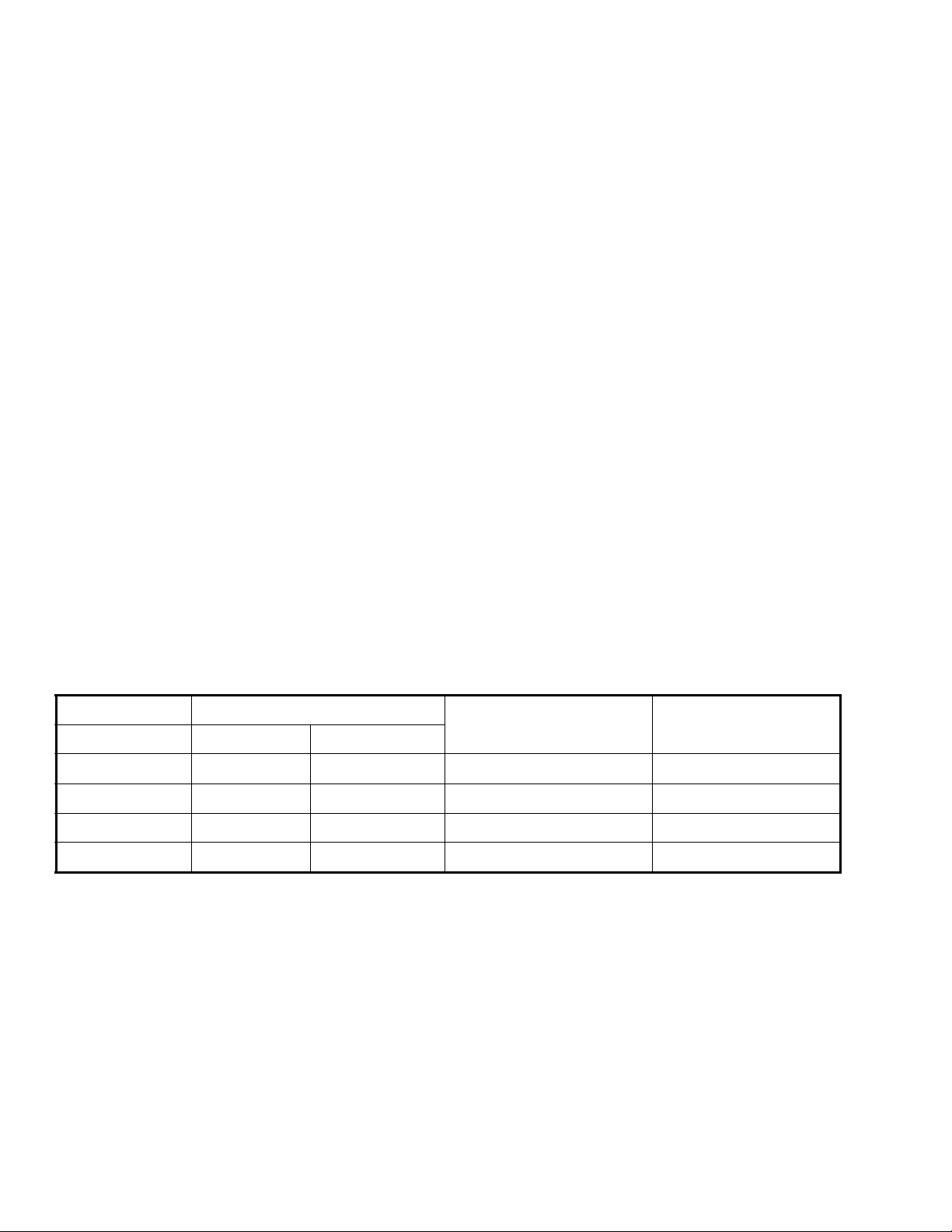
Table-1 Fan Switch Current Ratings (Amps).
Inductive
Voltage FLA LRA
24 N/A N/A N/A 24 VA
120 5.8 34.8 6.0 125 VA
240 2.9 17.4 5.0 125 VA
277 2.4 14.4 4.2 125 VA
1 When Fan Switch is off, all thermostat heat/cool and fan functions are off.
1
Resistive Amps Pilot Duty
2 © Copyright 2010 Schneider Electric All Rights Reserved. F-27025-3
Page 3

Table-2 Model Chart.
Model Outputs Fan Control Demand Output Auxiliary heat Setback System Modes
T A168-001 Dual None* No Yes Yes Off-Auto-Heat-Cool
TA168-002 Dual Off-Hi-Med-Lo Yes Yes Yes Off-Auto-Heat-Cool
TA168-003 Single Off-Hi-Med-Lo Yes No Yes Off-Heat/Off-Cool
T A168-004 Single None*
T A168-005 Single None* Yes No Yes Off-Heat/Off-Cool
T A168-006 Dual None* Yes Yes Yes Off-Auto-Heat-Cool
T A168-007 Single Off/On Yes No Yes Off-Heat/Off-Cool
T A168-008 Dual Off/On Yes No Yes Off-Auto-Heat-Cool
* Fan terminals do not exist on these models. If equipped with a demand terminal, the demand terminal is powered with 24 V on a call for heat
or cooling. The demand terminal output can be used to control a fan relay, 10 VA @ 24 Vac.
No No Yes Off-Heat/Off-Cool
Accessories
65345 4-3/4” x 4-3/4” adapter plate.
65406 Remote sensor, 60" leads 10k Ω @ 77°F (25°C).
TYPICAL APPLICATIONS (wiring diagram)
CAUTION:
• Keep all wiring at least 1-1/2 ft. (45.7 cm) away from any potential source of electrical
interference or noise.
• Do not run sensor wire parallel to line voltage wiring.
• Do not run sensor wire in conduit with line voltage.
• When low voltage or sensor wiring must intersect line voltage, cross at perpendicular
angle to minimize electrical noise.
F-27025-3 © Copyright 2010 Schneider Electric All Rights Reserved. 3
Page 4
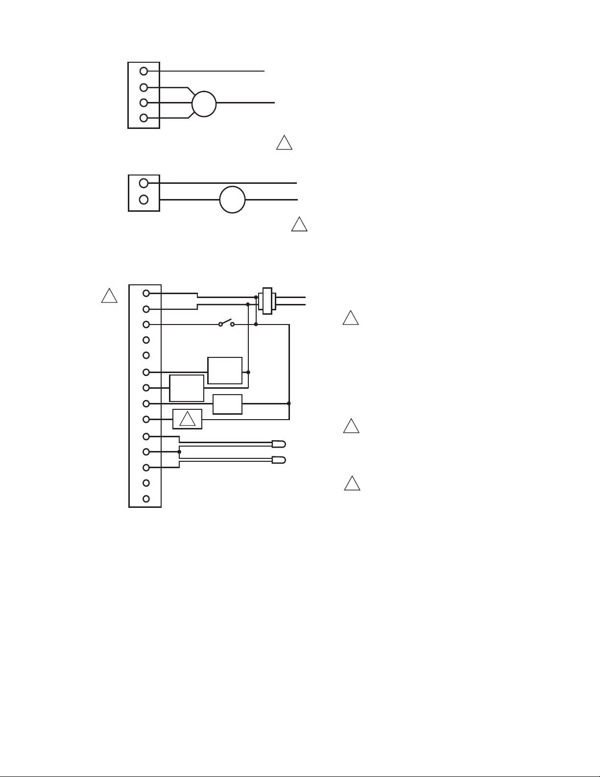
Figure-1 Typical Wiring.
1
1
2
2
2
For main and secondary
outputs, Terminal 6 is the
common and Terminal 5
is the power.
For setback, demand and
auxillary heat outputs
Terminal 5 is the common
and Terminal 6 is the power.
L1 (Hot)
LO
MED
HI
L2 OR NEUTRAL
24 - 277 VAC
VOLTAGE
CONNECTION
3 SPEED FAN CONTROL
TA168-002/TA168-003 CONTINUOUS FAN
FAN
1
2
3
4
24 - 277 VAC
VOLTAGE
CONNECTION
SINGLE SPEED FAN CONTROL
L1 (HOT)
L2 OR NEUTRAL
TA 168-007/TA168-008 CONTINUOUS FAN
FAN
1
4
For demand fan control,
power a 24V fan relay
using Terminal 12 as
the output. Output limited to 10 VA.
Can be used for second stage
24 Vac heat output or single
stage 24 Vac electric heat
output by setting dipswitch #2.
LOW VOLTAGE
CONNECTIONS
24 VAC
XFMR
SETBACK INPUT
SETBACK
SWITCH
SECONDARY
0-10 VDC
OR
4-20 mA
MAIN
0-10 VDC
OR
4-20 mA
OPTIONAL REMOTE PROBE
OPTIONAL CHANGEOVER SENSOR
5
6
7
8
9
10
11
12
13
15
16
17
18
19
DEMAND
OUTPUT
3
3
4 © Copyright 2010 Schneider Electric All Rights Reserved. F-27025-3
Page 5
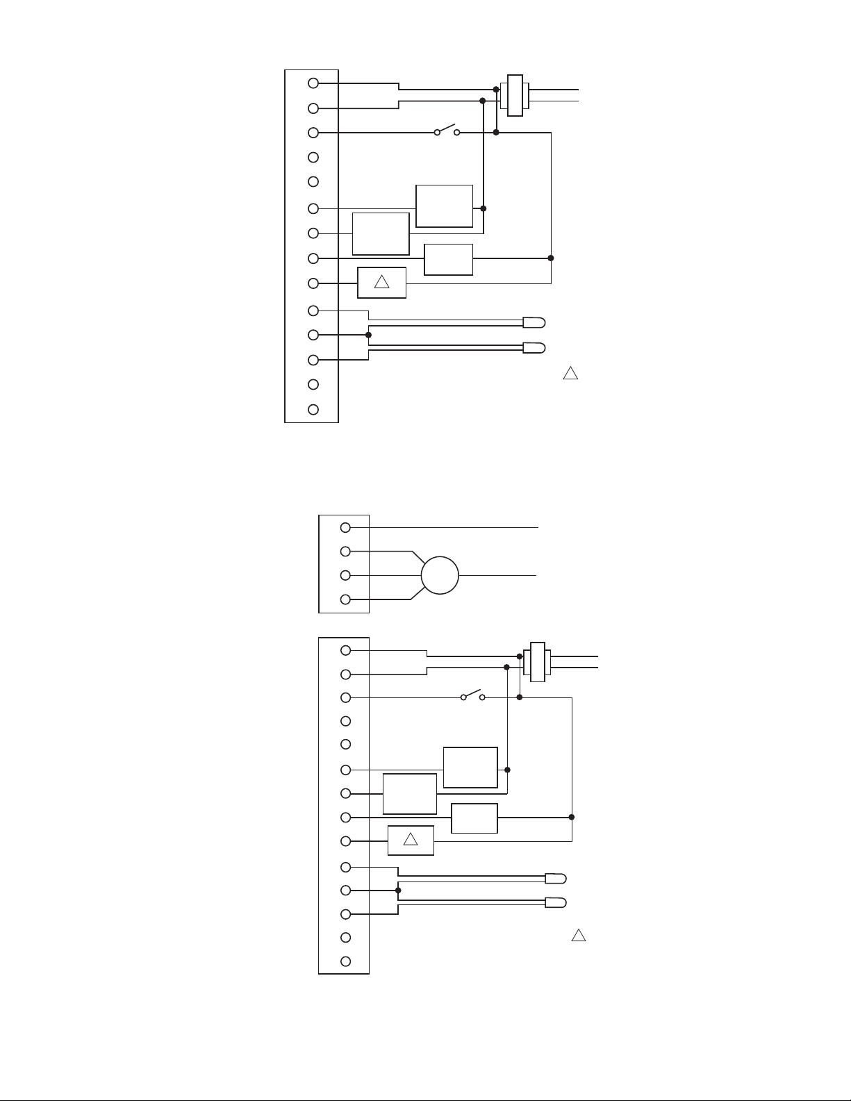
5
Figure-2 Typical Wiring for TA168-001 Dual Output Proportio nal Control.
L1 (HOT)
L2 OR NEUTRAL
LINE VOLTAGE
CONNECTIONS
FAN
1
2
3
4
LO
MED
HI
LOW VOLTAGE
CONNECTIONS
24 VAC
XFMR
SETBACK INPUT
SETBACK
SWITCH
SECONDARY
0-10 VDC
OR
4-20 mA
MAIN
0-10 VDC
OR
4-20 mA
OPTIONAL REMOTE PROBE
OPTIONALCHANGEOVER SENSOR
5
6
7
8
9
10
11
12
13
15
16
17
18
19
DEMAND
OUTPUT
Can be used for second stage
24 Vac heat output or single
stage 24 Vac electric heat
output by setting dipswitch #2.
1
1
Figure-3 Typical Wiring for TA168-002 and TA168-003 Dual Output Proportional Contro l with
Three-Speed Line Voltage Fan Control.
LOW VOLTAGE
CONNECTIONS
10
11
12
13
15
16
17
18
19
6
7
8
9
SETBACK INPUT
SETBACK
SWITCH
MAIN
0-10 VDC
SECONDARY
0-10 VDC
OR
4-20 mA
1
OPTIONAL REMOTE PROBE
OPTIONAL CHANGEOVER SENSOR
OR
4-20 mA
DEMAND
OUTPUT
24 VAC
XFMR
1
Can be used for second stage
24 Vac heat output or single
stage 24 Vac electric heat
output by setting dipswitch #2.
F-27025-3 © Copyright 2010 Schneider Electric All Rights Reserved. 5
Page 6

INSTALLATION
N O T E
N O T E
Inspection
Precautions
Inspect the package for damage. If damaged, notify the appropriate carrier immediately. If undamaged, open the package and inspect the device for obvious damage. Return damaged products.
Requirements
• Tools (not provided):
— Digital multimeter
— Screw driver
• Training: Installer must be a qualified, experienced technician
• Other accessories as appropriate
General
WARNING:
• Electrical shock hazard! Disconnect power before installation to prevent electrical shock
or equipment damage.
• Make all connections in accordance with the electrical wiring diagram and in accordance
with national and local electrical codes.
CAUTION:
• Avoid locations where excessive moisture, corrosive fumes, explosive vapors, or
vibration are present.
• Avoid electrical noise interference. Do not install near large conductors, electrical
machinery, or welding equipment.
Federal Communications Commission (FCC)
This equipment has been tested and found to comply with the limits for a Class B digital
device, pursuant to Part 15 of the FCC Rules. These limits are designed to provide reasonable protection against harmful interference in residential installations. This equipment generates, uses, and can radiate radio frequency energy and may cause harmful interference if
not installed and used in accordance with the instructions. Even when instructions are followed, there is no guarantee that interference will not occur in a particular installation. If this
equipment causes harmful interference to radio and television reception—which can be
determined by turning the equipment off and on—the user is encouraged to try to correct the
interference by one or more of the following measures:
• Reorient or relocate the receiving antenna.
• Increase the separation between the equipment and receiver.
• Connect the equipment to an outlet on a circuit different from that to which the receiver
is connected.
• Consult the dealer or an experienced radio/television technician for help.
Canadian Department of Communications (DOC)
This class B digital apparatus meets all requirements of the Canadian Interference-Causing
Equipment Regulations.
Cet appareil numerique de la classe B respecte toutes les exigences du Reglement sur le
material broilleur du Canada.
European Standard EN 55022
WARNING:
This is a class B (European Classification) product. In a domestic environment this product may cause radio interference in which case the user may be required to take adequate measures.
6 © Copyright 2010 Schneider Electric All Rights Reserved. F-27025-3
Page 7

Mounting
Figure-4 Mounting.
HOT
COMMON
24 V
24 V
Figure-5 Terminal Definitions.
Mount the T168 series to a suitable surface approximately five feet above the floor on an
inside wall. Standard holes are provided for mounting purposes. Do not mount on a surface
that exceeds 120°F (49°C). Refer to Figure-4. Do not mount near cold or warm air drafts
from doorways, windows or discharge air vents. Do not mount near lights, lamps or in direct
sunlight. do not mount behind doors or furniture. Do not mount on outside walls. Insulate
behind wall plate if necessary.
WIRING
F-27025-3 © Copyright 2010 Schneider Electric All Rights Reserved. 7
Page 8

.
Figure-6 Switches and Jumpers.
Cuttable Jumper/Dip
Switch Designation
On/Uncut Off/Cut
1 Not Used Not Used
2 Staged Heat Aux. On-Off Electric Heat
3 Fahrenheit Display Celsius Display
4 Output 0-10 Vdc
Output 4-20 mA (requires
the removal of JP4 and JP5)
5 Not Used Not Used
6
Un-Occupied Set Point 90°F
Cooling/50°F Heating
Un-Occupied Set Point 85°F
Cooling/60°F Heating
Pin Pair Jumper
Designation
Jumpered Open
JP1 Local Sensor Remote Sensor
JP2 2 Pipe 4 Pipe
JP3 Not Used Not Used
JP4 Main 0-10 Vdc Main 4-20 mA
JP5 Secondary 0-10 Vdc Secondary 4-20 mA
Switch
Handle
Position
OFF ON
1
23456 1
Shown
Closed
DIP SWITCH MODELS
1
23456 1
JP4
JP3
JP2
JP5
JP1
Older styles will have cuttable jumpers
uncut = On, cut = Off
Cuttable Jumpers
Not Used
Staged Heat
Fahrenheit Display
0-10 VDC C Output
Not Used
Cooling 90oF (32oC)
Heating 50
Setback
o
F (10oC)
CutUncut
Not Used
Electric Heat
Celsius Display
4-20mA Output
Not Used
Setback
Cooling 85oF (29oC)
o
Heating 60
F (16oC)
8 © Copyright 2010 Schneider Electric All Rights Reserved. F-27025-3
Page 9

INITIAL SETUP
N O T E
N O T E
Application Notes
SETTINGS
The T168 series thermostats are field configurable for a wide range of applications. Models
built after January 2000 have configuration dip switches in the upper right corner of the
circuit board. Models built before January 2000 were equipped with cuttable jumpers instead
of dip switches for field configuration.
In addition to dip switches there are pin jumpers which are pairs of small pins. The pin jumper
pairs are located on the right hand side of the T168 circuit board. The jumpered state means
that both pins are covered by the black plastic jumper cap. In the un-jumpered (open) state
the jumper cap can be stored by placing the cap over either pin of the pin pair. See
Figure-6 for further information on dip switches and jumpers.
A single set point serves as the set point for both heating and cooling.
Cooling/Heating Output Logic
The factory default for the main output is the cooling output and the secondary output is the heating output. Follow these steps to change the factory default.
Dual Output Models: Connect a jumper wire from terminal 16 to terminal 17 to make
the main output heating only, and the secondary output is disabled.
Single Output Models: Connect a jumper wire from terminal 16 to terminal 17 to make
the main output heating.
Seasonal Changeover Sensor
When installing the seasonal changeover sensor strap the sensor to the main coil input or a
pipe that will determine the fluid temperature of the coil. If a well is available, use thermal
grease for a faster temperature response. Insulate the entire sensor and pipe 2 inches
before and after the sensor for a total of approximately 6 inches. This insulation is used to
decrease the affect of ambient temperature on the sensor.
When no changeover sensor is installed on terminals 16 and 17 the main output defaults to cooling logic, which controls the output for cooling purposes.
When a changeover sensor is installed the main output is cycled from heating to cooling or
from cooling to heating. This depends upon the temperature measured by the changeover
sensor strapped to the supply pipe or mounted in the return air duct. Refer to “Seasonal
Changeover With The 65406 Sensor” in this document.
Remote Sensor (Room)
Install the sensor in a location that will only measure the temperature to be sensed without
any external heating or cooling sources influencing the sensor. Heating or cooling sources
to avoid include direct sunlight, mounting the sensor too low or too high on a wall, and areas
in ducts with dead air movement. Consider the room stratification and air movement on the
remote sensor location.
When using a remote sensor remove the jumper cap from pin pair JP1, located in the lower right corner of the circuit board. This will disable the onboard sensor. You can store the jumper cap on either pin of the JP1 jumper pair.
Failure to remove the jumper on JP1 will enable both the onboard and the remote sensors.
The T168 will not function properly.
Sensor Wire Length
In all applications, run the sensor wire away from any electronic noise generating device s,
such as motors, fluorescent lights, microwaves, or parallel to line voltage wiring. The
maximum length of non-shielded wire should not exceed 25 feet. Even if the sensor wire is
not near any noise generating devices, it still acts like an antenna and picks up background
noise that is read by the microprocessor.
F-27025-3 © Copyright 2010 Schneider Electric All Rights Reserved. 9
Page 10

In an electronic noisy environment or if the sensor wire must be located close to noisegenerating devices, always use shielded wire and connect the shielding to an earth ground.
If shielded wire is used and is properly grounded, the maximum length of the shielded sensor
wire should not exceed 100 feet.
—Improper wiring or mounting of sensors may cause the following:
—Sensing too high or too low of temperature.
—Delay in sensing the proper temperature.
—Not be able to sense the proper control media.
—Controllers have erratic control responses.
Signal Logic
The T168 is factory configured to provide a 0-10 Vdc signal. Dip switch 3 is On and pin pairs JP4 and JP5 have the jumper cap over both pins of the pair.
For 4-20 mA signal, move dip switch 4 to the Off position, then remove jumper caps on JP4 and JP5. Jumper caps can be stored on either pin of pin pairs JP4 and JP5.
Demand Heat Logic
If equipped with demand output the T168 will automatically provide a 24 V output (terminal
12) to power a fan relay any time there is a call or demand for heating or cooling. The
maximum switched load is 10 VA @ 24 V.
Auxiliary Heat Logic
If equipped with auxiliary heat output the T168 offers the user two options, a second stage
of on/off heat, or a single stage of electric heat. In both cases the auxiliary output (terminal
13) provides 24 V, and a rated load handling ability of 10 VA. Use a relay if the load will
exceed 10 VA.
Second Stage of Heat: T o enable second stage of heat logic dip switch 2 must be in the
On position. On a call for heat the first stage heat will provide the configured 0-10 Vdc
or 4-20 mA signal. At 2 degrees below the set point the T168 will provide a full
proportional 10 Vdc or 20 mA signal, completely opening the valve. If the temperature
continues to drop to 3 degrees below the set point, the T168 will bring on the 2nd stage
of heat by providing 24 V at terminal 13.
Electric Heat: To enable electric heat, dip switch 2 must be in the Off position. On a call
for heat the T168 will provide 24 V power at terminal 13. This output will cycle in on/off
mode subject to a 1 degree differential and maximum load of 10 VA at 24 V. There will
still be a 3 degree deadband between heating and cooling. There will be no 0-10 Vdc
or 4-20 mA heat output.
Setback Logic
When in setback mode both the cooling and heating outputs operate as on/off outputs.
When dip switch/jumper 6 is in the On state the T168 controls setback is set at 90°F cooling,
50°F heating. In the Off state the setback is set at 85°F cooling, 60°F heating.
Setback Mode: When a dry contact closure occurs to terminal 7 on the T168 the
setback mode is enabled. A building automation system or time clock can be used to
provide a dry contact, unpowered circuit to terminal 7.
Cooling Mode: At 3 degrees above set point, the cooling device will be fully opened and
will stay open until the temperature drops to the set back set point.
Heating Mode: At 3 degrees below the set point the heating device will be fully opened
until the temperature rises to the set back set point.
Setback Override: When in setback mode pressing any of three buttons, up arrow,
down arrow, or system mode, will force the T168 into a 1 hour override. In override the
thermostat will control the temperature at the non-setback mode set point.
Calibration
The T168 uses a 10K thermistor type sensor to measure temperature. As the air
temperature changes, the resistance of the thermistor changes. The change in the
resistance is fed into the processor and the processor adjusts the output to the control
device.
Up to 5 degrees of offset can be added or subtracted.
This is a software re-calibration of the room temperature displayed by the thermostat as well
10 © Copyright 2010 Schneider Electric All Rights Reserved. F-27025-3
Page 11

CHECKOUT
N O T E
temperature value (controlled variable) which is compared to the set point in order to
determine the thermostat output.
1. Supply 24 V a c to th e thermostat.
2. Press the mode button, scroll the thermostat until Off mode is displayed.
3. Push the up and down arrows at the same time, hold them in the depressed position.
4. In 1 second the display will show an offset value if an offset was previously entered. If there was no offset the display will read “0.0”.
5. An offset can be set up to either positive or negative 5 degrees. a. To create a positive offset, release the down arrow while keeping the up arrow
depressed, until the desired offset is displayed up to 5 degrees.
Example: If the temperature sensor reads 70°F with a 5 degree positive offset the thermostat will read 75°F.
b. To create a negative offset, release the up arrow while keepi ng the down arrow
depressed, until the desired offset is displayed up to 5 degrees.
Example: If the temperature sensor reads 70°F with a 5 degree negative offset the
thermostat will read 65°F.
6. When the correct offset value is displayed release both the up and down arrows.
7. After a two second delay the display will indicate the room temperature and the plus or minus offset entered.
Verify the dip switch and jumper pin settings.
Verify that the 24 Vac is permanently available across terminal 5, hot, and terminal 6,
Common.
CAUTION:
Make certain that all switched loads are within the 10 Va switched power maximum.
Verify that the action (direct or reverse) and the signal logic (0-10 Vdc or 4-20 mA) of the
controlled device (valve or actuator) are consistent with the T168 signal logic. In Cooling
mode, on a rise in ambient temperature, the output is ramped up. In Heating mode, on a rise
in temperature the output is ramped down.
To verify the heating or cooling 0 - 10 Vdc outputs: Connect a voltmeter in parallel across terminal 6, common, and terminal 10 for cool ing logic or terminal 11 for heating logic.
To verify the heating or cooling 4 - 20 mA outputs: Connect an amp meter in series with the controller output and terminal 10 for cooling or terminal 11 for heating.
To verify heating or cooling outputs when in night setback: Check for 24 Vac in parallel across terminal 6, common, and terminal 10 for cooling or terminal 11 for heating.
• In setback mode the logic is on/off not proportional.
• The common terminal is not the same for all outputs.
To verify contact closure in setback mode: Check for 24 Vac in parallel across terminals 5, common, and terminal 7, hot.
T o verify the 24 Vac demand output: Check for 24 Vac in parallel across demand terminal 12 and terminal 5, common.
To verify the auxiliary heat/2nd stage heat output: Check for 24 Vac in parallel across auxiliary terminal 13 and terminal 5, common.
THEORY OF OPERATION
Control Algorithm
The PI control algorithm has a 2F degree proportional band. The proportional band is the
amount of change required by the ambient temperature for the output to go from 0 to 100%.
For example, in the heat mode, with a 70°F set point and an ambient temperature of 70°F
the output is 0%; at 69°F the output is 50%; and at 68°F the output is 100%. The intergral
gain implies that the longer the error between the ambient and the set point temperatures
F-27025-3 © Copyright 2010 Schneider Electric All Rights Reserved. 11
Page 12

exists, the more the output will change to eliminate the error. The intergral portion of the
100%
0%
-3 -2 -1 Set Point +1 +2
+3
50%
% Of Output
0-10 Vdc
or
4 - 20 mA
100%
0%
-3 -2 -1 Set Point +1 +2
+3
50%
% Of Output
0-10 Vdc
or
4 - 20 mA
algorithm eliminates the temperature offset from the set poi n t.
Heat mode
When the ambient temperature is below the set point the output is somewhere between 0 and 100% the T168 is in “Heat” mode.
Cool mode
When the ambient temperature is above the set point the output is somewhere between 0 and 100% the T168 is in “Cool” mode.
Seasonal Changeover With the 65406 Sensor
12 © Copyright 2010 Schneider Electric All Rights Reserved. F-27025-3
Auto mode
Upon initial startup the controller is in the auto mode. The controller determines
automatically if it should be in the “Auto-Heat” or “Auto-Cool” mode, based on the set point
and the ambient temperature. When the ambient temperature is below the set point, the unit
is in the “Auto-Heat” mode. When the ambient temperature reaches the set point or above
by up to 3°, the unit is in the “Auto” mode. Once the ambient temperature reaches 3° past
the satisfied set point the unit changes into the “Auto-Cool” mode. Since the ambient
temperature is 3° past the set point, the output goes to 100%. The unit remains in the “AutoCool” mode until the ambient temperature reaches the set point. If the ambient temperature
drops below the set point the modes changes into the “Auto” mode. When the ambient
temperature reaches 3° below the set point the mode changes to the “Auto-Heat” mode.
100%
% Of Output
0-10 Vdc
or
4 - 20 mA
50%
0%
Note: The following represents:
The seasonal changeover logic will compare the sensed temperature at the pipe sensor thermistor with the actual ambient, room temperature as measured by the onboard thermistor in the thermostat.
During initial startup the thermostat determines the resistance value wired across terminals 16 and 17.
-3 -2 -1 Set Point
Auto
+1 +2 +3
Auto Heat Auto Cool
Page 13

If the resistance value is:
Below 350 ohms: There is a jumper wire across terminals 16 and 17 which locks the
thermostat into a heating only logic. Both the single or dual output thermostats will be
configured as single output heating only thermostats. The heating output will be the
main and only output. The processor will not be polled and will not check the status of
the changeover terminals.
Over 350,000 ohms: With no jumper or a 65406 thermistor installed across terminals
16 and 17 the heating and/or cooling outputs will work normally. The main output is for
cooling and the secondary output is for heating.The processor will not be polled and will
not check the status of the changeover terminals.
Between 350 ohms and 350,000 ohms: There is a 65406 thermistor installed across
terminals 16 and 17 of the thermostat. The processor will poll the resistance once every
second and will then authorize the main output to control in either heating or cooling
depending on the continuously changing value of the resistance.
2 Pipe Seasonal Changeover Sensor Operation
The TA168-004, when in summer operation, with the pipe sensor feeling cold water (15°F
below thermostat ambient), the thermostat will be in Cool mode and operate the control
valve for cooling. When the pipe sensor feels hot water (15°F above thermostat ambient),
the thermostat will changeover to winter operation and will be in Heat mode to operate the
valve for heating. Should the thermostat once again feel cold water it will change back to
summer operation and be in the Cool mode.
If the controller senses that the seasonal changeover temperature is within ±15°F of the
ambient temperature, the mode is ambiguous. During this ambig uous state, if there is a
demand for heating or cooling, the controller will carry out the following steps to determine
if cooling or heating is available.
1. The word “Auto” is displayed indicating the ambiguous state:
• “Auto” only indicates the ambiguous state with no demand for either heating or
cooling.
• “Auto Heat” or “Auto Cool” indicates the ambiguous state with a demand for heating
or cooling based on the differential between the ambient temperature and the set
point.
2. The controller operation is limited to two position control, 100% open or 100% closed.
3. With a demand for heating or cooling, a three minute timer is started for a purge cycle. During the purge cycle the control valve is fully open.
4. After purging for three minutes the controller again checks the seasonal changeover temperature for the ambiguous state. If the mode is no longer ambiguous the controller resumes normal operation.
If the mode is still ambiguous the controller does the following:
1. Continues to hold the main valve open.
2. Checks if the seasonal changeover temperature is less than 60°F or greater than 80°F.
If the temperature is less than 60°F (cooling mode) or greater than 80°F (heating mode)
the controller is declared to no longer be in an ambiguous state and starts to control
appropriately.
3. If the temperature is between 60°F and 80°F the controller is still viewed as being in an
ambiguous state and the purge continues with testing every three minutes until a nonambiguous state occurs based on the ±15°F criteria or the 6°F/80°F criteria.
4. Once a non-ambiguous state is detected the controller waits for a one hour before
checking and allowing another purge cycle to occur. During this hour changes from
heating to cooling and back are possible by pipe sensor changes of more than ±15°F
from the ambient.
On startup, if the mode is ambiguous the controller will go directly to the purge cycle rather than the normal start-up logic.
F-27025-3 © Copyright 2010 Schneider Electric All Rights Reserved. 13
Page 14

MAINTENANCE
Figure-7 T168 Series Dimensions.
FIELD REPAIR
DIMENSIONAL DATA
The T168 series requires no maintenance. Replace defective modules.
Regular maintenance of the total system is recomended to assure sustained, optimum
performance.
None. Replace any damaged or failed components with functional replacements.
MODE
2-3/4
(70)
OFF HI MED LO
FAN
1-1/8
(28)
(25)
1
MOUNTING SLOTS (2)
1/8 X 3/8 (4 X 10)
1/2
(13)
OPENING FOR WIRING
3/8
(8)
2-1/8
(53)
3-1/4
(84)
4-1/2
(114)
14 © Copyright 2010 Schneider Electric All Rights Reserved. F-27025-3
Page 15

F-27025-3 © Copyright 2010 Schneider Electric All Rights Reserved. 15
Page 16

On October 1st, 2009, TAC became the Buildings business of its parent company Schneider Electric. This document reflects the vi sual ide nti ty of Schn eider Elec tric,
ho wever t her e remains ref erences to TAC as a corporate br and in the body copy. As each doc um ent is upda ted, the body copy will be changed to r e flect appropriat e
corporate brand changes.
Copyright 2010, Schneider Electric
All brand names, trademarks and registered
trademarks are the property of their respective
owners. Information contained within this
document is subject to change without notice.
F-27025-3
 Loading...