

Page 1

Powerlogic
Easergy P5
Catalog 2020
Network protection relays
www.se.com/easergy
Page 2

Note: Electrical power systems are dangerous, protection relays are defined and governed
by international standards such as IEC 60255 “Measuring relays and protective equipment”
and IEEE C37.97 “Protective relay applications to power systems buses”. Never attempt to
install or operate protection relays or associated equipment without the necessary
qualifications, training and tools. Exposure to electrical arc-flash incidents can be life
threatening, no situation can ever be deemed fully safe. Standards such as NFPA 70E define
important risk categorization and such standards identify both distance from, and energy of
the arc incident to be important factors. In order to reduce the risk category and improve
safety during arc-flash incidents, functionality is available in Easergy P5 protection relays to:
i) to operate electrical panel from a safer distance via wireless communication, and ii) arcflash protection functionality to detect and limit the arc energy by tripping the connected
circuit breaker faster than in a conventional protection scheme.
Page 3

PM107471
General Contents
Easergy P5
Range description
Product description
Digital experience
Additional modules and accessories
5
48
76
82
Services
Ordering
96
102
schneider-electric.com | 3Easergy P5 Catalog
Page 4

Easergy P5
Range description
schneider-electric.com4 | Easergy P5 Catalog
Page 5

Easergy P5
Range description
Overview
Selection guide
10
11
Selection guide by functionality 12
Selection guide by application 14
Feeder / Incomer application 14
Motor application 15
Transformer application 16
Arc-flash application 18
Capacitor application 19
Functions and description
Communication
Examples of architectures 42
Redundancy protocols 43
Time synchronization 44
20
42
Data exchanged 45
Cybersecurity
Cybersecurity - Basic level 46
Cybersecurity - Advanced level 47
46
schneider-electric.com | 5Easergy P5 Catalog
Page 6
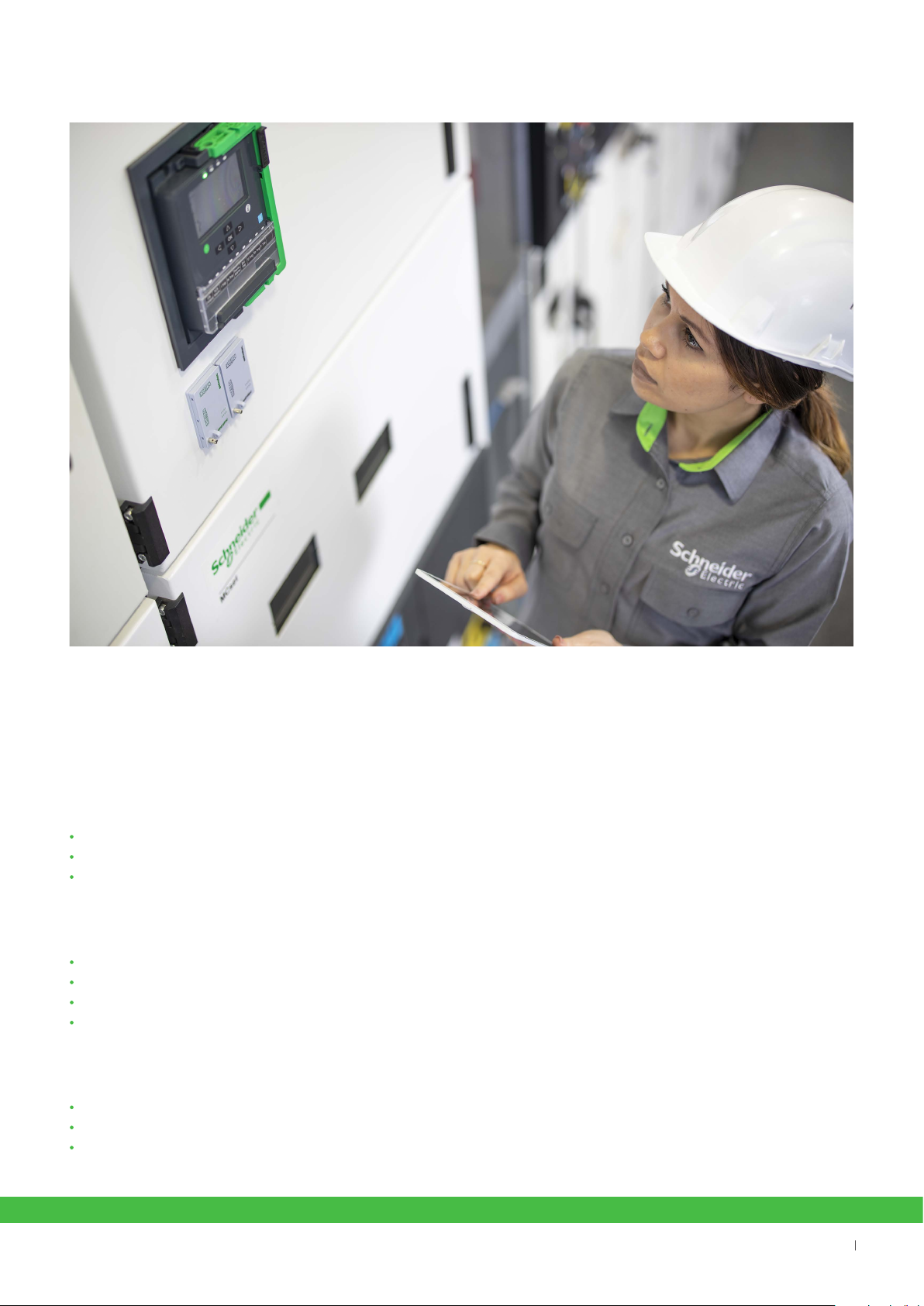
The Easergy P5 at a glance
The Easergy P5 is a protection relay for demanding medium-voltage applications. It offers users industry-leading
dedicated protection relay functionality to reduce risks, improve reliability, all with advanced connectivity. Additionally, it
can be used with a range of digital tools that make everyday operations simpler for users. The Easergy P5 is part of the
PowerLogic range of power monitoring and control solutions and has been built on more than 100 years of experience
in protection relays, including Sepam, MiCOM, and Vamp ranges, renowned for their reliability and performance.
Industry-leading protection functions
Built-in arc-flash protection function (optional)
Nearby control with a mobile application
Latest cybersecurity built in, with IEC 62443 standard compliance and Achilles certification
Best-in-class reliability
Withdrawable design for quicker maintenance
Backup memory function enabling industry-leading 10 minute recovery time!
Condition monitoring for reduced risk of power outages and maximized equipment life
Extended equipment lifetime when used with EcoStruxure Asset Advisor
Maximized everyday simplicity
Easier operation with digital tools including the EcoStruxure Power Device app
Powerful communication with plug and play ports and seven protocols supported
Scalable hardware making it easy to upgrade as your applications evolve
schneider-electric.com6 | Easergy P5 Catalog
6
Page 7

Enjoy a package of sought-after
features in one device
The Easergy P5 presents a major step forward for protection relays,
bringing a number of best-in-class features together in one device.
Built-in arc-flash protection functions
Arc-flashes will always exist when switching or during unexpected conditions.
The protection function detects if an arc-flash exists, and take action within
milliseconds to isolate the connected circuit breaker, meaning that
arc-flash energy should not grow and cause unexpected outages or risks.
Advanced cybersecurity
IEC 62443 compliant, the Easergy P5 has been designed with an optional
cybersecurity package. This means reduced exposure to cyber threats
and improved operational security. By default, the Easergy P5 includes
important features such as password management, port hardening, and
secured communication compliant to the latest international standards.
Intuitive withdrawable design
With a handle built in as part of the design, the P5 can be quickly
disconnected or exchanged to speed up maintenance. Wiring, data,
communication, and settings (including backup) can be stored with the
panel and will be there when the relay is reconnected.
Improved recovery time
When maintenance or testing is required, Easergy P5 helps dramatically decrease your outage recovery time. The backup
memory can automatically restore settings, you can continue your operations in as little as 10 minutes.*
*Result of mean time to repair (MTTR) calculation conducted by Schneider Electric
Greater connectivity
The protection relay features seven communication protocols. This includes compliance with IEC 61850 Edition 1 and Edition
2, Modbus (serial/TCP), IEC 60870-5-103, IEC 60870-5-101, Ethernet/IP, and DNP3 (serial/TCP). Easergy P5 can support up
to 3 Ethernet protocols simultaneously, including offering dual redundancy with PRP/HSR and RSTP protocols. Moreover, all
communication modules can be added at any time, including on-site, during the product life cycle to allow you to upgrade
your device in line with future network evolutions.
schneider-electric.com | 7Easergy P5 Catalog
7
Page 8

Make everyday operations
easier with digital tools
The Easergy P5’s industry leading protection features are complemented by a comprehensive set of tools
available on mobile devices such as smartphones or tablets, and desktop computers. This means you get
simpler installation, configuration, and maintenance, enabling you to save time and money. Nearby control
and monitoring allows users to fully operate the device via wireless communication, from a safer distance.
Digital tools for the Easergy P5 include:
EcoStruxure Power Build – Medium Voltage online ordering tool enables quicker and easier ordering
eSetup Easergy Pro software with virtual injection testing
Embedded web server, allowing easy and fast setting changes from a web browser
EcoStruxure™ Power Device app for simpler and safer operation and maintenance
mySchneider app, a simple way to access support and product data by flashing the QR code
on the device
As an EcoStruxure-ready solution, the Easergy P5’s digital benefits can be taken even further with best-in-class
monitoring of substation equipment health. For example, when paired with EcoStruxure Asset Advisor, users
get data for predictive maintenance, which helps them reduce OpEx, speed up processes,
and boost efficiency.
schneider-electric.com8 | Easergy P5 Catalog
Page 9

Take Easergy P5 further with
Connected Products
Edge Control
Apps, Analytics & Services
End to End
Cybersecurity
Cloud and/or
On
Premise
Infrastructure
Building
Data Center
Industry
EcoStruxure
TM
EcoStruxure, Schneider Electric’s IoT-enabled, open and interoperable
architecture and platform, brings together Connected Products, Edge
Control, and Apps, Analytics & Services. EcoStruxure connected products
deliver enhanced value around safety, reliability, efficiency, sustainability,
and connectivity.
EcoStruxure ready
450 000
EcoStruxure systems deployed since
2007 with the support of our 9,000
system integrators
Efficient asset management
Boost your efficiency and
reduce downtime using
predictive maintenance tools
EcoStruxure™ Architecture
24/7 connectivity
Make better informed decisions
with real-time data that’s
available everywhere, anytime
Enhanced safety
Advanced features designed-in
based on well-known designs,
experience and technology
EcoStruxure
Power
schneider-electric.com | 9Easergy P5 Catalog
EcoStruxure
Building
EcoStruxure
IT
EcoStruxure
Machine
EcoStruxure
Plant
EcoStruxure
Grid
9
Page 10

Easergy P5
Overview
Range description
Easergy P5 protection relay is based on proven technology concepts and developed in close cooperation with customers,
so it’s built to meet your toughest demands:
• Modular design that allows user-defined conventional protection and arc-flash protection solutions.
• Compatible with conventional CTs/VTs or low power instrument transformers LPCT/LPVT compliant to IEC 61869-10 and IEC 61869-11
standards.
• Embeds latest cybersecurity functionality to help prevent intentional mis-use and cyber-threats.
• Fast replacement with enhanced safety thanks to withdrawability and back-up memory that automatically restore parameters without using
any configuration tools.
Easergy products are designed to be user friendly, a feature that is proven in our customer reports day after day. You’ll
benet from features that include:
• A complete set of protection functions, related to the application.
• Arc-flash detection in Easergy P5x30 models.
• Dedicated circuit breaker control with single-line diagram, push buttons, programmable function keys, LEDs, and customizable alarms.
• Multilingual HMI for customized messaging.
• Settings tool relay management software for setting parameters, configuring, and network fault simulation.
• Both serial and Ethernet communication, including redundancy.
• IEC 61850 standard Edition1 & Edition 2.
Easergy P5 is available in two sizes
to best t your needs:
PM107437
Easergy P5x20 Easergy P5x30
PM107451
Range overview
DM107110
P5G30
Generator
P5U20
Universal
P5T32
Transformer
dierential
T U L L
Easergy P5 digital protection relays are designed for power distribution
networks in:
• Utilities - Energy distribution
• Critical buildings and Industry:
– Data Center
– Healthcare
– Transportation
– Industrial buildings
P5L30 P5F30
FeederDirectional & Line dierential
P5U20
Universal
• Large industrial processes:
– Oil and Gas
– Mining
– Mineral and Metals
– Water
P5V20
Voltage/Frequency
P5M30
Motor
V
F
U
G
G
T U L L
U
G
U
U
U
M
schneider-electric.com10 | Easergy P5 Catalog
M
M
Page 11
Easergy P5
Range description
Easergy P5 contains two main devices, each
with specific functions to address your needs
in a one-box design, regardless of application.
Selection guide
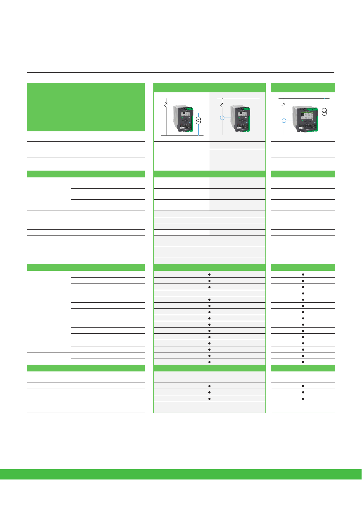
Easergy P5x20 Easergy P5x30
DM107111
DM107112
DM107113
Voltage
Feeder
Transformer
Motor
P5V20 -
P5U20
-
with directional in
LPCT/LPVT version
P5F30 with directional
P5M30 with directional
-
-
Characteristics
Phase current -
Measuring inputs
Arc-flash sensor inputs - 0 to 6 point sensors
Digital
Temperature sensor input - 0 to 16 (external modules) 0 to 16 (external modules)
Front ports
Power supply 24-250 VDC ; 100-230 VAC
Ambient temperature, in service -40 to 70°C (-40 to 158°F) -40 to 70°C (-40 to 158°F)
Residual current -
Voltage VT (x4) LPVT (x4)
Inputs 4 to 16 4 to 40
Outputs 3 to 8 + Watchdog (WD) 3 to 18 + Watchdog (WD)
1 USB for configuration
1 USB for USB key
1/5A CT (x3)
or LPCT (x3)
1/5A CT & 1A CT
or CSH core balance CT
(1)
(1)
1/5A CT (x3)
or LPCT (x3)
1/5A CT & 1A CT
or CSH core balance CT
VT (x4)
or LPVT (x4)
1 USB for configuration
1 USB for USB key
24 - 48 VDC or
48-250 VDC ; 100-230 VAC
Communication
(2)
+ Backup memory
(3)
(4)
Hardware modules
Protocols
Redundancy
protocols
Time synchronization
Extension
Serial
Ethernet
2nd Ethernet IEC 61850 Ed.1 & Ed.2
IEC 60870-5-103 & 101
DNP3 Ethernet
DNP3 serial
Modbus Ethernet
Modbus serial
EtherNet IP
RSTP
PRP / HSR
Pulse, IRIG-B
SNTP, PTP IEEE 1588 v2
Others
Control
Logic (Matrix + Logic Equations)
Cybersecurity
Draw-out device (withdrawability)
Hardware dimensions (H/W/D)
6 controlled + 2 monitored objects
Mimic
102 / 176 / 219 mm
4.01 / 6.93 / 8.62 in
6 controlled + 2 monitored
objects Mimic
152 / 176 / 219 mm
6.0 / 6.93 / 8.62 in
(1) In case P5U20 is choosen for cooperation with low power sensors, it contains LPCT (x3) and LPVT (x4) channels
(2) for connection of RTD module and IRIG-B module
(3) IRIG-B module is a separate accessory
(4) PTP IEEE 1588 v2 is availaible with HSR/PRP communication board
schneider-electric.com | 11Easergy P5 Catalog
Page 12

Easergy P5
Selection guide by
Range description
functionality
Protection Functions
Current protection
Phase overcurrent 50/51 OCPTOC - 3 3 3 3
Earth/ground fault overcurrent
Directional phase overcurrent 67 DOCPTOC - - 4 4 4
Directional earth/ground fault
overcurrent
Transient intermittent/ground fault 67NI IOIOPTEF - - - 1 -
Neutral admittance 21YN EFPADM - - - 2 2
Negative sequence overcurrent 46 (I2/I1) NEGPTOC - 1 1 1 1
Current unbalance, Broken conductor 46BC (I2) UIBCPTOC - 1 1 1 -
Breaker failure 50BF CBFPPIOC 1 1 1 1 1
Phase undercurrent 37 UCPTUC - 1 1 - 1
Switch on to fault (SOTF) 50HS - 1 1 1 1
Cold load pickup (CLP or CLPU) - 1 1 1 1
Voltage protection
Undervoltage 27 UVPTUV 3 - 3 3 3
Overvoltage 59 OVPTOV 3 - 3 3 3
Earth/ground fault overvoltage 59N UOPTOV 3 - 3 3 3
Negative sequence overvoltage 47 NEGPTOV 2 - 2 2 2
Frequency protection
Over and/or underfrequency 81 OFUFPTOF 2 - 2 2 2
Underfrequency 81U UFPTUF 2 - 2 2 2
Rate of change of frequency 81R DFDTPFRC 2 - 2 2 -
Thermal protection
Thermal overload 49 THFPTTR - 1 1 1 1
Temperature monitoring 38 RTDGAPC - 16 16 16 16
Power protection
Wattmetric earth/ground fault 32N EFPDOP - - - 2 2
Directional active underpower 32/37N REVPPDOP - - 2 2 2
Rotating machine protection
Frequent start inhibition 66 FSTPMRI - 1 1 - 1
Motor start-up supervision, locked rotor 48/51LR STALPMSS - 1 1 - 1
Positive sequence undervoltage 27P UVPSPTUV 2 - - - 2
Underspeed
Overspeed
Anti-backspin
Line protection
Fault locator 21FL FLRFLO/SCRFLO - - - 1 -
Auto-Recloser 79 ARRREC - 1 1 1 -
Transformer protection
Magnetizing inrush detection 68H2 HAR2PTOC - 1 1 1 1
Fifth harmonic detection 68H5 HAR5PTOC - 1 1 1 1
Capacitor protection
Capacitor bank unbalance 51C - 2 - 2 -
Capacitor overvoltage 59C - 1 - 1 -
Other protection
Arc-flash detection 50ARC ARCMPIOC - - - 8 8
Programmable stages 99 PSGAPC 8 8 8 8 8
Programmable curves 3 3 3 3 3
Control, monitoring, supervision
Synchronization check 25 RSYN 1 - - 1 -
Lockout relay 86 1 1 1 1 1
CT supervision 60 CTSGGIO - 1 1 1 1
VT supervision 60 VTSGGIO 1 - 1 1 1
Setting groups 4 4 4 4 4
(1) Number of stages depends on the number of residual current inputs. (2) Function available if 12 DI / 4 DO board is present
(2)
(2)
(2)
(1)
ANSI
code
50N/51N EFPTOC - 5 / 8 3 5 / 8 5 / 8
67N DEFPTOC - - 3 3 3
14 M OTPZSU - 2 2 - 2
12 M OTPOVS - 2 2 - 2
ABS MABSPMSS - 1 1 - 1
IEC 61850
Logical Node
P5V20 P5U20
P5U20
LPCT/LPVT
P5F30 P5M30
schneider-electric.com12 | Easergy P5 Catalog
Page 13

Easergy P5
Selection guide by
Range description
functionality
Control functions P5V20 P5U20
Control with Mobile application
Switchgear control and monitoring 6 6 6 6 6
Switchgear monitoring only 2 2 2 2 2
Programmable switchgear interlocking
Local control on single-line diagram
Local switchgear control with OPEN/CLOSE keys
Local/remote function
Function keys 1 1 1 7 7
Custom logic (equations)
Measurement functions P5V20 P5U20
RMS current values
RMS voltage values
RMS active, reactive and apparent power
Frequency
Fundamental frequency current values
Fundamental frequency voltage values
Fundamental frequency active, reactive and apparent power values
Power factor
Motor speed detection
Energy values: active and reactive
Demand values: phase currents
Demand values: active, reactive, apparent power and power factor
Maximum demand values: phase currents
Minimum and maximum demand values: RMS phase currents
Minimum and maximum demand values:
active, reactive, apparent power and power factor
Maximum demand values over the last 31 days and 12 months:
active, reactive, apparent power
Minimum demand values over the last 31 days and 12 months:
active, reactive power
Maximum and minimum values: currents
Maximum and minimum values: voltages
Maximum and minimum: frequency
Maximum and minimum:
active, reactive, apparent power and power factor
Harmonic values of phase current and THD
Harmonic values of voltage and THD
Voltage sags and swells
(1)
P5U20
LPCT/LPVT
P5U20
LPCT/LPVT
P5F30 P5M30
P5F30 P5M30
Logs and records P5V20 P5U20
Sequence of event record
Disturbance record
Tripping context record
Relay maintenance data log
Security data log
Monitoring functions ANSI code P5V20 P5U20
Trip circuit supervision 74 1 1 1 1 1
Circuit breaker monitoring 1 1 1 1 1
Relay monitoring
(1) Function available if 12DI / 4DO board is present
schneider-electric.com | 13Easergy P5 Catalog
P5U20
LPCT/LPVT
P5U20
LPCT/LPVT
P5F30 P5M30
P5F30 P5M30
Page 14
Easergy P5
Selection guide by application
Range description
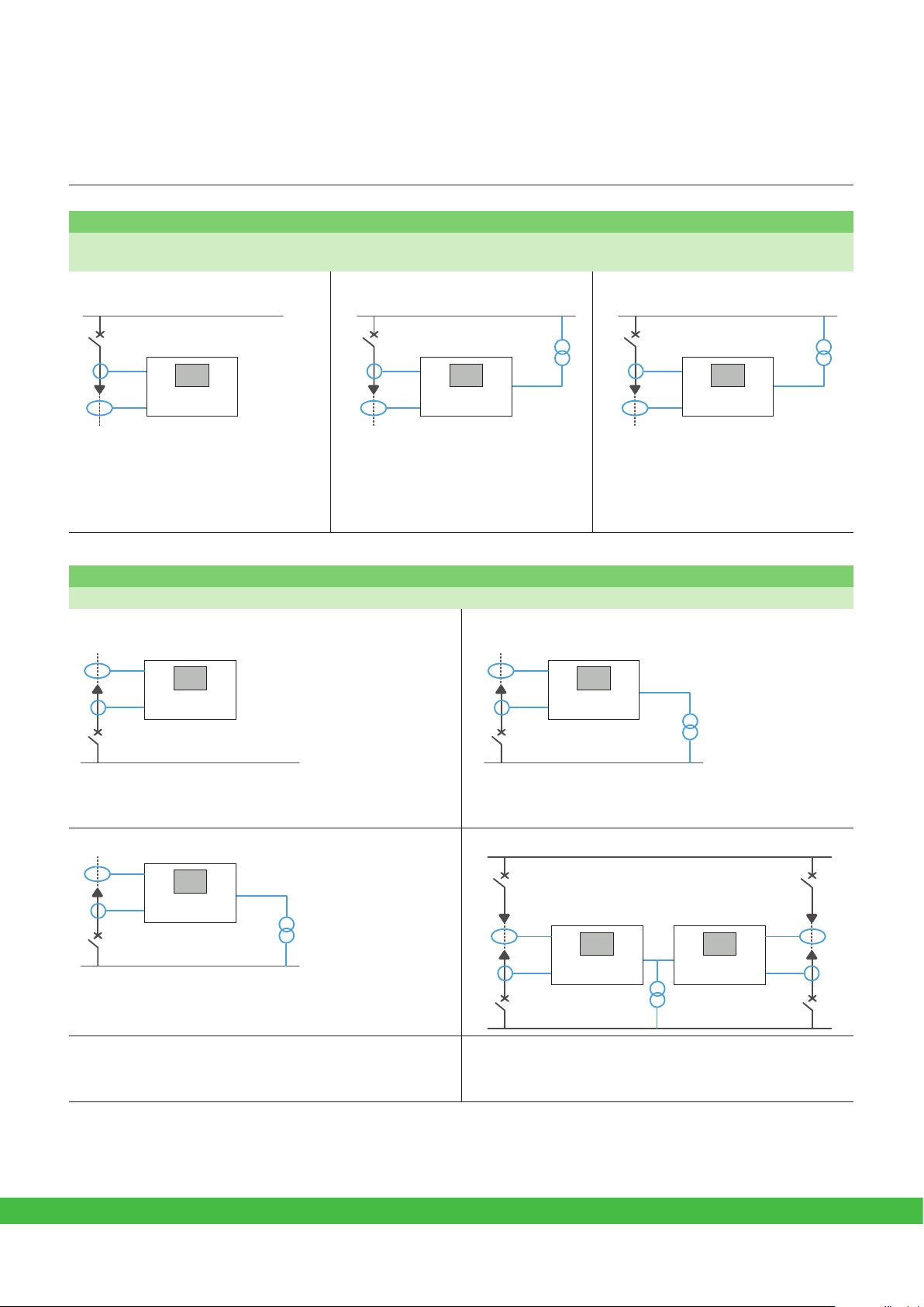
Feeder / Incomer application
Outgoing protection
• Feeder overcurrent protection
• Feeder overload protection
Feeder protection Overhead line protection Protection of feeders with metering
DM107117
P5U20 P5F30
• Feeder earth/ground fault overcurrent • Directional phase and earth/ground fault
DM107118
overcurrent
• Recloser
P5F30
DM107119
P5F30
• Power and energy measurement
• Min and max demand values over the last
31 days and 12 months
• Fault locator
Incomer protection
• Busbar overcurrent protection
Incomer protection without voltage monitoring Incomer protection with voltage and frequency monitoring
DM107120
P5U20 P5F30
DM107121
P5F30
• Earth/ground fault overcurrent • Under/over voltage
• Frequency, rate of change of frequency
Incomer protection with power quality monitoring Parallel incomer protection
DM107122
P5F30
DM107123
P5F30 P5F30
• Voltage and frequency min and max values
• Voltage harmonic values and THD
• Voltage sags and swells
• Directional phase overcurrent
• Directional earth/ground fault overcurrent
schneider-electric.com14 | Easergy P5 Catalog
Page 15
Easergy P5
Selection guide by application
Range description
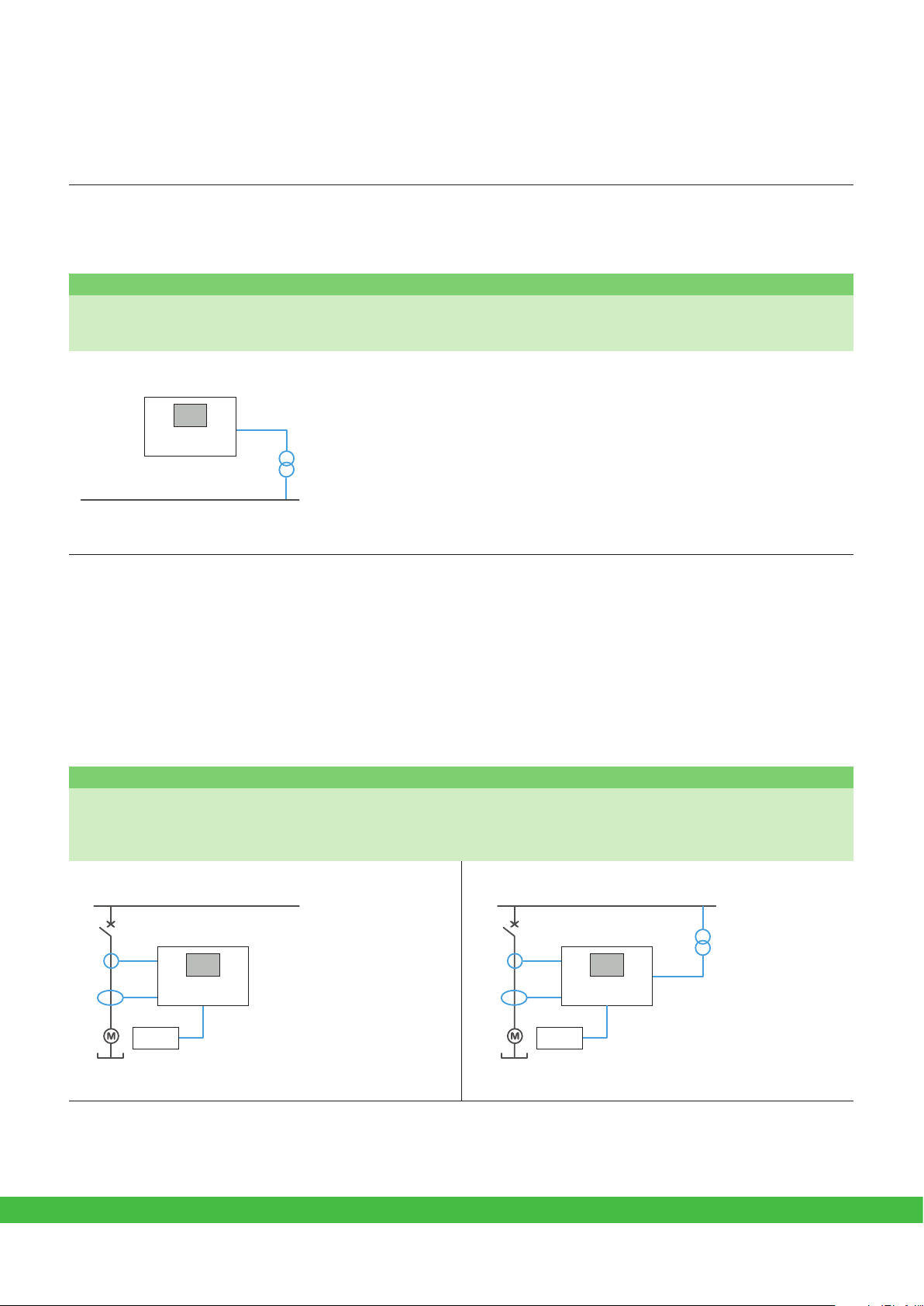
Feeder / Incomer and Motor applications
Feeder / Incomer application
Voltage monitoring
• Under/over voltage protection
• Earth/ground fault overvoltage
• Under/over frequency protection
DM107124
P5V20
• Load-shedding-specific function: rate of change of frequency
Motor application
Motor protection
• Motor overcurrent and earth/ground fault overcurrent
• Thermal overload
• Motor start-up supervision
• Motor restart inhibition
Motor protection without voltage monitoring Motor protection with voltage monitoring
DM107125
P5U20 P5M30
RTD module
MET148-2
• Temperature measurement (stator, bearings) • Undervoltage protection
DM107126
RTD module
MET148-2
P5M30
schneider-electric.com | 15Easergy P5 Catalog
Page 16

Easergy P5
Selection guide by application
Range description
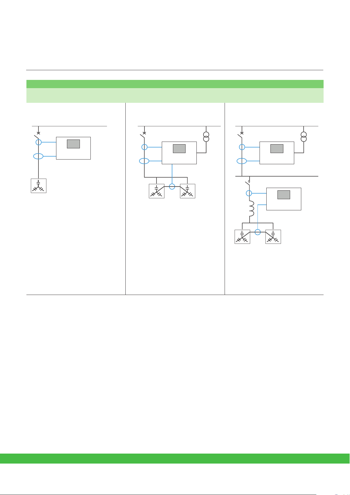
Transformer application
Transformer feeder protection
• Transformer overcurrent and earth/ground fault overcurrent protection
• Thermal overload protection
• External trip from thermostat/Buchholz
Transformer feeder protection without voltage monitoring Transformer feeder protection with voltage monitoring
DM107127
P5U20 P5F30
26
63
RTD module
MET148-2
DM107128
49T
P5F30
26
63
• Temperature measurement (ambient, oil) • Over and undervoltage protection
Transformer feeder protection with additional current measurement
DM107129
49T
P5F30
26
63
DM107130
49T
P5F30
26
63
• Tank earth/ground leakage protection • Earth/ground fault overcurrent on the secondary side
schneider-electric.com16 | Easergy P5 Catalog
Page 17

Easergy P5
Selection guide by application
Range description
Transformer incomer protection
• Busbar overcurrent protection
• Inter-trip from primary circuit breaker protection
Transformer incomer protection without voltage monitoring Transformer feeder protection with
DM107131
P5U20 P5F30
• Transformer earth/ground fault overcurrent • Earth/ground overcurrent for transformer
Transformer application
DM107132
P5U20 P5F30
and back-up protection
voltage monitoring
DM107133
P5U30
P5F30
• Over and undervoltage protection
• Power and energy measurement
• Min and max demand values over the last
31 days and 12 months
Parallel transformer incomer protection
DM107134
P5F30 P5F30
• Directional phase overcurrent
schneider-electric.com | 17Easergy P5 Catalog
Page 18
Easergy P5
Selection guide by application
Range description
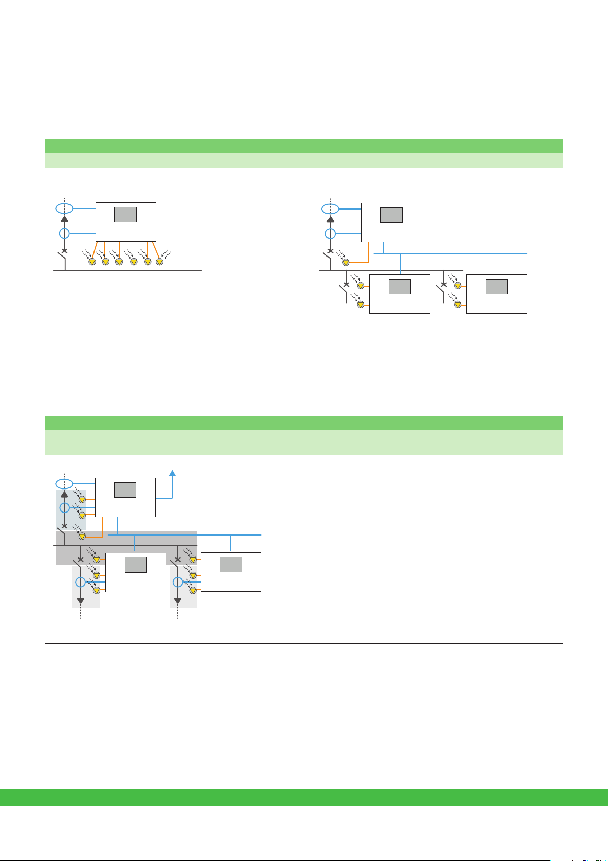
Arc-ash application
Busbar arc-flash protection
• Arc-flash protection, activated by overcurrent and light signals, or light signals alone
Centralized busbar arc-flash protection De-centralized busbar arc-flash protection
DM107114
P5F30
DM107115
P5F30
• Up to 6 light point sensors to monitor the busbar • Up to 6 light point sensors in each relay
• Transmission of light detection signals via digital I/O or
IEC 61850 GOOSE messages
P5F30P5F30
Zone arc-flash protection
• Up to 8 arc-flash protection stages in each device (P5x30)
• Transmission of signals via digital I/O or IEC 61850 GOOSE messages
In this application example, the arc-flash sensor for zone 3.1
is connected to Device 1. If the arc-flash sensor detects light
and simultaneously Device 3 detects and sends an overcurrent
condition, the zone 3.1 is isolated by the outgoing feeder breaker.
The arc-flash sensor for zone 3.2 is connected to Device 2 and
operates the same way.
The arc-flash sensors for zone 2 are connected to Device 1, 2,
or 3. If a sensor detects a flash in zone 3, the light-only signal is
DM107116
Zone 2
Zone 1
DEVICE 3
P5F30
Zone 1
light detection signal
transferred to Device 3, which then trips the main circuit breaker.
DEVICE 1
Zone 3.1 Zone 3.2
P5F30 P5F30
DEVICE 2
An eventual arc-flash fault in zone 1 does not necessarily activate
the current element in Device 3. However, arc-flash detection can be
achieved by using the light-only principle. If an arc-flash occurs in
the cable termination of zone 1, an inter-trip signal is sent by Device
3 to the upstream circuit breaker.
schneider-electric.com18 | Easergy P5 Catalog
Page 19
Easergy P5
Selection guide by application
Range description
Capacitor bank protection
• Overcurrent and earth/ground fault protection
• Overload protection
Capacitor bank protection without
voltage monitoring
DM107135
P5U20 P5F30
Capacitor application
Capacitor bank protection with voltage
monitoring
DM107136
P5F30
Protection of harmonic filters
DM107137
P5F30
P5U20
• Capacitor overvoltage protection, based on
current measurement and harmonics
• Current harmonic values and THD
• Capacitor bank unbalance
• Overvoltage
• Current and voltage harmonic values
and THD
• Overvoltage
• Capacitor bank unbalance
• Capacitor overvoltage protection, based
on current measurement and harmonics
• Current harmonic values and THD
schneider-electric.com | 19Easergy P5 Catalog
Page 20

Easergy P5
Range description
Motor overspeed - ANSI 12
The function is based on the direct measurement of motor speed. The overspeed protection function detects
racing when the motor is driven by the load, or a loss of synchronization for synchronous motors, or for process
monitoring. This function picks up if the speed measured exceeds the speed setting and it will trip after a
definite time delay.
• Two stages of overspeed protection with definite time delay
• The function is available when a 12 DI / 4 DO board is present and the motor speed detection function is
enabled.
Functions Settings
Motor speed setting range 10 – 160% Ωn
Definite time delay 1 s to 300 s
Motor underspeed - ANSI 14
Functions and description
The function is based on the direct measurement of motor speed. The underspeed protection function can
detect the slow-down of motor speed after motor starting, possibly resulting from mechanical overloads or
locked rotor. This protection is active after the motor speed has successfully achieved the speed setting. The
function picks up if the speed measured drops below the speed setting after having first exceeded the set point
by 5%. Under-speed protection is blocked when the motor speed drops below 5% of rated motor speed to avoid
unwanted tripping when the motor is switched off.
• Two stages of underspeed protection with definite time delay
• The function is available when a 12 DI / 4 DO board is present and the motor speed detection function is
enabled.
Functions Settings
Motor speed setting range 10 – 100% Ωn
Definite time delay 1 s to 300 s
Motor anti-backspin (ABS)
For a motor with high inertia, once the CB/Contactor supplying power to the motor is switched off, the rotor may
continue to turn for a considerable length of time. In that case, the motor terminal voltage is out of phase and
the motor re-starting operation may result in catastrophic failure. In some other applications for example when a
motor is on a down-hole pump, after the motor stops, the liquid may fall back down the pipe and spin the rotor
backwards. It would be very undesirable to start the motor at this time. In these circumstances the anti-backspin
function is used to detect when the rotor has completely stopped, to allow re-starting of the motor.
• One stage of anti-backspin protection with definite time delay
• This function is availaible when Motor Status function is enabled
• 3 different criteria for rotor stop detection
• Depending on criteria selected, a 12 DI / 4 DO board and the motor speed detection function may be
required.
Functions Settings
Rotor stop detection mode Zero speed, Zero speed switch, Motor stopped
Definite time delay 1 s to 7 200 s
schneider-electric.com20 | Easergy P5 Catalog
Page 21

Easergy P5
Functions and description
Range description
Fault locator - ANSI 21FL
The function can be used to locate a short-circuit fault and an earth/ground fault in radially operated networks.
The fault location is given as reactance (Ohms) and as distance in kilometers or miles. The fault value can then
be exported, for example, with an event to a Distribution Management System (DMS). The system can then
locate the fault. If a DMS is not available, the distance to the fault is displayed as kilometers and as a reactance
value.
Functions Settings
Pick-up 0.10 to 5.00 In
Line reactance 0.010 to 10.000Ohm/km
Earth/ground factor 0.000 to 10.000
Earth/ground factor angle
-60° to +60°
Neutral admittance - ANSI 21YN
The neutral admittance protection function can be applied in high resistance earthed, unearthed or
compensated power systems to detect earth fault with increased sensitivity. The neutral admittance Yn is
calculated based on the zero-sequence current I0 and the zero-sequence voltage U0.
• Two independent stages with definite time delay.
• Each stage settable for over-admittance or over-conductance or over-susceptance.
• Four setting groups.
Functions Settings
Pick-up for Yn
Pick-up for Gn
Pick-up for Bn
Directional mode Non-directional, Forward, Reverse
Operation delay 0.05 to 300 s
Reset time 0 to 100 s
(1)
SOL
operation Disable/Enable
(1)
SOL
operation delay 0.05 to 300 s
1% - 200% In/Un for current measured with very sensitive earth/ground fault CT
5% - 1000% In/Un for current measured by standard earth/ground fault CTs
5% - 1000% In/Un for current measured by standard earth/ground fault CTs
1% - 100% In/Un for current measured with very sensitive earth/ground fault CT
5% - 500% In/Un for current measured by standard earth/ground fault CTs
25% - 2500% In/Un for current measured by CSH and for calculated Io
1% - 100% In/Un for current measured with very sensitive earth/ground fault CT
5% - 500% In/Un for current measured by standard earth/ground fault CTs
25% - 2500% In/Un for current measured by CSH and for calculated Io
(1) SOL = Selective Overcurrent Logic
schneider-electric.com | 21Easergy P5 Catalog
Page 22

Easergy P5
Range description
Synchro-check - ANSI 25
This function checks the phase to phase voltages on both sides of a circuit breaker (CB) and allows CB closing
when the voltage phase angle, magnitude, frequency differences are all within permitted limits.
• Seven operation modes of no-voltage conditions are provided (dead line, dead bus).
• Synchronous mode is provided, where the frequency difference is less than 0.3 Hz.
• Asynchronous mode is provided, where CB close time is compensated.
• Independent settings for voltage phase angle, magnitude, frequency differences.
• Four setting groups.
Functions Settings
Synchronization mode Off, Asynchronous, Synchronous
Voltage check mode DD, DL, LD, DD/DL, DD/LD, DL/LD, DD/DL/LD
Circuit breaker close time 0.04 to 0.6 s
Dead line voltage setting limit 1% to 120% Un
Active line voltage setting limit 1% to 130% Un
Frequency difference 0.01 to 1.0 Hz
Voltage difference 1% to 60% Un
Phase angle difference 2º to 90º
Request timeout 0.1 to 600 s
Functions and description
(1)
(1) D = no-voltage condition, L = voltage condition
Under voltage - ANSI 27
This function is applied to detect abnormal system voltage decreases, to trigger automatic load shedding,
voltage source transfer, or trip out motor loads to avoid motor stall. This protection works with the minimum phase
to phase voltage.
• Three independent stages with definite time are provided.
• Low voltage self-blocking operates when the maximum phase to phase voltage is less than 10%Un.
• Four setting groups for each stage.
Functions Settings
Pick-up 20 to 120%Un
Hysteresis 0.1 to 20%
Delay type 0.03 to 300s
Adjustable reset 0.3 to 300s
schneider-electric.com22 | Easergy P5 Catalog
Page 23

Easergy P5
Functions and description
Range description
Positive sequence under voltage - ANSI 27P
This function is applied to detect insufficient or unbalanced system voltages and detect reverse rotation.
• Two independent stages with define time are provided.
• Low voltage self-blocking will operate when the maximum phase to phase voltage is less than 10% Un.
Functions Settings
Pick-up 20 % to 120%Un
Time delay 0.08 to 300.00s
Low voltage self-blocking 2 % to 100%Un
Directional active underpower - ANSI 32/37P
This function can be used as underpower protection (e.g. loss of load of a motor) or as reverse power protection
(e.g. power generation by a motor if supply is disconnected). It starts if measured active power drops below the
set threshold and operates with definite time delay.
• Two independent stages with definite time delay are provided
• Undervoltage blocking if the maximum phase to phase voltage is less than 5% Un.
• Four setting groups for each stage.
Functions Settings
Pick-up -200 % to 200 % Sn
Time delay 0.3 to 300.0 s
(1)
with Sn = √3 Un In
schneider-electric.com | 23Easergy P5 Catalog
Page 24

Easergy P5
Functions and description
Range description
Wattmetric earth/ground fault - ANSI 32N
This function detects single phase to earth/ground faults in Petersen coil compensated power systems. It
operates on active residual power. Using memory mode also allows operation on intermittent earth/ground faults.
• Neutral displacement voltage U0> element to enable function.
• Settable forward/reverse direction.
• Operating characteristic with settable minimum active power and sector angles.
• Dedicated blocking input.
• Dedicated input to bypass operate time delay.
• Four setting groups for each stage.
Functions Settings
Direction mode Reverse, forward
Setting range
Time delay 0.05 to 300.00s
U0> 2 % to 80 % Un
Sector angle 0° - 90°
Memory mode None, voltage, time, voltage+time
Memory hold time 0.05 to 10.00s
Memory operating time 0.00 to 100.00s
(1)
SOL
operation
(1)
SOL
operation delay 0.05 to 300.00s
0.1 % to 20 % Sn
Active, inactive
Phase undercurrent - ANSI 37
This function is typically used to detect defects in motor drives based on loss of load detection due to a
significant drop of current. It measures the fundamental component of the phase currents.
• One stage with definite time delay is provided.
• Low-current blocking if maximum current is less than 15% In.
• Four setting groups for each stage.
Functions Settings
Pick-up 20 % to 70 %
Time delay 0.3 s to 300 s
(1) SOL = Selective Overcurrent Logic
schneider-electric.com24 | Easergy P5 Catalog
Page 25

Easergy P5
Functions and description
Range description
Temperature monitoring - ANSI 38
This function is used to detect abnormal heat rise by directly measuring the temperature inside equipment
(transformer, motors, generators, …) with RTD thermal sensors such as Pt100, Ni100 or Ni120.
• Two independent set points: alarm and tripping for each RTD sensor.
• Inbuilt RTD supervision (shorting, open loop).
Functions Settings
Pick-up 0 to 180°C (32 at 356°F)
Time delay 0.3 to 600.0 s
Negative sequence overcurrent - ANSI 46
This function provides greater sensitivity to detect phase to phase faults at the end of long lines or behind
transformers. It can also be used for machine protection (against temperature rise caused by unbalanced power
supplies, phase inversion, or loss of phase).
• One stage with definite time or inverse time delay
• Four setting groups.
Functions Settings
Pick-up 0.02 to 5.00In
Definite time delay
Inverse time delay curves
Inverse time coefficient
0.07 to 300.00s
IEC: NI, VI, EI, LTI
IEEE: VI, EI, LTI, LTEI, LTVI, MI, STI, STEI
IEEE2: NI, VI, EI, MI
Others: RI, RXIDG
Programmable: 3 curves with 16 setting points
0.05 to 20.00 for IEC curves and others (RI)
0.5 to 20.0 for IEEE, IEEE2 curves and others (RXIDG)
schneider-electric.com | 25Easergy P5 Catalog
Page 26

Easergy P5
Functions and description
Range description
Unbalanced overcurrent, broken conductor - ANSI 46BC
This function is applied to detect broken conductor conditions, based on the ratio between the negative
sequence current and positive sequence current.
• One stage with definite time delay is provided.
• This function is not available in 2CT mode.
• Four setting groups.
Functions Settings
Pick-up 2 to 70%
Time delay
0.07 s to 300s
Negative sequence overvoltage - ANSI 47
Protection of a rotating machine from being energized with a reverse voltage sequence or prevention of
overheating of the motor due to a broken conductor condition. It monitors the voltage phase sequence
detecting a reverse rotation or voltage unbalance due to a missing (asymmetrical) phase. The detection of these
conditions can then be used to trip the machine to prevent damage to both motor and any mechanically coupled
processes.
• Two independent stages with definite or inverse time delay.
• When the VT connection is configured to LL/LLy the function is automatically disabled.
• Four setting groups for each stage.
Functions Settings
Pickup value 1% Un - 100% Un
Delay type Definite time (DT), inverse time (INV)
Operation delay 0.08 s to 300 s
Reset time 0.03 s to 300 s
schneider-electric.com26 | Easergy P5 Catalog
Page 27

Easergy P5
Functions and description
Range description
Motor start-up supervision - ANSI 48
Protection of motors against overheating caused by excessive start time due to heavy motor load or too low
voltage.
• Motor start detection is based on circuit breaker (CB) position and current.
• Operation with definite time delay or inverse time delay.
Functions Settings
Motor start detection current 1.3 to 10.0In
Motor start detection mode CB position, current, CB position and current
Delay type Definite time (DT), inverse time (INV)
Motor start time 1 s to 300.0s
Thermal overload protection for feeders - ANSI 49F
This function is applied to detect conditions where thermal damage may be caused by overloads on cables. The
thermal capacity is calculated by the thermal replica according to IEC60255-149. The equivalent current for the
thermal replica is the maximum RMS current of 3 phases.
• Independent settable alarm stage and trip stage are provided.
• Current based setting mode and temperature based setting mode are provided.
• Temperature sensor can be applied for ambient temperature based mode.
• A digital input can be applied to inhibit the thermal overload protection
• Four setting groups are provided.
Functions Settings
Basic current setting
k factor 0.10 to 1.50
Heating time constant 1.0 min to 1000 min
Thermal alarm value 50 % to 100 %
Reserve time thermal alarm 1.0 min to 1000 min
Temperature based mode Current, Ambient
Nominal ambient temperature
Max object temperature -40 ºC to 300 ºC
Alarm object temperature 0 ºC to 300 ºC
Min object temperature -40 ºC to 300 ºC
Default object temperature -40 ºC to 300 ºC
Thermal level initiation 0 to 90%
0.10 In to 4.00 In
-40 ºC to 300 ºC
schneider-electric.com | 27Easergy P5 Catalog
Page 28

Easergy P5
Functions and description
Range description
Thermal overload protection for motor - ANSI 49M
This function is applied to detect conditions where thermal damage may be caused by overloads on motors or
cables. The thermal capacity is calculated by the thermal replica according to IEC 60255-149. The equivalent
current for the thermal replica considers the maximum RMS current of 3 phases and the negative phase
sequence current with a settable weighting coefficient.
• Independent settable alarm stage and trip stage are provided.
• Current based setting mode and temperature based setting mode are provided.
• Temperature sensor can be applied for ambient temperature based mode.
• A digital input can be applied to inhibit the thermal overload protection
• Four setting groups.
Functions Settings
Basic current setting 0.1 In to 4.0 In
k factor
Heating time constant
Time constant for motor start 1.0 min to 1000 min
Cooling time constant 1.0 min to 1000 min
Thermal alarm value 50% to 100%
Reserve time thermal alarm 1.0 min to 1000 min
Temperature based mode Current, Ambient temperature
Nominal ambient temperature -40 ºC to 300 ºC
Max object temperature -40 ºC to 300 ºC
Alarm object temperature 0 ºC to 300 ºC
Min object temperature -40 ºC to 300 ºC
Default object temperature -40 ºC to 300 ºC
Thermal level initiation 0 to 90%
Unbalance factor 0 to 10
1.0 to 1.5
1.0 min to 1000 min
schneider-electric.com28 | Easergy P5 Catalog
Page 29

Easergy P5
Range description
Arc-flash - ANSI 50ARC
This function is used to detect and minimize the effects of an internal arcing fault, commonly by tripping the CB
faster than conventional protection to mitigate the fault.
• Eight independent arc-flash stages.
• GOOSE communication to share informations between two Easergy P5 relays.
• Three to six arc-flash sensors available.
• Trip in 4 ms maximum if light detection only.
• Trip in 15 ms maximum if light detection and overcurrent conditions detected with GOOSE communication
between two Easergy P5 relays.
Functions Settings
Arc-flash stage 1 to 8 On, Off
Detection mode
Pick-up phase current 0.50 to 8.00 In
Pick-up ground/earth current 0.10 to 5.00
Trip delay
Hold time 20 ms to 2500 ms
Functions and description
Light, light + current
0 ms to 255 ms
Breaker failure - ANSI 50BF
The circuit breaker failure function (CBF) can be used to operate any upstream circuit breaker (CB) if the
programmed output signals, to the main breaker, have not disappeared within a given time after the initial
command.
• Two circuit breaker controls are available.
Functions Settings
Phase current pick-up 0.02 to 4.00 In
Earth/ground current pick-up
Very sensitive earth/ground current
pick-up
Time delay 0.02 s to 50.00s
0.02 to 4.00 Ino with 1/5 A standard CT
0.05 to 4.00 Ino with CSH core balance CT
0.002 to 4.000 Ino
schneider-electric.com | 29Easergy P5 Catalog
Page 30

Easergy P5
Functions and description
Range description
Switch onto fault (SOTF) - ANSI 50HS
This function is applied to provide fast tripping based on instantaneous overcurrent protection, when the CB is
closed onto a faulted line.
• One stage instantaneous overcurrent is provided.
• CB open/dead line detection is based on a low current threshold 0.02 In or digital input.
• SOTF active duration after CB closure is settable.
Functions Settings
Pick-up 1.0 to 40.0In
Dead line detection delay
SOTF active time 0.1 to 60.0s
0 to 60.0s
Cold Load Pick-up (CLP)
This function helps avoid unwanted tripping of overcurrent protecton elements (50/51, 50N/51N, 50G/51G and
67) during energisation after long periods of outage. Depending on installation characteristics such operations
can generate inrush currents that can exceed the pick-up level of protection. These inrush currents may be
caused by:
• • Magnetizing currents of power transformers.Magnetizing currents of power transformers.
• • Motor starting currents.Motor starting currents.
• • Simultaneous re-energization of the entire facility load (air conditioning, heating...).Simultaneous re-energization of the entire facility load (air conditioning, heating...).
In principle the protection settings should be defined in order to avoid tripping on such inrush currents. In principle the protection settings should be defined in order to avoid tripping on such inrush currents.
However if the settings result in insufficient sensitivity levels or too long delays, the CLP function can be used to However if the settings result in insufficient sensitivity levels or too long delays, the CLP function can be used to
temporarily increase or inhibit thresholds after re-energization.temporarily increase or inhibit thresholds after re-energization.
Functions Settings
Pick-up
Definite time delay
Inverse time delay curves
Inverse time coefficient(k )
0.02to 20.0In
0.03 to 300.00s
IEC, IEEE, IEEE2, Others, 3 programmable curves
0.05 to 20.00 for IEC curves and others (RI)
0.5 to 20.0 for IEEE, IEEE2 curves and others (RXIDG)
schneider-electric.com30 | Easergy P5 Catalog
Page 31

Easergy P5
Functions and description
Range description
Phase overcurrent - ANSI 50/51
These functions are used to detect short circuit faults and heavy overloads. The overcurrent function measures
the fundamental frequency components (1st harmonic) of the phase currents. The protection is sensitive to the
highest of the three phase currents. Whenever this value exceeds the user’s start setting of a particular stage, a
start signal is issued. If the fault situation remains present longer than the operation delay setting, a trip signal is
issued.
• Two stages ((I> and I>>) with definite time or inverse time delay.
• One stage (I>>>) with definite time delay and a maximum starting time of 20 ms (P5x30).
• Cold load pick-up function.
• Four setting groups for each stage.
Functions Settings
I> 0.05 to 20.00 In
Definite time
(DT) pick-up
Inverse time
(IDMT) pick-up
Definite time delay 0.03 to 300.00 s
Inverse time delay curves
Inverse time coefficient(k)
Reset time 0.03 to 100.00 s
I>>
I>>>
I> 0.05 to 5.00 In
I>> 0.10 to 5.00 In
0.10 to 20.00 In
0.10 to 40.00 In
IEC : NI, VI, EI, LTI
IEEE : VI, EI, LTI, LTEI, LTVI, MI, STI, STEI, others
IEEE2 : NI, VI, EI, MI
Others : RI, RXIDG
Programmable : 3 curves with 16 setting points
0.05 to 20.00 for IEC curves and others (RI)
0.5 to 20.0 for IEEE, IEEE2 curves and others (RXIDG)
schneider-electric.com | 31Easergy P5 Catalog
Page 32

Easergy P5
Functions and description
Range description
Earth/ground fault overcurrent - ANSI 50N/51N and ANSI 50G/51G
Earth/ground fault protection (ANSI 50N/51N) is based on the measured residual current from a 1A/5A standard
CT or CSH core balance CT. Alternatively, it can also apply the calculated residual current.
Sensitive earth/ground fault protection (ANSI 50G/51G) is based on measured residual current with very
sensitive 1 A standard CT.
• ANSI 50N/51N - Two stages with definite and inverse time delay and three stages with definite time delay.
• ANSI 50G/51G - Two stages with definite and inverse time delay and one stage with definite time delay.
• Cold load pick-up.
• Selective overcurrent logic settable for the first four stages.
• Four setting groups for each stage.
Functions Settings
Io (ANSI 50N/51N)
Io’ (ANSI 50G/51G)
Io>, Io’>,
Io>>, Io’>>
Definite time
(DT) pick-up
Inverse time
(IDMT) pick-up
Definite time delay 0.03 to 300s
Inverse time delay curves
Inverse time coefficient(k)
Reset time
Io>>>, Io’>>>,
Io>>>>
Io>>>>> 0.05 to 10.00 Ino
Io>, Io’>,
Io>>, Io’>>
Measured with 1 A/5 A CT
Measured with 1 CSH core balance CT
Calculated with the sum of the 3 phase currents
Measured with 1 A CT
CT CSH core balance CT Calculated earth/ground fault
0.02 to 10.00 Ino 0.05 to 10.00 Ino 0.05 to 20.00 In
0.02 to 20.00 Ino 0.05 to 20.00 Ino 0.05 to 20.00 In
- -
0.02 to 5.00 Ino 0.05 to 5.00 Ino 0.05 to 5.00 In
IEC: NI, VI, EI, LTI
IEEE: VI, EI, LTI, LTEI, LTVI, MI, STI, STEI
IEEE2: NI, VI, EI, MI
Others: RI, RXIDG
Programmable : 3 curves with 16 setting points
0.05 to 20.00 for IEC curves and others (RI)
0.5 to 20.0 for IEEE, IEEE2 curves and others (RXIDG)
0.03 to 100s
schneider-electric.com32 | Easergy P5 Catalog
Page 33

Easergy P5
Functions and description
Range description
Capacitor bank unbalance - ANSI 51C
This function is used in double-wye-connected capacitor banks. The unbalance current is measured with a
dedicated current transformer (i.e. 5A/5A) between two starpoints of the bank.
• Two stages with definite time delay.
• Unbalance current measured with standard earth/ground fault CT or CSH core balance CT.
• Four setting groups for each stage.
Functions Settings
Pick-up
Time delay 0.03 to 300 s
0.02 to 10.00 Ino for standard CT
0.05 to 10.00 Ino for CSH core balance CT
Locked rotor - ANSI 51LR
Protection of motors against overheating caused by motor rotor jam due to heavy motor load or a mechanical
failure after the normal start.
• Operation with definite time delay or inverse time delay.
• Automatically blocked when the motor is starting.
Functions Settings
Pick-up 10 to 100.0%IStart
Time delay 1 to 300.0s
Time delay type
Overvoltage - ANSI 59
This function is applied to detect an abnormal higher system voltage or to check sufficient voltage for voltage
source transfer. This protection works with the maximum phase to phase voltage.
• Three independent stages with definite time delay are provided.
• Four setting groups for each stage.
Functions Settings
Pick-up 50 to 150%Un
Hysteresis 0.1 to 20%
Trip 0.04 to 300s
Hold 0.03 to 300s
Definite time (DT), Inverse time (INV)
schneider-electric.com | 33Easergy P5 Catalog
Page 34

Easergy P5
Functions and description
Range description
Capacitor overvoltage - ANSI 59C
This function calculates the voltages of a three-phase Y-connected capacitor bank using the measured currents
of the capacitors. No voltage measurements are needed.
Especially used in filter applications, harmonics are present, which depending on phase angles, can increase
the peak voltage. This protection function calculates the worst-case overvoltage in per-unit values using Equation
7.10 according to IEC 60871-1 standard. Harmonics up to 15th are taken into account.
• Three independent stages with define time.
• Four setting groups.
Functions Settings
Pick-up setting UC> 0.10 to 2.50UCLN
Time delay 1.0 to 30.0s
Rated L-N voltage UCLN 100 to 260000V
Capacitance per phase
1.00 to 650.00μF
Neutral voltage displacement - ANSI 59N
This function is used for general earth/ground fault detection and for backup protection (unselective). It
measures the fundamental component of the neutral displacement voltage.
• 3 stages with DT operating time
• Attenuation of the third harmonic by more than 60 dB
• Faster high-set stage U0>>>.
• 4 setting groups for each stage.
Function Settings
Pick-up 2 to 120% Uno
Time delay 0.04 s to 300.00s
Motor restart inhibition - ANSI 66
This function prevents too frequent motor starts. Every motor has a restriction on the number of starts within
a defined period to avoid thermal overload, mainly inside the rotor. A settable time interval between two
consecutive starts is also necessary to allow the motor to cool down following the previous start.
• Settable number of starts per hour.
• Settable minimum time between consecutive starts.
Functions Settings
Time from motor start 0min, 120min
Maximum hot starts / hour 1 to 20
Maximum cold starts / hour 1 to 20
Minimum time between starts 0.0 min to 100.0min
schneider-electric.com34 | Easergy P5 Catalog
Page 35

Easergy P5
Functions and description
Range description
Directional phase overcurrent - ANSI 67
This function provides directional short circuit protection.
• Four independent stages with definite time delay (DT), two of them with inverse time delay (IDMT).
• Settable directionality
• Directional voltage memory with fixed duration of 3.2 s.
• Cold Load Pickup (CLP).
• Four setting groups for each stage.
Functions Settings
Direction mode
Definite time
(DT) pick-up
Inverse time
(IDMT) pick-up
Definite time delay 0.03 to 300.00 s
Inverse time delay curves
Inverse time coefficient(k)
Reset time 0.03 s to 100.00 s
Angle offset
I>
I>> 0.10 to 20.00 In
I>>> 0.10 to 40.00 In
I> 0.05 to 5.00 In
I>> 0.10 to 5.00 In
Directional
Non directional
Directional + Backup
0.05 to 20.00 In
IEC: NI, VI, EI, LTI
IEEE: VI, EI, LTI, LTEI, LTVI, MI, STI, STEI, others
IEEE2: NI, VI, EI, MI
Other : RI, RXIDG
Programmable: 3 curves with 16 setting points
0.05 to 20.00 for IEC curves and others (RI)
0.5 to 20.0 for IEEE, IEEE2 curves and others (RXIDG)
-180° to +179°
schneider-electric.com | 35Easergy P5 Catalog
Page 36

Easergy P5
Functions and description
Range description
Directional earth/ground fault overcurrent - ANSI 67N
This function provides selective and sensitive earth/ground fault protection for various network earthing systems
of power neworks.
• Residual current and voltage can be either measured or internally calculated based on phase currents and
voltages.
• Three independent stages with definite time and inverse time delay.
• Directional voltage memorywith fixed duration of 3.2 s.
• Settable directionality.
• Four setting groups for each stage.
Functions Settings
Io - Measured with 1 A/5 A CT
Io / Io’
Definite time (DT) pick-up 0.02 to 10.00 Ino 0.05 to 10.00 Ino 0.05 to 20.00 In 0.002 to 1.00 Ino
Inverse time (IDMT) pick-up 0.02 to 5.00 Ino 0.05 to 5.00 Ino 0.05 to 5.00 In 0.002 to 1.00 Ino
Definite time delay 0.03 to 300s
Inverse time delay curves
Inverse time oefficient(k)
Residual voltage Uo 1 to 50% Uno
Directional mode Resistive, capacitive, sector, non directional
Offset angle -180° to +179°
Io - Measured with 1 CSH core balance CTIo -
Io - Calculated with the sum of the 3 phase currents
Io’ - Measured with 1 A CT
Standard CT
IEC: NI, VI, EI, LTI
IEEE: VI, EI, LTI, LTEI, LTVI, MI, STI, STEI
IEEE2: NI, VI, EI, MI
Others: RI, RXIDG
Programmable: 3 curves with 16 setting points
0.05 to 20.00 for IEC curves and others (RI)
0.5 to 20.0 for IEEE, IEEE2 curves and others (RXIDG)
TCSH core
balance CT
Calculated
earth/ground fault
Very sensitive CT
schneider-electric.com36 | Easergy P5 Catalog
Page 37

Easergy P5
Functions and description
Range description
Transient intermittent earth/ground fault - ANSI 67NI
This function detects short transient intermittent phase to earth/ground faults in compensated networks, which
cannot be correctly recognized by steady-state directional earth/ground fault functions using the fundamental
frequency components only.
• Neutral displacement voltage U0> element to enable function.
• Settable forward/reverse direction.
• Dedicated blocking input to coordinate with AR.
• Four setting groups.
Functions Settings
Io Io measured with standard earth/ground fault CT or CSH core balance CT
Io’ Io’ measured with very sensitive earth/ground fault CT
Direction mode
Minimum of number of peaks 1 to 20
U0> setting
Time delay
Memory hold time 0,01 to 300.00s
Reset time 0.06 to 300.00s
Reverse, Forward
1 to 60% Uno
0.02 to 300.00s
2nd harmonic (H2) detection - ANSI 68H2
This function detects inrush current flows that occur when transformers or machines are energized. It may be
used to stabilize protection functions (e.g. phase overcurrent, earth/ground fault overcurrent, …) or even to issue
a trip if the inrush condition persists too long.
• Based on proven I2/I1 measurement.
• Measurement per phase.
Functions Settings
Pick-up 10 to 100%
Time delay 0.03 to 300.00s
5th harmonic (H5) detection - ANSI 68H5
This function detects 5th harmonic current flows that occur during overexcitation of transformers. It may be used
to stabilize protection functions or even to trip if the condition persists too long.
• Based on proven I5/I1 measurement.
• Measurement per phase.
Functions Settings
Pick-up 10 to 100%
Time delay 0.03 to 300.00s
schneider-electric.com | 37Easergy P5 Catalog
Page 38

Easergy P5
Functions and description
Range description
Auto-recloser function - ANSI 79
The auto-recloser (AR) function can be used in feeder protection relays to help protect an overhead line. It limits
the interruption of service in case of transient or semi-permanent faults that affect overhead lines. The function
uses the object control function to control the CB open/close sequence. All other object control methods are in
simultaneous use, including object failure monitoring. If the circuit breaker (CB) control fails or another function
controls the CB, the AR sequence stops.
• One to four autorecloser shots.
• Control of one or two circuit breakers.
• Control via binary or virtual inputs (IEC 61850).
Functions Settings
Enable Auto-Recloser
Breaker 1 object
Breaker 2 object
Auto CB selection On; Off
Input for CB selection
Reclaim time 0.02 to 3000.00s
Block by external synchro. check digital input (DI), virtual input (VI), virtual output (VO) or function key
Shot specific reclaim time On; Off
Settings per shot
Additional setting 1st shot 0.02 to 300.00s (start delay)
On; Off
with digital input (DI), virtual input (VI), virtual output (VO) or function key
Object 1 to Object 6
Object 1 to Object 6
digital input (DI), virtual input (VI), virtual output (VO) or function key
0.01 to 1200.00s (dead time)
0.02 to 300.00s (discrimination time)
Under and Over frequency - ANSI 81
Frequency deviations result from an imbalance between power generation and power loads. The over/under
frequency protection function is used for load shedding, loss of power system detection, load restoration and as
a backup protection for overspeeding in generators.
• Two independent stages with definite time delay are provided.
• The function is activated with a settable voltage threshold.
• Automatically inhibited if the maximum phase to phase voltage goes below the setting threshold.
• Four setting groups for each stage.
Functions Settings
Trip condition Under, over
Pick-up 40 to 70Hz
Time delay 0.1 s to 300s
Low voltage blocking 30 to 100%Un
schneider-electric.com38 | Easergy P5 Catalog
Page 39

Easergy P5
Functions and description
Range description
Rate of change of frequency - ANSI 81R
This function (ROCOF) is appliced to detect the rate of change of system frequency, for fast load shedding or
fast disconnection of islanded generators under loss of main condition.
• Two independent stages with definite time delay.
• Direction of the frequency change is settable.
• Automatically inhibited if the maximum phase to phase voltage goes below the setting threshold.
• Four setting groups for each stage.
Functions Settings
Direction of change Negative, Positive, Either
Pick-up 0.1 to 10Hz/s
Time delay 0.05 to 10s
Low voltage blocking 30 to 100%Un
Under frequency - ANSI 81U
This function is applied to detect an abnormally low system frequency, to trigger load shedding, or indicate the
loss of main grid.
• Four independent stages with definite time delay are provided.
• Automatically inhibited if the maximum phase to phase voltage goes below the setting threshold.
• Four setting groups for each stage.
Functions Settings
Pick-up 40 to 64Hz
Time delay 0.1 s to 300s
Low voltage blocking 30 to 100%Un
schneider-electric.com | 39Easergy P5 Catalog
Page 40

Easergy P5
Functions and description
Range description
Lockout - ANSI 86
The lockout feature, also called latching, ensures that a manual intervention is required to reset all alarm or
tripping conditions, for example to enable CB re-closing. It can be programmed in the output matrix setting view.
Any protection stage start or trip, digital input, logic output, alarm and GOOSE signal connected to the following
outputs can be latched when required:
• Output contacts.
• LEDs on the local panel.
• Virtual outputs.
Programmable stages - ANSI 99
For special applications the user can build their own detection stages by selecting the supervised signal and the
comparison mode. This allows the user to trigger an event from a selection of signals and select the type, level
and timing to suit the application.
• Eight independent stages with definite time delay.
• Priority selection for fast operation needs.
• Multiple coupling and comparison conditions.
• Four setting groups for each stage.
Functions Settings
Phase currents and earth/ground currents,
Simple or composed voltages,
Coupling
Trip conditions Under, over, dif ference, absolute difference
Time delay 0,08 to 300 s
Cuurent and voltage distortion values,
Direct current or voltage,
Inverse current or voltage,
Phase and earth/ground effective current
schneider-electric.com40 | Easergy P5 Catalog
Page 41

Easergy P5
Functions and description
Range description
Selective Overcurrent Logic (SOL)
The Selective Overcurrent Logic (SOL) function, can considerably reduce the tripping time of the circuit breakers
closest to the source, compared to pure time discrimination, and may be used for logic discrimination in closed
ring networks also using directional protection. SOL function is applied to the phase overcurrent, directional
phase overcurrent, earth/ground fault overcurrent (except stage 5), very sensitive earth/ground fault overcurrent
protection elements, with definite time and inverse time delays.
The selective overcurrent logic allows:
• To send a blocking signal when a fault is detected by overcurrent or earth/ground fault protection elements
(ANSI 50/51, 50N/51N, 50G/51G, 67, 32N).
• To receive a blocking signal that inhibits the protection elements.
Functions Settings
Definite time delay 0.03 to 300s
Inverse time delay curves IEC, IEEE, IEEE2, others, three programmable curves
Inverse time delay coefficient
0.05 to 20.00 for IEC curves and others (RI)
0.5 to 20.0 for IEEE, IEEE2 curves and others (RXIDG)
Circuit Breaker (CB) monitoring
Periodic maintenance of circuit breakers is necessary to ensure that the trip circuit and mechanism operate
correctly and that the interrupting capability has not deteriorated due to previous fault interruptions. The Easergy
P5 protection relay records various statistics related to each circuit breaker operation, allowing an accurate
assessment of the circuit breaker condition. Statistics are recorded to allow evaluation of both the electrical wear
of the breaker contacts and the mechanical wear of the breaker mechanism.
Following counters are provided:
• Number of all circuit breaker operations.
• Number of circuit breaker operations triggered by protection functions e.g. faults.
• Cumulative broken current.
• Circuit breaker operating times.
• Charging times.
• Number of rack-in and rack-out operations.
This feature, when paired with EcoStruxure Asset Advisor brings a proactive maintenance approach to electrical
distribution critical assets, combining newest technologies with Schneider Electric’s expertise and services.
EcoStruxure Asset Advisor offers the ability to anticipate and address issues before they become critical
incidents, mitigating safety risks, avoiding unplanned downtime, operational losses and expensive maintenance
interventions.
schneider-electric.com | 41Easergy P5 Catalog
Page 42

Easergy P5
Communication
Range description
HMI/
SCADA
DM107138
Serial
link
DM107139
Daisy chain
HMI/
SCADA
Examples of architectures
Connection to SCADA using serial line
This architecture allows you to connect HMI/SCADA to a set of Easergy P5
protection relays using a multi-drop serial communication link with master-slave
communication.
Available protocols:
• Modbus RTU
• IEC 60870-5-101
Time synchronization protocol:
• IRIG-B
• Minute pulse
• IEC 60870-5-103
• DNP3
Connection to SCADA using Ethernet
This architecture allows you to connect a set of Easergy P5 protection relays
directly to an Ethernet network.
Available protocols:
• IEC 61850 Edition 1 and Edition 2
• DNP3
• EtherNet/IP
• Modbus TCP/IP
Ethernet
switch
DM107140
SubNetwork
Panel
HMI
Ethernet
GOOSE
messages
Ethernet
switch
Ethernet
switch
Ethernet
Network
GOOSE
messages
Easergy
Pro
Note: It is possible to mix IEC 61850 protocol with other communication or
redundancy protocols from Easergy P5 on the same Ethernet network. This allows
you to use GOOSE messages between relays together with another protocol for
communication to SCADA. It is also possible to connect to two different control
systems, using the same Ethernet communication port and IEC 61850 protocol for
one network, and any available protocol for the second network.
Equipped with two Ethernet modules, Easergy P5x30 can handle 3 Ethernet
protocols simultaneously with a single IP or 3 different IP adresses. Optionally,
Easergy P5x30 offers a capability of dual redundancy providing PRP/HSR protocol
for one system and a separate RSTP protocol for another system or engineering
channel.
Easergy P5 protection relay handles the IEC 61850 station bus, in compliance with
IEC 61850-6, 7-1, 7-2, 7-3, 7-4 and 8-1 Edition 1 or Edition 2 standards, according
to the configuration.
Other available Ethernet protocols:
• FTP for file transfer
• SNTP for time synchronization
• PTP for precise time synchrionisation according to IEEE 1588v2 standard
• HTTPs for web server (setting changes)
Switchboard internal network
This architecture allows fast GOOSE communication between Easergy protection
relays in the same switchboard, this avoiding costly wiring. Typical uses are logic
discrimination, load shedding, etc.
In addition, a panel HMI featuring a web browser can be used to monitor and
control the entire switchboard.
A spare connection on the panel Ethernet switch can also be provided for
connecting the eSetup Easergy Pro setting and configuration tool.
On Easergy P5x30 models, two independent Ethernet communication modules are
available. This allows implementation of the switchboard internal network and the
communication to SCADA on two separate Ethernet networks.
schneider-electric.com42 | Easergy P5 Catalog
Page 43

Easergy P5
Communication
Range description
DM107141
Ethernet
switch
Ethernet
switch
HMI/
SCADA
Ethernet
switch
Ethernet
switch
Redundancy protocols
RSTP (Rapid Spanning Tree Protocol)
The principle of RSTP is to virtually remove all links that are not necessary at a
given time, changing the meshed topology into a tree topology.
The main advantage of RSTP is that it is widespread and works on any network
topology. On the other hand, RSTP takes milliseconds or seconds to reconfigure the
network in case of network interruption.
With Easergy P5, the typical reconfiguration time for a loop of 10 relays is 0,050s.
HMI/
DM107142
Network A
Network
DM107143
Easergy P5 Easergy P5 Easergy P5
SCADA
Ethernet
switch
Network B
PRP (Parallel Redundancy Protocol)
The principle of PRP is to transmit frames in parallel on two independent network
infrastructures: A and B.
The receiving device is in charge of removing the redundant frame, if it has already
been received.
PRP protocol provides an instantaneous recovery time in case of failure, since no
re-transmission of the message is needed.
HSR (High-availability Seamless Redundancy)
HSR is similar to PRP but only works on a ring architecture.
Frames are transmitted on the ring in both directions and the receiving device
eliminates redundant frames.
HSR protocol provides an instantaneous recovery time and is an alternative to PRP
when network topology is restricted to a ring.
Both PRP and HSR protocols are listed in IEC 62439-3 as part of IEC 61850
standard. They both provide standardized, interoperable and high performance
redundant Ethernet solutions.
schneider-electric.com | 43Easergy P5 Catalog
Page 44

Easergy P5
Communication
Range description
Easergy P5 protection relays
offer following solutions for time
synchronization:
Communication protocol, Minute Pulse,
IRIG-B, SNTP and PTP.
IRIG-B Master
DM107460
Switch
Ethernet IED Serial IED
IRIG-B
Cabling
Separate
from
Data Network
Time synchronization
In modern protective schemes it is required to synchronize the internal realtime clock of the relay, so that events from different relays can be placed in
chronological order.
This can be done using the communication interfaces connected to the substation
control system or via dedicated time synchronization options provided by Easergy
P5 relays: minute pulse, IRIG-B time code and SNTP or PTP IEEE 1588v2 over
Ethernet networks.
Minute pulses
The clock can be synchronized by reading minute pulses from digital inputs, virtual
inputs or virtual outputs. The sync source is selected with the SyncDI setting.
When a rising edge is detected from the selected input, the system clock is
adjusted to the nearest minute.
IRIG-B
Inter-Range Instrumentation Group time code B (IRIG-B) is a standard format for
transferring timing information. IRIG-B time synchronization standard is based on a
frame of 100 data bits sent every second to the device.
This time synchronization standard is supported in Easergy P5 by the IRIG-B
module connected to the optional extension module of the relay.
The module provides both a modulated and an unmodulated input and can
automatically detect which input type is used. The time synchronization accuracy in
Easergy P5 with this mode is less than 5 ms. For more information, see the IRIG-B
module details so page 89.
DM107461
GPS clock as SNTP master
DM107462
PTP Grandmaster
HMI/
SCADA
Ethernet
switch
SNTP Protection Relays
HMI/
SCADA
Transparent Clock
(PTP Ethernet switch)
PTP Protection Relays
Substation HMI
with SCADA gateway
Substation HMI
with SCADA gateway
SNTP
Simple Network Time Protocol (SNTP) is a less complex implementation of Network
Time Protocol (NTP), using the same protocol but without requiring the storage of
state over extended periods of time. SNTP is used to synchronize the clocks of
computer systems over packet switched, variable-latency data networks.
A jitter buffer is used to reduce the effects of variable latency introduced by
queuing in packet switched networks, ensuring a continuous data stream over the
network.
The Easergy P5 protection relay receives the synchronization from the SNTP/NTP
server. The time synchronization accuracy in this mode is less than 5 ms.
PTP
Precision Time Protocol according to IEEE 1588-2008 (v2) standard. The
PTP implementation in Easergy P5 protection relay is compliant to IEC618509-3 standard. This protocol enables precise synchronization of clocks in
measurement and control systems implemented with technologies such as network
communication, local computing, and distributed objects.
The protocol is applicable to systems communicating via Ethernet. Systemwide
synchronization accuracy and precision in the sub-microsecond range are
supported with minimal network and local clock computing resources. The time
synchronization accuracy in Easergy P5 with this mode is less than 1 ms.
schneider-electric.com44 | Easergy P5 Catalog
Page 45

Easergy P5
Communication
Range description
Data exchanged
Data exchanged with SCADA
Ports Ethernet Serial or Ethernet Serial
Protocol
Real time data
Measurement -
Alarms and status -
Controls -
Time-stamped events -
Historical data
Disturbance records
Sequence of event record files - - - - -
Setting management
Setting group change -
Settings - - - -
IEC 61850 Ethernet/IP FTP DNP3 Modbus
- -
-
IEC 60870-
5-103
IEC 60870-
5-101
-
-
Data exchanged according to IEC 61850
The Methodology described in the IEC 61850-6 standard can be applied with
Easergy P5 protection relays, in order to build a protection and control system
based on this standard.
.icd file
For each model of Easergy P5 relay, the IED capability file can be downloaded
from the Schneider Electric website.
.scd file
The system description file generated by the system configurator can be
processed by eSetup Easergy Pro and the relevant system settings integrated in
the Easergy P5 configuration.
DM107144
Safe Repository and
Schneider Electric website
.icd file
System
configurator
.iid file.scd file
eSetup
Easergy Pro
.iid file
When the configuration of an Easergy P5 protection relay is completed or
modified, eSetup Easergy Pro can generate an Instantiated IED Description file to
be used by the system configurator to update the system description.
schneider-electric.com | 45Easergy P5 Catalog
Page 46

Easergy P5
Cybersecurity
Range description
Cybersecurity features implemented in
Easergy P5 help to mitigate cyber threats.
Easergy P5 can be ordered, either with:
- Cybersecurity basic level or
- Cybersecurity advanced level.
More info on the Schneider Electric
Cybersecurity Support portal:
www.se.com/ww/en/work/support/
cybersecurity/overview.jsp
Cybersecurity - Basic Level
Cybersecurity
Cybersecurity in the scope of energy management is a set of rules, methods, and
technical features intended to improve the quality of service and minimize risk of
interruption of deliveries, resulting from accidental or intentional actions.
The Easergy P5 protection relay is designed with special attention to cybersecurity
aspects, with compliance to Schneider Electric’s Cybersecurity Policy and
following Secure Development Lifecycle process.
All these efforts have been proved in obtaining certificates of Level 1 and Level 2 of
Achilles Communications Certification Standard.
Depending on customer needs, the Easergy P5 protection relay can be ordered
with Cybersecurity Basic Level or Advanced Level. This selection must be made at
ordering stage.
Cybersecurity Basic Level
The features available for Basic Level are also found in the Advanced Level.
• Secured communication between Easergy P5 protection relays and associated
tools.
• Protection of the hardware and logical communication ports.
• Firmware signature.
• Password based user authentication.
• Role Based Access Control (RBAC) authorization management.
• Secured log storage.
• Client IP address filter
• Compliance to NERC CIP and BDEW standard requirements.
schneider-electric.com46 | Easergy P5 Catalog
Page 47

Easergy P5
Cybersecurity
Range description
PM108582
DM107145
Security logs Security configuration
Security
logs
request
CAE tool
Cybersecurity - Advanced Level
Cybersecurity Advanced Level with
EcoStruxure Cybersecurity Admin Expert
With the cybersecurity advanced package, Easergy P5 protection relays take
benefit of EcoStruxure Cybersecurity Admin Expert (CAE), a comprehensive
and intuitive, software-based, cybersecurity configuration and policy tool for your
operational technology environment.
EcoStruxure Cybersecurity Admin Expert (CAE) faciliates operations and
maintenance, being a single interface to manage and perform a mass update of
your security configuration to the entire system.
EcoStruxture Cybersecrity Admin Expert (CAE) is free-of-charge and helps to:
• Define the security policy, including for example: password complexity or
password strategy.
• Define rules for security logs, choose between NERC CIP, BDEW, P1686 2014
or a combination.
• Define the RBAC (Role Base Access Control) parameters of your environment.
• Define system or device users and assign one or several roles per user
customized based on organization.
• Retrieve security logs including several Schneider Electric devices.
In summary, with cybersecurity advanced package, the Easergy P5 protection relay
becomes part of a cybersecurity management system consisting of servers for
security logs, authentication and authorization, using standard network protocols.
DM107146
Syslog server
Security logs in
Syslog format
Radius server Tools
DM107147
Authentication result
Radius protocol
+ role
Authentication
+ role request
Secured
communication
Third-party
device
EcoStruxure Cybersecurity Admin Expert (CAE) facilitates the management of
cybersecurity in your electrical network’s operational technology (OT) from policy
definition, thru configuration, commissioning, operation and maintenance stages.
Two usecases are available for authentication and
authorization features:
Advanced - Local Authentication and Authorization
In this usecase, local authentication and authorization don’t rely on any external
servers. Security configuration is stored locally in each Easergy P5. User
authentication and authorization using associated roles are performed locally
(RBAC). CAE is used to update the global security configuration of all the Easergy
P5 devices located inside the substation, so that users, associated passwords, and
other parameters are consistent on all devices.
Advanced - Centralized Authentication and Authorization
In this usecase, centralized authentication and authorization relies on one or two
Radius servers with the IEC 62351-8 extension.
This allows the use of a Unified Account management system shared across
heterogenous solutions. The same credentials are used at the front panel of each
device, tools and also third party devices.
The Radius server is in charge of authenticating users and providing the
associated role. Then Easergy P5 protection relays allow access based on this role
and the internal security configuration (RBAC).
Schneider Electric can also provide an IEC62351-8 compliant Radius server
already configured with authorization. This server allows a fast and reliable solution,
managed by the CAE software, in addition including a syslog server.
schneider-electric.com | 47Easergy P5 Catalog
Page 48

Easergy P5
Product description
schneider-electric.com48 | Easergy P5 Catalog
Page 49

Easergy P5
Product description
Functional description 50
Easergy P5U20 - Universal application 50
Easergy P5U20 - Universal application with LPCT/LPVT 51
Easergy P5V20 - Voltage application 52
Easergy P5F30 - Feeder application 53
Easergy P5M30 - Motor application 54
Base unit description 55
Hardware specification 56
Rear panel description - CT/VT variant 58
Rear panel description - LPCT/LPVT variant 59
Front panel description 60
Easergy P5x20 - Front panel description 61
Easergy P5x30 - Front panel description 62
Easergy P5x20 - dimensions and weight 63
Easergy P5x30 - dimensions and weight 64
Connection diagrams 65
Current Transformers (and LPCT) 65
Voltage Transformers (and LPVT) 66
Power Supply, Inputs and Outputs 67
Technical characteristics 70
Electrical characteristics 70
Environmental characteristics 72
Other characteristics 73
schneider-electric.com | 49Easergy P5 Catalog
Page 50

Easergy P5
Depends on the configuration
ON
59641
RTD1
RTD2
RTD3
RTD4
REL51045
Modulated
IRIG-B
De-modulated
IRIG-B
RTD5
RTD6
RTD7
RTD8
59641
RTD1
RTD2
RTD3
RTD4
RTD5
RTD6
RTD7
RTD8
Functional description
Product description
Easergy P5U20 - Universal application
Easergy P5U20 is used for feeder (incomer and outgoing), motor, or distribution transformer protection.
It offers a complete set of current-based protection functions and measurement, control facilities and recording/monitoring
functionsfor efficient operation of the power system.
eSetup
Easergy Pro
DM107150
HMI interface
Control buttons
Mimic Diagram
I1: 0.0A
I2: 0.0A
I3: 0.0A
P : 0.0W
V : 0.0V
Programmable Logic
Inputs Output
AND TIMER
COUNTEROR
XOR
Setting groups:4
68
H2/H5
SOTF
CLPU
37
49
66
59C
79 99
74 86
48
51LR
38
49T
12
6 programmable
3-color LEDs
F1
1 Function key
Ethernet module - Slot M
Protocols
• IEC 61850
• Modbus
• DNP3.0
• Ethernet/IP
Redundancy
protocol:
• RSTP
RJ45 RJ45
Serial module - Slot N
Protocols
• Modbus
• DNP3.0
• IEC -101
• IEC -103
Electrical
connection:
• RS485
2/4 wires
RJ45 RJ45
Extension module - Slot P
Back-up
memory
USB
front
ports
RJ45
Cable
ref: 59700
Slot M
OR
OR
Slot N
Slot M + N
LC
OR
Redundancy
ST
• HSR
• PRP
Time synchronization
• PTP
LC
protocols:
:
50BF
50
51
51C
46
46BC
60
50N
51N
14
ABS
I1 / I2 / I3 Io/Io’
Analog measurement board - Slot A
Current input
I1 I2 I3 Io Io’
Other types
of control
6I/4O board - Slot C
DI3 DI4
DO1 DO2 DO3
Power Supply - Slot B
DI1 DI2
DO1 DO3
DI3 DI4
DO2 WD
Circuit-breaker controls
DO4
OR
12I/4O board - Slot C
DI5 DI6DI1 DI2
OR
DO1 DO2 DO3 DO4
DI3 DI4 DI5 DI6DI1* DI2
DI9 DI10 DI11 DI12DI7 DI8
* Speed detection
OR
5I/5O board - Slot C
DO2
DI3 DI4
DO3
DO4
DI5
DO5
DI1 DI2
DO1
schneider-electric.com50 | Easergy P5 Catalog
Page 51

Easergy P5
59641
RTD1
RTD2
RTD3
RTD4
REL51045
Modulated
IRIG-B
De-modulated
IRIG-B
RTD5
RTD6
RTD7
RTD8
59641
RTD1
RTD2
RTD3
RTD4
RTD5
RTD6
RTD7
RTD8
ON
Functional description
Product description
Easergy P5U20 - Universal application
with LPCT/LPVT
Easergy P5U20 with Low Power CTs/VTs can be used for feeder (incoming and outgoing), motor, or distribution transformer
protection. It offers essential current and voltage based protection functions, measurements, control facilities and recording/
monitoring features for efficient operation of the power system. It is designed for use with low-power sensors and is applicable in
distribution networks of industrial installations and utility substations for all levels of voltages.
eSetup
Easergy Pro
DM107150b
HMI interface
Control buttons
Mimic Diagram
I1: 0.0A
I2: 0.0A
I3: 0.0A
P : 0.0W
V : 0.0V
Programmable Logic
Inputs Output
AND TIMER
COUNTEROR
XOR
Setting groups:4
68
H2/H5
SOTF
CLPU
37
49
66
59C
67
79 99
74 86
48
51LR
81R
81U
81
49T
38
12
6 programmable
3-color LEDs
F1
1 Function key
Ethernet module - Slot M
Protocols
• IEC 61850
• Modbus
• DNP3.0
• Ethernet/IP
Redundancy
protocol:
• RSTP
RJ45 RJ45
Serial module - Slot N
Protocols
• Modbus
• DNP3.0
• IEC -101
• IEC -103
Electrical
connection:
• RS485
2/4 wires
RJ45 RJ45
Extension module - Slot P
Back-up
memory
USB
front
ports
RJ45
Cable
ref: 59700
Slot M
OR
Slot N
OR
Slot M + N
LC
ST
OR
Redundancy
Time synchronization
LC
• HSR
• PRP
• PTP
protocols:
:
14
50BF
47
OR
50
51
67N
46
46BC
60
50N
51N
I1 / I2 / I3 Io
Measurement board - Slot A
Current input
I1 I2 I3 Io
V1 V2 V3 Vo
ABS
59N
27
59
60
V/Vo
Voltage input
Other types
of control
6I/4O board - Slot C
DI3 DI4
DO1 DO2 DO3
Power Supply - Slot B
DI1 DI2
DO1 DO3
DI3 DI4
DO2 WD
Circuit-breaker controls
DO4
12I/4O board - Slot C
DI5 DI6DI1 DI2
OR
DO1 DO2 DO3 DO4
DI3 DI4 DI5 DI6DI1* DI2
DI9 DI10 DI11 DI12DI7 DI8
* Speed detection
OR
5I/5O board - Slot C
DI1 DI2 DI3 DI4
DO1
DO2
DO3
DO4
DI5
DO5
schneider-electric.com | 51Easergy P5 Catalog
Page 52

Easergy P5
ON
REL51045
Modulated
IRIG-B
De-modulated
IRIG-B
Functional description
Product description
Easergy P5V20 - Voltage application
Easergy P5V20 protection relay offers a complete set of voltage and frequency protection functions, as well as measurements and
recording/monitoring functions for efficient operation of the power system.
In addition it can be used for the control of switchgear.
eSetup
Easergy Pro
DM107151
HMI interface
Mimic Diagram
I1: 0.0A
I2: 0.0A
I3: 0.0A
P : 0.0W
Control buttons
V : 0.0V
Programmable Logic
Inputs Output
AND TIMER
COUNTEROR
XOR
Setting groups:4
99
74 86
81R
6 programmable
3-color LEDs
Function keys
F1
Ethernet module - Slot M
Protocols
• IEC 61850
• Modbus
• DNP3.0
• Ethernet/IP
Redundancy
protocol:
• RSTP
RJ45 RJ45
Serial module - Slot N
Protocols
• Modbus
• DNP3.0
• IEC -101
• IEC -103
Electrical
connection:
• RS485
2/4 wires
RJ45 RJ45
Extension module - Slot P
Back-up
memory
USB
front
ports
RJ45
Cable
ref: 59700
Slot M
OR
Slot N
OR
Slot M + N
LC
OR
ST
LC
Redundancy
• HSR
• PRP
Time synchronization
• PTP
protocols:
:
81
81U
59N
27
27P
59
60
V / V0 V4
Analog measurement board - Slot A
Voltage input
V1 V2 V3 Vo
25
Other types
of control
6I/4O board - Slot C
DI3 DI4
DO1 DO2 DO3
Power Supply - Slot B
DI1 DI2
DO1 DO3
DI3 DI4
DO2 WD
Circuit-breaker control
DO4
12I/4O board - Slot C
DI5 DI6DI1 DI2
OR
DO1 DO2 DO3 DO4
DI3 DI4 DI5 DI6DI1* DI2
DI9 DI10 DI11 DI12DI7 DI8
* Speed detection
OR
5I/5O board - Slot C
DI1 DI2 DI3 DI4
DO1
DO2
DO3
DO4
DI5
DO5
schneider-electric.com52 | Easergy P5 Catalog
Page 53

Easergy P5
Depends on the configuration
59641
RTD1
RTD2
RTD3
RTD4
REL51045
Modulated
IRIG-B
De-modulated
IRIG-B
RTD5
RTD6
RTD7
RTD8
59641
RTD1
RTD2
RTD3
RTD4
RTD5
RTD6
RTD7
RTD8
ON
Functional description
Product description
Easergy P5F30 - Feeder application
Easergy P5F30 protection relay is designed for the operation of electrical distribution networks of industrial installations and utility
substations for all levels of voltages. It offers a complete set of current and voltage based protection functions, measurements,
control facilities and recording/monitoring functions for efficient operation of the power system. It is suitable for application on solidly
grounded, impedance grounded, Petersen coil grounded and isolated systems.
eSetup
Easergy Pro
DM107148
HMI interface
Control buttons
Mimic Diagram
I1: 0.0A
I2: 0.0A
I3: 0.0A
P : 0.0W
V : 0.0V
Programmable Logic
Inputs Output
AND TIMER
COUNTEROR
XOR
Setting groups:4
68
H2/H5
SOTF
CLPU
49
50BF
50
51
51C
46
46BC
60
79 99
74 86
67 21FL 37P
32N
67NI
67N
50N
51N
81R
81U
59N
38
49T
50
ARC
81
27
59
60
I1 / I2 / I3 Io/Io’ V / V0 V4
Analog measurement board - Slot A
Current input Voltage input
I1 I2 I3 Io Io’ V1 V2 V3 Vo
10 programmable
3-color LEDs
7 Function keys
F1 F7
Ethernet module - Slot L
Protocols
• IEC 61850
• Modbus
• DNP3.0
• Ethernet/IP
Redundancy
protocol:
• RSTP
Ethernet module - Slot M
Protocols
• IEC 61850
• Modbus
• DNP3.0
• Ethernet/IP
Redundancy
protocol:
• RSTP
Serial module - Slot N
Protocols
• Modbus
• DNP3.0
• IEC -101
• IEC -103
Electrical
connection:
• RS485
2/4 wires
Extension module - Slot P
Back-up
memory
Arc board - Slot E
Arc 1
A
A
A
Arc 3
Arc 2
Arc board - Slot D
Arc 1
A
25
A
A
Arc 3
Arc 2
6I/4O board - Slot C
DI3 DI4
DO1 DO2 DO3
Power Supply - Slot B
DI3 DI4
DO2 WD
Other types
of control
DI1 DI2
DO1 DO3
USB
front
ports
RJ45
RJ45 RJ45
RJ45 RJ45
DI1 DI2
DO2
DO1 DO3
DI1 DI2
DO2
DO1 DO3
DI5 DI6DI1 DI2
DO4
RJ45
RJ45
DI3
DI3
Cable
ref: 59700
Slot M
OR
Slot N
OR
12I/4O board - Slot C, D, E
DI3 DI4 DI5 DI6DI1* DI2
OR
DO1 DO2 DO3 DO4
DI9 DI10 DI11 DI12DI7 DI8
5I/5O board - Slot C, D, E
DI1 DI2 DI3 DI4
DO1
DO2
DO3
Arc sensor:
See list of accessories
REL52801 to REL52810
LC
ST
OR
OR
* Speed detection
DI5
DO4
Slot M + N
LC
Redundancy
• HSR
• PRP
Time synchronization
• PTP
DO5
protocols:
:
OR
Circuit-breaker controls
Arc flash sensors
schneider-electric.com | 53Easergy P5 Catalog
Page 54

Easergy P5
59641
RTD1
RTD2
RTD3
RTD4
REL51045
Modulated
IRIG-B
De-modulated
IRIG-B
RTD5
RTD6
RTD7
RTD8
59641
RTD1
RTD2
RTD3
RTD4
RTD5
RTD6
RTD7
RTD8
ON
Functional description
Product description
Easergy P5M30 - Motor application
Easergy P5M30 protection relays are a compact solution developed and designed for medium and large sized rotating machines,
performing an essential role in many industrial processes and generation. It offers more than a conventional protection relay, with
numerous additional functions suitable and crucial for a wide range of applications, which involve protection, monitoring, diagnosis,
fault analysis tools, and maintenance aids.
eSetup
Easergy Pro
DM107149
HMI interface
Control buttons
Mimic Diagram
I1: 0.0A
I2: 0.0A
I3: 0.0A
P : 0.0W
V : 0.0V
Programmable Logic
Inputs Output
AND TIMER
COUNTEROR
XOR
Setting groups:4
68
H2/H5
SOTF
CLPU
37
49
50BF
50
51
99
74 86
48
66
51LR
67
37P
67N
81U
59N
27P
38
49T
50
ARC
12
81
14
ABS
27
10 programmable
3-color LEDs
7 Function keys
F1 F7
Ethernet module - Slot L
Protocols
• IEC 61850
• Modbus
• DNP3.0
• Ethernet/IP
Redundancy
protocol:
• RSTP
Ethernet module - Slot M
Protocols
• IEC 61850
• Modbus
• DNP3.0
• Ethernet/IP
Redundancy
protocol:
• RSTP
Serial module - Slot N
Protocols
• Modbus
• DNP3.0
• IEC -101
• IEC -103
Electrical
connection:
• RS485
2/4 wires
Extension module - Slot P
Back-up
memory
Arc board - Slot E
Arc 1
A
A
A
Arc 3
Arc 2
6I/4O board - Slot D
DI1 DI2
DO1 DO2 DO3
DI3 DI4
USB
front
ports
RJ45
RJ45 RJ45
RJ45 RJ45
DI1 DI2
DO2
DO1 DO3
DI5 DI6
DO4
RJ45
RJ45
DI3
Cable
ref: 59700
Slot M
OR
Slot N
OR
Slot M + N
LC
ST
OR
Redundancy
Time synchronization
LC
• HSR
• PRP
• PTP
protocols:
:
OR
46
46BC
60
50N
51N
59
60
I1 / I2 / I3 Io/Io’ V / V0
Analog measurement board - Slot A
Current input Voltage input
I1 I2 I3 Io Io’ V1 V2 V3 Vo
Other types
of control
Depends on the configuration
6I/4O board - Slot C
DI3 DI4
DO1 DO2 DO3
Power Supply - Slot B
DI1 DI2
DO1 DO3
DI3 DI4
DO2 WD
Circuit-breaker controls
Arc flash sensors
DO4
12I/4O board - Slot C, D, E
DI5 DI6DI1 DI2
OR
DO1 DO2 DO3 DO4
DI3 DI4 DI5 DI6DI1* DI2
DI9 DI10 DI11 DI12DI7 DI8
* Speed detection
OR
5I/5O board - Slot C, D, E
DI1 DI2 DI3 DI4
DO1
DO2
DO3
DO4
DI5
DO5
M
schneider-electric.com54 | Easergy P5 Catalog
Page 55

Easergy P5
Base unit description
Product description
PM107326
Hardware description
Withdrawable design (draw-out)
Easergy P5 protection relays can be drawn-out, offering faster and easier
maintenance with less risk:
1. Removable parts (including the I/O board, CPU board and power supply) can
be easily replaced if required.
2. Thanks to the backup memory included in the extension module (optional),
configuration and log records are automatically reloaded, allowing quick relay
restart without additional configuration. No recommissioning is necessary.
3. The CT and VT inputs are isolated when the device is withdrawn.
schneider-electric.com | 55Easergy P5 Catalog
Page 56

Easergy P5
Base unit description
Product description
PM107312
Hardware specication
Optional modules
Options in slots A, B, C, D, E must be selected when ordering the device (measuring
inputs, power supply and input/output optional boards).
Communication modules in slots L, M, N, P can be ordered separately and
added on site when more communication capabilities are required. The relay will
automatically integrate added modules.
Additionnally, external modules are available for RTD inputs and for IRIG-B time
synchronization.
schneider-electric.com56 | Easergy P5 Catalog
Page 57

Easergy P5
Base unit description
Product description
LPVT hub
LPVTs
LPCTs
Hardware specication
Compatibility with low power sensors
LPCT/LPVT...
Easergy P5 relays can be ordered with either a conventional CT/VT measuring
module or with a low-power CT/VT measuring module, compatible with low-power
sensors compliant to IEC 61869-10 and IEC 61869-11 standards.
Easergy P5 protection relays can work with both resistive divider and capacitive
divider LPVTs.
Low Power Current Transformer (LPCT) is a magnetic sensor with integrated shunt
providing a voltage output (mV) which represents the primary current (A). LPCTs
provide a low voltage output signal compatible with Easergy P5 protection relays.
Low Power Voltage Transformer (LPVT) is a voltage sensor based on resistor
dividers for digital protection and measuring devices. LPVTs provide a low voltage
output signal compatible with Easergy P5 protection relays.
The LPCT/LPVT compatiblity of Easergy P5 allows users to move from conventional
instrument transformers to better low power sensors technology which brings a
variety of benefits at every stage of the project and throughout the whole life cycle
of your installation.
LPCT and LPVT connection to
Easergy P5U20, P5F30 and P5M30 protection relays
LPCT TLP130 - 0,72 kV insulation
...for more reliability...
Low power sensors are free of ferroresonance and represent high accuracy up to
short circuit levels.
They can be used in protection and measurement purposes with very wide
operating range. This technology ensures easier maintenance thanks to very low
voltage values present on the secondary side.
... and simplicity
Solutions bring significant simplificaton during project execution stage.
Simpler engineering (no CT sizing), procurement, stocking (very less variants) and
installation ensures high effectivness and improves the project delivery time.
LPVT GIS type C - 24 kV insulation
schneider-electric.com | 57Easergy P5 Catalog
Page 58

Easergy P5
Base unit description
Product description
Rear communication
modules:
ETH
SRL
EXT
Dual port copper (RJ45)
or optical fibre
(multimode glass fiber)
Ethernet module
RS485 or optical fibre
serial communication
module
Extension port for
!
connection with external
modules
PM107428
Rear panel description - CT/VT variant
A B C
M
N P
PM107490
A BD E C
ML N P
Easergy P5x20 - CT/VT variant Easergy P5x30 - CT/VT variant
Slot A Measuring inputs
Slot B
Slot C
Slot D
Slot E
Slot M
Power supply and
digital I/O
Additional digital
(1)
inputs and outputs 1
Additional digital
(1)
inputs and outputs 2
Additional digital
(1)
inputs and outputs 3
Communication
(1)
interface 1
Ethernet port
3 phase CT + 2 residual CT or
3 phase CT + CSH core balance CT
24-250 VDC / 100-230 VAC
+ 4 DI + 3 DO + watchdog (WD)
6 DI + 4 DO or 12 DI + 4 DO
or 5 DI + 5 DO
(3)
(2)
Ethernet TP module with RSTP or
Ethernet FO module with RSTP
Communication
Slots M&N
(1)
interface 1
Ethernet port with
Ethernet FO module
with HSR/PRP and PTP
PRP/HSR
Slot N
Slot L
(1)
(1)
Communication
interface 2
Serial port
Communication
interface 3
RS485 serial line module or
Fiber optic serial line module
Ethernet port
(1)
Slot P
(1) Optional board
(2) The 12 DI + 4 DO board includes one motor speed detection input
(3) The 5 DI + 5 DO board includes two high break / high speed contacts
NOTE: For P5x30 the slot occupation rules apply. Follow the Easergy P5 Product Selector at se.com or consult the Easergy P5 User Guide.
Extension port Extension module with backup memory Extension module with backup memory
3 phase CT + 2 residual CT + 4 VT or
3 phase CT + CSH core balance CT + 4 VT
24 - 48 VDC or 48-250 VDC ; 100-230 VAC
+ 4 DI + 3 DO + watchdog (WD)
6 DI + 4 DO or 12 DI + 4 DO
6 DI + 4 DO or 12 DI + 4 DO
(2)
(2)
3 Arc + 3 DI + 3 DO
6 DI + 4 DO or 12 DI + 4 DO
(2)
3 Arc + 3 DI + 3 DO
Ethernet TP module with RSTP or
Ethernet FO module with RSTP
Ethernet FO module
with HSR/PRP and PTP
RS485 serial line module or
Fiber optic serial line module
Second Ethernet TP module with RSTP
or 5 DI + 5 DO
or 5 DI + 5 DO
or 5 DI + 5 DO
(3)
(3)
or
(3)
or
schneider-electric.com58 | Easergy P5 Catalog
Page 59

Easergy P5
Base unit description
Product description
Rear communication
modules:
ETH
SRL
EXT
Dual port copper (RJ45)
or optical fibre
(multimode glass fiber)
Ethernet module
RS485 or optical fibre
serial communication
module
Extension port for
!
connection with external
modules
PM107428
Rear panel description - LPCT/LPVT variant
A B C
M
N P
PM107490
A BD E C
ML N P
Easergy P5x20 - LPCT/LPVT variant Easergy P5x30 - LPCT/LPVT variant
Slot A Measuring inputs
Slot B
Slot C
Slot D
Slot E
Slot M
Power supply and
digital I/O
Additional digital
(1)
inputs and outputs 1
Additional digital
(1)
inputs and outputs 2
Additional digital
(1)
inputs and outputs 3
Communication
(1)
interface 1
Ethernet port
Communication
Slots M&N
(1)
interface 1
Ethernet port with
PRP/HSR
Slot N
interface 2
Communication
(1)
Serial port
Communication
(1)
Slot L
interface 3
Ethernet port
(1)
Slot P
(1) Optional board
(2) The 12 DI + 4 DO board includes one motor speed detection input
(3) The 5 DI + 5 DO board includes two high break / high speed contacts
NOTE: For P5x30 the slot occupation rules apply. Follow the Easergy P5 Product Selector at se.com or consult the Easergy P5 User Guide.
Extension port Extension module with backup memory Extension module with backup memory
3 phase LPCT + CSH core balance CT +
4 LPVT
24-250 VDC / 100-230 VAC
+ 4 DI + 3 DO + watchdog (WD)
6 DI + 4 DO or 12 DI + 4 DO
or 5 DI + 5 DO
(3)
(2)
Ethernet TP module with RSTP or
Ethernet FO module with RSTP
Ethernet FO module
with HSR/PRP and PTP
RS485 serial line module or
Fiber optic serial line module
3 phase LPCT + CSH core balance CT + 4 LPVT
24 - 48 VDC or 48-250 VDC / 100-230 VAC
+ 4 DI + 3 DO + watchdog (WD)
6 DI + 4 DO or 12 DI + 4 DO
6 DI + 4 DO or 12 DI + 4 DO
(2)
(2)
3 Arc + 3 DI + 3 DO
6 DI + 4 DO or 12 DI + 4 DO
(2)
3 Arc + 3 DI + 3 DO
Ethernet TP module with RSTP or
Ethernet FO module with RSTP
Ethernet FO module
with HSR/PRP and PTP
RS485 serial line module or
Fiber optic serial line module
Second Ethernet TP module with RSTP
or 5 DI + 5 DO
or 5 DI + 5 DO
or 5 DI + 5 DO
(3)
(3)
or
(3)
or
schneider-electric.com | 59Easergy P5 Catalog
Page 60

Easergy P5
Base unit description
Product description
DM107197DM107196
Home page with easy navigation
Single-line diagram for easy operation
Front panel description
Comprehensive data for fast and easy
operation
All data required for a local equipment operation may be displayed on demand:
• Display the single-line diagram and freely assignable analog values.
• Display of all measurements.
• Display of operation and alarm messages.
• Display and setting of all protection functions.
• Display and setting of all other functions and scaling parameters.
• Entry of password to protect parameter and protection settings.
Ergonomic data presentation
• 480 x 272 color LCD screen (Easergy P5x30 models) or 192 x 96 LCD screen
(Easergy P5x20 models) can display any character or symbol
• Dedicated keys for operation:
– Control buttons (O/I) to operate the circuit breaker and other controllable
objects
– Reset button (R) to clear the alarms and reset the lockout/latching function.
– Local / Remote button
• Programmable function keys:
– 1 on Easergy P5x20 models
– 7 on Easergy P5x30 models
• Dedicated LEDs for indication of:
– Power on
– Relay maintenance
– Trip
– Alarm
• Tri-color programmable LEDs:
– 6 on Easergy P5x20 models
– 10 on Easergy P5x30 models
Working languages
All texts and messages displayed on the Easergy P5 protection relay are available
in two languages: English plus a local language. Easergy P5 can be ordered with
French, Chinese, Portuguese, Italian, Spanish, Polish, Russian and Traditionnal
Chinese.
schneider-electric.com60 | Easergy P5 Catalog
Page 61

Easergy P5
Base unit description
Product description
KEYS
HOME key: return to previous menu.
Three second press returns to main menu
INFO push-button for viewing additional
information, entering the password view, and
adjusting the LCD contrast
Reset control key
R
ENTER key: activate or confirm
a function
UP key: move up in the menu
or increase a numerical value
DOWN key: move down in the menu
or decrease a numerical value
LEFT key: move backwards in a
Navigation keys
parallel menu or select a digit in
a numerical value
RIGHT key: move forwards in a
parallel menu or select a digit in
a numerical value
Switchgear control key (OPEN)
Easergy P5x20 - Front panel description
PM107302
LEDS
!
PORTS
On (Green)
Alarm (Yellow)
Trip (Red)
Maintenance
(Yellow)
6 customizable
tri-color LEDs
USB mini B
(Computer)
USB A
(USB key)
Switchgear control key (CLOSE)
Local/remote control key
F1
Customizable function key
LABELS
Customizable LED labels
Customizable Bay label
ACCESS COVER
(OPEN)
PM107301
ACCESS COVER
(CLOSED)
schneider-electric.com | 61Easergy P5 Catalog
Page 62

Easergy P5
Base unit description
Product description
KEYS
HOME key: return to previous menu.
Three second press returns to main menu
INFO push-button for viewing additional
information, entering the password view,
and adjusting the LCD contrast
Reset control key
R
ENTER key: activate or confirm
a function
UP key: move up in the menu
or increase a numerical value
DOWN key: move down in the
menu or decrease a numerical value
LEFT key: move backwards in a
Navigation keys
parallel menu or select a digit
in a numerical value
RIGHT key: move forwards in a
parallel menu or select a digit
in a numerical value
Easergy P5x30 - Front panel description
PM107315
DM107153
LEDS
On (Green)
Alarm (Yellow)
Trip (Red)
Maintenance
(Yellow)
10 customizable
tri-color LEDs
PORTS
USB mini B
(Computer)
USB A
(USB key)
Switchgear control key (OPEN)
Switchgear control key (CLOSE)
Local/remote control key
F1
7 customizable function keys
LABELS
Customizable LED labels
Customizable Bay label
ACCESS COVER
(OPEN)
PM107314
ACCESS COVER
(CLOSED)
schneider-electric.com62 | Easergy P5 Catalog
Page 63

Easergy P5
205 ± 0.5
8.07 ± 0.2
180 ± 0.5
7.09 ± 0.2
130 ± 0.5
mm
Base unit description
Product description
Dimensions and weight
102 mm
DM107165
167.2 mm
(6.58 in.)
(4.01 in.)
180 mm
(7.08 in.)
Easergy P5x20 - dimensions and weight
Dimensions mm in
Height 180 7.08
Width 102 4.01
Depth 224 8.82
Weight kg lb
Weight 2.5 to 3.5 5.5 to 7.7
224mm (8.82 in.)
97.5 mm
(3.84 in.)
51,8 mm
(2.04 in.)
158 mm
(6.22 in.)
168mm (6.61 in.)
148 mm (5.83 in.)
Flush mounting installation
DM107199
in
8.07 ± 0.2
205 ± 0.5
5.12 ± 0.2
4 mm (0.16 in.)
Cut-out dimensions mm in
Height 205 8.07
Width 130 5.12
More info on installation accessories page 94
NOTE:
Please see the appropriate Safety Guide or User Guide for correct installation information.
schneider-electric.com | 63Easergy P5 Catalog
Page 64

Easergy P5
Base unit description
Product description
Dimension and weight
152.4 mm
(6 in.)
DM107168
167.2 mm
(6.58 in.)
180 mm
(7.08 in.)
Easergy P5x30 - dimensions and weight
Dimensions mm in
Height 180 7.08
Width 152.4 6
Depth 224 8.82
Weight kg lb
Weight 2.5 to 3.5 5.5 to 7.7
149 mm
(5.87 in.)
103.6 mm
(4.08 in.)
158 mm
(6.22 in.)
224mm (8.82 in.)
168mm (6.61 in.)
148 mm (5.83 in.)
F1 F2 F3
F4 F5 F6 F7
Flush mounting installation
DM107199
8.07 ± 0.2
205 ± 0.5
180 ± 0.5
7.09 ± 0.2
4 mm (0.16 in.)
Cut-out dimensions mm in
Height 205 8.07
Width 180 7.09
More info on installation accessories page 94
NOTE:
Please see the appropriate Safety Guide or User Guide for correct installation information.
schneider-electric.com64 | Easergy P5 Catalog
Page 65

Easergy P5
A18
A17
A16
A15
S1
S1
S1
S1
S1
A14
A13
A12
A11
A10
A9
1/5 A
1/5 A
1 A
L1
L2
L3L1L2
L3
IL1
IL2
IL3
Std
VS
A18
A17
A16
A15
S1
S1
S1S1A14
A13
A12
A11
A10
A9
1/5 A
1 A
IL1
IL2
IL3
Std
VS
A18
A17
A16
A15S1S1
S1
S1
A14
A13
A12
A11
A10
A9
L1L2L3
1/5 A
CSH
IL1
IL2
IL3
20 A
2 A
A18
A17
A16
A15S1S1
S1
S1
A14
A13
A12
A11
A10
A9
L1L2L3
1/5 A
CSH
IL1
IL2
IL3
20 A
2 A
Connection diagrams
Product description
Current Transformers (and LPCT)
CT and LPCT connection – slot A
Model with 3 phase CT + 2 residual CT inputs
DM107154DM107155DM107156
Model with 3 phase CT + 1 CSH inputs
Model with 3 phase LPCT + 1 CSH inputs
L1
L2
L3
RJ45
IL1
RJ45
IL2
RJ45
IL3
CSH
S1
A1
A2
A3
A4
20 A
2 A
NOTE:
Please see the appropriate Safety Guide or User Guide for correct installation information.
schneider-electric.com | 65Easergy P5 Catalog
Page 66

Easergy P5
L1
L2
L3
A4
A3
A6
A5
A7
A8
A2
A1
V1
V2
V3
V4
V1
V2
V3
V4
A4A3A6
A5A7A8
A2
A1
L1
L2
L3
A4
A3
A6
A5A7A8
A2
A1
VL1
VL2
VL3
V4
L1
L2
L3
Connection diagrams
Product description
3 phase-to-neutral voltages
and 1 residual voltage
DM107157
Voltage Transformers (and LPVT)
VT and LPVT connection – slot A
Model with 4 VT inputs
2 phase-to-phase voltages + 1 residual voltage
+ 1 additional phase-to-phase voltage
DM107158DM107159DM107160
3 phase-to-neutral voltages + 1 additional phase-to-phase voltage
Model with 4 LPVT inputs
L1
L2
L3
LPVT L1
LPVT L2
LPVT hub
connector
LPVT L3
V4 = VL2-VL1 or
V4=V
L1
according to setting
NOTE:
Please see the appropriate Safety Guide or User Guide for correct installation information.
LPVT hub
connector
RJ45
RJ45
V
L1, VL2, VL3
V4
schneider-electric.com66 | Easergy P5 Catalog
Page 67

Easergy P5
DI1
DI2
DO3
DO2
DO1
WD
DI3
DI4
1
2
3
4
5
6
13
14
15
16
17
18
19
20
7
8
9
10
11
12
HS
C
C
C
DI1
DI2
DO3
DO2
DO1
WD
DI3
DI4
1
2
3
4
5
6
13
14
15
16
17
18
19
20
7
8
9
10
11
12
HS
C
C
C
Connection diagrams
Product description
Power supply, Inputs and Outputs
Slot B - Power supply and digital I/O
P5x20 P5x30
DM107161
DM107162
24 to 250 V supply
+ 4 DI + 3 DO + WD
48 to 250 V supply
+ 4 DI + 3 DO + WD
or
24 to 48 V supply
+ 4 DI + 3 DO + WD
DI1 to DI4:
universal digital inputs
DO1, DO2 and DO3:
control relay outputs
Watchdog (WD):
signaling relay output
NOTE:
Please see the appropriate Safety Guide or User Guide for correct installation information.
schneider-electric.com | 67Easergy P5 Catalog
DI1 to DI4:
universal digital inputs
DO1:
high-speed/high-break output
DO2 and DO3:
control relay outputs
Watchdog (WD):
signaling relay output
Page 68

Easergy P5
DO1
DO3
DO4
DI5
DO2
DO5
DI1
DI2
DI3
DI4
C
C
C
C
C
HS
HS
1
2
3
4
5
6
13
14
15
16
17
18
19
20
7
8
9
10
11
12
Connection diagrams
Product description
Slot C - Additional digital I/O
P5x20 and P5x30
DM107163_a
DI1
DI2
DI3
DI4
DI5
DI6
DO1
DO2
DO3
DO4
1
2
3
4
5
6
7
8
9
10
11
12
13
S
14
15
S
16
17
S
18
19
S
20
DM107163_b
DI1
DI2
DI3
DI4
DI5
DI6
DI7
DI8
DI9
DI10
DI11
DI12
DO1
DO2
DO3
DO4
S
S
S
S
Power supply, Inputs and Outputs
1
2
3
4
5
6
7
8
9
10
11
12
13
14
15
16
17
18
19
20
DM107163_c
6 DI + 4 DO 12 DI + 4 DO 5 DI + 5 DO
DI1 to DI6:
universal digital inputs
DO1 to DO4:
signaling relay outputs
(1) DI1 can be used as universal input
NOTE:
Please see the appropriate Safety Guide or User Guide for correct installation information.
DI1:
motor speed detection input
DI2 to DI12:
universal digital inputs
DO1 to DO4:
signaling relay outputs
DI1 to DI5:
(1)
universal digital inputs
DO1 to DO3:
control relay outputs
DO4 to DO5:
high-speed/high-break outputs
schneider-electric.com68 | Easergy P5 Catalog
Page 69

Easergy P5
DO1
DO3
DO4
DI5
DO2
DO5
DI1
DI2
DI3
DI4
C
C
C
C
C
HS
HS
1
2
3
4
5
6
13
14
15
16
17
18
19
20
7
8
9
10
11
12
Connection diagrams
Product description
Power supply, Inputs and Outputs
Slots D, E - Additional digital I/O and arc-sensors inputs
P5x30
DM107163_a
DI1
DI2
DI3
DI4
DI5
DI6
DO1
DO2
DO3
DO4
1
2
3
4
5
6
7
8
9
10
11
12
13
S
14
15
S
16
17
S
18
19
S
20
DM107163_b
DI1
DI2
DI3
DI4
DI5
DI6
DI7
DI8
DI9
DI10
DI11
DI12
DO1
DO2
DO3
DO4
1
2
3
4
5
6
7
8
9
10
11
12
13
14
15
S
16
S
17
18
S
19
S
20
DM107163_c
DM107163_c
DI1
DI2
DI3
DO1
DO2
DO3
Arc1
Arc2
Arc3
1
2
3
4
5
6
7
C
8
9
C
10
C
11
12
S
13
14
15
L>
16
17
L>
18
19
L>
20
6 DI + 4 DO 12 DI + 4 DO 5 DI + 5 DO
DI1 to DI6:
universal digital inputs
DO1 to DO4:
signaling relay outputs
(1) DI1 can be used as universal input
NOTE:
For P5x30 the slot occupation rules apply. Follow the Easergy P5 Product Selector at se.com or consult the appropiate User Guide.
Please see the appropriate Safety Guide or User Guide for correct installation information.
schneider-electric.com | 69Easergy P5 Catalog
DI1:
motor speed detection input
DI2 to DI12:
universal digital inputs
DO1 to DO4:
signaling relay outputs
DI1 to DI5:
(1)
universal digital inputs
DO1 to DO3:
control relay outputs
DO4 to DO5:
high-speed/high-break outputs
3 Arc +3 DI + 3 DO
DI1 to DI3:
universal digital inputs
DO1 to DO2:
control relay outputs
DO3:
signaling relay outputs
3 point light sensor inputs
Page 70

Easergy P5
Technical characteristics
Product description
Electrical characteristics
Power supply
P5x20 24-250 Vdc; 100-230 Vac
Rated voltage
Variation -20% / +20%
Typical burden
Maximum burden
Maximum interruption time 100 ms
P5x30
P5x20 4 W ; 10 VA at 230 Vac
P5x30 8 W ; 15 VA at 230 Vac
P5x20 6 W ; 15 VA at 230 Vac
P5x30 11 W ; 22 VA at 230 Vac
24-48 Vdc
48-250 Vdc; 100-230 Vac
Measurement Inputs
Rated frequency 50/60 Hz
Phase CT and standard earth/ground fault CT inputs
Rated current 1 A / 5 A
Input impedance < 0.02 Ohm
Thermal withstand, continuous 20 A
Thermal withstand, 1 s 500 A
Very sensitive earth/ground fault CT input
Rated current 1 A
Input impedance < 0.02 Ohm
Thermal withstand, continuous 4 A
Thermal withstand, 1 s 100 A
CSH input (for 470/1 dedicated sensors)
Rated current 2 A / 20 A (primary value)
Input impedance < 0.02 Ohm
Thermal withstand, continuous 300 A (primary value)
Thermal withstand, 1 s 20 kA (primary value)
LPCT inputs
Rated voltage 22.5 mV
Extended rated voltage 0.25 to 31.5 rated voltage
Input impedance 2 MOhms / 500 pF
Thermal withstand 60 V
VT inputs
Rated voltage 200 V
Input impedance > 100 kOhms
Voltage withstand, continuous 1.2 rated voltage
LPVT inputs
Rated voltage
Extended rated voltage 0.25 to 1.5 rated voltage
Input impedance 10 MOhms / 15 pF
Thermal withstand 25 V
3.25 V/ 3
(1) According to configuration
schneider-electric.com70 | Easergy P5 Catalog
Page 71

Easergy P5
Technical characteristics
Product description
Electrical characteristics
Digital inputs
Rated voltage 240 V DC or AC
Switching threshold voltage 10 to 200 V, settable
Current drain 1 to 28 mA, settable
(1)
Digital outputs (relays)
Control relay outputs
Rated voltage 240 V DC or AC
Continuous current 8 A
Making current 30 A, 200 ms
Breaking capacity (L/R < 40 ms) 50 W (24 to 127 V) / 30W (240 V)
(2)
Signaling relay output
Rated voltage 240 V DC or AC
Continuous current 2 A
Breaking capacity (L/R < 20 ms) 2 A (24 V) / 1 A (48 V) / 0.2 A (127 V) /
0.1 A (240 V)
High-speed and high-break output
Rated voltage 240 V DC or AC
Continuous current 10 A
Making current 30 A, 200 ms
Breaking capacity (L/R < 40 ms) 10 A (24 to 240 V)
Closing / opening time 1 ms / 200 ms
(1) According to configuration
(2) 50 W at 24 V with additional customer protection (RC or zener diode)
schneider-electric.com | 71Easergy P5 Catalog
Page 72

Easergy P5
Technical characteristics
Product description
Environmental characteristics
Electromagnetic compatibility Standard Level / Class Value
Emission Tests
Conducted emission CISPR 11 Class A 0.15 to 0.5 MHz: 79 dBµV (quasi peak)
CISPR 22 Class A 0.5 to 30 MHz: 73 dBµV (quasi peak)
IACS E10 0.15 MHz to 0.3 MHz: 80 to 50 dBμV/m
Radiated emission CISPR 22 Class A 30 MHz to 230 MHz: 40 dBµV (quasi peak)
0.3 MHz to 100 MHz: 60 to 54 dBμV/m
IACS E10 100 MHz - 2000 MHz, 54 dBμV/m
except for: 156 MHz - 165 MHz, 24 dBμV/m
Immunity tests – radiated disturbances
Electrostatic discharge IEC 61000-4-2 Class 4 15 kV air / 8 kV contact
ANSI C37.90.3 15 kV air / 8 kV contact
Radiated electromagnetic energy IEC 61000-4-3 Level 3 10 V/m, 80 MHz to 2.7 GHz, 80% AM (1 KHz)
ANSI C37.90.2 20 V/m, 80 MHz to 1 GHz, 80% AM (1 KHz)
GOST 32137 10 V/m, 80 MHz to 1 GHz, 80% AM (1 KHz) and
pulse 200 Hz
GOST 30804.4.3 30 V/m, 800 to 960 MHz & 1.4 to 2 GHz
IACS E10 10 V/m, 80 MHz to 1 GHz
Magnetic fields at power frequency IEC 61000-4-8 Level 5 100 A/m continuous, 1000 A/m, 3 s
Pulse magnetic fields IEC 61000-4-9 Level 5 1000 A/m
Oscillatory magnetic fields IEC 61000-4-10 Level 5 100 A/m, 100 kHz and 1 MHz, 2 s
Immunity tests – conducted disturbances
Radio frequency disturbances IEC 61000-4-6 Level 3 10 V CM, 0.15 MHz to 80 MHz
Slow damped oscillatory waves IEC 61000-4-18 Level 3 2.5 kV CM, 1 kV DM, 100 kHz & 1 MHz
ANSI C37.90.1 2.5 kV, 1 MHz, CM and TM
IEC 61000-4-12
GOST30804.4.12
Fast damped oscillatory waves IEC 61000-4-18 Level 3 2 kV CM, 3MHz, 10MHz, 30MHz
Conducted disturbances 0 to 150 kHz IEC 61000-4-16 Level 4 300 V CM, 150 V DM, 0 to 150 kHz
Electrical fast transient or burst IEC 61000-4-4 Level 4 4 kV CM, 5 kHz and 100 kHz
ANSI C37.90.1 4 kV, 5 kHz CM and TM
IACS E10 2 kV power supply, 1 kV digital I/Os, 5min
Surge IEC 61000-4-5 Level 4 4 kV CM, 2 kV DM
2 kV CM, 1 kV DM, 100 kHz
Source impedance: 12 Ω
30 V, continuous at power frequency
Communication ports: 2 kV CM, 1 kV DM
schneider-electric.com72 | Easergy P5 Catalog
Page 73

Easergy P5
Technical characteristics
Product description
Other characteristics
Safety Standard Value
General safety
Creepage distances and clearances
High voltage withstand
Impulse voltage withstand
Insulation
IEC 60255-27 Pollution degree 2
IEC 60255-27 2 kV rms, 1mn
ANSI C37.90 1.5 kV rms 1 mn across opened contacts of control relays
IEC 60255-27 5 kV, 1.2 μs/50 μs
IEC 60255-27 Insulation resistance > 100 MΩ at 500 Vdc
IEC 60255-27
overvoltage category III
1 kV rms, 1mn across opened contacts
Electromagnetic compatibility Standard Level / Class Value
Disturbances on the power supply
Voltage dips IEC 61000-4-11 0%, 5/6 cycles min
40%, 10/12 cycles
70%, 25/30 cycles
IEC 61000-4-29 0%, 100 ms min
40%, 200 ms
70%, 500 ms
Interruption IEC 61000-4-11 0%, 250/300 cycles
IEC 61000-4-29 0%, 5 s
Voltage variations IEC 61000-4-14 Class 3 ±12 % Un
Frequency variations IEC 61000-4-28 Level 4 ±15 % of frequency variation
Ripples IEC 61000-4-17 15%, 100 Hz to 120 Hz
Gradual shutdown IEC 61000-4-27
Reverse of DC power supply IEC 61000-4-27
AM : Amplitude Modulation / CM : Common Mode / DM : Dierential Mode / TM : Transversal Mode
Enlosure Standard Level / Class Value
Local panel IEC 60529 IP54 Local panel
IP54 Mounted in panel with flush mounting accessory
IP41 Mounted without flush mounting accessory
NEMA Type 12 -
Rear panel IEC 60529 IP10 Area with ring terminal connection (analogue inputs)
schneider-electric.com | 73Easergy P5 Catalog
Page 74

Easergy P5
Base unit description
Product description
Mechanical robustness Standard Level / Class Value
In operation
Vibrations IEC 60255-21-1 Class 2 1 Gn, 10 Hz to 200 Hz
Shocks IEC 60255-21-2 Class 2 10 Gn / 11 ms
Earthquakes IEC 60255-21-3 Class 2 2 Gn horizontal / 1 Gn vertical
De-energized
Vibrations IEC 60255-21-1 Class 2 2 Gn ; 10 Hz - 150 Hz
Shocks IEC 60255-21-2 Class 2 30 Gn / 11 ms
Jolts IEC 60255-21-2 Class 2 20 Gn / 16 ms
GOST 17516.1 0,015 mm peak, 0,5 Hz to 57,6 Hz
IACS E10 13.2 Hz to 100 Hz – acceleration ± 0.7 g
Other characteristics
1 Gn 57,6 Hz to 150 Hz
schneider-electric.com74 | Easergy P5 Catalog
Page 75

Easergy P5
Base unit description
Product description
Other characteristics
Climatic withstand Standard Level / Class Value
In operation - Operating condition: -40°C to +70°C (-40°F to +158°F)
Operating conditions
Exposure to cold IEC 60068-2-1 Ad
Exposure to dry heat IEC 60068-2-2 Bd
Exposure to damp heat IEC 60068-2-78 Cab
IEC 60068-2-30 Db
Temperature variation IEC 60068-2-14 Nc
-40°C to +70°C (-40°F to +158°F)
-40°C (-40°F) ; 96 h
+70°C (+158°F), 96 h
+85°C (+185°F), 16 h
93% RH without condensation, 40°C
(104°F), 56 days
93-95% RH, 25°C to 55°C (77°F to 131°F),
6 cycles (12 + 12 hours)
-40°C to +70°C (-40°F to +158°F)
10°C/mn (18°F/mn)
In storage
Storage conditions
Exposure to cold
Exposure to dry heat
Exposure to damp heat
IEC 60068-2-1 Ab -40°C (-40°F) ; 96 h
IEC 60068-2-2 Bb +85°C (+185°F) ; 96 h
IEC 60068-2-78 Cab 93% RH to 95% RH, 40°C (104°F), 56 days
-40°C to +85°C (-40°F to +185°F)
Corrosive atmosphere
Salt mist
Corrosive 2 and 4 gas tests
Cybersecurity
Certification
Certificate number
Certification
Certificate number
Standard
Achilles, Level I
453-071119
Achilles, Level II
IEC 60068-2-52 Kb / 1
IEC 60068-2-60 Ke • Method 1;
0,5 ppm ; 1 ppm
• Method 4;
– 0,071 ppm H2S, 0,26 ppm ,
– 0,034 ppm , 0,11 ppm
IEC 60721-3-3 3C2 21 days
Marking and homologations
Standard Value
IEC60255-26
IEC60255-27
UL508
ANSI/IEEE C37.90
CAN/CSA C22.2 No.14
EAC
Eurasian Customs Union
CE marking according to:
EMC Directive 2014/30/EU
LV Directive 2014/35/EU
File E354250, NRGU
Certificate:
ЕАЭС RU C-FR.АЖ40.В.00943/20 /
schneider-electric.com | 75Easergy P5 Catalog
Page 76

Digital experience
schneider-electric.com76 | Easergy P5 Catalog
Page 77

Digital experience
Set up software 78
eSetup Easergy Pro 78
eSetup Easergy Pro - during engineering 79
eSetup Easergy Pro - during commissioning 79
eSetup Easergy Pro - during operation 79
Web-HMI 80
Mobile application 81
schneider-electric.com | 77Easergy P5 Catalog
Page 78

Digital experience
Set up software
eSetup Easergy Pro
At every step of the digital life
eSetup Easergy Pro offers full facilities to set up Easergy Px protection relays.
Intuitive and simple, eSetup Easergy Pro is a user-oriented interface to assist you
during the engineering, commissioning and operation of Easergy Px protection
relays. Its streamlined workflow and graphical representations have been designed
to simplify your configuration process.
The software is available for download on the Schneider Electric website.
Minimum requirements for running eSetup Easergy Pro:
• Windows 7 or higher
• 512 MB RAM
• 50 MB Disk space
eSetup Easergy Pro can run autonomously or can be run inside eSetup Easergy
Studio software.
PM108584
The User can benefit from a single configuration interface for Easergy Px, Easergy MiCOM and MiCOM protection relays with an electrical
system structure view. The integration of Easergy Px protection relays in complex projects is now quick and easy.
How to use eSetup Easergy Pro?
DM105614b
DM105613b
eSetup
DM105612b
Use eSetup Easergy Pro in standalone
mode during engineering to prepare the
configuration.
Easergy Pro
eSetup
Easergy Pro
Connect the PC running eSetup Easergy
Pro to the USB port of the Easergy P5
protection relay during commissioning to
adjust the settings and test the protection
relay.
For connection to Easergy P5, use the connection
cord ref: 59700
Connect the PC running eSetup Easergy
Pro to the Ethernet network during operation
to retrieve data from the protection relays
and update the system.
eSetup
Easergy Pro
schneider-electric.com78 | Easergy P5 Catalog
Page 79

Digital experience
Set up software
eSetup Easergy Pro
PM108581
PM108583
During engineering
• Create the configuration of the Easergy P5 relay: select the appropriate options
and receive the model number.
• Set the characteristics of the CTs, VTs, or sensors connected to the relay, and
select the protection functions that will be activated and their settings.
• Build a specific logic equations file, if required, using a graphical editor.
• Map the digital inputs of the relay and different internal signals to the relevant
functions, LEDs, and digital outputs, using a straightforward matrix format.
• Draw the single-line diagram that will appear on the front display of the relay
for switchgear control and select the measurements that will be displayed. If
required, build the interlocking logic using a matrix format.
• Compare your confirguration files with other files or with the actual configuration
of your device.
• Save or load your file with version control (track the changes and manage the
versions of the file).
• For IEC 61850 protocol, configure the data set and the report control blocks that
will be published and select the GOOSE data to which you want to subscribe.
• Complete the setting of additional functions (disturbance recorder, event logging
system, clock synchronization, etc.).
• Use the Script File function to uplaod standard configuration in a few seconds.
• Deploy your offline setting file to many devices.
During commissioning
• Connect to the front panel of one single relay or access several relays by
connecting to Ethernet.
• Open the Digital Inputs menu to check the status of inputs. Reverse the polarity
or add a filtering delay if necessary.
• Open the Relays menu and force the status change of the output relays in order
to check the wiring.
• Open the Phasor Diagram menu to see in real time the injected currents and
voltages and the value.
• Use virtual injection for testing protection settings and circuit breaker tripping
and for checking LEDs and connected outputs.
• Monitor the logic execution online and apply the changes in logic or in the
matrix.
• Compare your confirguration file with the configuration in the relay.
During operation
• Connect to the front panel of a single relay or gain access to several relays by
connecting to Ethernet
• During normal operation, get the most of the metering capabilities of the
Easergy protection relay:
EM106166 EM106163 PM108582
schneider-electric.com | 79Easergy P5 Catalog
– Open the different Measurements menus to access the power monitoring
and power quality data.
– Open the disturbance recorder menu to get a waveform capture or program
the recording of a power trend.
• After a trip, use eSetup Easergy Pro to understand the fault:
– Check the fault log of the protection that has tripped the circuit breaker
– Download the disturbance record from the Easergy P5 and display it with a
disturbance recorder evaluation tool, eg. Wavewin.
• Benefit from safe file download with all data required to analyse network events
.
Page 80

Digital experienceDigital experience
Web-HMI
Description
Enhance operational
efficiency
• Direct access to protection and
communication settings
• Control and monitoring of circuit breakers
and switches
• Mirror HMI function
• Direct access to measurements including
graphical phasor diagrams
• Device diagnosis
• MATRIX status
• Access to logs and other information
Boost operational efficiency with the
embedded web-HMI
Quickly and conveniently configure, monitor, and operate your Easergy P5
protection relay with our web-HMI. The web-HMI, accessible online via the IP
address of the relay, doesn’t require you to install specific computer software simply use your web browser to connect to the device. You just need to enable
the web server service during the initial configuration of Easergy P5 with eSetup
Easergy Pro. The web-HMI is based on the same page design as eSetup Easergy
Pro, making it easy to use!
schneider-electric.com80 | Easergy P5 Catalog
Page 81

Digital experience
Mobile application
Description
EcoStruxureTM Power Device app
Within the palm of your hand you can be connected to your Schneider Electric:
• Masterpact MTZ air circuit breaker
• TeSys GV4 motor circuit breaker
• Easergy P5 protection relays
• ... and more!
EcoStruxure Power Device app is a single mobile application with necessary
information and capabilities to operate and efficiently maintain devices in the
EcoStruxure architecture.
This app can be installed on your IOS and Android smartphone. The protection
devices can be identified on the app by simply scanning their QR codes.
Wireless communication is possible via by WIFI
for operation and monitoring within the proximity of the devices. Get real time
notifications about the electrical installation: load levels, health status, warnings and
alarms, protection settings…and more!
(1)
, Bluetooth
(2)
, NFC
(2)
technologies
Free download
EcoStruxure Power Device on:
(1) WIFI is not embedded in Easergy P5, a separate WIFI router connected to an Ethernet port of
the device is required.
(2) Contact Schneider Electric for availability.
schneider-electric.com | 81Easergy P5 Catalog
Page 82

Additional Modules and Accessories
schneider-electric.com82 | Easergy P5 Catalog
Page 83

Additional Modules
and Accessories
Communication accessories 84
Modules 84
Sensors 92
Arc-flash sensors 93
Mounting accessories 94
Wiring accessories 95
schneider-electric.com | 83Easergy P5 Catalog
Page 84

Additional Modules
and Accessories
DM101266
Ethernet HSR/PRP FO module
Communication accessories
Modules
Ethernet communication module with
HSR and PRP redundancy
REL51033: Ethernet HSR/PRP FO module
The Ethernet communication module with HSR or PRP redundancy and PTP
according to IEEE 1588v2 is inserted in both slots M and N of the Easergy P5. The
module can be selected as an option when ordering the Easergy P5 or purchased
later and installed on site. This module requires fiber optic connection.
In addition to relay communication protocols on Ethernet, it also enables
the use of PRP (Parallel Redundancy Protocol) and HSR (High-availability
Seamless Redundancy) – selectable by configuration, which allow instantaneous
reconfiguration of the communication system without communication packet loss.
On the top of this PTP (Precision-Time-Protocol) is availaible that allows for time
synchronization with an accuracy of less than 1 ms.
DANGER
Characteristics
Standard 2 ports: 100 Base FX
Baud rate 100 Mbits/s
Fiber type Multimode glass fiber
Wavelength 1300 nm
Connection LC
Maximum attenuation
(fiber optic + connectors)
Back-up power supply input
Rated voltage 12VDC ±20%
Burden 0.5 W
Dielectric withstand 500V, 50Hz, 1 mn
Fiber optic diameter Max attenuation
50/125 or 62.5/125 µm 14 dB
HAZARD OF DAMAGE TO THE EYES
Never look into the end of a fiber optic or
connectors of the module
Failure to follow these instructions will result in
death or serious injury.
schneider-electric.com84 | Easergy P5 Catalog
Page 85

Additional Modules
and Accessories
DM101268
Communication accessories
Modules
Ethernet communication module with
RSTP redundancy
The Ethernet communication module is inserted in slot M of Easergy P5. The
module can be selected as an option when ordering the device or purchased later
and installed on site. This module is available in 2 versions for copper wire or fiber
optic connection.
In addition to relay communication protocols on Ethernet, it also enables the use
of RSTP (Rapid Spanning Tree Protocol), which allows fast reconfiguration of the
communication system.
REL51038: Ethernet TP module
Characteristics
Standard 2 ports: 10/100 Base TX
Baud rate 10 or 100 Mbits/s
Type of cable Standard Ethernet CAT 5
Connection RJ45
Ethernet TP module
DM101267
Ethernet FO module
DANGER
HAZARD OF DAMAGE TO THE EYES
Never look into the end of a fiber optic or
connectors of the module
Failure to follow these instructions will result in
death or serious injury.
REL51039: Ethernet FO module
Characteristics
Standard 2 ports: 100 Base FX
Baud rate 100 Mbits/s
Fiber type Multimode glass fiber
Wavelength 1300 nm
Connection LC
Maximum attenuation
(fiber optic + connectors)
Fiber optic diameter Max attenuation
50/125 or 62.5/125 µm 14 dB
schneider-electric.com | 85Easergy P5 Catalog
Page 86

Additional Modules
and Accessories
DM107335
Second Ethernet TP module
Communication accessories
Modules
Second Ethernet communication module
with RSTP redundancy
REL51042: Second Ethernet TP module
The second Ethernet communication module is inserted in slot L of Easergy P5x30.
It can be selected as an option when ordering the device or purchased later and
installed on site. This option maximises the application flexibility for advanced
network architectures.
In addition to relay communication protocols on Ethernet, it also enables the
use of RSTP protocol which allows fast reconfiguration of the communication
system. In combination with first Ethernet communication modules it provides dual
redundancy capability.
Characteristics
Standard 2 ports: 10/100 Base TX
Baud rate 10 or 100 Mbits/s
Type of cable Standard Ethernet CAT 5
Connection RJ45
schneider-electric.com86 | Easergy P5 Catalog
Page 87

Additional Modules
and Accessories
DM101269
RS485 serial line module
Communication accessories
Modules
Serial line communication module
REL51036: RS485 serial line module
The serial line communication module is inserted in the slot N of the Easergy
P5. The module can be selected as an option when ordering the Easergy P5 or
purchased later and installed on site. This module is available in two versions for
RS485 or fiber optic connection.
Characteristics
EIA 2-wire RS485 differential or
Standard
Line polarization 12V, internally provided
Connection
EIA 4-wire RS485 differential
(selection by configuration)
2x RJ45 – pin-out as follows:
1. RXD0
2. RXD1
4. TXD1 (D1)
5. TXD0 (D0)
8. Common
DM101270
Fibre optic serial line module
DANGER
HAZARD OF DAMAGE TO THE EYES
Never look into the end of a fiber optic or
connectors of the module
Failure to follow these instructions will result in
death or serious injury.
REL51040: Fiber optic serial line module
Characteristics
Fiber type Multimode glass fiber (HSC)
Wavelength 820 nm
Connection ST
Fiber optic diameter Max attenuation
50/125 µm 5.6 dB
Maximum attenuation
(fiber optic + connectors)
62.5/125 µm 9.4 dB
100/140 µm 14.9 dB
200 µm 19.2 dB
schneider-electric.com | 87Easergy P5 Catalog
Page 88

Additional Modules
and Accessories
Communication accessories
Modules
Extension module
DM101271
Extension module
REL51034: Extension module
The extension module is inserted in the slot P of Easergy P5. The extension module
can be selected as an option when ordering the Easergy P5 or purchased later and
installed on site. This module provides:
• connection to the external modules
• automatic back-up of data
– active configuration file and all four setting groups parameters
– disturbance records
– motor-startup records (when available)
– sequence of events records
– power system maintenance data log
– maintenance data of circuit-breaker, switches, motor and transformer
(whichever available)
Characteristics
Connection RJ45
Type of cable
:
Specific cables have the following references:
• 59660: length 0.6 m
• 59661: length 2 m
• 59662: length 4 m
schneider-electric.com88 | Easergy P5 Catalog
Page 89

Additional Modules
and Accessories
DM107171
Communication accessories
Modules
IRIG-B module
REL51045: IRIG-B module
The IRIG-B module is an external module used for accurate time synchronization.
It is connected to the extension module. It can be selected as an option when
ordering the device or purchased later and installed on site. The module provides
both a modulated (MOD INPUT) and an unmodulated input (UNMOD INPUT) and
can automatically detect which input type is used by the user. No configuration of
input type is needed in the Easergy P5 protection relay.
It does not require any auxiliary supply connection.
Mechanical characteristics
Assembly Symmetrical DIN rail
Modulated IRIG-B input
Connection BNC socket
Type of cable 50 ohm coaxial
Time code format B124, B125 (1)
Input signal level 200mV to 20V
Demodulated IRIG-B input
Connection Screw-type terminals
Type of cable Twisted pair
Time code format B004, B005 (1)
Input signal level TTL
(1) according to standard 200-04
schneider-electric.com | 89Easergy P5 Catalog
Page 90

Additional Modules
and Accessories
Communication accessories
Modules
PE88063DE88205
1.81
5.67
3.46
Temperature sensor module
59641: Temperature sensor module
The Temperature sensor module is an external module used for temperature
measurement with Resistance Temperature Detectors (RTDs). It is connected to the
extension module. It can be selected as an option when ordering the device or
purchased later and installed on site. It provides 8 RTD inputs.
It does not require any auxiliary supply connection.
Mechanical characteristics
Assembly Symmetrical DIN rail
RTD input
Connection Screw-type terminals
Type of cable Shielded cable
Type of RTD Pt100, Ni100, Ni120
Current injected in the RTD 4 mA
schneider-electric.com90 | Easergy P5 Catalog
Page 91

Additional Modules
and Accessories
PM106130
Communication accessories
Modules
LPVT hub connector
EMS59573: LPVT hub connector
The LPVT hub connector is a simple passive device that combines three LPVT
signals coming from 3 different connectors into one single RJ45 connections.
The output of the LPVT hub connector is directly connected to the LPVT input of the
Easergy P5 protection relay.
This accessory is indispensable when connecting Easergy P5 protection relays to
LPVTs. It has to be ordered separately to Easergy P5 protection relay.
Characteristics
Input voltage < 10 V
Input voltage limits < 30 V
Network frequency 50/60 Hz
Electrical connection output: RJ45 connector
inputs: 3 x RJ45 connectors
Dimension (L x W x H) 95 x 40 x 40 mm (3.74 x 1.57 x 1.57 in)
Weight 0.25 kg (0.55 lb)
Mounting support DIN Rail
Operating altitude ≤ 3000 m (1.86 miles)
PM106126
Voltage adapter
EMS59572: Voltage adapter
The voltage transformer adapter is made with 4 resistor bridges used to interface
conventional voltage transformers (VTs) with the Easergy P5 protection relay
equipped for LPCT/LPVT sensors. It has to be ordered separately to Easergy P5
protection relay.
Characteristics
Input voltage 50 Vac to 200 Vac (line-to-line)
Voltage max 600 V max permanent
Network frequency 50/60 Hz
Weight 0.15 kg (0.33 lb)
Mounting support Symmetrical DIN Rail
schneider-electric.com | 91Easergy P5 Catalog
Page 92

Additional Modules
4 vertical mounting
holes 6
and Accessories
DE88206
Communication accessories
Sensors
CSH core-balance current transformers
The CSH120, CSH200 and CSH300 core balance CTs are especially designed
for direct residual or earth/ground fault current measurement. The only difference
between them is the diameter.
Core balance CT 59635: CSH120 59636: CSH200 59637: CSH300
Inner diameter 120 mm (4.72 in) 196 mm (7.72 in) 291 mm (11.46 in)
Weight 0.6 kg (1.32 lb) 1.4 kg (3.09 lb) 2.5 kg (5.51 lb)
Transformation ratio 1/470
Maximum
permissible current
Dimensions
20 kA - 1 s
CSH120, CSH200 and CSH300 core balance CTs.
DE88396
A
B
D
E
F
H
J
K
L
4 horizontal mounting
holes 6
4 vertical mounting
holes 6
59635: CSH120 59636: CSH200 59637: CSH300
mm in. mm in. mm in.
120 4.72 196 7.72 291 11.46
164 6.46 256 10.1 360 14.17
44 1.73 46 1.81 46 1.81
190 7.48 274 10.8 390 15.35
80 3.15 120 4.72 120 4.72
40 1.57 60 2.36 60 2.36
166 6.54 254 10 369 14.53
65 2.56 104 4.09 104 4.09
35 1.38 37 1.46 37 1.46
schneider-electric.com92 | Easergy P5 Catalog
Page 93

Additional modules
22.2
mm
10
0.31
mm
62
11
Arc-ash sensors
and accessories
For Easergy P5x30 only
Sensors description
The sensors are used by the arc flash protection function (P5x30 models) to detect
the light coming from the arc-flash incident.
The sensor is activated by strong light as found during arc flash incidents. The
sensor transforms the light information into the current signal, which is used by the
protection device to indicate arc-flash.
Arc-flash sensors Standard Pipe
Characteristics
REL52801
Material Plastic
Weight
1,000 g 1,300 g
2.20 lb 2.87 lb
Cable length (m) 20 20 20 6 6 6 20 20 6 6
Shielded cable
Halogen free
- - - - - -
- - - - - - - -
Environment Pollution Degree 2
Operation temperature -25°C
Light spectrum sensitive area 400 – 1100 nm
Detection time 1 ms
Light sensitivity 8 000 – 10 000 lux
Loop supervision Yes
REL52802
REL52803
REL52804
REL52805
REL52806
REL52807
REL52808
1,300 g 300 g 400 g 400 g 1,000 g 1,300 g 300 g 400 g
2.87 lb 0.66 lb 0.88 lb 0.88 lb 2.20 lb 2.87 lb 0.66 lb 0.88 lb
(-13°F)
to +70°C
(+158°F)
REL52809
REL52810
REL52801 - 52806 dimensions
DM105635
in
0.83
0.43
14
0.55
1.83
46.4
2.44
DM105632
0.39
Sensitivity area
schneider-electric.com | 93Easergy P5 Catalog
REL52807 - 52810 dimensions
in
DM105636
Arc-flash sensor: Pipe type
20
0.79
25
0.98
4.2
0.17
8
Page 94

Additional Modules
1
2
2
1
205 ± 0.5
205 ± 0.5
8.07 ± 0.2
180 ± 0.5
7.09 ± 0.2
130 ± 0.5
mm
and Accessories
Mounting accessories
1
DM104076
2
Assemble the case (2) and the rack frame (1)
DM107198
Easergy P5 protection relays are available for flush mounting or rack mounting.
Rack mounting accessories
Rack mounting frames have been designed to have dimensions in accordance
with IEC60297 and are supplied ready-to-use. On a standard 483 mm (19”) rack
system, this enables combinations up to four Easergy P5x20 protection relays. If
the space is not used, 3 sizes of blanking plates are also available.
REL51020:
REL51019:
REL51018:
REL51021:
Blanking plate 10TE
50.2 mm x 177 mm or 2 in. x 6.97 in
Blanking plate 20TE
103.2 mm x 177 mm or 4 in. x 6.97 in.
Blanking plate 30TE
206.8 mm x 177 mm or 6 in. x 6.97 in.
19 inch rack mounting accessory
483 mm x 178 mm x 78 mm or 7.00 in. x 3.07 in.
Flush mounting accessories
Easergy P5 protection relays may be flush mounted using dedicated accessories to
help easy and quick installation.
Assemble the ush mounting accessory (1)
and the case (2)
in
DM107199
5.12 ± 0.2
REL51032: 20TE Flush mounting accessory
This reference can be used with all Easergy P5x20 protection relays.
Flush mounting for
20TE model
8.07 ± 0.2
205 ± 0.5
DM107199
180 ± 0.5
7.09 ± 0.2
REL51052: 30TE Flush mounting accessory
This reference can be used with all Easergy P5x30 protection relays.
Flush mounting for
30TE model
8.07 ± 0.2
NOTE:
Please see the appropriate Safety Guide or User Guide for correct installation information.
schneider-electric.com94 | Easergy P5 Catalog
Page 95

Additional Modules
and Accessories
Wiring accessories
90° Ring wiring
DM107172
Commercial reference Wire section Description
REL51059
0.5 to 1.5
(AWG 20 ... 16)
Ring lug terminal
3.68 mm (0.14 in.)
Color: Red
REL51060
1.5 to 2.5
(AWG 16 ... 14)
Ring lug terminal
4.45 mm (0.18 in.)
Color: Blue
REL51061
2.5 to 6
(AWG 14 ... 10)
Ring lug terminal
6.35 mm (0.25 in.)
Color: Yellow
Comb-busbars for wiring at slots C, D, E
Commercial reference Quantity pack Description
To facilitate the wiring of the terminals in Slots C, D, E of Easergy P5 protection relay, users can order the following comb-busbars that are
provided in 50-pieces or 100-pieces packs.
REL51054 100 pieces 2-pin comb-busbar
DM107173
REL51055 100 pieces 3-pin comb-busbar
DM107174
DM107175
DM107176
DM107177
REL51056 50 pieces 4-pin comb-busbar
REL51057 50 pieces 5-pin comb-busbar
REL51058 50 pieces 6-pin comb-busbar
NOTE:
See your Schneider Electric representative for complete ordering information.
schneider-electric.com | 95Easergy P5 Catalog
Page 96

Services
schneider-electric.com96 | Easergy P5 Catalog
Page 97

Services
Greater peace of mind throughout
your installation lifecycle
On-site condition maintenance
with ProDiag MV Relay
Achieve higher sustainability
with ECOFIT™ solutions
The most eco-friendly products
in the industry
98
99
100
101
schneider-electric.com | 97Easergy P5 Catalog
Page 98

Services
Life Cycle Services
Life cycle services
Greater peace of mind
throughout your installation
lifecycle
How can you reduce costs and
improve performance at the same
time?
When it comes to your electrical
distribution infrastructure, the answer
is straightforward: get professional
expertise.
DM408843
What are my options?
Plan
Install
How do I install and commission?
Operate
How do I operate and maintain?
Optimize
How do I optimize?
Renew
How do I renew my solution?
Plan
Schneider Electric helps you plan the full design and execution of your solution,
looking at how to make your process more dependable and optimize time:
• Technical feasibility studies: Design solution in your environment.
• Preliminary design: Accelerate turnaround time to reach a final solution
design.
Install
Schneider Electric will help you to install more efficient, more reliable and safer
solutions based on your plans:
• Project management: Complete your projects on time and within budget.
• Commissioning: Ensure your actual performance versus design, through on-
site testing and commissioning, and tools and procedures.
Operate
Schneider Electric helps you maximize your installation uptime and control your
capital expenditures through its services offering:
• Asset operation solutions: Provide the information you need to increase
safety, enhance installation performance, and optimize asset maintenance and
investment.
• Advantage service plans: Customize service plans that include preventive,
predictive and corrective maintenance.
• On-site maintenance services: Deliver extensive knowledge and experience
in electrical distribution maintenance.
• Spare parts management: Ensure spare parts availability and optimized
maintenance budget of your spare parts.
• Technical training: Build necessary skills and competencies to properly and
safely operate your installations.
When it comes to your electrical
distribution installation, we can
help you:
• Increase productivity, reliability, and safety
• Mitigate risk and limit downtime
• Keep equipment up to date and extend
lifespan
• Cut cost and increase savings
• Improve your return on investment
CONTACT US!
https://www.schneider-electric.com/
en/work/services/eld-ser vices/
electrical-distribution/
Optimize
Schneider Electric proposes recommendations for improved safety, availability,
reliability and quality:
• MP4 electrical assessment: Define an improvement and risk management
program.
Renew
We extend the life of your system while providing upgrades and we can even offer
to take full responsibility for the end-of-life processing of old electrical equipment:
• Retrofit: Keep up to date and improve the performance of electrical
installations.
• MV product end of life: Recycle and recover outdated equipment with end-of-
life services.
schneider-electric.com98 | Easergy P5 Catalog
schneider-electric.com98 | Easergy P5 Catalog
Page 99

Services
On-site condition maintenance
with ProDiag MV Relay
DM107178
ProDiag MV Relay: Included in
the extended 10-year warranty*
The Easergy P5 extended 10-year warranty
applies under the following conditions:
• The product is registered within 18
months. Simply use the “My Schneider”
app to scan the QR code found on the
front of your Easergy P5
• The ProDiag MV Relay diagnostic is
performed every FOUR YEARS (when
Easergy P5 is used under normal
operating conditions)
• Any replaced or repaired products
have the latest hardware and firmware
versions, and are functionally compliant
with the original product
Why carry out diagnostics?
Business competitiveness depends strongly on productivity, and productivity
means uptime. On-site condition maintenance, with regular diagnostics, provides a
long-term solution to avoid downtime.
Why perform Easergy relay diagnostics with Schneider Electric?
Schneider Electric offers a complete range of maintenance services to provide
you with the necessary level of maintenance for your Easergy devices. Having
Schneider Electric at your side means our highly qualified personal can perform the
right maintenance, while complying with manufacturer procedures and international
services.
Diagnosing protection relay tripping
capability
The ProDiag MV Relay diagnostic solution should be used on MV protection relays
that have not received any diagnostics within the last four years.
This diagnostic checks the protection relay’s conformity against the original
product specifications to ensure that they meet their goals of:
• Reducing risks by isolating hazardous segments of the network where an
electrical fault has been detected
• Maintaining high energy availability to avoid a total power outage and costly
downtime
• Maximizing uptime by performing in-depth analysis and de-energizing
equipment only when absolutely necessary
ProDiag MV Relay’s unique features:
• Automatic download of all protection relay settings through drivers in the
ProDiag MV Relay manager
• Easy verification of modifications made to protection settings since the last
visit
• Easy verification of MV Relay original technical specifications
EM100201
* Standard warranty 2 years.
Please check with your local Schneider Electric
representative for extended warranty availability and
conditions.
schneider-electric.com | 99Easergy P5 Catalog
Page 100

Services
Achieve higher sustainability
with ECOFIT™ solutions
Modernizing and upgrading your medium voltage switchgear
doesnt need to mean destroying your existing infrastructure.
Schneider Electric retrot solutions, combined with proper
switchgear maintenance helps you to improve the reliability of
your installation while achieving higher sustainable performance
with ECOFIT™ - a Green Premium™ service.
A true extended life time with ECOFIT™ protection relays
ECOFIT
TM
for your MV Switchboard
• Extend your switchgears lifetime
• Access asset and energy management with
digitization
• Reduce your environmental impact
• Enhance your process dependability
• Optimize your maintenance service costs and
limit your investment
• New ECOFIT™ spare parts availability.
1999
2000 2020 2022 (*) 2028 (*)
MiCOM Px20
Sepam S20 and S40
ECOFIT™ solution
Sales End of sales
(*) Please consult Schneider Electric
ECOFIT™ offers:
Sepam S20 Sepam S40 MiCOM Px20 Easergy P5
Case Flush mounting Flush mounting Flush mounting
Installation Fixed case Fixed case Withdrawable case
Language Multilanguage Multilanguage Multilanguage
IEC 60870-5-103
Communication
Power supply
Control LED 11 LEDs 11 LEDs 8 LEDs
Cybersecurity No No No
Arc-flash protection No No No
Back up memory No No No
Compatibility with
DNP3
Modbus serial
24 - 250 Vdc
48 - 240 Vac
Easergy P5x20:
S20 / S24 / T20 / T24 / B21
/ B22 / M20
IEC 61850 Station bus
IEC 60870-5-103
DNP3
Modbus serial
Modbus Ethernet
24 - 250 Vdc
48 - 240 Vac
Easergy P5x30:
S40 / S41 / S42 / S43 /
S44 / S50 / S51 / S52 /
S53 / S54 / T40 / T42 / T50
/ T52 / M40 / M41 / G40
Modbus serial
Kbus
Courier
IEC60870-5-103
DNP3
24 - 250 Vdc
48 - 240 Vac
Easergy P5x20:
P120 / P121 / P122 /P123
/ P921 / P922 / P923 /
P721 / P723 / P920
Easergy P5x30:
P126 / P127 / P225 / P521
/ P220 / P125
Easergy P5
End of full spare parts
availability
Flush mounting
Withdrawable case
Multilanguage
IEC 61850 Ed.1 & Ed.2
IEC 60870-5-103 & 101
DNP3 Ethernet
DNP3 serial
Modbus Ethernet
Modbus serial
EtherNet/IP
48 - 250 Vdc
100 - 230 Vac
Easergy P5x20: 10 LEDs
Easergy P5x30: 14 LEDs
Yes
Easergy P5x30: 0 to 6 sensors
Yes
schneider-electric.com100 | Easergy P5 Catalog
 Loading...