

Installation Instructions
MK/MK4-7100 Series
Pneumatic Damper Actuators
MK-7100 Series
MK4-7100 Series
Pneumatic Damper Actuators
General Instructions
Application
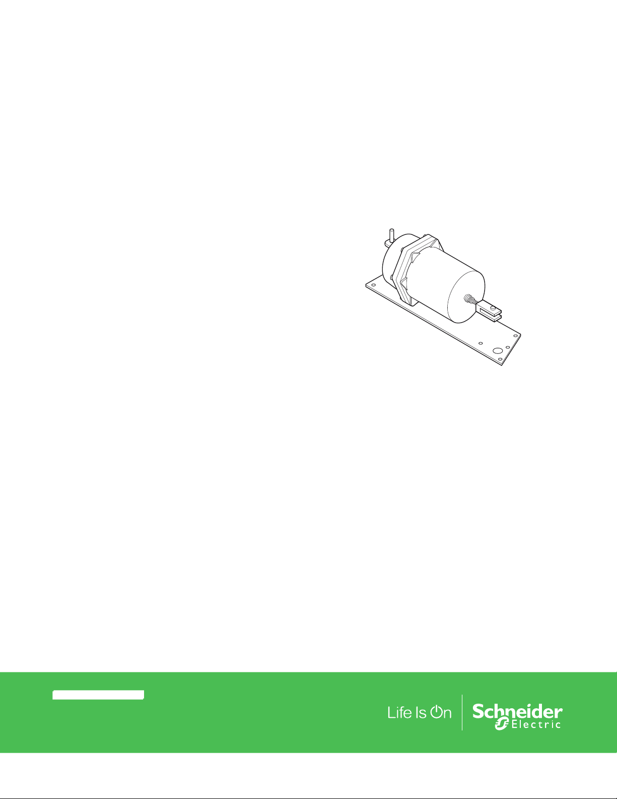
Proportional pneumatic actuator with 20 in. (129 cm)
effective area used to control damper and air valves in
heating, ventilating, and air conditioning systems.
Features
• Rugged cast aluminum body.
• Completely enclosed spring.
• Long lasting rolling diaphragms.
• Heavy duty mounting plate included.
Applicable Literature
• Environmental Controls Cross-Reference Guide,
F-23638
• Environmental Controls Reference Manual,
F-21683
• Pneumatic Products Catalog, F-27383
• AK-42309-500 Positive Positioning Pneumatic Relay,
F-22909
© 2017 Schneider Elec tric. A ll righ ts rese rve d. All tr ademar ks are ow ned by Schneider Elect ric Industri es SAS or its af filiat ed companies. August , 2017 tc
Docume nt Number: F-15221-11

SPECIFICATIONS
Installation Instructions
Construction
Housing: Die cast aluminum.
Diaphragm: Replaceable beaded molded neoprene.
Mounting: Any position.
Dimensions of Actuator: 17-5/8 x 7-3/4 x 7-5/8 in. (448 x 197 x 194 mm).
Mechanical
Stroke: Nominal 4-1/2 in. (114 mm), adjustable 4 to 5 in. (102 to 127 mm). Nominal
Damper Area: Actuator sizing should be done in accordance with damper
manufacturer’s specifications.
Start Point: Adjustable, see Table-1.
Spring: Retracts actuator crank arm on loss of air pressure.
Maximum air pressure: 30 psig (207 kPa).
Environment
Ambient Temperature Limits:
Shipping, -40 to 160°F (-40 to 71°C).
Operating, -20 to 160°F (-29 to 71°C).
Air Connections: 1/8” FNPT.
Air Connections (MK4-7100 Series only): Barbed fittings for 1/4” OD poly tube.
Table-1 Model Chart for Actuators.
Maximum Force
Stroke
TAC
Model No.
Nominal
Operating
Range
Starting
Pressure
Adjustable
Based on
1.5 psi
Pressure to
Actuator
15 psi
Supply
Dual Press.
System
psi psi lb. lb. lb. lb. lb. -in. lb. -in. lb. -in.
MK-7101
MK4-7101
MK-7121
MK4-7121
a
Factory installed positive positioner (AK-42309-500) start point adjustable 1 to 12 psi (7 to 83 kPa) with span adjustable 2 to 13 psi (14 to 90 kPa).
b
Nominal torque for actuators without positioner is based on 1.5 psi (10 kPa) pressure change at the actuator.
c
Force and torques based on factory set stroke and starting pressure.
d
Adjust pressure reducing valve so that listed pressures are available at the actuator.
3 to 8 3 ± 0.5 30 110 140 240 67.5
a
8 to 13 8 ± 0.5 130 10 40 140 22.5
a
c
Power Stroke
15 psi
Supply
Single
ress.
P
d
System
20 psi
Supply
Single or
Dual Press.
System
d
Proportional Control
15 psi
Supply
Dual Press.
System
Nominal Torque
15 psi
Supply
Single
Press.
System
67.5 67.5
90 293
Accessories
AK-42309-500 Positive positioner and linkage (do not use with MK2-71X1; positive
positioner does not meet temperature rating of MK2-71X1)
AM-301 90° angle mounting bracket
AM-530
AM-532 Frame mounting kit
AM-538 Actuator brace kit
AM-542 Rod end connector for 5/16 in. (10 mm) rod
AM-543 Actuator shaft extension
Tool-95 Pneumatic calibration tool kit
a
Crank arm for 1/2 in. diameter damper shaft holes for 4-1/2 in.
stroke
b
d
b
cReturn
20 psi
Supply
Single or
Dual Press.
System
d
a
Required to connect damper actuator to damper shaft.
b
Maximum length of 5/16 in. (10 mm) rod which can be used with AM-542, 15 in. (381 mm).
August , 2017 tc © 2017 Schneider Elec tric. A ll righ ts rese rve d. All tr ademar ks are ow ned by Schneider Elect ric Industri es SAS or its af filiat ed companies.
Document Number: F-15221-11
Installation Instructions
INSTALLATION
Inspection
Requirements
MOUNTING
Preparing Damper for
Frame Mounting of Actuator
Inspect the package for damage. If damaged, notify the appropriate carrier immediately. If
undamaged, open the package and inspect the device for obvious damage. Return
damaged products.
• Piping diagrams
• Training: Installer must be a qualified, experienced technician
• Appropriate accessories
Caution:
• Do not exceed the ratings of the device(s).
• Avoid locations where excessive moisture, corrosive fumes, or vibration is present.
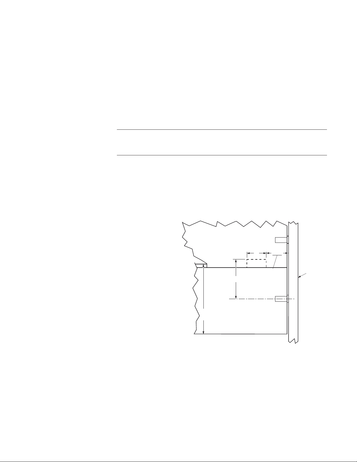
Refer to Figure-16 for mounting hole locations and mounted actuator dimensions. Refer to
Figure-1, Figure-2, and Figure-3 for preparing the damper for a typical bolt on bracket
mounting (AM-532).
2-1/4
Note:
Notched blade next to operating
blade is required for clearance of
clevis and leaf connector.
7" Damper Blade
and Smaller
Operating Blade
2"
Cut This
Portion Out
Taken From Inside Steel
Framing. Dimensions
4"
same for both left and
right hand mounting.
Center Line of
Operating Blade
Figure-1 Bracket Mounting for Dampers with Blades 7” or Smaller.
Damper
Frame
© 2017 Schneider Elec tric. A ll righ ts rese rve d. All tr ademar ks are ow ned by Schneider Elect ric Industri es SAS or its af filiat ed companies. August , 2017 tc
Docume nt Number: F-15221-11
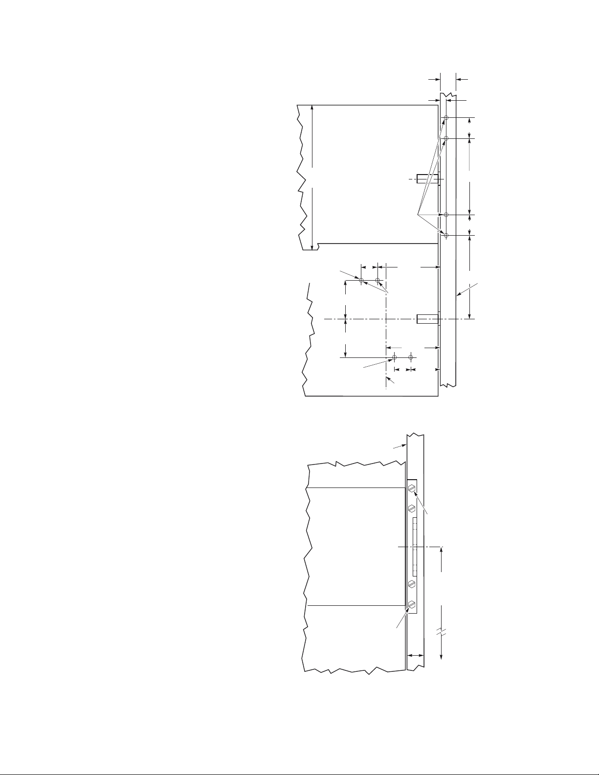
Damper Frame
Width 1" Min.
Operating Blade
Mounting Holes
Closed Damper
Installation Instructions
3/8"
1-1/4"
9" Damper
Blade
Leaf Connector
for Normally
Leaf Connector
Mounting Holes
for Normally
Open Damper
7/32" Dia. Hole for
(4) #14, 3/4" Type
2-5/16"
2-5/16"
"A"
1"
3-3/4"
7/32" Dia.
Hole (2)
3-1/4"
1-3/4"1"
Center Line
of Actuator
4-1/2"
1-1/4"
5"
Damper
Frame
Center Line of
Figure-2 Mounting Dimensions for Bolt-on Bracket, and Leaf Connector.
Damper
Frame
(4) #14, 3/4" Type
"A"
8-1/2" from
Center Line
Damper Blade
Mount bracket Flush to
1/16 from Edge
Minimum Width of Frame
for Bolt-On Bracket 1"
of Operating
Blade
Figure-3 Typical Bolt-on Bracket Mounting.
August , 2017 tc © 2017 Schneider Elec tric. A ll righ ts rese rve d. All tr ademar ks are ow ned by Schneider Elect ric Industri es SAS or its af filiat ed companies.
Document Number: F-15221-11

Installation Instructions
Typical Frame Mountings
Damper Frame Mounting and Linking of Actuator
Requires frame AM-532 (bolt-on). Kit includes the frame bracket, leaf connector, and
necessary screws or bolts and nuts for attaching the kit to the damper. (Refer to Figure-4
through Figure-7 for typical mounting locations.)
Normally Closed
7" Damper Blade
Frame
Bracket
Clevis
Leaf
Connector
Figure-4 Normally Closed 7” Damper Blade.
Frame
Bracket
Clevis
Leaf Connector
Normally Open
7" Damper Blade
Figure-5 Normally Open 7” Damper Blade.
Normally Closed
9" Damper
Frame
Bracket
Clevis
Leaf
Connector
Figure-6 Normally Closed 9” Damper Blade.
Frame
Bracket
Clevis
Leaf Connector
Normally Open
9" Damper
Figure-7 Normally Open 9” Damper Blade.
© 2017 Schneider Elec tric. A ll righ ts rese rve d. All tr ademar ks are ow ned by Schneider Elect ric Industri es SAS or its af filiat ed companies. August , 2017 tc
Docume nt Number: F-15221-11

Installation Instructions
10.Tighten pivot rod nuts to actuator mounting bracket.
1. Drill necessary holes in damper for bolt-on bracket and leaf connector (see Figure-2).
Dampers with blades 7 in. (180 mm) or smaller require notched cut in blade next to
operating blade (see Figure-1).
2. Attach bolt-on (using four #14, 3/4 in. hexhead slotted screws) bracket to damper frame
(see Figure-3).
3. Attach leaf connector using two 1/2 in. sets of nuts and bolts.
4. Remove actuator from its mounting plate.
5. Attach actuator mounting plate to frame bracket (using three 1/2 in. hexhead screws).
6. Reattach actuator to mounting plate.
7. Connect clevis to leaf connector. Clevis can be adjusted in order to align holes in clevis
and leaf connector.
Actuator Mounting Brace Kit AM-538
To ensure smooth (non-jerky) operation of a damper (or other final control element), to
prevent unnecessary cycling, and to prevent any type of binding actuator operation action
(which may damage the actuator), the mounting means of each actuator must be rigidly
secured to prevent any flexing movement as the actuator drives the final control element
(damper, butterfly valve, etc.) through its full range of movement. It is sometimes necessary
to devise special means to support the actuator rigidly. In many cases, the AM-538 brace kit
can be used for this purpose (refer to Figure-8).
In cases where the AM-538 kit cannot be used, other mean
the actuator rigidly. For actuators mounted on a pivot rod (for example, a “post-mounted”
actuator), the driven shaft of the final control element and the pivot rod must be kept parallel
to each other to prevent binding. In some cases, an outboard bearing mounted near the
crank-arm must be used to keep the driven shaft from flexing.
s should be devised to support
Pivot
Rod
Leaf
Connector
Threaded
Rod
Rod End
Connector
Figure-8 MK-7000 Series with Brace Kit.
1. Cut threaded rod to desired length.
2. Thread pivot rod end fitting to threaded rod.
3. Loosely assemble leaf connector to threaded rod end fitting.
4. Thread one nut to approximately 7 in. (180 mm) on the other end of threaded rod.
5. Slide threaded rod from damper side through pivot rod hole (pivot rod must be loosened
from actuator bracket).
6. Locate leaf connector on edge of damper frame and mark position to drill mounting holes.
7. Drill two mounting holes 7/32 in. (6 mm) dia.
8. Mount leaf connector to damper frame.
9. Tighten nuts on threaded rod to actuator pivot rod.
August , 2017 tc © 2017 Schneider Elec tric. A ll righ ts rese rve d. All tr ademar ks are ow ned by Schneider Elect ric Industri es SAS or its af filiat ed companies.
Document Number: F-15221-11
Installation Instructions
External
7/8
Clevis Pin Hole
Set Screws
3-59/64
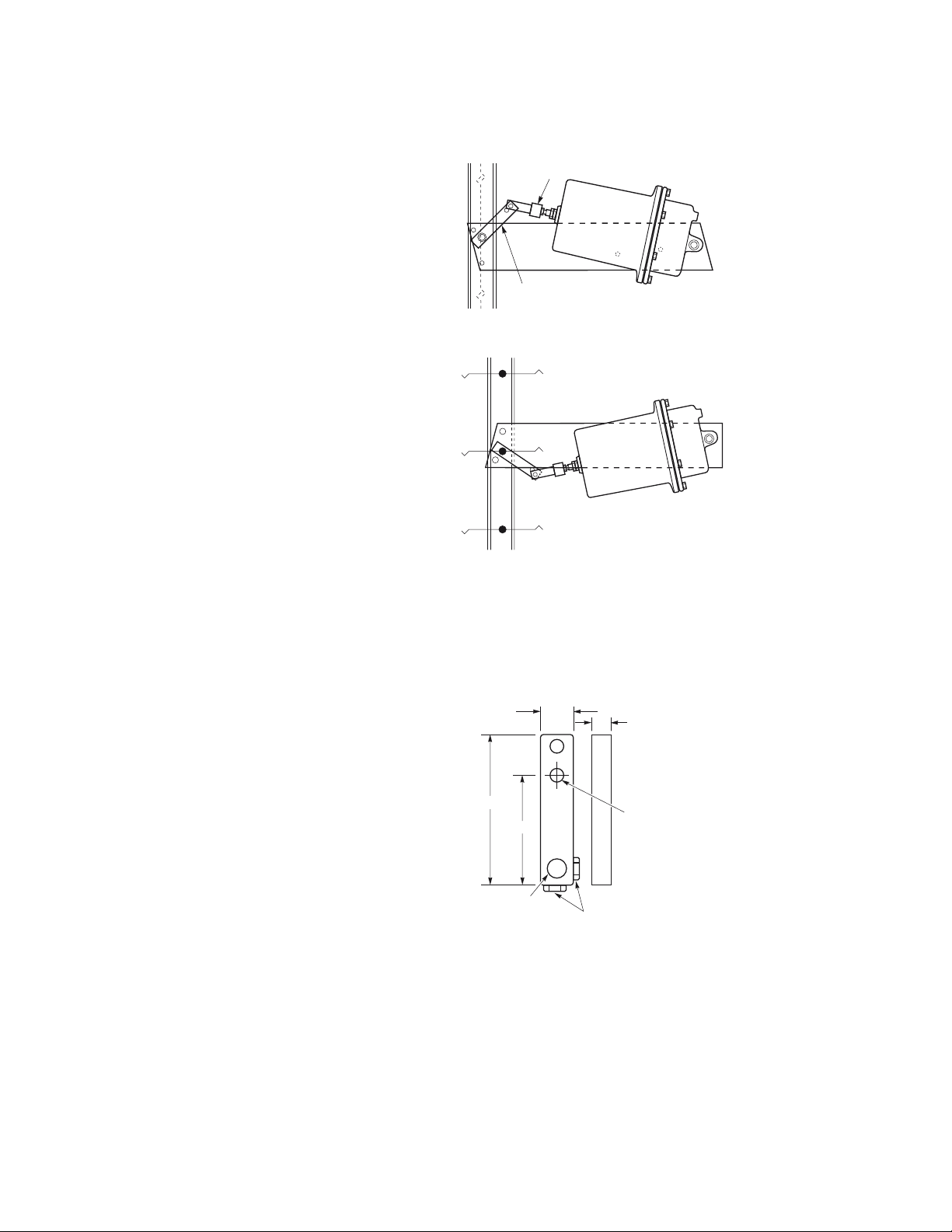
External Mounting and Linking of Actuator Using AM-530 Crank Arm
Refer to Figure-9 and Figure-10.
Clevis
Crank Arm (AM-
Mounted
Figure-9 External Mounted Normally Closed.
External
Mounted
Figure-10 External Mounted Normally Open.
1. Remove actuator from its mounting plate.
2. Attach mounting plate to duct or wall with damper shaft protruding through location hole
in mounting plate.
3. Attach actuator to mounting plate.
4. Loosely install crank arm (AM-530) to damper shaft at approximately 45° angle from
perpendicular toward actuator.
1/2
2-15/32
33/64 Dia.
25/64 Dia.
5/16-24
Figure-11 AM-530 Crank Arm.
5. Manually position damper to full retracted actua
tor position. Tighten crank arm in position
described in Step 4.
6. Connect clevis to crank arm in farthest hole from damper shaft. Adjust clevis if necessary.
Connection of Air Line
Control air lines must be terminated at the actuator with at least 6 in. (150 mm) of flexible
tubing allowing for pivoting of the actuator.
© 2017 Schneider Elec tric. A ll righ ts rese rve d. All tr ademar ks are ow ned by Schneider Elect ric Industri es SAS or its af filiat ed companies. August , 2017 tc
Docume nt Number: F-15221-11

Floor Mounting and Linking of Actuator
Refer to Figure-12.
Damper Blade
Shaft
Crank
Arm
Clevis
Installation Instructions
AM-301 Mounting
Floor
Bracket (Bolt to
floor)
Figure-12 Typical Floor Mounting.
Requires AM-530 crank arm and AM-301 90° bracket.
1. Assemble crank arm to damper shaft extension.
2. Assemble actuator pivot rod 90° mounting bracket.
3. Position actuator and attach bracket to floor.
4. Link actuator to damper shaft.
AM-301 Mounting
Actuator Pivot
Bracket (Bolt to
Rod
floor)
August , 2017 tc © 2017 Schneider Elec tric. A ll righ ts rese rve d. All tr ademar ks are ow ned by Schneider Elect ric Industri es SAS or its af filiat ed companies.
Document Number: F-15221-11

Installation Instructions
1/8 MNPT x 1/4"
1/4 OD
Plastic Tub
(Field
Output to
Units with Factory
Mounted Positive
Positioners
Install fittings required in Ports P and M on positive positioner.
Adjustments
Refer to Figure-13.
Span Adjustment
The span is adjustable from 2 to 13 psig (14 to 90 kPa).
1. Insert the feedback spring into the adjustment slider.
2. Adjust the slider so that the spring is aligned with the required line on the scale.
Note: Span is the change of input pressure required to produce a full actuator stroke.
3. The scale is dimensional for a 4 in. (102 mm) actuator stroke. If the stroke length is other
than 4in. (102 mm), calculate the adjustment slider position as follows:
Adjustment Scale Position =
Required Input Span x 4
Required Actuator Stroke Length
Start Point
The start point is adjustable from 1 to 12 psi (7 to 83 kPa). Start point is the pressure at which
the actuator just begins to extend. See Figure-13 below.
Barb Elbow
(Field Supplied)
Actuator Top
1st Stop Nut
Cover
Screw
Span Slider Screw
(through slot)
Feedback Spring
AK-42309-500
Positioner
Start Pont Lock Screw
Clevis
Clevis
Lock Nut
Feedback
Arm
Figure-13 MK-7000 Series Actuator with AK-42309-500 Positioner.
1. Connect main air supply to Port M and a variable air supply to Port P.
2. Adjust variable air supply on Port P to desired start point pressure.
3. Loosen the start point lock screw with a small screwdriver.
4. Adjust the start point lever until the actuator just starts to extend.
5. Tighten the start point lock screw.
6. Remove variable air supply from Port P.
7. Connect Port P to controller output.
B
Pilot From Controller
P
M
Main Air
Figure-14 Typical Piping Diagram with Factory Mounted Positive Positioner.
© 2017 Schneider Elec tric. A ll righ ts rese rve d. All tr ademar ks are ow ned by Schneider Elect ric Industri es SAS or its af filiat ed companies. August , 2017 tc
Docume nt Number: F-15221-11

Note: If slave damper actuators are to be controlled, tee into the tubing from Port B to the
actuators. All dampers must be mechanically interconnected.
Field Mounting of Actuator
with Positive Positioner
Field mounting of actuator with positive positioner is the same as for a factory mounted
positive positioner. Refer to AK-42309-500, Positive Positioning Pneumatic Relay
General Instructions, F-22909, for additional information.
CHECKOUT
After installation, the actuator should be checked to ensure proper damper operation. To
check the actuator and linkage, proceed as follows:
1. Check the linkage with the actuator in the retracted position for proper return force. The
2. Apply air pressure to the actuator or pilot port of a positioner and check the linkage as
3. The above can be obtained through adjustment of the clevis or by adjustment of the
Installation Instructions
actuator should be linked so that on a normally closed application, the damper is closed
with no more than 1/16 in. (2 mm) compression of the spring. (The actuator shaft would
return an additional 1/16 in. (2 mm) if the linkage were disconnected.) For a normally open
application, the actuator should be linked with the actuator fully retracted.
follows. On a normally closed application, the damper should be just full open when the
actuator piston reaches the stop nuts in the actuator. On a normally open application, the
damper should reach the closed position with no more than 1/16 in. (2 mm) stroke
remaining to reach the actuator stop nuts.
actuator stop nuts.
Adjustable Starting Pressure
Actuators are available with adjustable starting pressure. To adjust the starting pressure,
turn stop nut on the actuator shaft clockwise to increase and counterclockwise to decrease
the starting pressure. Each rotation of the stop nut changes the starting pressure 0.04 psi
(0.28 kPa). See Figure-16.
Adjustable Stroke Length
Stroke length is determined by the two stop nuts on the actuator shaft. See Figure-16. Stops
are set for 4-1/2 in. (114 mm) stroke. Turning stop nuts clockwise will shorten stroke length.
Turning stop nuts counterclockwise will lengthen the stroke. Maximum stroke length is 5 in.
(127 mm). By increasing the stroke length, the force available to resist an opposing force is
decreased while decreasing the stroke length increases this force.
August , 2017 tc © 2017 Schneider Elec tric. A ll righ ts rese rve d. All tr ademar ks are ow ned by Schneider Elect ric Industri es SAS or its af filiat ed companies.
Document Number: F-15221-11

Installation Instructions
8-11/16"
Stop Nuts
(Optional)
7-3/4"
Stop Nuts
17-5/8"
MAINTENANCE
Diaphragm Replacement
Regular maintenance of the total system is recommended to assure optimum performance.
See Figure-15.
Top Power Housing
Housing
Screws
Stop
Nuts
Figure-15 MK-7000 Series Housing Item Identification.
DIMENSIONAL DATA
7-5/8"
Caution:
Make certain the stop nuts are in place on the actuator shaft, otherwise the cup and shaft
assembly, as well as the spring, may be released from the actuator.
1. Remove the six screws holding the top power housing.
2. Remove the top power housing and old diaphragm.
3. Roll the new diaphragm (PND-202) inside out and install over the piston. Make sure the
circular bead is facing up.
4. Reinstall the top power housing making sure the bead on the diaphragm is in the housing
groove and the screw holes are lined up.
5. Install and tighten housing screws.
AM-530
1/8"
17-7/16"
20-3/16"
15-5/8"
Figure-16 MK-7000 Series Actuator and Mounting Plate Dimensions.
2-1/2"
© 2017 Schneider Elec tric. A ll righ ts rese rve d. All tr ademar ks are ow ned by Schneider Elect ric Industri es SAS or its af filiat ed companies. August , 2017 tc
Docume nt Number: F-15221-11

Dimensions
5/16-18 Tap for Fastening Plate
to AM-532
3/4" Dia. for locating Plate when Duct Mounting.
This Hole for N.C.
5/8" dia.
Installation Instructions
Dampering Shaft protrudes thru Hole.
3-1/2
1-5/16
5-3/16
9/32" Dia. Holes for Mounting
to Duct or Wall (5)
Note:
The AM-538 kit includes leaf
connector,and the required
nuts, bolts, and screws.
The AM-542 kit includes the
rod end connector.
Frame Mounting.
This Hole for N.O.
Frame Mounting.
12-5/16
20-3/16
19-1/2
Actuator Mounting
Figure-17 MK-7000 Series Mounting Plate.
5/16-24 Threaded
Set Screw
For 5/16" dia. Rod
7/16-14 Thread for
Actuator Shaft
This Hole for Duct
or Wall Mounting.
3-5/8
1/4
36"
2 Nuts
Leaf
Figure-18 AM-538 and AM-542 Kits.
4-3/4"
Figure-19 AM-543 Actuator Shaft Extension.
August , 2017 t © 2017 Schneider Elec tric. A ll righ ts rese rve d. All tr ademar ks are ow ned by Schneider Elect ric Industri es SAS or its af filiat ed companies.
Document Number: F-15221-11
 Loading...