

Page 1
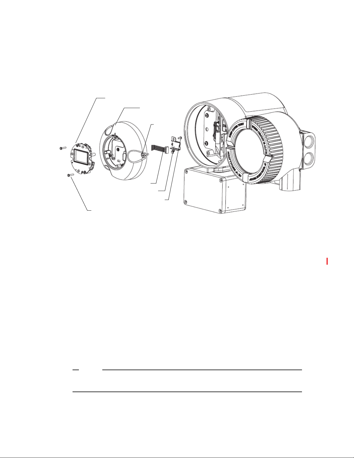
Instruction MI 019-140
November 2019
Digital Coriolis Mass Flow Transmitter Model CFT51
with HART
Installation, Startup, Configuration, and Maintenance
®
or Modbus® Communication Protocol
Page 2

MI 019-140 – November 2019
2
Page 3

Contents
Figures...........................................................................................................................................9
Tables ..........................................................................................................................................11
Important Information................................................................................................................13
Please Note ...............................................................................................................................13
1. Introduction ............................................................................................................................ 15
Overview...................................................................................................................................15
Reference Documents ...............................................................................................................15
Transmitter Identification..........................................................................................................16
Standard Specifications..............................................................................................................17
Modbus Specifications...............................................................................................................18
Electromagnetic Compatibility (EMC) Specifications ...............................................................18
Electrical Safety Specifications...................................................................................................19
Electrical Safety Warnings.....................................................................................................21
For Explosionproof Certifications.........................................................................................21
2. Installation ..............................................................................................................................23
Mounting..................................................................................................................................23
Positioning the Housing............................................................................................................24
Rotating the Display.............................................................................................................27
Cover Lock Versions..................................................................................................................28
Locking Pins.........................................................................................................................29
Wire Seals.............................................................................................................................30
Wiring ......................................................................................................................................37
Field Wiring.........................................................................................................................38
Transmitter Power Wiring ....................................................................................................41
Transmitter ac Power Supply............................................................................................42
Transmitter dc Power Supply ...........................................................................................43
Input/Output Wiring...........................................................................................................44
Modbus Wiring...............................................................................................................45
Current Output MA1 and HART Communication Interface ..........................................46
Current Outputs MA2 and MA3.....................................................................................46
Contact Input (DIN).......................................................................................................47
Contact Output (DOUT) ...............................................................................................47
Pulse Outputs 1 and 2 .....................................................................................................48
3
Page 4

MI 019-140 – November 2019 Contents
HART Digital Multidrop Communication ..........................................................................50
Transmitter Wiring Connections from Flowtube..................................................................51
Write Protect Jumper............................................................................................................52
3. Quick Start.............................................................................................................................. 55
When to Use Quick Start Mode................................................................................................55
Steps Required ..........................................................................................................................56
Procedure Using Keypad/Display ..............................................................................................57
Procedure Using the HART Communicator .............................................................................60
4. Using the Local Display........................................................................................................... 61
Using the Local Display ............................................................................................................61
Top Level Menu ........................................................................................................................62
Measure Mode ..........................................................................................................................63
Configuring Totals ....................................................................................................................64
Quick Start Mode .....................................................................................................................66
Status Mode..............................................................................................................................66
Alarm Actions ...........................................................................................................................68
Conditions That Can Be Alarmed........................................................................................68
Actions of Transmitter During Alarm Conditions.................................................................68
Diagnostic Actions ....................................................................................................................69
Conditions That Can Be Diagnosed .....................................................................................69
Actions of Transmitter During Diagnostic Conditions..........................................................69
View Mode ...............................................................................................................................70
Setup Mode...............................................................................................................................71
5. Operation with HART Protocol.............................................................................................. 73
Using the HART Communicator..............................................................................................73
Connecting the HART Communicator................................................................................73
Overview of Top Level Menus...................................................................................................74
Communicator Keyboard and Display ......................................................................................74
Offline Configuration ...............................................................................................................74
Online Operation......................................................................................................................74
mA Calibration Procedure Using the HART Communication Protocol ....................................75
Online Flowchart .................................................................................................................76
Explanation of Online Parameters ........................................................................................77
6. Operation with Modbus Protocol............................................................................................ 79
Modbus Communication Overview..........................................................................................79
Modbus Protocols ................................................................................................................79
4
Page 5

Contents MI 019-140 – November 2019
Modbus Function Codes......................................................................................................80
Modbus Commands........................................................................................................80
Diagnostic Command Options Supported.......................................................................80
Modbus Communication Configurations........................................................................81
Controlling Access to the Configuration Database ...............................................................82
Hardware Write Protect...................................................................................................82
Software Passwords ..........................................................................................................82
Mechanical Protection .....................................................................................................82
Modbus Registers......................................................................................................................83
Access Information...............................................................................................................83
Access Status (303581) ....................................................................................................83
Password Entry (404176-404178) ...................................................................................83
Dynamic Measurements.......................................................................................................84
Standard Measurement ....................................................................................................84
Uncorrected Measurement Values ....................................................................................84
Component Flow Rate Values..........................................................................................84
Totalizer Value.................................................................................................................85
Measurement EGU Labels...............................................................................................85
Status Information................................................................................................................86
Tube Status......................................................................................................................86
Transmitter Status............................................................................................................87
Tube Settings ...................................................................................................................88
Measurement Status.........................................................................................................88
Alarm Status....................................................................................................................89
Diagnostic Status.............................................................................................................90
Status Counters ...............................................................................................................91
Tags......................................................................................................................................92
Configuration Parameters.....................................................................................................92
Measurement Parameters .................................................................................................93
Totalizers .........................................................................................................................99
Output Parameters ........................................................................................................102
Display Parameters ........................................................................................................113
Component Measurements............................................................................................116
Process Limits................................................................................................................117
Alarm Parameters...........................................................................................................118
System Parameters .........................................................................................................122
Modbus Communication Parameters.............................................................................124
Calibration .........................................................................................................................125
mA Output Calibration.................................................................................................125
mA Calibration Procedure Using Modbus Protocol............................................................127
Density Calibration .......................................................................................................127
Flow Zero......................................................................................................................128
5
Page 6

MI 019-140 – November 2019 Contents
Meter Verification..........................................................................................................130
Pressure Compensation..................................................................................................131
Test Functions ....................................................................................................................132
System Information............................................................................................................133
Modbus Register Database ......................................................................................................133
7. Setup..................................................................................................................................... 151
When to Use Setup Modes......................................................................................................151
Steps Required ........................................................................................................................151
Configurable Parameters .........................................................................................................152
Setting Measure Parameters ................................................................................................162
Mass Flow .....................................................................................................................162
Volume Flow .................................................................................................................163
Density..........................................................................................................................164
Concentration ...............................................................................................................165
Temperature ..................................................................................................................169
Totals.............................................................................................................................169
Component A and B Mass Measurements .....................................................................171
Component A and B Volume Measurements .................................................................171
Setting Output Parameters .................................................................................................171
Milliampere Output ......................................................................................................171
Pulse Output .................................................................................................................172
Contact Output (DOUT) .............................................................................................174
Contact Input (DIN).....................................................................................................174
Display ..........................................................................................................................175
Setting HART-Specific Output Parameters....................................................................175
Setting View Parameters .....................................................................................................175
Location ........................................................................................................................175
Tube Model Code..........................................................................................................176
Tube Serial Number.......................................................................................................176
Setting HART-Specific Output Parameters....................................................................176
Setting Test Parameters.......................................................................................................176
Setting Calibration Parameters ...........................................................................................176
Model (Flowtube)..........................................................................................................177
Flow Constants..............................................................................................................177
Density Constants .........................................................................................................177
K-Bias............................................................................................................................178
Density Calibration .......................................................................................................178
Flow Direction ..............................................................................................................180
Zeroing the Transmitter .................................................................................................180
Meter Verification Function...........................................................................................181
6
Page 7

Contents MI 019-140 – November 2019
Low Flow Cut-Off.........................................................................................................182
Density Limit ................................................................................................................182
Fluid..............................................................................................................................182
2 Phase ..........................................................................................................................183
Pressure Compensation..................................................................................................184
Milliampere Calibration ................................................................................................186
Calibration Identification ..............................................................................................186
Setting System Parameters ..................................................................................................186
Password........................................................................................................................186
Alarm Acknowledge.......................................................................................................187
Diagnostic Acknowledge................................................................................................187
Set Factory Configuration..............................................................................................187
Set Communication Protocol ........................................................................................187
HART-Specific System Parameters.................................................................................187
Modbus-Specific System Parameters ..............................................................................188
Modbus Configuration..................................................................................................189
Setting Alarm Parameters ...................................................................................................189
Using the HART Communicator ............................................................................................190
Explanation of Setup Parameters ...................................................................................192
8. Troubleshooting ....................................................................................................................195
Error Codes.............................................................................................................................195
Fault Location.........................................................................................................................196
Setup Issues.............................................................................................................................199
Measurement Issues.................................................................................................................200
9. Maintenance.......................................................................................................................... 201
Preparing for Installation.........................................................................................................201
Reference Documents.........................................................................................................201
Required Tools ...................................................................................................................202
Installation Requirements........................................................................................................202
Installation Considerations......................................................................................................202
Replacing the Electronics Module ...........................................................................................203
Returning the Transmitter to Service .......................................................................................209
10. Model Code......................................................................................................................... 211
11. Dimensions .........................................................................................................................213
Digital Coriolis Mass Flow Transmitter Models CFT51 ..........................................................213
12. Parts List .............................................................................................................................217
7
Page 8

MI 019-140 – November 2019 Contents
Parts........................................................................................................................................217
Recommended Spare Parts ......................................................................................................224
Appendix A. Custom Slopes ...................................................................................................... 225
Mass Flow...............................................................................................................................225
Volume Flow...........................................................................................................................225
Density ...................................................................................................................................225
Totals ......................................................................................................................................225
Appendix B. Setup Diagrams..................................................................................................... 227
Setup Menu Structure Using HART Communication Protocol...............................................228
Setup Menu Structure Using Modbus Communication Protocol ............................................238
8
Page 9

Figures
1 Transmitter Identification....................................................................................................16
2 Transmitter Mounting.........................................................................................................23
3 Wall Mounting....................................................................................................................24
4 Vertical Pipe Mounting - Orientation 1...............................................................................24
5 Vertical Pipe Mounting - Orientation 2...............................................................................25
6 Vertical Pipe Mounting - Orientation 3...............................................................................25
7 Horizontal Pipe Mounting ..................................................................................................26
8 Display Orientation ............................................................................................................27
9 Cover Locking Pins for All Model Code Selections .............................................................29
10 Cover Locks for Tamperproof Sealing (-S), U.S. Weights and Measures Custody Transfer
NTEP (-T), and Weights and Measures Industry Canada Approvals (-D) Model Code
Selections ......................................................................................................................30
11 Aligning Cover Lock Screws with Housing..........................................................................31
12 Inserting the Wire in the Holes in the Housing ...................................................................32
13 Pulling the Wire Through the Housing...............................................................................32
14 Pulling the Wire Through the Housing Screws....................................................................33
15 Inserting Both Ends of the Wire Through the Seal ..............................................................34
16 Positioning the Seal and Crimping the Wire........................................................................34
17 Transmitter Junction Block - Cover Locks...........................................................................35
18 Flowtube Junction Box........................................................................................................36
19 Overview of Transmitter Wiring with a CFS10 or CFS20 Flowtube ...................................37
20 Accessing Field Terminals ....................................................................................................39
21 Field Wiring Terminal Board...............................................................................................40
22 Transmitter Power Wiring ...................................................................................................41
23 Transmitter ac Power Connection Terminals .......................................................................42
24 Transmitter dc Power Connection Terminals .......................................................................43
25 Typical Modbus Wiring ......................................................................................................45
26 Typical HART Wiring (Current Output MA1)...................................................................46
27 Current Output Wiring (MA2 and MA3)...........................................................................46
28 Contact Input Wiring (DIN) ..............................................................................................47
29 Contact Output Wiring (DOUT).......................................................................................47
30 Pulse Output with a Sourcing Input Receiver (with Internal Current Limiting,
Pulse Output 1 or Pulse Output 2) ...............................................................................48
31 Pulse Output with a Sourcing Input Receiver (without Internal Current Limiting,
Pulse Output 1 or Pulse Output 2) ...............................................................................48
32 Pulse Output with a Receiver Requiring a Sinking Input (Pulse Output 1 or
Pulse Output 2) ............................................................................................................49
33 Pulse Output with a Sinking Input Receiver Using a Divider Network (Pulse Output 1 or
Pulse Output 2) ............................................................................................................49
34 Typical HART Multidrop Network.....................................................................................50
35 Transmitter Junction Box ....................................................................................................51
36 Write Protect Jumper Location............................................................................................52
37 Write Protect Jumper Position.............................................................................................53
9
Page 10

MI 019-140 – November 2019 Figures
38 Keypad/Display Quick Start Menu ....................................................................................57
39 HART Communicator Quick Start Menu ..........................................................................60
40 Local Display ......................................................................................................................61
41 Top Level Modes and Their Basic Functions .......................................................................62
42 Measure Mode Structure Diagram.......................................................................................65
43 Status Mode Structure Diagram ..........................................................................................67
44 View Mode Structure Diagram - HART Communication Protocol.....................................70
45 View Mode Structure Diagram - Modbus Protocol .............................................................71
46 Connection of HART Communicator (MA1 Only)............................................................73
47 CFT51 Transmitter Top Level Online Menu.......................................................................74
48 HART Online Flowchart ....................................................................................................76
49 Density Constants Flowchart ............................................................................................179
50 Setup Flowchart ................................................................................................................191
51 Removing the Front Windowed Cover..............................................................................204
52 Loosening the Display Bezel Screws ..................................................................................205
53 Disconnecting the Display Ribbon Cable..........................................................................205
54 Disconnecting the Wire Harness Plugs ..............................................................................206
55 Loosening the Electronics Module Screws.........................................................................206
56 Removing the Electronics Module.....................................................................................207
57 Determining the Location of the Adhesive Sink Pad..........................................................208
58 Lining Up the Electronic Module Pegs with the Holes in the Case....................................208
59 CFT51 (Frontal View) ......................................................................................................213
60 CFT51 (Side View) ...........................................................................................................214
61 CFT51 (Bottom View)......................................................................................................215
62 Mounting Bracket (Side View and Bottom View)..............................................................216
63 Parts for Housing, Display, and Cover Locks.....................................................................217
64 Parts Breakdown for Electronics ........................................................................................219
65 Parts Breakdown for Mounting Kit ...................................................................................220
66 Level 2 Setup Menu Structure (HART).............................................................................228
67 Level 3 Setup Measure Structure (HART).........................................................................229
68 Level 3 Setup Measure Structure (HART) (Continued).....................................................230
69 Level 3 Setup Measure Structure (HART) (Continued).....................................................231
70 Level 3 Setup Output Structure (HART) ..........................................................................232
71 Level 3 Setup Output Structure (HART) (Continued)......................................................233
72 Level 3 View and Test Structure (HART)..........................................................................234
73 Level 3 Calibration Structure (HART) ..............................................................................235
74 Level 3 Calibration Structure (HART) (Continued)..........................................................236
75 Level 3 System Structure (HART) .....................................................................................237
76 Level 2 Setup Menu Structure (Modbus)...........................................................................238
77 Level 3 Setup Measure Structure (Modbus).......................................................................239
78 Level 3 Setup Measure Structure (Modbus) (Continued)...................................................240
79 Level 3 Setup Measure Structure (Modbus) (Continued)...................................................241
80 Level 3 Setup Output Structure (Modbus) ........................................................................242
81 Level 3 Setup Output Structure (Modbus) (Continued)....................................................243
82 Level 3 View and Test Structure (Modbus)........................................................................244
83 Level 3 Calibration Structure (Modbus) ............................................................................245
84 Level 3 Calibration Structure (Modbus) (Continued)........................................................246
85 Level 3 System Structure (Modbus) ...................................................................................247
10
Page 11

Tables
1 Reference Documents .........................................................................................................15
2 Standard Specifications........................................................................................................17
3 Modbus Specifications.........................................................................................................18
4 International and European Union Standards......................................................................18
5 Power (Limits): 102 to 264 Vac; 47 to 63 Hz .....................................................................42
6 dc Power: 10-36 Vdc...........................................................................................................43
7 I/O Wiring..........................................................................................................................44
8 Transmitter Junction Box Wiring ........................................................................................51
9 Operation of Function Keys................................................................................................58
10 Operation of Function Keys................................................................................................61
11 Modbus Registers..............................................................................................................134
12 Configurable Parameters ...................................................................................................152
13 Alphanumeric Characters ..................................................................................................162
14 Concentration Limits ........................................................................................................165
15 Pressure Effects on Flowtubes............................................................................................185
16 Error Codes.......................................................................................................................195
17 Parameter Number Error Codes ........................................................................................195
18 No/Incorrect Flow Measurement.......................................................................................196
19 Milliampere and Frequency Output Problems...................................................................198
20 HART Communication Problems.....................................................................................198
21 Display Problems ..............................................................................................................199
22 Setup Issues.......................................................................................................................199
23 Concentration Measurement Problems..............................................................................200
24 Replacement Kits for CFT51 Electronics Module.............................................................201
25 Parts List for Figure 63, Figure 64, and Figure 65..............................................................220
26 Electronics Module Assembly Kit......................................................................................222
27 Additional Cable to Flowtube ...........................................................................................223
28 Mass Flow Custom Slope ..................................................................................................225
29 Volume Flow Custom Slope ..............................................................................................225
30 Density Custom Slope.......................................................................................................225
31 Totals Custom Slope .........................................................................................................225
11
Page 12

MI 019-140 – November 2019 Tab l e s
12
Page 13
Important Information
!!!
Read these instructions carefully and look at the equipment to become familiar with the device
before trying to install, operate, service, or maintain it. The following special messages may
appear throughout this manual or on the equipment to warn of potential hazards or to call
attention to information that clarifies or simplifies a procedure.
The addition of either symbol to a “Danger” or “Warning” safety label
indicates that an electrical hazard exists which will result in personal injury
if the instructions are not followed.
This is the safety alert symbol. It is used to alert you to potential personal injury
hazards. Obey all safety messages that follow this symbol to avoid possible injury or
death.
DANGER
DANGER indicates a hazardous situation which, if not avoided, will result in death or serious
injury.
WAR NIN G indicates a hazardous situation which, if not avoided, could result in death or
serious injury.
CAUTION indicates a hazardous situation which, if not avoided, could result in minor or
moderate injury.
NOTICE is used to address practices not related to physical injury.
Please Note
Electrical equipment should be installed, operated, and maintained only by qualified personnel.
No responsibility is assumed by Schneider Electric for any consequences arising out of the use of
this material.
A qualified person is one who has skills and knowledge related to the construction, installation,
and operation of electrical equipment and has received safety training to recognize and avoid the
hazards involved.
WARNING
CAUTION
NOTICE
13
Page 14

MI 019-140 – November 2019 Important Information
14
Page 15

1. Introduction
Overview
The CFT51 Digital Coriolis Mass Flow Transmitter, when used with a Foxboro® CFS flowtube,
measures the mass flow rate, density, and temperature of process fluid directly. It uses digital signal
processing technology in conjunction with the Coriolis principle. The transmitter provides
frequency, scaled pulse, 4 to 20 mA current, alarm, and contact outputs. It also supports
nonvolatile totalization of the output.
You can configure the CFT51 transmitter to use the HART or Modbus communication protocol
via LCD indicator pushbuttons on the transmitter at any time.
HART communications protocol can be used in full digital communications mode to a HART
host system, or as a direct analog communications interface over the 4-20 mA analog signal with a
HART communicator or the configuration software.
Modbus communications protocol allows full digital communications using a Modbus
communication interface.
Local communication is always available using the LCD indicator/configurator.
Reference Documents
In addition to this instruction, there is other user documentation supporting the CFT51
Transmitter, as listed in Table 1.
Table 1. Reference Documents
Document
Number Document Description
DP 019-182 Dimensional Print – CFS10 Style B Flowtubes (1/4 through 2 inch)
DP 019-183 Dimensional Print – CFS20 Style B Flowtubes (11/2 and 3 inch)
DP 019-366 Dimensional Print – CFS10 Style B Flowtubes (1/8 inch)
DP 019-376 Dimensional Print – CFT51 Transmitter
MI 019-120 Instruction – CFS10 and CFS20 Mass Flowtubes
MI 019-141 Instruction – CFT51 Safety Connection Diagrams (FM, CSA)
MI 019-179 Flow Products Safety Information
MI 019-276 Advanced DTM Library – Operation Using Modbus Communication Protocol
MI 020-520 Field Device Tool with Advanced DTM Library – Operation Using HART Communication Protocol
PL 008-752 Parts List – CFT51 Transmitter
PL 008-733 Parts List – CFS10 Style B Flowtubes
PL 008-735 Parts List – CFS20 Style B Flowtubes
15
Page 16
MI 019-140 – November 2019 1. Introduction
MODEL NO .
ORIGIN
S/N
INPUT SUPPLY
INPUT POWER
AMBIENT TEMP.
ST.
CUST. DAT
A
60 Cº
CABLE ENTRIES
MASS FLOWMETER
R
- 40 ºC TO
SCHNEIDER ELECTRIC SYSTEMS USA, INC.
38 NEPONSET AVE.
FOXBORO, MA 02035
SEE SALES ORDER
STYLE “A”
DESIGNATION
SERIAL NUMBER
MODEL CODE
PER SALES ORDER
DATE CODE
120/240 V ac 50/60 Hz
or 36 V dc MAX
20 VA MAX or 1A, 15 W
TYPE OF CONDUIT OPENINGS
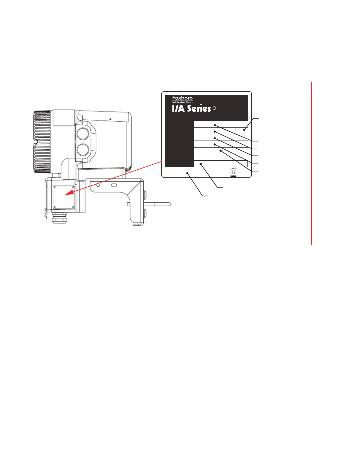
Transmitter Identification
A data plate fastened to the side of the housing provides the model number and other information
as described in Figure 1. Some of this information is also available in the configuration software of
the transmitter.
Figure 1. Transmitter Identification
16
Page 17

1. Introduction MI 019-140 – November 2019
Standard Specifications
Table 2. Standard Specifications
Item Specification
Ambient Temperature
Normal Operating Condition Limits –40 and +60°C (–40 and +140°F) (a)
Relative Humidity Limits 5 and 100% (with transmitter covers installed)
Power Supply (ac) Nominal: 120/240 Vac 50/60 Hz, 20 VA Maximum
Power Supply (dc) 10 - 36 Vdc
Current Output Limits
Supply Voltage
Load
Current
Pulse Output Limits
Supply Voltage
Current
Contact Input
Supply Voltage
Current
Contact Output Limits
Supply Voltage
Current
Vibration Limits 5 m/s
a. At temperatures between -40 and -20° C, the display may fade or appear to be blank; however, the device is still operational.
b. For installations that require safety certifications, the maximum input voltage is 250 Vac.
Limits: 102 to 264 Vac; 47 to 63 Hz (b)
10 W typical; 15 W maximum
3 A startup current
24 Vdc ±10% (External Power Supply)
0 to 683 (250 to 683 with Current Output 1 when HART Communicator
or PC-Based Configurator is used)
22 mA maximum, 3.8 mA minimum
24 Vdc ±10% (External Power Supply)
80 mA maximum
24 Vdc ±10% (External Power Supply)
15 mA minimum
24 Vdc ±10% (External Power Supply)
100 mA maximum
2
(0.5 “g”) from 5 to 500 Hz
17
Page 18

MI 019-140 – November 2019 1. Introduction
Modbus Specifications
Table 3. Modbus Specifications
Item Possible Configurations As Shipped Configuration
Baud Rate 1200, 2400, 4800, 9600, 19200, 38400 9600
Format None, Odd, Even None
Device Address 1 through 247 247
Byte Order 0123, 2301, 1032, 3210 2301
Electromagnetic Compatibility (EMC) Specifications
The CFT51 Transmitter complies with international and European Union standards listed in
Ta bl e 4 .
Table 4. International and European Union Standards
Parameter IEC Standard EN Standard
Radiated RFI Immunity 10 V per IEC 61000-4-3 10 V per EN 61000-4-3
Conducted RFI Immunity 10 V per IEC 61000-4-6 10 V per EN 61000-4-6
RFI Radiated and Conducted Emissions CISPR Class A EN 55011 Class A
ESD Immunity 6 kV contact discharge per
IEC 61000-4-2
Electrical Fast Transients/Burst Immunity Power 2 kV per IEC 61000-4-4 2 kV per EN 61000-4-4
Electrical Fast Transients/Burst Immunity I/Os 1 kV per IEC 61000-4-4 1 kV per EN 61000-4-4
Surge Immunity Power 2 kV per IEC 61000-4-5 2 kV per IEC 61000-4-5
Surge Immunity I/Os 1 kV per IEC 61000-4-5 1 kV per IEC 61000-4-5
Power Dips and Interruptions IEC 61000-4-11 EN 61000-4-11
6 kV contact discharge per
IEC 61000-4-2
18
Page 19

1. Introduction MI 019-140 – November 2019
Electrical Safety Specifications
These transmitters have been designed to meet the electrical safety descriptions listed in the table
below. For detailed information or status of testing laboratory approvals/certifications, contact
Global Customer Support.
Electrical
Types of Protection
and Area Classification Application Conditions
ATEX , II 2 (1) G Ex d [ia IIB Ga] IIC T6 Gb Flameproof enclosure with Intrinsic safe
sensor outputs. Temperature Class T6.
Ta = -40°C to +60°C.
ATEX , II 2 (3) G Ex d [ic IIB Gc] IIC T6 Gb Flameproof enclosure with Energy Limited or
intrinsic safe zone 2 sensor outputs.
Temperature Class T6. Ta = -40°C to +60°C.
ATEX , II 3 (1) G Ex nA [ia IIB Ga] IIC T4 Gc Non-sparking enclosure with Intrinsic safe
ATEX , II 3 G Ex nA IIC T4 Gc Non-sparking
CSA/CSAus XP Class I, Division 1, Groups A, B, C, and
D; Class II, Division 1, Groups E, F, and G; Class III,
Division 1;
AIS Class I, Division 1, Groups A, B, C, and D;
Ex d IIC [ia] IIB; AEx d IIC [ia] IIB
CSA/CSAus XP Class I, Division 1, Groups A, B, C, and
D; Class II, Division 1, Groups E, F, and G; Class III,
Division 1;
ANI Class I, Division 2, Groups A, B, C, and D;
Ex d [nL] IIC; AEx d [nC] IIC
CSA/CSAus NI Class I, Division 2, Groups A, B, C, and
D; also intrinsically safe for AIS Class I, Division 1,
Groups A, B, C, and D; AEx nA IIC [ia] IIB;
Ex nA IIC [ia] IIB
CSA/CSAus NI Class I, Division 2, Groups A, B, C, and
D; also nonincendive for ANI Class I, Division 2, Groups
A, B, C, and D; AEx nA [nL] IIC; Ex nA [nC] IIC
FM XP Class I, Division 1, Groups A, B, C, and D; Class
II, Division 1, Groups E, F, and G; Class III, Division 1;
AIS Class I, Division 1, Groups A, B, C, and D.
AEx d IIB [ia] IIC
FM XP Class I, Division 1, Groups A, B, C, and D; Class
II, Division 1, Groups E, F, and G; Class III, Division 1;
ANI Class I, Division 2, Groups A, B, C, and D.
AEx d [nC] IIC
FM NI Class I, Division 2, Groups A, B, C, and D;
AIS Class I, Division 1, Groups A, B, C, and D
AEx nA IIC [ia] IIB
FM NI Class I, Division 2, Groups A, B, C, and D;
ANI Class I, Division 2, Groups A, B, C, and D
AEx nA IIC
IECEx, Ex d [ia IIB Ga] IIC T6 Gb Flameproof enclosure with Intrinsic safe
IECEx, Ex d [ic IIB Gc] IIC T6 Gb Flameproof enclosure with Energy Limited or
sensor Temperature Class T4.
Ta = -40°C to +60°C.
Temperature Class T4. Ta = -40°C to +60°C
Explosionproof and Flameproof enclosure
with intrinsically safe outputs
Temperature Class T6. Ta = -40°C to +60°C
Temperature Class T4. Ta = -40°C to +60°C
Explosionproof and Flameproof enclosure
with Non-Incendive outputs
Temperature Class T6. Ta = -40°C to +60°C
Temperature Class T4. Ta = -40°C to +60°C
Non-incendive enclosure with intrinsically
safe outputs
Temperature Class T4. Ta = -40°C to +60°C
Non-incendive and Non-sparking
Temperature Class T4. Ta = -40°C to +60°C
Explosionproof and Flameproof enclosure
with intrinsically safe outputs
Temperature Class T6. Ta = -40°C to +60°C
Temperature Class T4. Ta = -40°C to +60°C
Explosionproof and Flameproof enclosure
with Non-Incendive outputs
Temperature Class T6. Ta = -40°C to +60°C
Temperature Class T4. Ta = -40°C to +60°C
Non-incendive enclosure with intrinsically
safe outputs
Temperature Class T4. Ta = -40°C to +60°C
Non-Incendive
Temperature Class T4. Ta = -40°C to +60°C
sensor outputs. Temperature Class T6
Ta = -40°C to +60°C
intrinsic safe zone 2 sensor outputs
Temperature Class T6. Ta = -40°C to +60°C
Safety
Design Code
ADA
ADN
ANA
ANN
CDA
CDN
CNA
CNN
FDA
FDN
FNA
FNN
EDA
EDN
19
Page 20

MI 019-140 – November 2019 1. Introduction
Types of Protection
and Area Classification Application Conditions
IECEx, Ex nA [ia IIB Ga] IIC T4 Gc Non-sparking enclosure with Intrinsic safe
IECEx, Ex nA IIC T4 Gc Non-sparking
EAC, 1Ex d [ia IIB Ga] IIC T6 Gb Flameproof enclosure with intrinsic safe
EAC, 1 Ex d [ic IIB Gc] IIC T6 Gb Flameproof enclosure with energy limited or
EAC, 2Ex nA [ia IIB Ga] IIC T4 Gc Non-sparking enclosure with intrinsic safe
EAC, 2Ex nA IIC T4 Gc Non-sparking. Temperature class T4.
INMETRO, Ex d [ia IIB Ga] IIC T6 Gb Flameproof enclosure with intrinsic safe
INMETRO, Ex d [ic IIB Gc] IIC T6 Gb Flameproof enclosure with energy limited
INMETRO, Ex nA [ia IIB Ga] IIC T4 Gc Non-sparking enclosure with intrinsic safe
INMETRO, Ex nA IIC T4 Gc Non-sparking. Temperature class T4.
KOSHA, Ex nA IIC T4 Non-sparking. Temperature class T4.
No Certifications Not Applicable ZZZ
sensor. Temperature Class T4
Ta = -40°C to +60°C
Temperature Class T4. Ta = -40°C to +60°C
sensor outputs. Temperature class T6.
Ta = -40°C to +60°C
intrinsic safe zone 2 sensor outputs.
Temperature class T6. Ta = -40°C to +60°C
sensor outputs. Temperature class T4.
Ta = -40°C to +60°C
Ta = -40°C to +60°C
sensor outputs. Temperature class T6.
Ta = -40°C to +60°C
intrinsic safe zone 2 sensor outputs.
Temperature class T6. Ta = -40°C to +60°C
sensor outputs. Temperature Class T4.
Ta = -40°C to +60°C
Ta = -40°C to +60°C
Ta = -40°C to +60°C
Electrical
Safety
Design Code
ENA
ENN
RDA
RDN
RNA
RNN
BDA
BDN
BNA
BNN
KNN
20
Page 21

1. Introduction MI 019-140 – November 2019
!!!
Electrical Safety Warnings
DANGER
HAZARD OF ELECTRIC SHOCK, EXPLOSION, OR ARC FLASH
Do not open while circuits are live.
Do not open when energized or when an explosive atmosphere may be present.
Substitution of components may impair intrinsic safety or Division 2 approvals.
Failure to follow these instructions can result in death or serious injury.
For Explosionproof Certifications
DANGER
HAZARD OF ELECTRIC SHOCK, EXPLOSION, OR ARC FLASH
Keep cover tight while circuits are live unless area is known to be nonhazardous.
To help prevent ignition of flammable or combustible atmospheres, disconnect power before
servicing.
The flowtube junction boxes contain more than 10% aluminum and are considered to
constitute a potential risk of ignition by impact or friction. Care must be taken to prevent
impact and friction when installing or using the junction box in a Zone 0 installation.
Failure to follow these instructions can result in death or serious injury.
CAUTION
EQUIPMENT OPERATION HAZARD
The CFT51 transmitter is to be used only with a Foxboro CFS flowtube in accordance with
control drawings MI 019-141 and MI 019-179.
Failure to follow these instructions will result in injury or equipment damage.
21
Page 22

MI 019-140 – November 2019 1. Introduction
22
Page 23
2. Installation
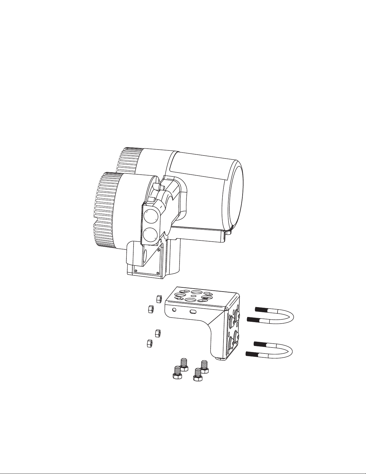
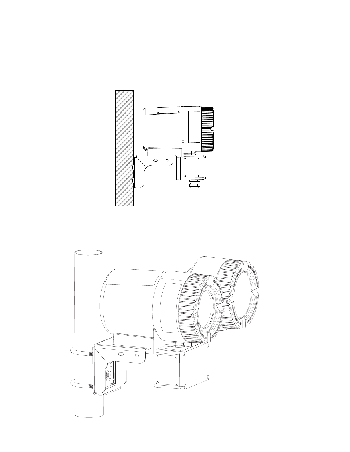
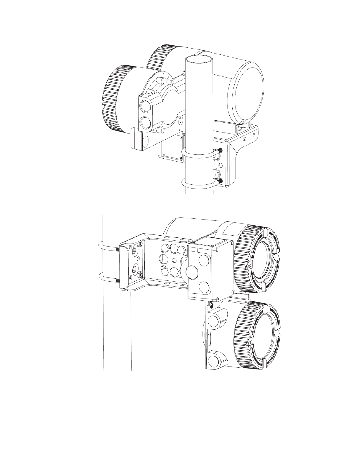
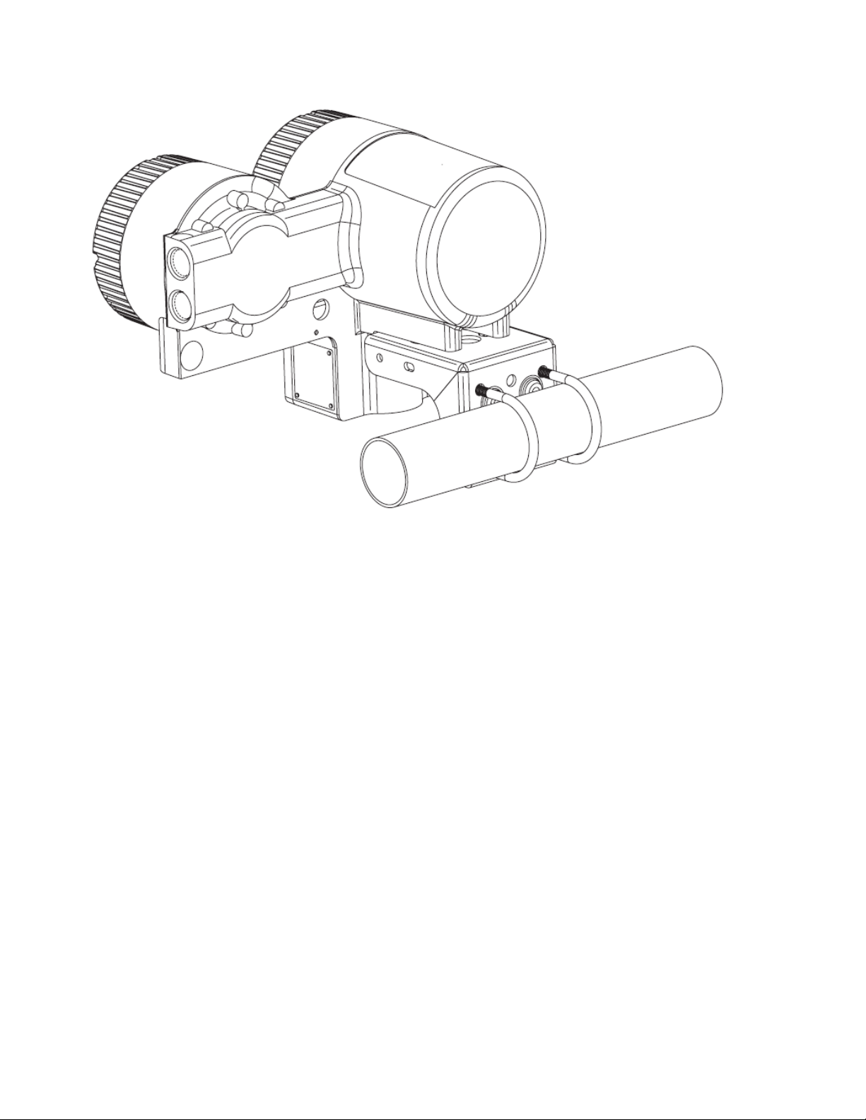
Mounting
Four 0.437-20 UNS threaded holes are provided on the surface of the enclosure on which a
carbon steel mounting bracket or optional stainless steel (SS) mounting bracket can be attached.
The other surface of the bracket allows for mounting to a surface, or to a nominal DN50 (2 inch)
vertical or horizontal pipe. An optional bracket is available for mounting to a DN80 (3 inch)
vertical or horizontal pipe. See Figure 2.
Figure 2. Transmitter Mounting
23
Page 24
MI 019-140 – November 2019 2. Installation
Positioning the Housing
The housing can be positioned at almost any angle in a horizontal plane by loosening the bracket
bolt and turning the housing with respect to the mounting bracket. See Figure 2.
The CFT51 transmitter can be mounted to a wall as displayed in Figure 3.
Figure 3. Wall Mounting
The transmitter can be mounted horizontally or vertically to a pipe. Some of the more common
mounting configurations are shown in Figures 4, 5, 6 and 7.
Figure 4. Vertical Pipe Mounting - Orientation 1
24
Page 25
2. Installation MI 019-140 – November 2019
Figure 5. Vertical Pipe Mounting - Orientation 2
Figure 6. Vertical Pipe Mounting - Orientation 3
25
Page 26
MI 019-140 – November 2019 2. Installation
Figure 7. Horizontal Pipe Mounting
26
Page 27
2. Installation MI 019-140 – November 2019
NOTE
LOCAL DISPLAY/
CONFIGURATOR
LONG SCREWS (2)
DISPLAY
BEZEL
CAPTIVE
SCREWS (3)
SHORT SCREW
(ROTATABLE)
FERRITE BEAD BRACKET
DAMPENER FOAM
Rotating the Display
The Display/Configurator can be rotated in 90 degree increments in the display bezel. The
display bezel does not rotate, and must always be mounted in the housing in the orientation
shown in Figure 8.
Figure 8. Display Orientation
To rotate the display to the desired orientation:
1. Remove the display assembly by loosening the captive screws.
2. Remove the short screw that retains the ferrite bead bracket and the dampener foam to
the back of the molding. Be careful to retain the screw for reassembly.
3. Remove the Local Display/Configurator from the Display Bezel by removing the long
screws that retain the assembly to the front of the molding.
4. Rotate the Local Display/Configurator to the desired orientation with the display
assembly molding and feed the cable of the Local Display/Configurator through the
corresponding opening in the molding.
5. Attach the Local Display/Configurator to the bezel using the long screws.
6. Place the dampener foam and the bracket over the ferrite bead on the cable and attach
the Local Display/Configurator to the Display Bezel using the short screw.
7. Place the reassembled display assembly in line with the required orientation as shown.
8. Attach the assembly to the housing using the captive screws.
The display bezel is not rotatable. The bezel must always be aligned with the housing
as shown in Figure 8 to retain the jumper configurations on the electronic module.
27
Page 28

MI 019-140 – November 2019 2. Installation
NOTE
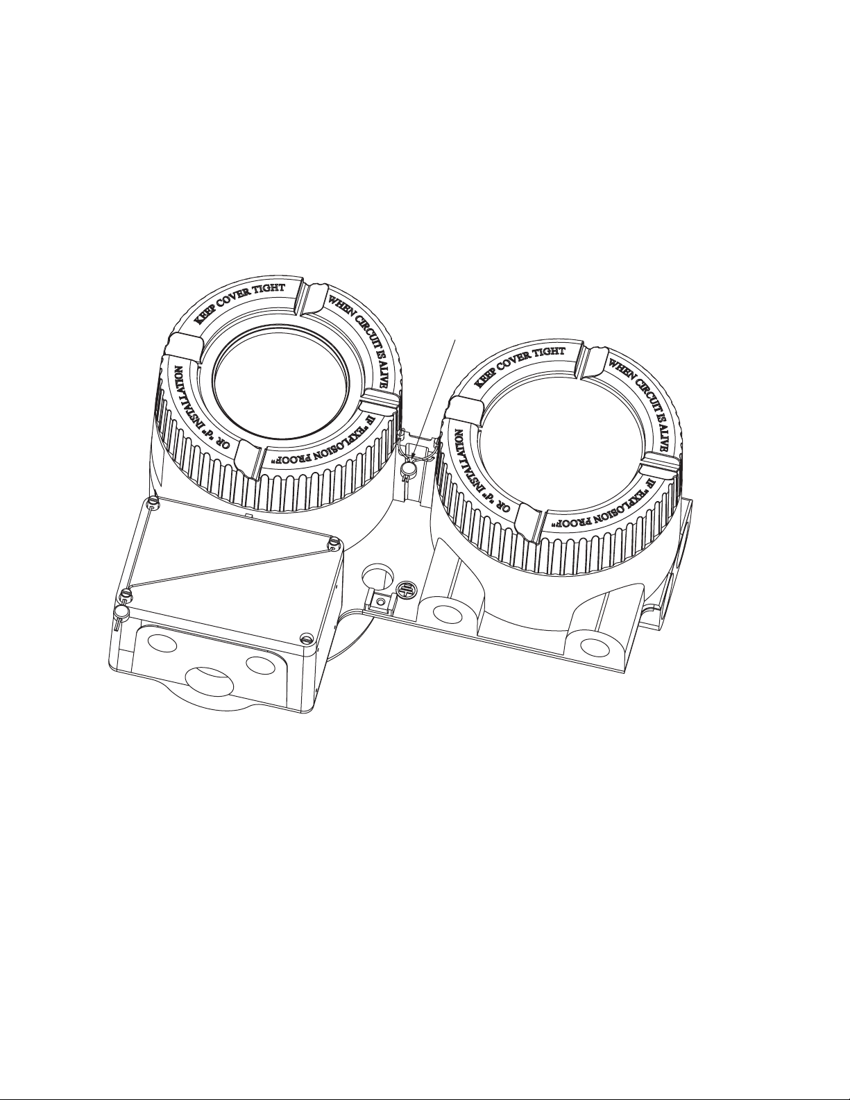
Cover Lock Versions
Various lock and seal mechanisms are available with the CFT51. One or more of these locking
mechanisms may be required for specific applications.
For all model code selections, locking pins are provided for the round electronic
housing covers (Figure 9). These cover locking mechanisms are required for all agency
flameproof applications.
For the Tamperproof Sealing (-S), U.S. Weights and Measures Custody Transfer
NTEP (-T), and Weights and Measures Industry Canada Approvals (-D) model code
selections:
Locking pins are provided with an additional seal wire and crimp seal for the
round electronic housing covers (Figure 10).
Additional locking mechanisms are provided for the transmitter junction box
(Figure 17) and flowtube junction box (CFS10 and CFS20 flowtubes only,
Figure 18).
The U.S. Weights and Measures Custody Transfer NTEP (-T) and Weights and
Measures Industry Canada Approvals (-D) model code selections are applicable only
when the transmitter is used with CFS10 or CFS20 flowtubes.
28
Page 29

2. Installation MI 019-140 – November 2019
LOCKING PINS
Locking Pins
To lock the two round transmitter housing covers, unscrew each locking pin (provided with all
model code selections) until approximately 6 mm (0.25 in) engages the groove on the cover. Note
that the two round transmitter housing covers must be locked for all agency (ATEX, CSA, FM,
IECEx) flameproof certifications.
Figure 9. Cover Locking Pins for All Model Code Selections
29
Page 30
MI 019-140 – November 2019 2. Installation
Wire and Seal Installed
Wire Seals
For the Tamperproof Sealing (-S), U.S. Weights and Measures Custody Transfer NTEP (-T), and
Weights and Measures Industry Canada Approvals (-D) model code selections, perform the
following steps to lock and seal the transmitter housing covers (Figure 10), the transmitter
junction box (Figure 17), and the flowtube junction box (CFS10 and CFS20 flowtubes only,
Figure 18):
Figure 10. Cover Locks for Tamperproof Sealing (-S), U.S. Weights and Measures Custody Transfer
NTEP (-T), and Weights and Measures Industry Canada Approvals (-D) Model Code Selections
30
Page 31

2. Installation MI 019-140 – November 2019
Slots in Screws
Holes in Housing
1. Lock and seal the round transmitter housing covers:
a. Install the cover lock screws so that the slots in the screws align with the holes in
the housing. The screws will stick out approximately ¼ inch. See Figure 11.
Figure 11. Aligning Cover Lock Screws with Housing
31
Page 32

MI 019-140 – November 2019 2. Installation
Install the wire through
the holes in the housing
Pull the wire all the
way through the holes
The wire should contact
the transmitter housing
Figure 12. Inserting the Wire in the
Holes in the Housing
Figure 13. Pulling the Wire Through
the Housing
b. Insert one end of the seal wire through each of the two holes in the housing and
corresponding slots in the locking screws, and pull both ends of the wire until it
contacts the housing. See Figure 12 and Figure 13.
32
Page 33

2. Installation MI 019-140 – November 2019
Housing
Holes in
c. Insert one end of the seal wire through each of the two holes in the locking screws
and pull both ends of the wire until snug. See Figure 14.
Figure 14. Pulling the Wire Through the Housing Screws
Holes in
Screws
33
Page 34

MI 019-140 – November 2019 2. Installation
Figure 15. Inserting Both Ends of the Wire
Through the Seal
Figure 16. Positioning the Seal and Crimping the
Wire
Insert both ends of the wire
Seal is all the way up
d. Insert both ends of the seal wire through the hole in the seal. Slide the seal up on
the wires until the seal is close to the housing, and crimp the seal on the wires to
secure them. See Figure 15 and Figure 16.
through the hole in the seal
and the wires are crimped
34
Page 35

2. Installation MI 019-140 – November 2019
2. Lock the transmitter junction box (Figure 17):
a. Slide one end of the seal wire through the holes in the three elongated cover screws
as shown.
b. Slide the other end of the wire through the bottom screw as shown, checking that
both ends of the wire pass through the hole in the screw.
c. Slide the seal onto both wire ends and crimp the seal as shown.
Figure 17. Transmitter Junction Block - Cover Locks
35
Page 36

MI 019-140 – November 2019 2. Installation
NOTE
3. Lock the flowtube junction box (CFS10 and CFS20 flowtubes only; Figure 18):
a. Slide one end of the seal wire through the holes in the three elongated cover screws
as shown.
b. Slide the other end of the wire through the bottom screw as shown, checking that
both ends of the wire pass through the hole in the screw. This is important to
ensure that each screw cannot be removed by independent sequential loosening of
the screws.
c. Slide the seal onto both wire ends and crimp the seal as shown.
Figure 18. Flowtube Junction Box
For additional information on cover locks for flowtube models CFS10 and CFS20,
refer to MI 019-120.
36
Page 37

BK
BU
BK
GN
RD
BK
WH
BK
BN
BK
YE
BK
WH
BK
BN
BK
YE
BK
BK
BU
BK
GN
RD
BK
WIRE PAIRS
FROM FLOWTUBE
WIRE PAIRS
TO TRANSMITTER
WIRE PAIRS
FLOWTUBE
JUNCTION BOX
TO TRANSMITTER
JUNCTION BOX
GROUND
Cable to
Flowtube
Description
1+
2C
34+
56+
78+
9-
+01
11 12 +
13 14 +
15 16 +
17 -
desU toN---81
Contact Output (DOUT)
Contact Input (DIN)
Current Output (MA2) 4-20 mA
Current Output (MA3) 4-20 mA
Pulse Output 2
Terminal
Modbus
Current Output (MA1)
4-20 mA with HART
Pulse Output 1
Terminal Wire Color Signal
1 Black
2 Blue
3 Black
4 Green
5 Red
6 Black
7 Black
8 Yellow
9 Black
10 Brown
11 Black
12 White
Driver 2
Driver 1
CFT51 Junction Box Wiring
RTD
RTD
Sensor B
Sensor A
See individual wiring sections
for power requirements.
See MI 019-120 for detailed
flowtube wiring instructions.
Power
2. Installation MI 019-140 – November 2019
Wiring
The installation and wiring of your transmitter must conform to local code requirements. See
Figure 19 for an overview of transmitter wiring with a CFS10 or CFS20 flowtube.
Figure 19. Overview of Transmitter Wiring with a CFS10 or CFS20 Flowtube
gniriW O/I 15TFC
CFT51
Shield Screw
CFS10/CFS20
TO TRANSMITTER
37
Page 38

MI 019-140 – November 2019 2. Installation
!
!
Field Wiring
To access the transmitter field terminals, remove the field wiring compartment cover by turning it
counterclockwise. The field wiring compartment cover is the one closest to the conduit openings.
See Figure 20.
When replacing the cover, tighten it until the cover meets the housing metal-to-metal.
DANGER
HAZARD OF ELECTRIC SHOCK, EXPLOSION, OR ARC FLASH.
In hazardous locations, do not remove cover while circuits are live.
Failure to follow these instructions can result in death or serious injury.
CAUTION
EQUIPMENT OPERATION HAZARD
Field wiring must be rated for 77°C or higher.
Failure to follow these instructions can result in injury or equipment damage.
38
Page 39

2. Installation MI 019-140 – November 2019
I/O WIRING
PORT
POWER WIRING PORT
EXTERNAL GROUND TERMINATION
GROUND PORT
SENSOR PORT
(1/2 NPT or M20)
(1/2 NPT or M20)
(1/2 NPT or M20)
(1/2 NPT or M20)
COMPARTMENT
ELECTRONICS MODULE
COMPARTMENT
FIELD WIRING
Figure 20. Accessing Field Terminals
The field wiring terminal board is shown in Figure 21.
39
Page 40

MI 019-140 – November 2019 2. Installation
W/ HART
Figure 21. Field Wiring Terminal Board
40
Page 41

2. Installation MI 019-140 – November 2019
GROUND
TERMINATION
WIRE TIE
HOLDER
POWER WIRE
TERMINATIONS
Transmitter Power Wiring
Connect the power wiring to the field wiring terminal board. Shielded wire should be used on the
dc version. Connect the shield on both ends.
Figure 22 shows an illustration for the power I/O wiring.
Figure 22. Transmitter Power Wiring
41
Page 42

MI 019-140 – November 2019 2. Installation
Transmitter ac Power Supply
Figure 23. Transmitter ac Power Connection Terminals
Table 5. Power (Limits): 102 to 264 Vac; 47 to 63 Hz
1Line
2 Neutral
42
Page 43

2. Installation MI 019-140 – November 2019
Transmitter dc Power Supply
Figure 24. Transmitter dc Power Connection Terminals
Table 6. dc Power: 10-36 Vdc
1 Positive dc connection
2 Negative dc connection
43
Page 44

MI 019-140 – November 2019 2. Installation
NOTE
Input/Output Wiring
The CFT51 supports multiple I/O options, both isolated and non-isolated, which require
external power source.
However, if only one power source is available, the + terminals of the I/Os can be connected
together. In this case the I/Os are no longer isolated from each other.
In addition, for backward compatibility with existing CFT50 installations, the + terminals can all
be connected together and powered by the same power source.
Table 7. I/O Wiring
Terminal Description
1+
Modbus 2C
3-
4+
5-
6+
7-
8+
9-
10 +
11 -
12 +
13 -
14 +
15 -
16 +
17 -
18 --- Not Used
Current Output (MA1)
4-20 mA with HART
Pulse Output 1
Contact Input (DIN)
Current Output (MA2) 4-20 mA
Current Output (MA3) 4-20 mA
Pulse Output 2
Contact Output (DOUT)
44
All outputs must be externally powered by nominal 24 Vdc.
Page 45

2. Installation MI 019-140 – November 2019
NOTE
OPTIONAL LINE TERMINATION
RESISTORS (150 OHM, 0.5 W)
MODBUS
MASTER
MODBUS
SLAVE
DEVICE
MODBUS
SLAVE
DEVICE
MODBUS (D0)
TERMINAL (1)
MODBUS (D1)
TERMINAL (3)
(2)
C
C
OPTIONAL COMMON
CONNECTION
MODBUS (COM)
CFT51
+
C
-
Modbus Wiring
Figure 25 shows the typical connection of the Modbus-configured CFT51 Transmitter to a
Modbus master. It may be necessary to install the optional termination resistor to reduce signal
reflections on long cable length interconnections. It may also be necessary to reverse the Modbus
signal wires for some Modbus masters to keep the proper D0 and D1 signaling convention.
Follow Modbus wiring guidelines and requirements as documented online at
www.modbus.org.
Figure 25. Typical Modbus Wiring
The maximum length of signal wires for Modbus communications is 1000 m (3280 ft), operating
at the default 9600 baud rate, running 26 AWG and 150 ohm terminator resistor. Use twisted
shielded wire. Connect shield on both ends.
For systems with a common connection, use dual twisted shielded wire. One twisted pair for D0
and D1 and the other twisted pair shorted together on both ends for the common connection.
45
Page 46

MI 019-140 – November 2019 2. Installation
NOTE
CURRENT OUTPUT MA1
CURRENT OUTPUT
TERMINAL (5)
POSITIVE POWER
INPUT TERMINAL (4)
+
-
HART COMMUNICATOR
CONTROLLER
OR RECORDER
INDICATOR
POWER
+
+
+
-
-
-
SUPPLY
+
+
-
-
24 Vdc
POSITIVE POWER INPUT
TERMINALS (10, 12)
CURENT OUTPUT
TERMINALS (11, 13)
LOOP
LOAD
CURRENT OUTPUT MA2 and MA3
+
-
Current Output MA1 and HART Communication Interface
The HART communications interface, superimposed on the 4-20 mA signal, is
available only on Current Output (MA1).
The maximum length of signal wires for HART communication is 3,050 m (10,000 ft). It is
1,525 m (5,000 ft) in HART digital multidrop mode. Current Output 1 must have a minimum
loop load of 250 ohms when HART communications is used.
CFT51 transmitters with HART communication are factory-configured to poll address 0,
allowing them to operate in the standard point-to-point manner superimposed on the 4-20 mA
signal.
Figure 26. Typical HART Wiring (Current Output MA1)
Current Outputs MA2 and MA3
The loop load resistor can be a value from 0 to 683
add the series resistance of each component in the loop, excluding the transmitter.
Figure 27. Current Output Wiring (MA2 and MA3)
To determine your loop load resistance,
46
Page 47

2. Installation MI 019-140 – November 2019
CONTACT
POSITIVE POWER INPUT
TERMINAL (8)
CONTACT INPUT
TERMINAL (9)
24 Vdc
+-
-
+
CONTACT INPUT DIN
+
-
*
* For example, DO Module
POSITIVE POWER INPUT
TERMINAL (16)
CONTACT OUTPUT
TERMINAL (17)
LOAD *
24 Vdc
+
-
+
-
CONTACT OUTPUT DOUT
+
-
* For example lamp, relay, coil
Contact Input (DIN)
Figure 28. Contact Input Wiring (DIN)
The voltage requirement for Discrete Input (DIN) is 24 Vdc ±10%. The load requirement is
limited to producing a maximum current of 100 mA.
Contact Output (DOUT)
Figure 29. Contact Output Wiring (DOUT)
The voltage requirement for Discrete Output is 24 Vdc ±10%. The load requirement is limited to
producing a maximum current of 100 mA.
47
Page 48

MI 019-140 – November 2019 2. Installation
POSITIVE POWER
INPUT TERMINAL (6, 14)
PULSE OUTPUT
TERMINAL (7, 15)
RECEIVER
24 Vdc
+
-
-
+
PULSE OUTPUT 1 or 2
+
-
OPTIONAL
RECEIVER
24 Vdc
+
POSITIVE POWER
INPUT TERMINAL (6, 14)
TERMINAL (7, 15)
+
-
PULSE OUTPUT
TERMINAL (7, 15)
-
PULSE OUTPUT 1 or 2
+
-
OPTIONAL
R
Pulse Outputs 1 and 2
The pulse output (Pulse Output 1 and Pulse Output 2) signal is typically used with a receiver
such as an external totalizer or control system. The pulse output is a high side switch or sourcing
output. If the receiver requires a sourcing input and is internally current limited, it can be
connected as shown in Figure 30.
Figure 30. Pulse Output with a Sourcing Input Receiver (with Internal Current Limiting,
Pulse Output 1 or Pulse Output 2)
For receivers requiring a sourcing input but without internal current limiting, a resistor is required
to limit the current to that specified by the receiver as shown in Figure 31. The pulse output
current is limited to 80 mA maximum.
For example:
V = 24 Vdc
I = 80 mA
R
300 Ohms
Figure 31. Pulse Output with a Sourcing Input Receiver (without Internal Current Limiting,
Pulse Output 1 or Pulse Output 2)
48
Page 49

2. Installation MI 019-140 – November 2019
POSITIVE POWER
INPUT TERMINAL (6, 14)
PULSE OUTPUT
TERMINAL (7, 15)
24 Vdc
+
-
RECEIVER
+
-
R
PULSE OUTPUT 1 OR 2
+
-
OPTIONAL
POSITIVE POWER
INPUT TERMINAL (6, 14)
PULSE OUTPUT
TERMINAL (7, 15)
RECEIVER
R1
R2
I
bias
(OPTIONAL)
+
-
PULSE OUTPUT 1 OR 2
+
-
V
int
24 Vdc
If the receiver requires a current sinking input (such as a contact closure or transistor switch), a
resistor is required across the receiver terminals as shown in Figure 32. The resistor should be sized
to limit the on-state current in the pulse output to 80 mA maximum.
Figure 32. Pulse Output with a Receiver Requiring a Sinking Input (Pulse Output 1 or
Pulse Output 2)
Because of the internal bias currents produced by some receivers requiring sinking inputs, a
resistor divider may be necessary to help ensure that the low input threshold requirement of the
receiver is met. This configuration is shown in Figure 33. R1 and R2 must limit the pulse output
on-state current to 80 mA maximum.
Figure 33. Pulse Output with a Sinking Input Receiver Using a Divider Network (Pulse Output 1 or
Pulse Output 2)
49
Page 50

MI 019-140 – November 2019 2. Installation
NOTE
NOTE
NOTE
HOST
MODEM
POWER
SUPPLY
LOAD
CFT51CFT51 CFT51
HART Digital Multidrop Communication
“Multidrop” refers to the connection of several transmitters to a single transmission line. You can
configure HART communications using the pushbuttons on the LCD indicator. Communication
between the host computer and the transmitters takes place digitally.
On selecting multidrop communication while you configure HART version 5, the
first analog output of the transmitter is deactivated. First analog output deactivation is
optional for HART versions 6 and higher.
With the HART digital communications protocol, up to 63 transmitters can be connected on a
single twisted pair of wires or over leased telephone lines.
The application of a multidrop installation requires consideration of the update rate necessary
from each transmitter, the combination of transmitter models, and the length of the transmission
line. Communication with the transmitters can be accomplished with any HART compatible
modem and a host implementing the HART protocol. Each transmitter is identified by a unique
address (1-63 for HART versions 6 and higher, or 1-15 for HART version 5) and responds to the
commands defined in the HART protocol.
Figure 34 shows a typical HART digital multidrop network. Do not use this figure as an
installation diagram.
Follow HART Communications guidelines and requirements as documented online
at www.hartcomm.org.
Figure 34. Typical HART Multidrop Network
CFT51 transmitters with HART communication are set to poll address 0 at the
factory, allowing them to operate in the standard point-to-point manner
superimposed on a 4 to 20 mA output signal. To activate multidrop communication,
the transmitter address, when configured with HART version 6 or greater, must be
changed to a number from 1 to 63. Each transmitter must be assigned a unique
number on each multidrop network.
50
Page 51

2. Installation MI 019-140 – November 2019
TRANSMITTER TERMINALS
CABLE SHIELD TERMINATION
GROUND TERMINATION
(TRANSMITTER END ONLY)
Transmitter Wiring Connections from Flowtube
Connect the wiring from the flowtube to the transmitter per Figure 35 and Table 8. Distance
between the flowtube and transmitter can be up to 305 m (1000 ft) with CFS10 or CFS20
flowtubes.
Connect the “dressed” end of the factory-supplied cable to the transmitter terminals. To facilitate
wire identification, ensure that the proper wire pairs remain twisted, as the black wires are not
common.
Figure 35. Transmitter Junction Box
Table 8. Transmitter Junction Box Wiring
Terminal Wire Color Signal
1Black
2Blue
3Black
4 Green
5Red
6Black
7Black
8Yellow
9Black
10 Brown
11 B l ac k
12 White
(CFS10 and CFS20 only)
RTD
RTD
Sensor B
Sensor A
Driver 2
Driver 1
51
Page 52

MI 019-140 – November 2019 2. Installation
NOTE
NOTE
BACK
ENTER
ESC
NEXT
1
WritProt
Disabled
Write Protect Jumper
The write protection jumper, located on the printed wiring board shown in Figure 37, allows or
prevents anyone from changing the configuration of the transmitter or resetting the grand
totalizers. (Batch totalizers, however, can still be changed.) This feature is usually used in custody
transfer applications, or to ensure that the configuration and/or totals are not changed.
The jumper is usually placed in the “disabled” (factory default) position. Placing the jumper in
the “enabled” position engages the write protection feature.
If write protection is enabled and someone tries to enter Quick Start mode, enter Setup mode, or
reset the totals, the display reads WPROT/LOCKED.
A change in the write protect jumper position takes effect immediately.
When the CFT51 is configured with the U.S.
Weights and Measures Custody Transfer NTEP (-T)
or Weights and Measures Industry Canada Approvals
(-D) model code options (available only with CFS10
and CFS20 flowtubes), the transmitter displays the
message WritProt Disabled when the write
protection jumper is disabled.
Figure 36. Write Protect Jumper Location
52
Page 53

2. Installation MI 019-140 – November 2019
WRITE PROTECT DISABLED
WRITE PROTECT ENABLED
Figure 37. Write Protect Jumper Position
53
Page 54

MI 019-140 – November 2019 2. Installation
54
Page 55

3. Quick Start
NOTE
NOTE
The CFT51 Transmitter can be configured with the local keypad/display, with a HART
communicator, or with the Modbus protocol interface. With any of these options, two
configuration menus exist, Quick Start and Setup. Most basic applications can be configured in
Quick Start mode; other applications require using Setup mode.
If write protection is enabled, the display reads WPROT/LOCKED and you cannot enter
Quick Start or Setup mode. To disable write protection, you must first turn the power
off, move the write protect jumper to the disable position, and then turn the power
back on. See “Write Protect Jumper” on page 52.
When to Use Quick Start Mode
Quick Start mode can be used for applications requiring only:
Flow measurement in the currently selected units. (The factory default is mass flow in
lb/min.)
Positive flow direction.
Use Setup mode (described in “Setup” on page 151) for applications involving:
Volume flow or density measurements
Mass flow units other than the currently selected units
Pulse or multiple Contact Outputs
Alarm or Totalizer functions
Reverse or bidirectional flow.
Flowtube information, including the flowtube model and calibration coefficients, must be entered
in the CFT51 transmitter. The CFT51 transmitter requires three flowtube coefficients: FC2,
DC2, and DC4.
Flow and density coefficients must be entered in real number decimal format (such as
+0.003452), where previous CFT transmitters used exponential format (such as
+3.54062E+02).
55
Page 56

MI 019-140 – November 2019 3. Quick Start
CFS10-##
FLOWTUBE SIZE
02 = 1/8
" (3 mm)
03 = 1/4" (6 mm)
05 = 1/2
" (15 mm)
08 = 3/4
" (20 mm)
10 = 1" (25 mm)
15 = 1.5 " (40 mm)
20 = 2" (50 mm)
CFS20-##
FLOWTUBE SIZE
15 = 1.5
" (40 mm)
30 = 3.0
" (80 mm)
CFS20-**#
FLOWTUBE MATERIAL
CFS10-**#
S = 316L
H = Nickel alloy
C = 316L (Sanitary)
Steps Required
1. Obtain the flowtube constants (FC and DC coefficients) from the calibration sheet
shipped with the flowtube (or from the flowtube data label).
2. Obtain the flowtube size from the model code on the flowtube data label; for example:
3. Obtain the flowtube material from the model code on the flowtube data label. The
material code is the letter that follows the flowtube size in the model code.
S AISI Type 316L wetted material
(1)
H Nickel alloy equivalent to Hastelloy
®
wetted material
C AISI Type 316L wetted material for sanitary applications
4. Mount the flowtube per MI 019-120 or MI 019-125, as applicable; mount the
transmitter per “Mounting” on page 23 of this document.
5. Install wiring: power to transmitter, flowtube to transmitter, transmitter input/output
wiring per “Wiring” on page 37.
Refer to “Procedure Using Keypad/Display” on page 57 or “Procedure Using the HART
Communicator” on page 60 to finish the startup procedure.
1. Hastelloy is a registered trademark of Haynes International, Inc.
56
Page 57

3. Quick Start MI 019-140 – November 2019
1 QSTART
OFFLINE?
2 MA1 URV
2 MA1 LRV
3 VALUE
3 CALZERO
3 FC2
3 DC2
ONLINE?
3 DC4
PASSWORD
1MEASURE
3 SIZE
3 MATL
2 UNITS
(displayed
measurement)
NOTE
Complete the entire Quick Start
(SETUP) procedure at least once.
FOR MODBUS PROTOCOL
FOR HART PROTOCOL
2 TUBE
2 FLOWZER
3 RESTORE
2 BAUD
2 PARITY
2 DEVADR
Procedure Using Keypad/Display
The following section shows the Quick Start menu available on the local display and describes
using the local keypad and display to execute the Quick Start procedure. Refer to “Using the
Local Display” on page 61 for additional information on using the local keypad and display
buttons.
The Keypad/Display Quick Start menu is shown in Figure 38.
Figure 38. Keypad/Display Quick Start Menu
57
Page 58

MI 019-140 – November 2019 3. Quick Start
NOTE
Perform the following steps to execute the Quick Start procedure from the local keypad and
display:
1. Press the Left arrow key until the display reads 1 MEASURE and follow the menu using
the keys as explained in Table 9 and shown in Figure 40.
Table 9. Operation of Function Keys
Key Function
Left Arrow (ESC) Moves left in the menu structure.
Moves the cursor to the left in a data entry field.
Escapes from changes in a picklist menu or data entry. (a)
Answers No.
Right Arrow (ENTER) Moves right in the menu structure.
Used to access the data entry edit mode of a parameter.
Moves the cursor to the right in a data entry field.
Enters and saves the changed menu picklist choices or data entry. (a)
Answers Yes.
Up Arrow (
Down Arrow (NEXT) Moves downward in the menu structure or a picklist menu.
a. On data entry, repeatedly press the key until the cursor reaches the end of the display.
BACK) Moves upward in the menu structure or a picklist menu.
2. Go to 1 QSTART > 2 TUBE > 3 SIZE and select the flowtube size code. Then go to
3 MATL and select the flowtube material code.
3. Go to 3FC2, and enter flow constant FC2. Flow constants FC1 and FC3 are
calculated by the transmitter.
4. Go to 3DC2, and enter density constant DC2. Then go to 3 DC4 and enter the
density constant DC4. Density constants DC1 and DC3 are calculated by the
transmitter.
5. Apply flow to your flowmeter for 5 to 10 minutes.
6. Establish zero flow by closing block valves to ensure no fluid movement. The tube
must be completely filled with fluid.
7. Go to
3CALZERO. Press the Enter key to start the zeroing process. The display reads
BUSY until the process is finished and then reads DONE.
The transmitter is zeroed at the primary zero (1). To use the secondary zero (2), you
must use Setup mode.
Press the Down arrow key to display 3 VALUE, the amount of offset that is necessary
to make the transmitter read zero at zero flow conditions. You can then manually
change this value if necessary (for example, if the flowmeter cannot be blocked in at
no-flow condition) using the Left/Right and Up/Down arrow keys as explained in
Table 9. Lastly, you can press the Down arrow key to display
Enter key at this point changes the manually entered value back to the last
3RESTORE. Pressing the
CALZERO
offset value.
58
Page 59

3. Quick Start MI 019-140 – November 2019
8. Depending on the selected communication protocol, do the following:
With HART Communication protocol:
a. Go to 2 UNITS to view the current units.
b. Go to 2 MA URV and enter your upper range value in the current units.
c. Go to 2 MA LRV and enter your lower range value in the current units.
With Modbus protocol:
a. Go to 2 BAUD and enter a baud rate of 1200, 2400, 4800, 9600, 19200, or
38400.
b. Go to 2 Parity and enter none, even, or odd.
c. Go to 2 DEVADR and enter your device address from 1 to 247.
9. Go to 2 TUBE. Press the Left arrow key to go to ONLINE?. Pressing the Enter key to
answer Yes takes you to 1 QSTART. Press the Up arrow key to go to 1 MEASURE and
the Left arrow key to return to Measure mode.
10. For CFS10 and CFS20 flowtubes only:
a. Go to CALIB menu in SETUP, press the Down arrow and select the TUBECHK menu
and press Enter.
b. Press the Down arrow key to DATUM. Enter the Meter Verification Value (MVV)
from the data plate or calibration sheet.
c. Press the Up arrow key to CHECK. Press the Right arrow key and RUN TEST. After
the test has completed, save as “Ratio.”
59
Page 60

MI 019-140 – November 2019 3. Quick Start
2 Online
1 Measure
2 Quick Start
2 Flow Constants
3 Density Constants
4 Flow Zero
5 URV
6 LRV
1 Model
Procedure Using the HART Communicator
The following section shows the Quick Start menu available from the HART Communicator and
describes using the HART Communicator to execute the Quick Start procedure.
The HART Communicator Quick Start Menu is shown in Figure 39.
Figure 39. HART Communicator Quick Start Menu
Perform the following steps to execute the Quick Start procedure from the HART
Communicator:
1. Go to 2 Online.
2. Go to 2 Quick Start.
3. Go to 1 Model and select your flowtube.
4. Go to 2 Flow Constants and enter flow constant FC2. Flow constants FC1 and
FC3 are calculated by the transmitter.
5. Go to 3 Density Constants and enter density constants DC2 and DC4. Density
constants DC1 and DC3 are calculated by the transmitter.
6. Apply flow to your flowmeter for five to ten minutes.
7. Create zero flow by closing block valves to ensure no fluid movement.
8. Go to
9. Go to
4 Flow Zero and zero your flowmeter.
5 URV and enter your upper range value.
10. Go to 6 LRV and enter your lower range value.
11. For CFS10 and CFS20 flowtubes only:
a. Go to CALIB menu in SETUP, press the Down arrow and select TUBECHK menu
and press Enter.
60
b. Press the Down arrow key to DATUM, and enter the Meter Verification Value (MVV)
from the data plate or calibration sheet.
c. Run the Meter Verification function and save as a “Ratio.”
Page 61

4. Using the Local Display
BACK
ENTER
ESC
NEXT
Using the Local Display
A local display, as shown in Figure 40, provides local indication of measurement, status, and
identification parameters. The display also provides a means of performing quick start,
configuration, calibration, and self-test. Operation is accomplished via four multi-function keys.
Figure 40. Local Display
Table 10. Operation of Function Keys
Key Function
Left Arrow (ESC) Moves left in the menu structure.
Right Arrow (ENTER) Moves right in the menu structure.
Up Arrow (
Down Arrow (
a. On data entry, repeatedly press the key until the cursor reaches the end of the display.
BACK) Moves upward in the menu structure or a picklist menu.
NEXT) Moves downward in the menu structure or a picklist menu.
Moves the cursor to the left in a data entry field.
Escapes from changes in a picklist menu or data entry. (a)
Answers No.
Used to access the data entry edit mode of a parameter.
Moves the cursor to the right in a data entry field.
Enters and saves the changed menu picklist choices or data entry.
Answers Yes.
(a)
61
Page 62

MI 019-140 – November 2019 4. Using the Local Display
NOTE
1 MEASURE
1 QSTART
1 STATUS
1 SETUP
Measurement
Parameters
Quick Start
Parameters
Status
Parameters
Setup
Parameters
FOR DETAILS SEE
“MEASURE MODE” ON
PA GE 6 3 .
THIS IS THE NORMAL OPERATION MODE. IT
DISPLAYS CONFIGURED MEASUREMENTS. IT
ALSO INDICATES IF ALARM OR DIAGNOSTIC
CONDITIONS EXIST. THE SELECTED DEFAULT
MEASUREMENT IS DISPLAYED WHEN THE
TRANSMITTER IS TURNED ON.
FOR DETAILS SEE
“STATUS MODE” ON PAGE 66,
THIS MODE PROVIDES DETAILS ABOUT THE
TRANSMITTER MODE, ALARM, AND OUTPUT
VALUES, STATE OF CONTACT INPUTS AND
OUTPUTS, FLOW DIRECTION, DIAGNOSTIC
ERRORS, AND MORE. ALARMS CAN ALSO BE
CLEARED IN THIS MODE.
THIS MODE IS USED TO DISPLAY REFERENCE
INFORMATION SUCH AS MODEL CODE AND
SERIAL NUMBER, CALIBRATION DATE, AND.
SOFTWARE VERSION.
THIS MODE IS USED TO CUSTOMIZE
(CONFIGURE) THE TRANSMITTER TO YOUR
APPLICATION. THIS INCLUDES DEFINING
UPPER AND LOWER RANGE VALUES, OUTPUT
USED, ALARM CONDITIONS, AND SO FORTH.
FOR DETAILS SEE
“SETUP” ON PAGE 151 AND
“SETUP DIAGRAMS” ON
PAGE 227.
1 VIEW
Parameters
FOR DETAILS SEE
“VIEW MODE” ON PAGE 70.
THIS MODE CAN BE USED TO QUICK START
YOUR TRANSMITTER IF MEASUREMENT IS
MASS FLOW IN UNITS OF LB/M, CURRENT
OUTPUT IS USED, FLOW DIRECTION IS
POSITIVE, AND NO SPECIAL FEATURES ARE
REQUIRED.
FOR DETAILS SEE
“QUICK START” ON PAGE 55.
View
Top Level Menu
The Top Level menu displays five modes – Measure, Quick Start, Status, View, and Setup. You
can switch from one to another in sequence by using the Up/Down arrow keys. To enter the
second level menu from a particular top level display, press the Right arrow key. To return to the
top level from a second level menu item, press the Left arrow key. The level of the first, second,
third, and fourth level menus is indicated by the digit appearing as the first character in Line 1 of
the display; “1” indicates Level 1 (Top Level), “2” indicates Level 2, “3” indicates Level 3, and so
forth.
The top level menu is shown in Figure 41.
Figure 41. Top Level Modes and Their Basic Functions
62
Certain parameters may be missing as you step through the menus described in this
chapter, depending on the configuration of your instrument.
Page 63

4. Using the Local Display MI 019-140 – November 2019
NOTE
NOTE
Measure Mode
The Measure mode, which is your main operating mode, is displayed upon startup. Depending
on the transmitter configuration, it has up to 13 displays, any/all of which can be configured for
viewing. See “Display” on page 175. All such displays can be configured to be scrolled with the
Up/Down arrow keys or they can also be configured to cycle automatically from one to the other.
Mass Flow — Shows current mass flow rate (forward or reverse) in the selected
engineering units.
Vol um e Flow — Shows current volume flow rate (forward or reverse) in the selected
engineering units.
Density — Shows current density in the selected engineering units.
Concentration — Shows current percent concentration.
If the input(s) to the concentration measurement are out of range, or if the calculated
output is beyond the specified limits, an error message will alternate with the current
value: INP O/R - input (density or temperature) is out of range, or OUT O/R output (calculated concentration) is out of range.
Temperature — Shows current process temperature in the selected engineering units.
Totals 1, 2, 3, and 4 — Shows current totals in the selected engineering units.
If the totalizer measurement exceeds the configured format, the display will alternate
the message ROLLOVER with the current rollover value.
Component A and B Measurements — Shows current mass or volume flow rate
(forward or reverse) in the selected engineering units.
The transmitter can also be configured so that the readings on the measurement display blink
when an alarm and/or diagnostic condition is present. An arrow symbol also appears in the lower
right corner of the display when an alarm occurs. An Up arrow indicates a high alarm; a Down
arrow indicates a low alarm.
The transmitter has a feature which can produce compensated measurements in 2-phase
applications for greater accuracy. The symbol 2 appears in the lower right corner of the display if
2-phase flow is present. This symbol does not indicate that the 2-phase feature is configured “on.”
To activate the 2-phase feature, refer to “2 Phase” on page 183.
63
Page 64

MI 019-140 – November 2019 4. Using the Local Display
NOTE
NOTE
Configuring Totals
Totals 1, 2, 3, 4, and Pulse Totals 1 and 2 can be turned on, off, or cleared from the Measure
mode
Taking measurements online:
When using the local keypad push-button to reset Totalizers or to initiate Total Pulse, pressing
the ENTER key from the Measure mode will take the measurements off-line, which means:
4 to 20 mA outputs are held at the last value
Pulse output(s), if set to rate/frequency, are held at the last value, and
Pulse output(s), if set to total, are held at zero.
This condition will continue until you exit the off-line mode and return to Measure mode. If
you are idle for more than 10 minutes during the off-line mode, on-line operation
automatically resumes.
The menu selections to turn on, off, or clear the pulse totalizers do not appear in the
Measure mode unless that pulse output is configured for total mode.
Passwords can be employed to help protect the grand total(s) and batch total(s). The high level
password is required to clear a grand total. If both high and low level passwords are enabled, either
the high or low level password can be used to clear a batch total.
To perform this function:
1. Press the Right arrow key during any measurement display.
2. Enter the password (if passwords are employed).
3. Use the Down arrow key to select the desired total.
4. Select off, on, or clear and press Enter.
Total 1, Total 2, Total 3, and Total 4 can be individually cleared by an external
contact. An external contact can also be used to clear all batch totals or all grand
totals.
Totals can also be cleared using the HART Communicator or Modbus protocol.
If write protection is enabled, the display reads WPROT/LOCKED and you cannot reset
grand totals. Batch totals can be protected only by using the lower level password.
To disable write protection, move the write protect jumper to the “disable” position.
See “Write Protect Jumper” on page 52.
64
Page 65

4. Using the Local Display MI 019-140 – November 2019
1MEASURE
###.#
USG/M
VOLUME FLOW
MASS FLOW
###.#
LB/M
###.#
g/cc
###.#
% by wt
###.#
degF
###.#
LB
###.#
USGal
###.#
LB
DENSITY
CONCENTRATION
TEMPERATURE
TOTAL 1
TOTAL 2
TOTAL 3
PASSWORD
XXXXXX
TOTAL 1
off
on
clear
TOTAL 2
TOTAL 3
TOTAL 4
###.#
LB
TOTAL 4
PULSETOT1
COMPONENT A
COMPONENT B
COMPONENT A
COMPONENT B
###.#
LB/M
###.#
LB/M
###.#
USG/M
###.#
USG/M
PULSETOT2
OFFLINE?
ONLINE?
(similar to TOTAL1)
(similar to TOTAL1)
(similar to TOTAL1)
MASS FLOW
MASS FLOW
VOLUME FLOW
VOLUME FLOW
Figure 42. Measure Mode Structure Diagram
65
Page 66

MI 019-140 – November 2019 4. Using the Local Display
Quick Start Mode
Refer to “Quick Start” on page 55.
Status Mode
The Status mode enables you to view a number of system parameters and thus assess the
performance of the loop. You cannot edit them in this mode. To step through the displays of the
parameters, use the Up/Down arrow keys. The Status mode structure diagram is shown in
Figure 43.
In Alarm status, you can determine the number of alarms and a brief description of each. You can
also clear all alarms manually. In viewing the parameter 2 ALARMS, the display reads no alrms or
# alarms. If it reads # alarms, pressing the Right arrow key displays a brief description of the
first alarm condition. Using the Down arrow key, you can step through the list to view each
alarm. Press the Left arrow key to return to # alarms. Press the Right arrow key to obtain the
message ACK ALARMS?. Press the Right arrow key again to acknowledge all the alarms.
In Diagnostic status, you can view the diagnostic history of the instrument. You can also
acknowledge the active diagnostic manually. In viewing the parameter 2 DIAGS, the display reads
0 active or 1 active. If 1 active, press the Right arrow key to display the active diagnostic
condition code. Press it again to display the time the diagnostic condition occurred. This is
presented as the total number of hours the transmitter has been powered. Continue to use the
Down arrow key to step through the history of up to 10 diagnostic conditions. Press the Left
arrow key to return to # active. Press the Right arrow key to obtain the message ACK DIAGS?.
Press the Right arrow key again to acknowledge the active diagnostic condition.
66
Page 67

4. Using the Local Display MI 019-140 – November 2019
1 STATUS
2 MODE
MODE (On-Line Or Off-Line)
ALARM STATUS (Number of Alarms or No Alarms)
2 ALARMS
2 DIAGS
2 WPROT
2 MA1
2 MA2
2 MA3
2 PULSE 1
DIAGNOSTIC STATUS (Number of active diagnostic situations)
WRITE PROTECTION (On or Off)
MA1 OUTPUT VALUE (On or Off)
MA2 OUTPUT VALUE (On or Off)
MA3 OUTPUT VALUE (On or Off)
2FLOWDIR
2 DIN
2 DOUT
2TUBMODE
FLOW DIRECTION (Positive or Negative)
DISCRETE INPUT STATE (On or Off)
DISCRETE OUTPUT FUNCTION (On or Off)
FLOWTUBE MODE (offline, startup, or normal)
PULSE OUTPUT 1 VALUE (On or Off)
2TUBFREQ
2SENSAMP
FLOWTUBE FREQUENCY VALUE
SENSOR AMPLITUDE VALUE
2TUBDRIV
DRIVE CURRENT VALUE
(Alarms can also be viewed and acknowledged from here)
2VFRACT
VOID FRACTION (0 - 100%)
(Diagnostics can also be viewed and acknowledged from here)
2 RUNTIME
TIME IN SERVICE (hours)
2DRIVGAIN
DRIVE GAIN
2PRESSUR
PRESSURE COMPENSATION INPUT
2 PULSE 2
PULSE OUTPUT 2 VALUE (On or Off)
NOTE: SOME PARAMETERS MAY
NOT BE DISPLAYED DEPENDING
ON TRANSMITTER CONFIGURATION
Figure 43. Status Mode Structure Diagram
67
Page 68

MI 019-140 – November 2019 4. Using the Local Display
NOTE
Alarm Actions
Conditions That Can Be Alarmed
Alarms can be set for the high setpoint and low setpoint of mass flow, volume flow, density,
concentration, temperature, and component measurements. Alarms can also be set for the high
setpoint of each total measurement.
Actions of Transmitter During Alarm Conditions
Display — The display can be configured to respond or not respond to a specific alarm. The
display can be configured to blink or not blink in response to an alarm condition. An arrow
symbol also appears in the lower right corner of the display when an alarm occurs. An Up arrow
indicates a high alarm; a Down arrow indicates a low alarm.
Milliampere Outputs — Alarms can be configured to force the milliampere output associated
with the alarm to go fully upscale, fully downscale, be held at the last value, or ignore or do
nothing.
Pulse Outputs — Pulse Outputs 1 and 2 have the same options as mA outputs for alarms. Alarms
can be configured to force the pulse output associated with the alarm to go fully upscale, fully
downscale, be held at the last value, or ignore or do nothing.
Relay Contact Outputs — Contact output relay can be configured to respond or not respond to
a specific alarm.
Status Mode — Alarm conditions are defined in the status mode. Either Alarm or No Alrm is
displayed.
Acknowledging Alarms — The alarm acknowledge function can be configured as Auto or
Manual. In Auto, all evidence of the alarm clears when the alarm condition no longer exists. In
Manual, the alarm must be acknowledged manually.
Three methods are available to acknowledge alarms when they are configured for manual
acknowledgment. These methods are effective only after the condition that caused the alarm no
longer exists. The methods are:
Using the local keypad in Status mode. See “Status Mode” on page 66 for details.
Using the HART Communicator or Modbus protocol.
Using an external contact if the contact input was configured to acknowledge alarms
and diagnostics.
A power cycle also acknowledges the alarms.
68
Page 69

4. Using the Local Display MI 019-140 – November 2019
NOTE
Diagnostic Actions
Conditions That Can Be Diagnosed
Process conditions which preclude a valid measurement
Hardware issue (transmitter, flowtube, and wiring)
Invalid configuration
Actions of Transmitter During Diagnostic Conditions
Display — When a diagnostic condition is present, the entire display can be configured to blink
or not blink.
Outputs — If a diagnostic condition exists, the transmitter can not reliably compute flowrate.
Therefore, the transmitter flowrate outputs go fully upscale, fully downscale, or are held at the last
value depending on the configuration.
Status Mode — The Status mode can be helpful in identifying a diagnostic condition. The Diag
window in Status mode gives an error code and the runtime the diagnostic condition occurred.
This time is presented as the total number of hours the transmitter has been powered. A history is
given for up to 10 conditions. Once the limit of 10 is reached, the oldest diagnostic is dropped
and the new one added. The interpretation of this code and possible corrective actions is given
“Error Codes” on page 195.
Acknowledging Diagnostics — The diagnostic acknowledge function can be configured as Auto
or Manual. In Auto, all evidence of the diagnostic message clears when the diagnostic condition
no longer exists. In Manual, the diagnostic message must be acknowledged manually.
Three methods are available to acknowledge diagnostics when they are configured for manual
acknowledgment. These methods are effective only after the diagnostic condition no longer exists.
The methods are:
Using the local keypad in Status mode. See “Status Mode” on page 66 for details.
Using the HART Communicator or Modbus protocol.
Using an external contact if the contact input was configured to acknowledge alarms
and diagnostics.
A power cycle also acknowledges the diagnostic.
69
Page 70

MI 019-140 – November 2019 4. Using the Local Display
1 VIEW 2 LOCATE LOCATION
HART TAG
2HARTTAG
2HARTDES
2HARTMSG
2HART ADR
2 XMITMS
2 XMITSN
2 TUBEMS
HART DESCRIPTOR
HART MESSAGE
HART POLL ADDRESS
TRANSMITTER MODEL CODE
TRANSMITTER SERIAL NUMBER
2 TUBESN
2CALDATE
2CALNAME
2SW REV
FLOWTUBE SERIAL NUMBER
LAST CALIBRATION DATE
LAST CALIBRATOR’S NAME
SOFTWARE VERSION
FLOWTUBE MODEL CODE
HART LONG TAG
2HRTLTAG
View Mode
The View mode enables you to view the identity parameters. You can not edit them in this mode.
To step through the list of the following parameters, use the Up and Down arrow keys.
Figure 44. View Mode Structure Diagram - HART Communication Protocol
70
Page 71

4. Using the Local Display MI 019-140 – November 2019
1 VIEW 2 LOCATE LOCATION
2 XMITMS
2 XMITSN
2 TUBEMS
TRANSMITTER MODEL CODE
TRANSMITTER SERIAL NUMBER
2 TUBESN
2CALDATE
2CALNAME
2 SW REV
FLOWTUBE SERIAL NUMBER
LAST CALIBRATION DATE
LAST CALIBRATOR’S NAME
SOFTWARE VERSION
FLOWTUBE MODEL CODE
2 DEVADR DEVICE ADDRESS
Figure 45. View Mode Structure Diagram - Modbus Protocol
Setup Mode
Refer to “Setup” on page 151.
71
Page 72

MI 019-140 – November 2019 4. Using the Local Display
72
Page 73

5. Operation with HART Protocol
NOTE
CURRENT OUTPUT MA1
CURRENT OUTPUT
TERMINAL (5)
POSITIVE POWER
INPUT TERMINAL (4)
+
-
HART COMMUNICATOR
CONTROLLER
OR RECORDER
INDICATOR
POWER
+
+
+
-
-
-
SUPPLY
The CFT51 is compliant with HART versions 5, 6, and 7. Select the desired HART version in
the System menu in Setup.
The Device Description (DD) with full instrument support can be downloaded from the Global
Customer Support website (refer to the back page for the address).
Using the HART Communicator
A HART Communicator can only be used with Current Output 1. Current Output 1 is always
available on Terminals 4 and 5.
Current Outputs 2 and 3 do not support HART communication.
Connecting the HART Communicator
Connect your HART Communicator any place in the loop between the transmitter and the
power supply per Figure 46. Note that a minimum of 250 must separate the power supply
from the HART Communicator.
Figure 46. Connection of HART Communicator (MA1 Only)
73
Page 74

MI 019-140 – November 2019 5. Operation with HART Protocol
1 Measurement
2 Quick Start
Display the measurement (process variable) and related data.
Display status parameters
3 Status
4 View
Display identification parameters
5 Setup
Perform configuration functions for all applications
Perform configuration functions for simple applications
Overview of Top Level Menus
Figure 47 shows the top level Online menu for the CFT51 Transmitter.
Figure 47. CFT51 Transmitter Top Level Online Menu
Communicator Keyboard and Display
Refer to MAN 4250 supplied with the communicator.
Offline Configuration
The offline configuration feature is not available at this time.
Online Operation
Use Online mode to:
Monitor
Perform a
Display Status of various system parameters
View various identity parameters
Perform a
Measurement values
Quick Start procedure (for some applications)
Setup procedure (for any application).
74
Page 75

5. Operation with HART Protocol MI 019-140 – November 2019
NOTE
mA Calibration Procedure Using the HART Communication Protocol
The front panel menu for mA cal requires that you complete the entry of the measured values at
both 4 mA and 20 mA points.
1. Enter the measured value at the 4 mA point to initiate the sequence.
2. Enter the value for 20 mA, which will calculate new offset and span calibration values
and store them in the database for that particular mA output.
Now you can toggle back and forth between the 4 mA and 20 mA menu choices
(without making a change) and see the result of the changes.
At either point, the default value can be cursored through and entered if the measured
value is acceptable.
75
Page 76

1 Measure
2 Quick Start
3 Status
4 View
5 Setup
NOTE: USE THE F3 (NEXT) KEY
TO STEP THROUGH CHOICES
OF THIS PARAMETER
NOTE: TOTALS CAN BE
CLEARED FROM THIS
PARAMETER. PASSWORD
IS REQUIRED IF
EMPLOYED.
2 Online
1 Acknowledge
2 Mode
3 Alarms
4 Diagnostics
5 Hours in Service
6 Seconds in Service
7 Write Protect
8 AO1
9 AO2
AO3
Pulse 1
Pulse 2
Discrete Input
Discrete Output
Flow Direction
Void Fraction
Pressure
Tube Mode
Tube Frequency
S
ensor Amplitude
Drive Current
Drive Gain
Diagnostic History
Location
Ta g
Long Tag
Descriptor
Message
Poll Addr
XMIT MS
XMIT SN
Tube MS
Tube SN
Calibration Date
Calibration Name
Software rev
1 Mass Flow
2 Volume Flow
3 Density
4 Temperature
5 Concentration
6 Total 1
7 Total 2
8 Total 3
9 Total 4
Mass Flow A
Mass Flow B
Volume Fl o w A
Volume Fl o w B
Totalizer Control
1 Model
2 Flow Constants
3 Density Constants
4 Flow Zero
5 URV
6 LRV
6 Password
5 Setup
SEE FIGURE 50 ON PAGE 191
NOTE: SOME PARAMETERS MAY NOT BE DISPLAYED
DEPENDING ON TRANSMITTER CONFIGURATION.
MI 019-140 – November 2019 5. Operation with HART Protocol
Online Flowchart
Figure 48. HART Online Flowchart
76
Page 77

5. Operation with HART Protocol MI 019-140 – November 2019
Explanation of Online Parameters
Parameter Explanation
Measure Mode
Mass Flow Shows the value of mass flow
Volume Flow Shows the value of volume flow
Density Shows the value of density
Temperature Shows the value of temperature
Concentration Shows the value of concentration
Total 1, 2, 3, 4 Shows the value of total 1, 2, 3, 4
Mass Flow A,
Mass Flow B,
Volu m e F low A,
Volu m e F low B
Totalizer Control Ability to start, stop, or reset the selected total
Quick Start Mode
Model Used to select the flowtube size and material
Flow Constant Used to enter the flowtube flow constants
Density Constant Used to enter the flowtube density constants
Flow zero Used to zero the transmitter
URV Used to set the upper range value
LRV Used to set the lower range value
Status Mode
Acknowledge Ability to acknowledge alarm and diagnostic conditions
Mode Shows the mode as online or offline
Alarms Shows the alarm status
Diagnostics Shows the diagnostic status
Hours in Service Shows the number of hours the device has been in service
Seconds in Service Shows the number of seconds the device has been in service
Write Protect Shows if write protection is On or Off
AO1, AO2, and AO3 Shows the analog output values
Pulse 1 Shows the pulse 1 output value
Pulse 2 Shows the pulse 2 output value
Flow Direction Shows the flow direction (forward or reverse)
Discrete Input Shows the contact in state
Discrete Output Shows the contact out function
Tube Mode Shows the flowtube mode (offline, startup, or normal)
Tube Frequency Shows the flowtube frequency value
Sensor Amplitude Shows the sensor amplitude value
Drive Current Shows the drive current value
Void Fraction Shows the void fraction in percent
Drive Gain Shows the drive gain
Pressure Shows the pressure
Diagnostic History Shows the diagnostic history (not available at this time)
View Mode
Location Shows location of the transmitter
Tag Shows the tag (if any)
Long Tag Shows the long tag (if any)
Shows the value of mass flow A, mass flow B, volume flow A, volume flow B
77
Page 78

MI 019-140 – November 2019 5. Operation with HART Protocol
NOTE
Parameter Explanation
Descriptor Shows the HART descriptor (if any)
Message Shows the HART message (if any)
Poll Addr Shows the polling address
XMIT MS Shows the transmitter model number
XMIT SN Shows the transmitter serial number
Tube MS Shows the flowtube model number
Tube SN Shows the flowtube serial number
Calibration Date Shows the date of the last calibration
Calibration Name Shows the name of the person who performed the last calibration
Software rev Shows the software version
Password Used to enter the password
See page 192 for an explanation of the Setup parameters.
78
Page 79

6. Operation with Modbus Protocol
This section describes Modbus protocols used to communicate with the CFT51 Transmitter and
the parameters that are assigned to Modbus registers.
The Modbus registers used are listed and described in two ways. First the Modbus registers are
described in groups of related transmitter data, and secondly a complete sequential listing of all
registers used is given.
Modbus Communication Overview
Modbus Protocols
RTU Modbus is a binary protocol that uses serial communications for data transfer. Multiple
devices may be addressed on a single RS485 network. A set of Modbus commands are used to
read from and write to registers containing data. Both RTU formatted commands and responses
are protected by a 16 bit CRC. This protocol is supported by the CFT51.
The following protocols are not supported by the CFT51:
Modbus ASCII
Modbus/TCP
Modbus/UDP
Modbus RTU in TCP Message Format
Modbus RTU in UDP Communication Mode
79
Page 80

MI 019-140 – November 2019 6. Operation with Modbus Protocol
Modbus Function Codes
Modbus Commands
Modbus commands and responses are limited to a total of 256 bytes in size. The following table
lists the Modbus function codes or commands supported by the CFT51 transmitter.
Code Command Description
01 Read Coils Read multiple coils.
02 Read Discrete Inputs Read multiple discrete inputs.
03 Read Holding Registers Read the contents of multiple holding registers.
04 Read Input Registers Read the contents of multiple input registers.
05 Write Single Coil Set a single coil On or Off.
06 Preset Single Register Change the contents of a single holding register.
08 Diagnostics Perform diagnostic tests and return communication status information.
15 Write Multiple Coils Set multiple coils On or Off.
16 Preset Multiple Registers Change the contents of multiple holding registers.
17 Report Slave ID Read device specific identification.
Read/Write Registers consist of two bytes of data in MSB-LSB (most significant byte-least
significant byte) order. A Modbus read multiple registers command can access a contiguous block
of registers (1 to 125) in one transaction. A Modbus preset multiple registers command can write
a contiguous block of registers (1 to 123) in a single transaction. Note that the maximum register
count is reduced by 1 when accessing floating point values.
For more information on the protocol, refer to the Modbus application protocol specification
which can be downloaded from the Modbus website (http://www.modbus-ida.org/specs.php).
Diagnostic Command Options Supported
The following table lists the Modbus diagnostic function codes or commands supported by the
CFT51 transmitter.
Diagnostic
Option
Code Description
0 Return query data. (Heartbeat; forces slave to loopback this command as sent)
1 Restart communications interface. (Performs a complete reset of the communication interface in the
slave)
4 Force listen only mode. (Slave will ignore all messages sent to it until a restart communications
command is received. This can be used to take a problem device off the communications bus)
10 Clear all communication counters.
11 R et u r n bus message count.
12 Return bus communication error count.
13 Return bus exception error count.
14 Return slave message count.
15 Return slave no response count.
16 Return slave NAK count.
17 Return slave busy count.
18 Return bus character overrun count.
80
Page 81

6. Operation with Modbus Protocol MI 019-140 – November 2019
Communication Counter Definitions
Bus message Count of all Modbus messages read on the communications bus.
Bus communication error
Count of CRC errors encountered by Slave.
Bus exception error Count of all exception responses returned by Slave.
Slave message Count of Modbus messages addressed to this Slave device.
Slave no response Count of instances where Slave did not return a response.
Slave NAK Count of NAK (Negative/Not Acknowledged) responses sent by the Slave.
Slave busy Count of instances where the Slave could not perform the requested
action because it was busy.
Bus character overrun
Count of bytes lost by Slave.
Modbus Communication Configurations
Baudrates
1200, 2400, 4800, 9600 (default), 19200, 34800
Parity
none (default), even, and odd
Byte Format
0 MSW_LSW
1 LSW_MSW (default)
2 RMSW_RLSW
3 RLSW_RMSW
where: MSW = Most significant word (MSB-LSB)
LSW = Least significant word (MSB-LSB)
RMSW = Most significant word with reversed bytes (LSB-MSB)
RLSW = Least significant word with reversed bytes (LSB-MSB)
Station Addressing
Device Address: 1-247.
Device Address 0 is used for broadcast commands. 247 is the default.
81
Page 82

MI 019-140 – November 2019 6. Operation with Modbus Protocol
NOTE
Data Formats
Data
Registers
Ty pe
Required Description
Integer 1 Unsigned integer in the range 0 to 65535.
Float 2 Numbers are made up of one sign bit (S), eight exponent bits (E), and twenty-three
mantissa bits (M). A number consists of 4 bytes as shown below.
Byte A Byte B Byte C Byte D
SEEE EEEE EMMM MMMM MMMM MMMM MMMM MMMM
Floating-point values are stored in two consecutive registers. Both registers must be
read or written in the same Modbus command. Not doing so results in an exception
response.
ASCII 1 Two ASCII characters are stored in each register.
Controlling Access to the Configuration Database
Access to the configuration database can be optionally controlled using any combination of the
following methods.
Hardware Write Protect
A jumper on the CPU PWA can be set to disable all changes to the transmitter configuration
attempted from both the local display and the communications interface. This feature is usually
used in custody transfer applications or when you want, for another reason, to help ensure that
the configuration and or totals are not changed.
This method requires partial disassembly of the CFT51 to gain access to the jumper and cannot
be overridden. See “Write Protect Jumper” on page 52. The jumper is usually placed in the
“disable” position (factory default position). Placing the jumper in the “enable” position engages
the protection. When write protect is enabled, Modbus registers are read-only. (When writeprotect is disabled, the read/write ability corresponds to the Modbus Register Database
table.)
A change in write protection does not take effect until power is turned off, the write
protect jumper moved, and power turned on again.
Software Passwords
Controlled access to configuration changes can be made by enabling the password capability in
the transmitter. Passwords, once enabled, control configuration modifications from both the local
display and the communication interface.
Mechanical Protection
Additional mechanical means such as a lock out seal may be employed to control access to this
transmitter.
82
Page 83

6. Operation with Modbus Protocol MI 019-140 – November 2019
NOTE
3 0 3001
Register Address
Separator
Read Only
Modbus Registers
This section of the manual describes some of the CFT51 Transmitter parameters that are assigned
to Modbus registers. The registers described are divided into categories for ease of reference. See
“Modbus Register Database” on page 133 for a complete listing of CFT51 transmitter Modbus
registers in numerical order.
Format of listing registers in this section: #. Register Name (Register address)
The normal practice when documenting Modbus register maps is that all register
numbers are defined to be 1 based. Modbus host software that follows this convention
will automatically subtract 1 from any register number before sending it in a
command to a remote device. If the host software that is in use does not perform this
function, then register numbers must have 1 subtracted from them before they are
used.
Address
The register address is a four digit number. In the presentation in this document, the number
is preceded by a 3 or a 4 and a separator (0) to indicate Read Only and Read/Write
respectively. For example, 40xxxx is Read/Write and 30xxxx is Read only.
Access Information
Access Status (303581)
The Access Status register holds integer values. This register is read-only.
Access Level: (for register 303581)
0Full Access
1 Limited Access Only totalizers can be modified, that is, passwords are in
use and a low level password has been entered.
2 PWD Needed A password is required before configuration changes can
be made.
3 UI has lock The keypad/display is in use. No changes can be made
from the communication interface.
4 Remote has lock Communication interface is in use. No changes can be
made from the keypad/display.
5 DB busy CFT51 is temporarily busy.
6 Write Protect enabled Hardware write protect has been enabled.
Password Entry (404176-404178)
Password Entry registers (404176-404178) hold ASCII characters. Enter the six alphanumeric
characters of your password in these Read/Write registers.
83
Page 84

MI 019-140 – November 2019 6. Operation with Modbus Protocol
Dynamic Measurements
Standard Measurement
Standard measurement registers (303001-303010) hold floating-point values of the
measurements. These registers are read-only and will change as updated measurements change.
1. Mass Flow (303001-303002)
Shows current mass flow rate (forward or reverse) in the selected engineering units.
2. Volumetric Flow (303003-303004)
Shows current volume flow rate (forward or reverse) in the selected engineering units.
3. Density (303005-303006)
Shows current density in the selected engineering units.
4. Process temperature (303007-303008)
Shows current process temperature in the selected engineering units.
5. Concentration (303009-303010)
Shows current percent concentration.
Uncorrected Measurement Values
Uncorrected measurement registers (303027-303032) hold floating-point values of raw
measurements. These registers are read-only and can change as updated measurements change.
1. Uncorrected Mass Flow (303027-303028)
2. Uncorrected Density (303029-303030)
3. Uncorrected Volume Flow (303031-303032)
Component Flow Rate Values
Component flow rate registers (303011-303018) hold floating-point values of the mass and
volume flow for components A and B. These registers are read-only and can change as updated
measurements change.
These registers show the current mass or volume flow rate (forward or reverse) in the selected
engineering units.
1. Mass Flow A (303011-303012)
2. Mass Flow B (303013-303014)
3. Volume Flow A (303015-303016)
4. Volume Flow B (303017-303018)
84
Page 85

6. Operation with Modbus Protocol MI 019-140 – November 2019
NOTE
Totalizer Value
Totalizer Value registers (303019-303026) hold floating-point values of the totalizers 1-4. These
registers are read-only and can change as updated measurements change.
These registers show current totals in the selected engineering units.
1. Totalizer 1 (303019-303020)
2. Totalizer 2 (303021-303022)
3. Totalizer 3 (303023-303024)
4. Totalizer 4 (303025-303026)
You need to reset single precision totalizers occasionally or risk a loss of resolution.
Measurement EGU Labels
EGU label registers (303992-3034030) hold ASCII characters (6 characters for each label). These
registers are read-only.
1. Mass Flow Label (303992-303994)
2. Volumetric Flow Label (303995-303997)
3. Density Label (303998-304000)
4. Process Temperature Label (304001-304003)
5. Concentration Label (304004-304006)
6. Mass Flow A Label (304007-304009)
7. Mass Flow B Label (304010-304012)
8. Volume Flow A Label (304013-304015)
9. Volume Flow B Label (304016-304018)
10. Totalizer 1 Label (304019-304021)
11. Totalizer 2 Label (304022-304024)
12. Totalizer 3 Label (304025-304027)
13. Totalizer 4 Label (304028-304030)
85
Page 86

MI 019-140 – November 2019 6. Operation with Modbus Protocol
Status Information
The status mode enables a number of system parameters to be viewed and thus the performance
of the loop assessed. However, status parameters cannot be modified.
Tube Status
Most tube status registers (303033-303042) hold floating-point values. Register 303506 holds an
integer.
Floating-Point
1. Drive Gain (303033-303034) Typical range is 0.3 to 2, depending on the tube mode.
2. Tube Frequency (303035-303036) (in hertz)
3. Sensor Amplitude (303037-303038) (in volts)
4. Drive Current (303039-303040) (in amperes) (ac)
5. Void Fraction (303041-303042) (in percent)
The available options for determining the tube mode are found under Tube Mode Choices.
Integer
6. Tube Mode (303506)
Tube Mode Choices: (for register 303506)
0–Offline
1 – Tube is starting up
2 – Tube is in normal mode
3 – Tube is in normal mode with 2-phase conditions detected
7. Tube Phase Difference (303073-303074)
8. Pressure (303079-303080)
The pressure value used in the pressure compensation of the mass flow and density
measurements.
86
Page 87

6. Operation with Modbus Protocol MI 019-140 – November 2019
Transmitter Status
Registers (303501-303505) hold integer values. Registers (303043-303050) hold floating-point
values. mA Output values are measured in mA, and the pulse output values are in hertz. These
registers are read-only.
Integers
1. Transmitter Runtime in hours (303501-303502)
The possible settings for the following transmitter status parameters are found under Transmitter
Status Choices.
2. Write Protect (303503)
3. Din State (303504)
4. Dout State (303505)
Transmitter Status Choices: (for registers 303503-303505)
0Off
1On
5. Change Counter (303511)
Increments each time a change is made to the configuration.
6. Operating Status (303585)
0 Normal operation
32 A power cycle or reset has occurred; a read will clear the value
128 Device malfunction
Floating-Point
7. mA Output 1 Value (303043-303044)
8. mA Output 2 Value (303045-303046)
9. mA Output 3 Value (303081-303082)
10. Pulse Output 1 Value (303047-303048)
11. Pulse Output 2 Value (303049-303050)
87
Page 88

MI 019-140 – November 2019 6. Operation with Modbus Protocol
Tube Settings
Registers (303601, 303507) hold integer values, and registers (303051-303064) hold floating
point values. These registers are read-only.
Integers
1. Tube Selection (303601)
2. User Calibrated Density In Use (303507)
Floating Point
3. Flow Constant FC1 (303051-303052)
4. Flow Constant FC2 (303053-303054)
5. Flow Constant FC3 (303055-303056)
6. Density Constant DC1 (303057-303058)
7. Density Constant DC2 (303059-303060)
8. Density Constant DC3 (303061-303062)
9. Density Constant DC4 (303063-303064)
Measurement Status
1. Concentration (303586)
0 = Bad configuration
1 = Bad input
2 = Output hard limit exceeded
3 = Output soft limit exceeded
4 = Output is fixed
5 = OK
88
Page 89

6. Operation with Modbus Protocol MI 019-140 – November 2019
Alarm Status
In Alarm status, you can determine the number and type of alarms for each measurement. You
can also clear all alarms manually. These registers hold integer values. These registers are readonly, except acknowledge alarms, which is read/write.
1. Acknowledge Alarms (403864)
0 = No
1 = Yes (returns to 0 after being executed)
2. Number of Active Alarms (303512)
The possible settings for alarm status parameters are found under Alarm Flag Options.
3. Mass Flow Measurement Alarm (303513)
4. Volumetric Flow Measurement Alarm (303514)
5. Density measurement Alarm (303515)
6. Process Temperature Measurement Alarm (303516)
7. Concentration Measurement Alarm (303517)
8. Mass Flow A Measurement Alarm (303518)
9. Mass Flow B Measurement Alarm (303519)
10. Volume Flow A Measurement Alarm (303520)
11. Volume Flow B Measurement Alarm (303521)
12. Totalizer 1 Measurement Alarm (303522)
13. Totalizer 2 Measurement Alarm (303523)
14. Totalizer 3 Measurement Alarm (303524)
15. Totalizer 4 Measurement Alarm (303525)
Alarm Flag Options (for registers 303513-303525)
0No Alarms
1Lo Alarm
2Hi Alarm
3 Hi and Lo Alarm
89
Page 90

MI 019-140 – November 2019 6. Operation with Modbus Protocol
Diagnostic Status
In Diagnostic Status, you can view the diagnostic history of the transmitter. You can also
acknowledge an active diagnostic manually. All these registers hold integer values.
These registers are read-only, except acknowledge diagnostics, which is read/write.
1. Acknowledge Diagnostics (403863)
0 = No
1 = Yes (returns to 0 after being executed)
2. Active Diagnostics (303526)
3. Diagnostic #1, Time (303527-303528)
4. Diagnostic #1, Data (303530)
5. Diagnostic #2, Time (303531-303532)
6. Diagnostic #2, Data (303534)
7. Diagnostic #3, Time (303535-303536)
8. Diagnostic #3, Data (303538)
9. Diagnostic #4, Time (303539-303540)
10. Diagnostic #4, Data (303542)
11. Diagnostic #5, Time (303543-303544)
12. Diagnostic #5, Data (303546)
13. Diagnostic #6, Time (303547-303548)
14. Diagnostic #6, Data (303550)
15. Diagnostic #7, Time (303551-303552)
16. Diagnostic #7, Data (303554)
17. Diagnostic #8, Time (303555-303556)
18. Diagnostic #8, Data (303558)
19. Diagnostic #9, Time (303559-303560)
20. Diagnostic #9, Data (303562)
21. Diagnostic #10, Time (303563-303564)
22. Diagnostic #10, Data (303566)
The meaning of the diagnostic codes are explained under Diagnostic Code.
23. Diagnostic #1, Code (303529)
90
24. Diagnostic #2, Code (303533)
25. Diagnostic #3, Code (303537)
26. Diagnostic #4, Code (303541)
27. Diagnostic #5, Code (303545)
28. Diagnostic #6, Code (303549)
29. Diagnostic #7, Code (303553)
Page 91

6. Operation with Modbus Protocol MI 019-140 – November 2019
30. Diagnostic #8, Code (303557)
31. Diagnostic #9, Code (303561)
32. Diagnostic #10, Code (303565)
Diagnostic Code (for registers 303529, 303533, 303537, 303541, 303545, 303549, 303553,
303557, 303561, 303565)
0 No Diagnostic
200 Problem with the first tube input sensor due to wiring or failure
201 Problem with second tube input sensor due to wiring failure
202 Problem with first drive output due to wiring or failure
203 Problem with second drive output due to wiring or failure
204 RTD resistance is out of range, there is a wiring error, or the electronics have failed
205 Flowtube cannot be controlled
208 A parameter is out of range
Status Counters
Status counter registers hold integer values. The Clear Modbus counters register is read/write,
while the rest of the status counter registers are read-only.
1. Clear Modbus counters (403865)
0 = No
1 = Yes (returns to 0 after being executed)
2. Modbus bus messages received (303567)
3. CRC error count (303568)
(CRC = cyclic redundancy check)
4. Command Exceptions (303569)
5. Slave Message Count (303570)
6. No response count (303571)
7. NAK count (303572)
(NAK = Negative/Not Acknowledge)
8. Slave busy count (303573)
9. Serial Character buffer overrun (303574)
10. Timeout count (303575)
11. Illegal function request (303576)
12. Illegal data request (303577)
13. Illegal address request (303578)
91
Page 92

MI 019-140 – November 2019 6. Operation with Modbus Protocol
NOTE
Tags
The Tube MS Code, Tube Serial Number, Location, Calibration Name, and Calibration Date
registers are read/write, and the Transmitter MS Code and Transmitter Serial Number registers are
read-only. All these registers hold ASCII characters.
1. Xmitter MS Code (303971-303978) Model code as ordered.
2. Xmitter Serial Number (303979-303986) Number assigned when manufactured.
3. Tube MS Code (404095-404105)
The Tube Model Code is a reference identifier of the model code of the flowtube
being used with your transmitter. It does not control the operation of the transmitter.
Specify up to 32 alphanumeric characters.
4. Tube Serial Number (404106-404113)
The Tube Serial Number is a reference identifier of the serial number of the flowtube
being used with your transmitter. It does not control the operation of the transmitter.
Specify up to 16 alphanumeric characters.
5. Location (404114-404120)
This parameter is available to document the location of the transmitter. This
parameter performs no control function. When entering this data, specify up to 14
alphanumeric characters.
6. Calibration Name (404121-404123)
Enter the name of the calibrator in 6 alphanumeric characters or less.
7. Calibration Date (404124-404127)
Enter the date of the calibration in the form YYYYMMDD.
Configuration Parameters
The CFT51 Transmitter with Modbus communication can be configured from a Modbus host or
with the keypad/display option. However, you cannot configure the transmitter from both
simultaneously. If you are configuring the transmitter from the keypad/display, you cannot make
changes through Modbus or vice-versa.
If write protection is enabled, the configuration cannot be modified. To disable write
protection, you must first turn power off, move the write protect jumper to the disable
position, and then turn power back on.
92
Page 93

6. Operation with Modbus Protocol MI 019-140 – November 2019
Measurement Parameters
These measurement registers are read/write.
In order to configure each register, enter the number to the left of the options under EGU
Choices. Choices are specific to a particular measurement.
The available options for determining the mass units can be selected by entering the number to
the left of the options under Mass EGU Choices.
Integer
1. Mass Flow Unit Code (403611)
2. Mass Flow Component A Unit Code (403616)
3. Mass Flow Component B Unit Code (403617)
Mass EGU Choices: (for registers 403611, 403616, 403617)
1 Grams per Second (G/SEC)
2 Grams per Minute (G/MIN)
3 Grams per Hour (G/HR)
4 Grams per Day (G/D)
5 Kilograms per Second (KG/S)
6 Kilograms per Minute (KG/M)
7 Kilograms per Hour (KG/H)
8 Kilograms per Day (KG/D)
9 Pounds per Second (LB/S)
10 Pounds per Minute (LB/M)
11 Pounds per Hour (LB/H)
12 Pounds per Day (LB/D)
13 Ounces per Second (OZ/S)
14 Ounces per Minute (OZ/M)
15 Ounces per Hour (OZ/H)
16 Ounces per Day (OZ/D)
17 Short Tons (2000 pounds) per Second (ST/S)
18 Short Tons (2000 pounds) per Minute (ST/M)
19 Short Tons (2000 pounds) per Hour (ST/H)
20 Short Tons (2000 pounds) per Day (ST/D)
21 Metric Tonnes (1000 kg) per Minute (MT/M)
22 Metric Tonnes (1000 kg) per Hour (MT/H)
23 Metric Tonnes (1000 kg) per Day (MT/D)
253 Custom Units (CUSTOM)
93
Page 94

MI 019-140 – November 2019 6. Operation with Modbus Protocol
If you select 253 (custom units), you must define your custom units in the following registers:
Floating-Point
4. Mass Flow Custom Slope (403131-403132)
5. Mass Flow Custom Offset (403133-403134)
6. Mass Flow A Custom Slope (403143-403144)
7. Mass Flow A Custom Offset (403145-403146)
8. Mass Flow B Custom Slope (403147-403148)
9. Mass Flow B Custom Offset (403149-403150)
ASCII
10. Mass Flow Custom Name (404128-404130)
11. Mass Flow A Custom Name (404137-404139)
12. Mass Flow B Custom Name (404140-404142)
First, enter a name for your custom units using up to eight alphanumeric characters. Then, enter
any offset and a conversion factor (slope) from kilograms per second to the custom units.
The available options for determining the volume units can be selected by entering the number to
the left of the options under Volume EGU Choices.
Integer
13. Volume Flow Unit Code (403612)
14. Volume Flow Component A Unit Code (403618)
15. Volume Flow Component B Unit Code (403619)
Volume EGU Choices: (for registers 403612, 403618, 343619)
1 Liters per Second (L/S)
2 Liters per Minute (L/M)
3 Liters per Hour (L/H)
4 Liters per Day (L/D)
5 US Gallons per Second (USG/S)
6 US Gallons per Minute (USG/M)
7 US Gallons per Hour (USG/H)
8 US Gallons per Day (USG/D)
9 Imperial Gallons per Second (IMPG/S)
94
10 Imperial Gallons per Minute (IMPG/M)
11 Imperial Gallons per Hour (IMPG/H)
12 Imperial Gallons per Day (IMPG/D)
13 Barrels (42 gal) per Second (BBL/S)
14 Barrels (42 gal) per Minute (BBL/M)
15 Barrels (42 gal) per Hour (BBL/H)
Page 95

6. Operation with Modbus Protocol MI 019-140 – November 2019
16 Barrels (42 gal) per Day (BBL/D)
17 Cubic Meters per Second (M3/S)
18 Cubic Meters per Minute (M3/M)
19 Cubic Meters per Hour (M3/H)
20 Cubic Meters per Day (M3/D)
21 Cubic Feet per Second (FT3/S)
22 Cubic Feet per Minute (FT3/M)
23 Cubic Feet per Hour (FT3/H)
24 Cubic Feet per Day (FT3/D)
253 Custom Units (CUSTOM)
If you select 253 (custom units), you must define your custom units in the following registers:
Floating-Point
16. Volume Flow Custom Slope (403135-403136)
17. Volume Flow Custom Offset (403137-403138)
18. Volume Flow A Custom Slope (403151-403152)
19. Volume Flow A Custom Offset (403153-403154)
20. Volume Flow B Custom Slope (403155-403156)
21. Volume Flow B Custom Offset (403157-403158)
ASCII
22. Volume Flow Custom Name (404131-404133)
23. Volume Flow A Custom Name (404143-404145)
24. Volume Flow B Custom Name (404146-404148)
First, enter a name for your custom units using up to eight alphanumeric characters. Then,
enter any offset and a conversion factor (slope) from liters per second to the custom units.
The available options for determining the density units can be selected by entering the number to
the left of the options under Density EGU Choices.
Integer
25. Density Unit Code (403613)
Density EGU Choices: (for register 403613)
1 Specific Gravity (SG) (water at 60°F)
3 Kilograms per Cubic Meter (KG/M3)
7 Kilograms per Liter (KG/L)
4 Pounds per Gallon (LB/G)
5 Pounds per Cubic Foot (LB/FT3)
9 Pounds per Cubic Inch (LB/IN3)
6 Grams per Milliliter (G/ML)
95
Page 96

MI 019-140 – November 2019 6. Operation with Modbus Protocol
2 Grams per Cubic Centimeter (G/CC)
8 Grams per Liter (G/L)
10 Short Tons (2000 pounds) per Cubic Yard (ST/YD3)
253 Custom Units (CUSTOM)
If you select 253 (custom units), you must define your custom units in the following registers:
Floating-Point
26. Density Custom Slope (403139-403140)
27. Density Custom Offset (403141-403142)
ASCII
28. Density Custom Name (404134-404136)
First, enter a name for your custom units using up to eight alphanumeric characters. Then,
enter any offset and a conversion factor (slope) from kilograms per cubic meter to the custom
units.
The available options for determining the process temperature units can be selected by entering
the number to the left of the options under Temperature EGU Choices.
Integer
29. Process Temperature Unit Code (403614)
Temperature EGU Choices: (for register 403614)
1 Degrees C (C)
2 Degrees F (F)
The available options for determining the concentration units can be selected by entering the
number to the left of the options under Concentration EGU Choices.
Integer
30. Concentration Unit Code (403615)
Concentration EGU Choices: (for register 403615)
1 Percent Solids by Weight (%WT)
2 Percent Solids by Volume (%VOL)
3 Proof (PROOF)
7 Degrees Brix (BRIX)
8 Degrees Baumé (BAUME)
10 Percent Solute (%)
253Custom (CUSTOM)
96
Page 97

6. Operation with Modbus Protocol MI 019-140 – November 2019
NOTE
NOTE
1. If you select Percent by Weight or Percent by Volume, the component to be
measured is specified as component A or B. Refer to “Component Measurements”
on page 116.
2. When 2-phase compensation is turned on, only Percent by Weight and Percent by
Vol um e units are available for concentration measurement. Conversely, if Degrees
Brix, Degrees Baumé, Percent Solute, or Proof concentration units are specified,
2-phase compensation is not available.
31. Concentration Type (403728) for the BAUME unit code
Concentration Type choices:
0 Corn starch
32. Concentration Type (403729) for the BRIX unit code
Concentration Type choices:
0Sucrose
1 HFCS-42 (high fructose corn syrup, 42% fructose)
2 HFCS-55 (high fructose corn syrup, 55% fructose)
33. Concentration Type (403730) for the % (Solute) unit code
Concentration Type choices:
0 Alcohol volume (60°F)
1 Alcohol volume (20°C)
2 Alcohol mass
34. Concentration Type (403731) for the PROOF unit code
Concentration Type choices:
0 Alcohol volume (60°F)
35. Concentration Custom Name (404179-404181)
Enter a name, up to six alphanumeric characters, for your custom units.
36. Concentration Custom Equation (404182-404187)
Enter the 12-character code for your custom equation.
Contact Global Customer Support for assistance in defining custom equations.
37. Coefficient Count (403732)
Enter the number of custom concentration coefficients.
97
Page 98

MI 019-140 – November 2019 6. Operation with Modbus Protocol
38. Concentration Custom Coefficients (403329-403368)
Enter up to 20 coefficient values.
Coefficient 1 (403329-403330)
Coefficient 2 (403331-403332)
Coefficient 3 (403333-403334)
Coefficient 4 (403335-403336)
Coefficient 5 (403337-403338)
Coefficient 6 (403339-403340)
Coefficient 7 (403341-403342)
Coefficient 8 (403343-403344)
Coefficient 9 (403345-403346)
Coefficient 10 (403347-403348)
Coefficient 11 (403349-403350)
Coefficient 12 (403351-403352)
Coefficient 13 (403353-403354)
Coefficient 14 (403355-403356)
Coefficient 15 (403357-403358)
Coefficient 16 (403359-403360)
Coefficient 17 (403361-403362)
Coefficient 18 (403363-403364)
Coefficient 19 (403365-403366)
Coefficient 20 (403367-403368)
The available options for determining the averaging time for the dynamic measurement registers
can be selected by entering the number to the left of the options under Measurement Filter
Control.
39. Measurement Filter Control (403720)
Measurement Filter Control choices: (for register 403720)
0 No averaging
1 0.1 second
2 0.5 second
98
3 1 second (default)
4 2 seconds
5 5 seconds
Page 99

6. Operation with Modbus Protocol MI 019-140 – November 2019
NOTE
Totalizers
Totals 1, 2, 3, 4, and Pulse Total can be turned on, off, or cleared. A password is required if
passwords are employed. The high level password is required to clear the grand total. Either (high
or low level) password can be used to clear the batch total. Totals 1, 2, 3, and 4 can also be
individually cleared by an external contact. An external contact can be used to clear all batch totals
or all grand totals as well.
If Write Protection is enabled, you cannot clear any totals. To disable write protection,
you must first turn power off, move the Write Protect jumper to the disable position,
and then turn power back on.
These totalizer registers are read/write.
The available options for determining the mass or volume totalizer units can be selected by
entering the number to the left of the options under Mass EGU Choices and Volume EGU
Choices respectively.
Integer
1. Totalizer 1 Unit Code (403620)
2. Totalizer 2 Unit Code (403624)
3. Totalizer 3 Unit Code (403628)
4. Totalizer 4 Unit Code (403632)
Mass EGU Choices: (for registers 403620, 403624, 403628, 403632)
1 Grams (G)
2 Kilograms (KG)
3 Ounces (OZ)
4 Pounds (LB)
5 Short Tons (2000 pounds) (TON)
6 Metric Tonnes (1000 kg) (MTON)
253 Custom Units (CUSTOM)
Volume EGU Choices: (for registers 403620, 403624, 403628, 403632)
21 US Gallons (USG)
22 Imperial Gallons (IMPG)
23 Liters (L)
24 Cubic Feet (FT3)
25 Cubic Meters (M3)
26 Barrels (BBL) (42 gal)
253 Custom Units (CUSTOM)
If you select 253 (custom units), you must define your custom units in the following registers:
99
Page 100

MI 019-140 – November 2019 6. Operation with Modbus Protocol
Floating-Point
5. Totalizer 1 Custom Slope (403159-403160)
6. Totalizer 1 Custom Offset (403161-403162)
7. Totalizer 2 Custom Slope (403163-403164)
8. Totalizer 2 Custom Offset (403165-403166)
9. Totalizer 3 Custom Slope (403167-403168)
10. Totalizer 3 Custom Offset (403169-403170)
11. Totalizer 4 Custom Slope (403171-403172)
12. Totalizer 4 Custom Offset (403173-403174)
ASCII
13. Totalizer 1 Custom Name (404149-404151)
14. Totalizer 2 Custom Name (404152-404154)
15. Totalizer 3 Custom Name (404155-404157)
16. Totalizer 4 Custom Name (404158-404160)
First, enter a name for your custom units using up to eight alphanumeric characters. Then,
enter any offset and a conversion factor (slope) from kilograms for mass and from liters for
volume to the custom units. Most applications require the totalizer to begin at zero. In such
cases the offset must be zero. If an offset other than zero is entered, clearing the totalizer resets
it to the offset value, not zero.
The available options for determining what the totalizer is measuring can be selected by entering
the number to the left of the options under Map Choices.
Integer
17. Totalizer 1 Map (403621)
18. Totalizer 2 Map (403625)
19. Totalizer 3 Map (403629)
20. Totalizer 4 Map (403633)
Map Choices: (for registers 403621, 403625, 403629, 403633)
0 Total Mass Flow (Component A plus Component B)
1 Total Volume Flow (Component A plus Component B)
14 Mass Flow of Component A
15 Mass Flow of Component B
100
16 Volume Flow of Component A
17 Volume Flow of Component B
 Loading...