

IL•1F CANopen DS301
Fieldbus interface
Fieldbus manual
V2.01, 11.2008
0198441113586, V2.01, 11.2008
www.schneider-electric.com

Important information IL•1F CANopen DS301
Important information
This manual is part of the product.
Carefully read this manual and observe all instructions.
Keep this manual for future reference.
Hand this manual and all other pertinent product documentation over to
all users of the product.
Carefully read and observe all safety instructions and the chapter "Before you begin - safety information".
Some products are not available in all countries.
For information on the availability of products, please consult the catalog.
Subject to technical modifications without notice.
All details provided are technical data which do not constitute warranted
qualities.
Most of the product designations are registered trademarks of their respective owners, even if this is not explicitly indicated.
2 Fieldbus interface
0198441113586, V2.01, 11.2008

IL•1F CANopen DS301 Table of Contents
Table of Contents
Important information. . . . . . . . . . . . . . . . . . . . . . . . . . . . . . . . . 2
Table of Contents . . . . . . . . . . . . . . . . . . . . . . . . . . . . . . . . . . . . 3
Writing conventions and symbols. . . . . . . . . . . . . . . . . . . . . . . 7
1 Introduction . . . . . . . . . . . . . . . . . . . . . . . . . . . . . . . . . . . . . . . . . 9
1.1 About this manual . . . . . . . . . . . . . . . . . . . . . . . . . . . . . . 9
1.2 CAN-Bus . . . . . . . . . . . . . . . . . . . . . . . . . . . . . . . . . . . . . 9
1.3 Fieldbus devices networked via CAN bus . . . . . . . . . . . 10
1.4 Operating modes and functions in fieldbus mode . . . . . 10
1.5 Documentation and literature references . . . . . . . . . . . 11
2 Before you begin - safety information. . . . . . . . . . . . . . . . . . . 13
3 Basics. . . . . . . . . . . . . . . . . . . . . . . . . . . . . . . . . . . . . . . . . . . . . 15
3.1 CANopen technology . . . . . . . . . . . . . . . . . . . . . . . . . . 15
3.1.1 CANopen description language . . . . . . . . . . . . . . . . 15
3.1.2 Communication layers . . . . . . . . . . . . . . . . . . . . . . . 15
3.1.3 Objects . . . . . . . . . . . . . . . . . . . . . . . . . . . . . . . . . . . 16
3.1.4 CANopen profiles . . . . . . . . . . . . . . . . . . . . . . . . . . . 18
3.2 Communication profile. . . . . . . . . . . . . . . . . . . . . . . . . . 19
3.2.1 Object dictionary. . . . . . . . . . . . . . . . . . . . . . . . . . . . 19
3.2.2 Communication objects . . . . . . . . . . . . . . . . . . . . . . 21
3.2.3 Communication relationships . . . . . . . . . . . . . . . . . . 24
3.3 Service data communication . . . . . . . . . . . . . . . . . . . . . 26
3.3.1 Overview. . . . . . . . . . . . . . . . . . . . . . . . . . . . . . . . . . 26
3.3.2 SDO data exchange . . . . . . . . . . . . . . . . . . . . . . . . . 26
3.3.3 SDO message . . . . . . . . . . . . . . . . . . . . . . . . . . . . . 27
3.3.4 Reading and writing data . . . . . . . . . . . . . . . . . . . . . 28
3.4 Process data communication . . . . . . . . . . . . . . . . . . . . 31
3.4.1 Overview. . . . . . . . . . . . . . . . . . . . . . . . . . . . . . . . . . 31
3.4.2 PDO data exchange . . . . . . . . . . . . . . . . . . . . . . . . . 32
3.5 Synchronization. . . . . . . . . . . . . . . . . . . . . . . . . . . . . . . 44
3.6 Network management services . . . . . . . . . . . . . . . . . . . 46
3.6.1 NMT services for device control . . . . . . . . . . . . . . . . 46
3.6.2 NMT services for connection monitoring . . . . . . . . . 48
4 Installation . . . . . . . . . . . . . . . . . . . . . . . . . . . . . . . . . . . . . . . . . 51
0198441113586, V2.01, 11.2008
Fieldbus interface 3

Table of Contents IL•1F CANopen DS301
5 Commissioning. . . . . . . . . . . . . . . . . . . . . . . . . . . . . . . . . . . . . . 53
5.1 Commissioning the device . . . . . . . . . . . . . . . . . . . . . . 53
5.2 Address and baud rate . . . . . . . . . . . . . . . . . . . . . . . . . 54
5.3 Commissioning the fieldbus network . . . . . . . . . . . . . . 54
5.3.1 Starting fieldbus mode . . . . . . . . . . . . . . . . . . . . . . . 54
5.3.2 Troubleshooting . . . . . . . . . . . . . . . . . . . . . . . . . . . . 55
5.4 SyCon CANopen configuration software . . . . . . . . . . . 56
5.4.1 Creating a new network . . . . . . . . . . . . . . . . . . . . . . 56
5.4.2 Selecting the CANopen master . . . . . . . . . . . . . . . . 56
5.4.3 Setting the bus parameters . . . . . . . . . . . . . . . . . . . 57
5.4.4 Selecting and inserting nodes . . . . . . . . . . . . . . . . . 58
6 Operation. . . . . . . . . . . . . . . . . . . . . . . . . . . . . . . . . . . . . . . . . . . 59
6.1 Overview. . . . . . . . . . . . . . . . . . . . . . . . . . . . . . . . . . . . 59
6.2 Using SDO commands . . . . . . . . . . . . . . . . . . . . . . . . . 61
6.2.1 Writing parameters. . . . . . . . . . . . . . . . . . . . . . . . . . 61
6.2.2 Reading a parameter . . . . . . . . . . . . . . . . . . . . . . . . 62
6.2.3 Synchronous errors . . . . . . . . . . . . . . . . . . . . . . . . . 62
6.3 Changing operating states with PDO4 . . . . . . . . . . . . . 63
6.3.1 Switching the power stage on and off . . . . . . . . . . . 64
6.3.2 Triggering a "Quick Stop" . . . . . . . . . . . . . . . . . . . . . 64
6.3.3 Resetting faults . . . . . . . . . . . . . . . . . . . . . . . . . . . . 66
6.4 Examples for the operating modes with PDO4. . . . . . . 67
6.4.1 Operating mode Profile Position:
absolute positioning . . . . . . . . . . . . . . . . . . . . . . . . . 68
6.4.2 Operating mode Profile Position:
relative positioning . . . . . . . . . . . . . . . . . . . . . . . . . . 69
6.4.3 Operating mode Profile Velocity. . . . . . . . . . . . . . . . 69
6.4.4 Position setting. . . . . . . . . . . . . . . . . . . . . . . . . . . . . 70
6.4.5 Operating mode Homing . . . . . . . . . . . . . . . . . . . . . 71
6.5 Error signaling via PDO4 . . . . . . . . . . . . . . . . . . . . . . . 72
6.5.1 Synchronous errors . . . . . . . . . . . . . . . . . . . . . . . . . 72
6.5.2 Asynchronous errors . . . . . . . . . . . . . . . . . . . . . . . . 72
7 Diagnostics and troubleshooting . . . . . . . . . . . . . . . . . . . . . . . 75
7.1 Fieldbus communication error diagnostics . . . . . . . . . . 75
7.2 Error diagnostics via fieldbus . . . . . . . . . . . . . . . . . . . . 76
7.2.1 Message objects . . . . . . . . . . . . . . . . . . . . . . . . . . . 76
7.2.2 Messages on the device status . . . . . . . . . . . . . . . . 76
7.3 CANopen error messages . . . . . . . . . . . . . . . . . . . . . . 77
7.3.1 Error register . . . . . . . . . . . . . . . . . . . . . . . . . . . . . . 77
7.3.2 Error code table . . . . . . . . . . . . . . . . . . . . . . . . . . . . 77
7.3.3 SDO error message ABORT . . . . . . . . . . . . . . . . . . 78
4 Fieldbus interface
0198441113586, V2.01, 11.2008

IL•1F CANopen DS301 Table of Contents
8 Object directory. . . . . . . . . . . . . . . . . . . . . . . . . . . . . . . . . . . . . 79
8.1 Overview . . . . . . . . . . . . . . . . . . . . . . . . . . . . . . . . . . . . 79
8.1.1 Specifications for the objects . . . . . . . . . . . . . . . . . . 79
8.1.2 Objects, overview . . . . . . . . . . . . . . . . . . . . . . . . . . . 80
8.2 Objects of the product . . . . . . . . . . . . . . . . . . . . . . . . . . 81
9 Glossary. . . . . . . . . . . . . . . . . . . . . . . . . . . . . . . . . . . . . . . . . . . 93
9.1 Units and conversion tables . . . . . . . . . . . . . . . . . . . . . 93
9.1.1 Length. . . . . . . . . . . . . . . . . . . . . . . . . . . . . . . . . . . . 93
9.1.2 Mass . . . . . . . . . . . . . . . . . . . . . . . . . . . . . . . . . . . . . 93
9.1.3 Force. . . . . . . . . . . . . . . . . . . . . . . . . . . . . . . . . . . . . 93
9.1.4 Power . . . . . . . . . . . . . . . . . . . . . . . . . . . . . . . . . . . . 93
9.1.5 Rotation . . . . . . . . . . . . . . . . . . . . . . . . . . . . . . . . . . 94
9.1.6 Torque. . . . . . . . . . . . . . . . . . . . . . . . . . . . . . . . . . . . 94
9.1.7 Moment of inertia . . . . . . . . . . . . . . . . . . . . . . . . . . . 94
9.1.8 Temperature . . . . . . . . . . . . . . . . . . . . . . . . . . . . . . . 94
9.1.9 Conductor cross section . . . . . . . . . . . . . . . . . . . . . . 94
9.2 Terms and Abbreviations. . . . . . . . . . . . . . . . . . . . . . . . 95
10 Index . . . . . . . . . . . . . . . . . . . . . . . . . . . . . . . . . . . . . . . . . . . . . . 97
0198441113586, V2.01, 11.2008
Fieldbus interface 5

Table of Contents IL•1F CANopen DS301
6 Fieldbus interface
0198441113586, V2.01, 11.2008

IL•1F CANopen DS301 Writing conventions and symbols
Writing conventions and symbols
Work steps If work steps must be performed consecutively, this sequence of steps
is represented as follows:
쮿 Special prerequisites for the following work steps
왘 Step 1
컅 Specific response to this work step
왘 Step 2
If a response to a work step is indicated, this allows you to verify that the
work step has been performed correctly.
Unless otherwise stated, the individual steps must be performed in the
specified sequence.
Bulleted lists The items in bulleted lists are sorted alphanumerically or by priority. Bul-
leted lists are structured as follows:
• Item 1 of bulleted list
• Item 2 of bulleted list
–Subitem for 2
–Subitem for 2
• Item 3 of bulleted list
Making work easier Information on making work easier is highlighted by this symbol:
Sections highlighted this way provide supplementary
information on making work easier.
SI units SI units are the original values. Converted units are shown in brackets
behind the original value; they may be rounded.
Example:
Minimum conductor cross section: 1.5 mm
2
(AWG 14)
0198441113586, V2.01, 11.2008
Fieldbus interface 7

Writing conventions and symbols IL•1F CANopen DS301
8 Fieldbus interface
0198441113586, V2.01, 11.2008

IL•1F CANopen DS301 1 Introduction
1 Introduction
1.1 About this manual
This manual describes the fieldbus specifics for products in a fieldbus
network addressed via CANopen DS301.
1.2 CAN-Bus
The CAN bus (Controller Area Network) was originally developed for
fast, economical data transmission in the automotive industry. Today, the
CAN bus is also used in industrial automation technology and has been
further developed for communication at fieldbus level.
Features of the CAN bus The CAN bus is a standardized, open bus enabling communication be-
tween devices, sensors and actuators from different manufacturers. The
features of the CAN bus comprise
• Multimaster capability
Each device in the fieldbus can transmit and receive data independently without depending on an "ordering" master functionality.
• Message-oriented communication
Devices can be integrated into a running network without reconfiguration of the entire system. The address of a new device does not
need to be specified on the network.
• Prioritization of messages
Messages with higher priority are sent first for time-critical applications.
• Residual error probability
Various security features in the network reduce the probability of
undetected incorrect data transmission to less than 10
Transmission technology In the CAN bus, multiple devices are connected via a bus cable. Each
network device can transmit and receive messages. Data between network devices are transmitted serially.
Network devices Examples of CAN bus devices are
• Automation devices, e.g. PLCs
•PCs
-11
.
• Input/output modules
•Drives
• Analysis devices
• Sensors and actuators
0198441113586, V2.01, 11.2008
Fieldbus interface 9
1 Introduction IL•1F CANopen DS301
L
N
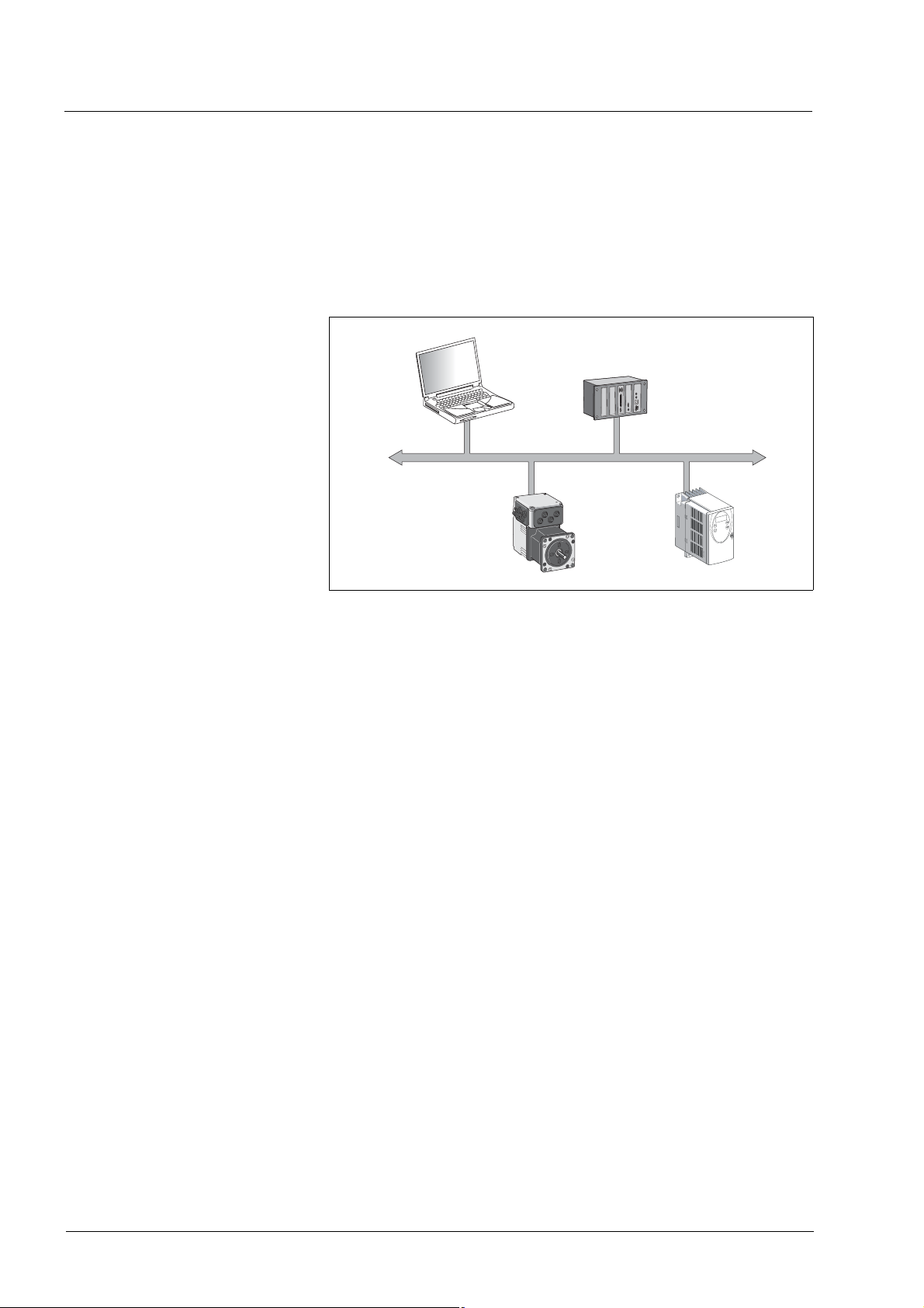
1.3 Fieldbus devices networked via CAN bus
Different fieldbus devices can be operated in the same fieldbus segment. The CANopen bus provides a common basis for interchanging
commands and data between the product described and other network
devices.
Figure 1.1 Fieldbus devices in the network
1.4 Operating modes and functions in fieldbus mode
This manual only describes the protocol for the slave. See the chapters
"Operation" and "Parameters" for descriptions of the operating modes,
functions and all parameters of the slave:
Operating modes • Profile Velocity
• Profile position
•Homing
•Jog
Functions • Definition of direction of rotation
• Motion profile generation
•Quick Stop
• Fast position capture
Settings The following settings can be made via the fieldbus:
• Reading and writing parameters
• Monitoring the inputs and outputs of the 24 V signal interface
• Activating diagnostics and fault monitoring functions
Fieldbus mode
10 Fieldbus interface
0198441113586, V2.01, 11.2008

IL•1F CANopen DS301 1 Introduction
1.5 Documentation and literature references
Manuals In addition to this fieldbus manual, the following manuals also belongs to
the product:
• Product manual, describes the technical data, installation, commissioning and all operating modes and functions.
CAN users and manufacturers
organization
CANopen standards • CiA Standard 301 (DS301)
Literature Controller Area Network
CiA - CAN in Automation
Am Weichselgarten 26
D-91058 Erlangen
http://www.can-cia.org/
CANopen application layer and communication profile
V4.02, February 2002
• CiA Standard 402 (DSP402)
Device profile for drives and motion control
V2.0, July 2002
• ISO/DIS 11898: Controller Area Network (CAN) for high speed
communication;1993
• EN 50325-4: Industrial communications subsystem based on
ISO 11898 for controller device interfaces (CANopen); 2002
Konrad Etschberger, Carl Hanser Verlag
ISBN 3-446-19431-2
0198441113586, V2.01, 11.2008
Fieldbus interface 11

1 Introduction IL•1F CANopen DS301
12 Fieldbus interface
0198441113586, V2.01, 11.2008

IL•1F CANopen DS301 2 Before you begin - safety information
2 Before you begin - safety information
The information provided in this manual supplements the product manual. Carefully read the product manual before you begin.
0198441113586, V2.01, 11.2008
Fieldbus interface 13

2 Before you begin - safety information IL•1F CANopen DS301
14 Fieldbus interface
0198441113586, V2.01, 11.2008
IL•1F CANopen DS301 3 Basics
3Basics
3.1 CANopen technology
3.1.1 CANopen description language
CANopen is a device- and manufacturer-independent description language for communication via the CAN bus. CANopen provides a common basis for interchanging commands and data between CAN bus
devices.
3.1.2 Communication layers
CANopen uses the CAN bus technology for data communication.
CANopen is based on the basic network services for data communication as per the ISO-OSI model model. 3 layers enable data communication via the CAN bus.
• Physical Layer
• Data Link Layer
• Application Layer
device communication
application Layer
data Link Layer
physical Layer
fielb bus communication
CAN-Bus
Figure 3.1 CANopen layer model
Physical Layer The physical layer defines the electrical properties of the CAN bus such
as connectors, cable length and cable properties such as bit-coding and
bit-timing.
Data Link Layer The data link layer connects the network devices. It assigns priorities to
individual data packets and monitors and corrects errors.
Application Layer The application layer uses communication objects (COB) to exchange
data between the various devices. Communication objects are elementary components for creating a CANopen application.
0198441113586, V2.01, 11.2008
Fieldbus interface 15
3 Basics IL•1F CANopen DS301
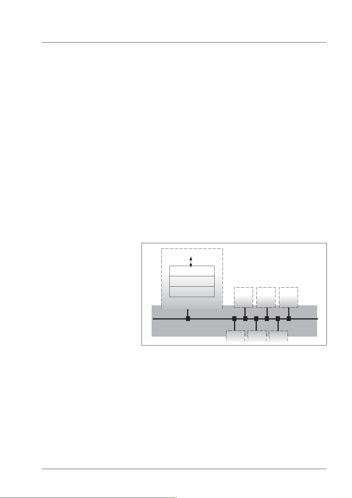
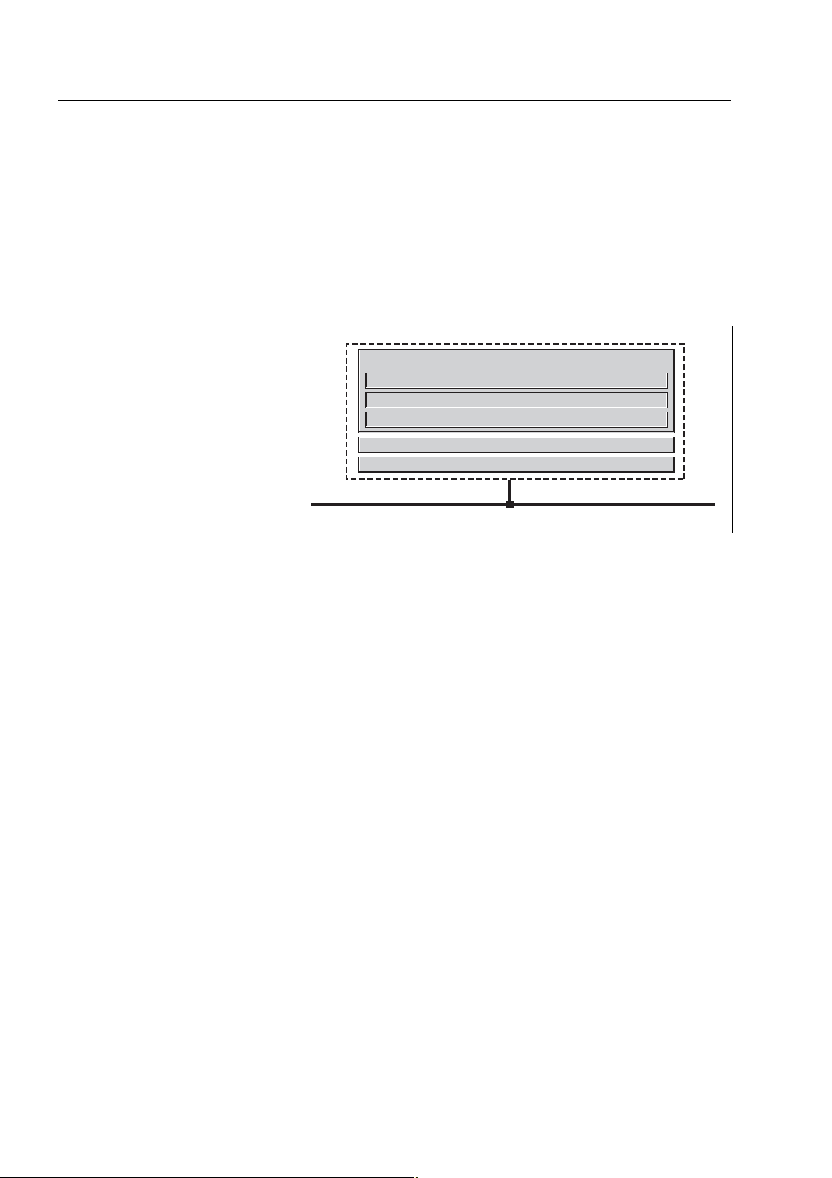
3.1.3 Objects
All processes under CANopen are executed via objects. Objects carry
out different tasks; they act as communication objects for data transport
to the fieldbus, control the process of establishing a connection or monitor the network devices. If objects are directly linked to the device (device-specific objects), the device functions can be used and changed via
these objects.
Object dictionary The object dictionary of each network device allows for communication
between the devices. Other devices find all objects with which they can
communicate in this dictionary.
CANopen
Communication
Process data
objects (PDO)
Service data
objects (SDO)
SYNC, EMCY
Network
management NMT
CAN-Bus
Object
directory
1000
h
3000
h
6000
h
FFFF
h
Device
functions
Application
Device profile
Specific functions
Powe r
amplifier
Motor
Figure 3.2 Device model with object dictionary
Objects for describing the data types and executing the communication
tasks and device functions under CANopen are included in the object
dictionary.
Object index Every object is addressed by means of a 16 bit index, which is repre-
sented as a four-digit hexadecimal number. The objects are arranged in
groups in the object dictionary.
Index (hex) Object groups Supported
by the drive
0000
h
0001
-009FhStatic and complex data types No
h
Reserved No
00A0h-0FFFhReserved No
1000h-1FFFhCommunication profile, standardized in DS 301 Yes
2000
-5FFFhManufacturer-specific device profiles Yes
h
6000h-9FFFhStandardized device profiles, e.g. in DSP 402 No
-FFFFhReserved No
A000
h
Table 3.1 Object index
See page 79, 8.2 "Objects of the product" for a list of the CANopen objects.
Object group data types Data types are used so that the messages that are transmitted via the
network as bit streams have the same meaning for the transmitting and
16 Fieldbus interface
0198441113586, V2.01, 11.2008

IL•1F CANopen DS301 3 Basics
receiving devices. Data types are declared by means of the objects of
the data types.
Object groups of the profiles CANopen objects carry out various tasks in fieldbus mode. Profiles
group the objects by tasks.
0198441113586, V2.01, 11.2008
Fieldbus interface 17
3 Basics IL•1F CANopen DS301
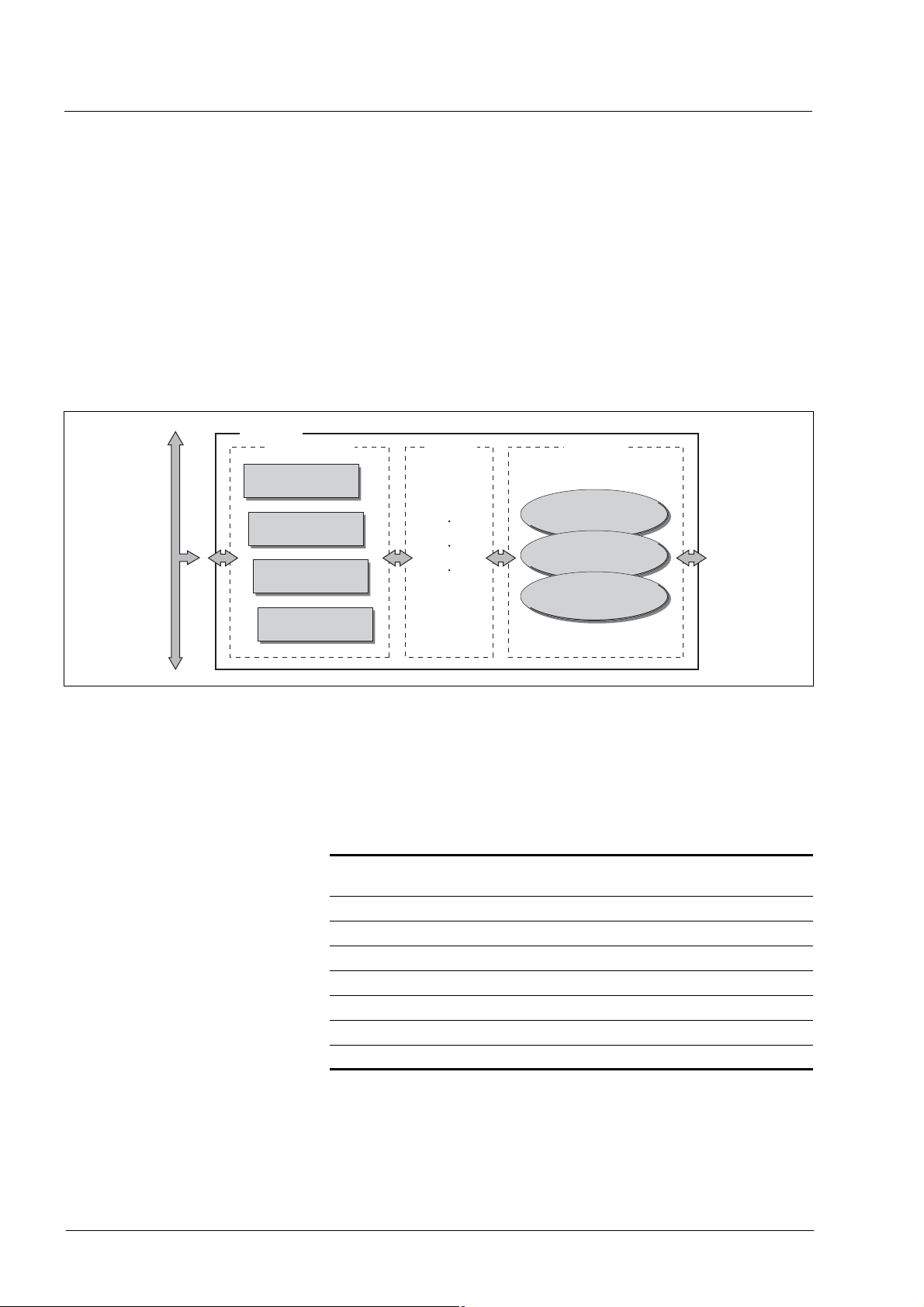
3.1.4 CANopen profiles
Standardized profiles Standardized profiles describe objects that are used with different de-
vices without additional configuration. The users and manufacturers organization CAN in Automation has standardized various profiles. These
include:
• DS301 communication profile
• DSP402 device profile
Application Layer
Application
Device Profile for Drives and Motion Control (CiA DSP 402)
CANopen Communication Profile (CiA DS 301)
Data Link Layer
Physical Layer
CAN-Bus
Figure 3.3 CANopen reference model
DS301 communication profile The DS301 communication profile is the interface between device pro-
files and CAN bus. It was specified in 1995 under the name DS301 and
defines uniform standards for common data exchange between different
device types under CANopen.
The objects of the communication profile in the device carry out the
tasks of data exchange and parameter exchange with other network devices and initialize, control and monitor the device in the network.
Objects of the communication profile are:
• Process Data Objects = PDO
• Service Data Objects = SDO
• Objects with special functions for synchronization SYNC and for
error messages and error response EMCY
• Network management NMT objects for initialization, error monitoring and device status monitoring.
DSP402 device profile The DSP402 device profile describes standardized objects for position-
ing, monitoring and settings of drives. The tasks of the objects include:
• Device monitoring and status monitoring (Device Control)
• Standardized parameterization
• Changing, monitoring and execution of operating modes
IMPORTANT: The product does not support the CiA 402 device profile.
Vendor-specific profiles The basic functions of a device can be used with objects of standardized
device profiles standardized. Only vendor-specific device profiles offer
the complete range of functions. The objects with which the special functions of a device can be used under CANopen are defined in these vendor-specific device profiles.
18 Fieldbus interface
0198441113586, V2.01, 11.2008

IL•1F CANopen DS301 3 Basics
3.2 Communication profile
CANopen manages communication between the network devices with
object dictionaries and objects. A network device can use process data
objects (PDO) and service data objects (SDO) to request the object data
from the object dictionary of another device and, if permissible, write
back modified values.
The following can be done by accessing the objects of the network devices
• Exchange parameter values
• Start motion functions of individual CAN bus devices
• Request status information
3.2.1 Object dictionary
Each CANopen device manages an object dictionary which contains all
objects for communication.
Index, subindex The objects are addressed in the object dictionary via a 16 bit index.
One or more 8 bit subindex entries for each object specify individual data
fields in the object. Index and subindex are shown in hexadecimal notation with a subscript "
".
h
The following example shows the index entries and subindex entries for
the object receive PDO4 mapping, 1603
Index Subindex Object Meaning
1603
1603
1603
1603
Table 3.2 Examples of index and subindex entries
00
h
h
01
h
h
02
h
h
03
h
h
Number of elements Number of subindexes
1st mapped object
R_PDO4
2nd mapped object
R_PDO4
3rd mapped object
R_PDO4
for mapping in R_PDO4.
h
First object for mapping in
R_PDO4
Second object for mapping
in R_PDO4
Third object for mapping in
R_PDO4
0198441113586, V2.01, 11.2008
Fieldbus interface 19

3 Basics IL•1F CANopen DS301
Structure of object dictionary The objects in the object dictionary are sorted by index values. Table 3.3
shows the index ranges of the object dictionary according to the CANopen specifications.
Index range
(hex)
0000
h
0001h-001FhStatic data types No
0020h-003FhComplex data types No
0040
-005FhManufacturer-specific data types No
h
0060h-007FhStatic data types for the device profiles No
0080h-009FhComplex data types for the device profiles No
00A0
-0FFFhReserved No
h
1000h-1FFFhCommunication profile Yes
2000h-5FFFhManufacturer-specific profiles Yes
6000
-9FFFhStandardized device profiles No
h
A000h-FFFFhReserved No
Table 3.3 Index ranges of the object dictionary
Object groups Supported
by the drive
Reserved No
Object descriptions inthe manual For CANopen programming of a product, the following object groups are
described in detail:
• 1xxx
• 3xxx
objects: Communication objects in this chapter
h
objects: Manufacturer-specific objects to the extent they are
h
required for controlling the product
All operating modes and functions of the product are controlled by
means of manufacturer-specific objects. These functions and objects
are described in the device documentation.
The manufacturer-specific objects are stored in the index range starting
at 3000
documentation, it is sufficient to add 3000
. To derive the CAN index from the indexes given in the device
h
.
h
Example: The control word for a state transition has the index 28 and the subindex
1. In the CAN protocol, this results in the index 301C
28
]) and the subindex 1.
d
(3000h + 1Ch[=
h
20 Fieldbus interface
0198441113586, V2.01, 11.2008

IL•1F CANopen DS301 3 Basics
3.2.2 Communication objects
Overview The communication objects are standardized with the DS301 CANopen
communication profile. The objects can be classified into 4 groups according to their tasks.
PDO
T_PDO1 R_PDO1
T_PDO2 R_PDO2
T_PDO3 R_PDO3
T_PDO4 R_PDO4
Communication
SDO
T_SDO
R_SDO
Figure 3.4 Communication objects; the following applies to the perspective
of the network device: T_..: "Transmit", R_..: "Receive"
objects
Special objects
SYNC
EMCY
Network
management
NMT Services
NMT Node guarding
NMT Heartbeat
• PDOs (process data objects) for real-time transmission of process
data
• SDOs (service data object) for read and write access to the object
dictionary
• Objects for controlling CAN messages:
– SYNC object (synchronization object) for synchronization of net-
work devices
– EMCY object (emergency object), for signaling errors of a device
or its peripherals.
• Network management services:
– NMT services for initialization and network control (NMT: net-
work management)
– NMT Node Guarding for monitoring the network devices
– NMT Heartbeat for monitoring the network devices
0198441113586, V2.01, 11.2008
Fieldbus interface 21
3 Basics IL•1F CANopen DS301
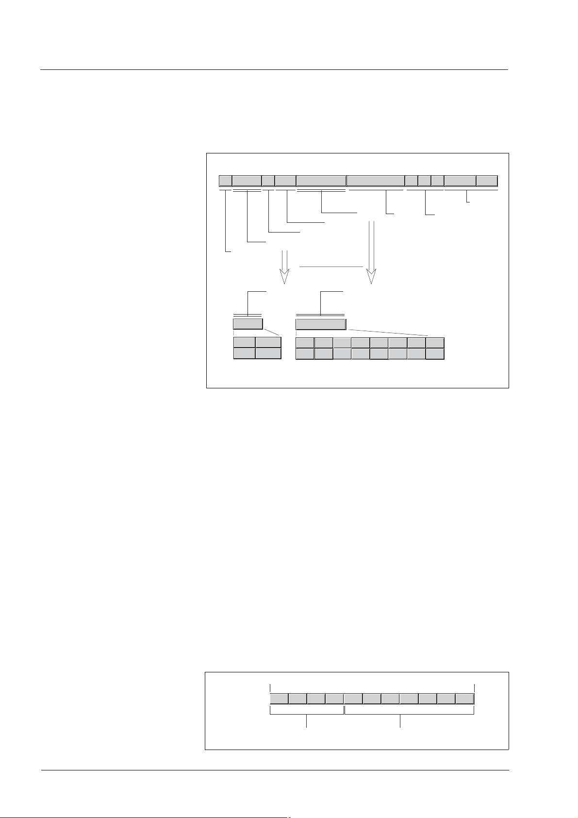
CAN message Data is exchanged via the CAN bus in the form of CAN messages. A
CAN message transmits the communication object and a variety of administration and control information.
CAN message
111 1 111 7
Data
Control
RTR-Bit
Identifier
Start-Bit
CRC
Acknowledge
>=36160..8 Byte
End-Bits
COB-ID
11 Bit
7 Bit4 Bit
CANopen message (simplified)
0..8 Byte
data carrier
1 2 3 4 5 6 70
Figure 3.5 CAN message and simplified representation of CANopen mes-
sage
CANopen message For work with CANopen objects and for data exchange, the CAN mes-
sage can be represented in simplified form because most of the bits are
used for error correction. These bits are automatically removed from the
receive message by the data link layer of the OSI model, and added to
a message before it is transmitted.
The two bit fields "Identifier" and "Data" form the simplified CANopen
message. The "Identifier" corresponds to the "COB ID" and the "Data"
field to the data frame (maximum length 8 bytes) of a CANopen message.
COB ID The COB ID (Communication OBject Identifier) has 2 tasks as far as
controlling communication objects is concerned:
• Bus arbitration: Specification of transmission priorities
• Identification of communication objects
An 11 bit COB identifier as per the CAN 3.0A specification is defined for
CAN communication; it comprises 2 parts
• Function code, 4 bits
• Node address (node ID), 7 bits.
Bit:10 0
1
COB-ID
2 3 4 1 2 3 4 5 6 7
Function code
0...15
Node-ID
0...127
Figure 3.6 COB ID with function code and node address
22 Fieldbus interface
0198441113586, V2.01, 11.2008

IL•1F CANopen DS301 3 Basics
COB IDs of the communication
objects
The following table shows the COB IDs of all communication objects
with the factory settings. The column "Index of object parameters"
shows the index of special objects with which the settings of the communication objects can be read or modified via an SDO.
Communication object Function
code
NMT Start/Stop Service 0 0 0 0 0 0 0 0 0 0 0 0 (0
SYNC object 0 0 0 1 0 0 0 0 0 0 0 128 (80h) 1005h....1007
EMCY object 0 0 0 1 x x x x x x x 128 (80h) + node ID 1014h, 1015
T_PDO1
R_PDO1
T_PDO2
R_PDO2
T_PDO3
R_PDO3
1)
1)
1)
1)
1)
1)
0 0 1 1 x x x x x x x 384 (180h) + node ID 1800
0 1 0 0 x x x x x x x 512 (200h) + node ID 1400
0 1 0 1 x x x x x x x 640 (280h) + node ID 1801
0 1 1 0 x x x x x x x 768 (300h) + node ID 1401
0 1 1 1 x x x x x x x 896 (380h) + node ID 1802
1 0 0 0 x x x x x x x 1024 (400h) + node ID 1402
T_PDO4 1 0 0 1 x x x x x x x 1152 (480h) + node ID 1803
R_PDO4 1 0 1 0 x x x x x x x 1280 (500h) + node ID 1403
T_SDO 1 0 1 1 x x x x x x x 1408 (580h) + node ID R_SDO 1 1 0 0 x x x x x x x 1536 (600
NMT error control 1 1 1 0 x x x x x x x 1792 (700h) + node ID
LMT Services
NMT Identify Service
DBT Services
NMT Services
1) Not supported by the device
1)
1)
1)
1 1 1 1 1 1 0 0 1 0 x 2020 (7E4h), 2021 (7E5h)
1)
1 1 1 1 1 1 0 0 1 1 0 2022 (7E6h)
1 1 1 1 1 1 0 0 x x x 2023 (7E7h), 2024 (7F8h)
1 1 1 1 1 1 0 1 0 0 x 2025 (7E9h), 2026 (7EAh)
Node address,
node ID [1...127]
COB ID decimal (hexadecimal) Index of object
parameters
)-
h
h
h
h
h
h
h
h
h
) + node ID -
h
h
h
Table 3.4 COB IDs of all communication objects
COB IDs of PDOs can be changed as required. The
assignment pattern for COB IDs only specifies a basic
setting.
Function code The function code classifies the communication objects. Since the bits
of the function code in the COB ID are more significant, the function
code simultaneously controls the transmission priorities: Objects with a
lower function code are transmitted with higher priority. For example, an
object with function code "1" is transmitted prior to an object with function code "3" in the case of simultaneous bus access.
Node address Every network device is configured before it is operated on the network.
The device is assigned a 7 bit node address (node ID) between 1 (01
and 127 (7F
). The device address "0" is reserved for "broadcast" trans-
h
missions which are used to send messages to all devices simultaneously.
0198441113586, V2.01, 11.2008
Fieldbus interface 23
)
h
3 Basics IL•1F CANopen DS301
Example Selection of a COB ID
For a device with the node address 5, the COB ID of the communication
object T_PDO1 is:
384+node ID = 384 (180
Data frame The data frame of the CANopen message can hold up to 8 bytes of data.
In addition to the data frame for SDOs and PDOs, special frame types
are specified in the CANopen profile:
• Error data frame
• Remote data frame for requesting a message
The data frames contain the respective communication objects.
3.2.3 Communication relationships
CANopen uses 3 relationships for communication between network devices:
• Master-slave relationship
• Client-server relationship
• Producer-consumer relationship
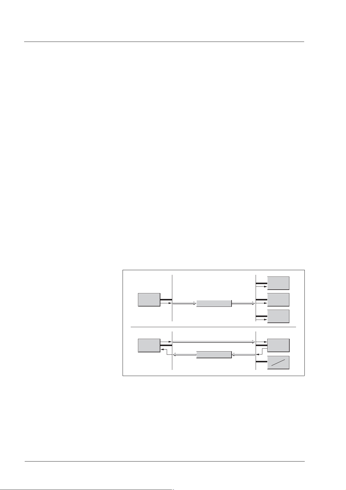
Master-slave relationship A network master controls the message traffic. A slave only responds
when it is addressed by the master.
The master-slave relationship is used with network management objects for a controlled network start and to monitor the connection of devices.
) + 5 = 389 (185h).
h
Slave
Master
Master
Figure 3.7 Master - slave relationships
data
request
data
Slave
Slave
Slave
Messages can be interchanged with and without confirmation. If the
master sends an unconfirmed CAN message, it can be received by a
single or by several slaves or by no slave.
To confirm the message, the master requests a message from a specific
slave, which then responds with the desired data.
24 Fieldbus interface
0198441113586, V2.01, 11.2008
IL•1F CANopen DS301 3 Basics
Client-server relationship A client-server relationship is established between 2 devices. The
"server" is the device whose object dictionary is used during data exchange. The "client" addresses and starts the exchange of messages
and waits for a confirmation from the server.
A client-server relationship with SDOs is used to send configuration data
and long messages.
Client
Figure 3.8 Client-server relationship
data
data
Server
The client addresses and sends a CAN message to a server. The server
evaluates the message and sends the response data as an acknowledgement.
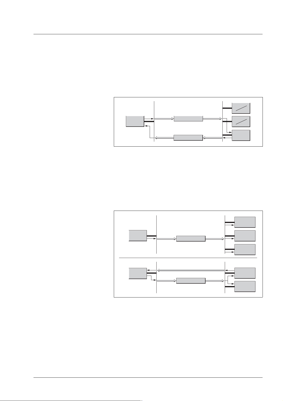
Producer-consumer relationship The producer-consumer relationship is used for exchanging messages
with process data, because this relationship enables fast data exchange
without administration data.
A "Producer" sends data, a "Consumer" receives data.
Consumer
Producer
data
Consumer
Consumer
request
Producer
data
Figure 3.9 Producer-consumer relationships
Consumer
Consumer
The producer sends a message that can be received by one or more
network devices. The producer does not receive an acknowledgement
to the effect that the message was received. The message transmission
can be triggered
• by an internal event, e.g. "target position reached"
• by the synchronization object SYNC
• a request of a consumer
For details on the function of the producer-consumer relationship and on
requesting messages see chapter 3.4 "Process data communication".
0198441113586, V2.01, 11.2008
Fieldbus interface 25
3 Basics IL•1F CANopen DS301
3.3 Service data communication
3.3.1 Overview
Service Data Object(SDO: Service Data Object) can be used to access
the entries of an object dictionary via index and subindex. The values of
the objects can be read and, if permissible, also be changed.
Every network device has at least one server SDO to be able to respond
to read and write requests from a different device. A client SDO is only
required to request SDO messages from the object dictionary of a different device or to change them there.
The T_SDO of an SDO client is used to send the request for data exchange; the R_SDO is used to receive. The data frame of an SDO consist of 8 bytes.
SDOs have a higher COB ID than PDOs and therefore are sent over the
CAN bus at a lower priority.
3.3.2 SDO data exchange
A service data object (SDO) sends parameter data between two devices. The data exchange conforms to the client-server relationship. The
server is the device to whose object dictionary an SDO message refers.
Client
R_SDO T_SDO
(request)
COB-ID data
CAN
Figure 3.10 SDO message exchange with request and response
COB-ID
data
(response)
T_SDO
R_SDO
Server
Message types Client-server communication is triggered by the client to send parameter
values to the server or to get them from the server. In both cases, the client starts the communication with a request and receives a response
from the server.
26 Fieldbus interface
0198441113586, V2.01, 11.2008
IL•1F CANopen DS301 3 Basics
3.3.3 SDO message
Put simply, an SDO message consists of the COB ID and the SDO data
frame, in which up to 4 bytes of data can be sent. Longer data sequences are distributed over multiple SDO messages with a special protocol.
The device sends SDOs of up to 4 bytes data length (data). Greater
amounts of data such as 8 byte values of the data type "Visible String 8"
can be distributed over multiple SDOs and are transmitted successively
in 7 byte blocks.
Example The following illustration shows an example of an SDO message.
SDO
581
COB-ID
(581h)
1 2 3 4 5 6 7
0
00
43 10 00 01 0292 00
Data
Subindex
Index
Command Code
Figure 3.11 SDO message, example
COB ID and data frame R_SDO and T_SDO have different COB IDs.
The data frame of an SDO messages consists of:
• Command code (ccd) in which the SDO message type and the data
length of the transmitted value are encrypted
• Index and subindex which point to the object whose data is transported with the SDO message
• Data of up to 4 bytes
Evaluation of numeric values Index and data are transmitted left-aligned in Intel format. If the SDO
contains numerical values of more than 1 byte in length, the data must
be rearranged byte-by-byte before and after a transmission.
581
Index:
1 2 3 4 5 6 7
0
00
43 10 00 01 0292 00
Data:
Hex:
10 00
h
00 02 01 92
h
Figure 3.12 Rearranging numeric values greater than 1 byte
0198441113586, V2.01, 11.2008
Fieldbus interface 27
3 Basics IL•1F CANopen DS301
3.3.4 Reading and writing data
Writing data The client starts a write request by sending index, subindex, data length
and value.
The server sends a confirmation indicating whether the data was correctly processed. The confirmation contains the same index and
subindex, but no data.
Client
write request
COB-ID
COB-ID
ccd=
ccd
60h
ccd=
ccd=
ccd=
ccd=
Idx
1
ccd
23h
27h
2Bh
2Fh
2
Idx
2 3 4 5 6 70
1
Idx
Idx
2 3 4 5 6 70
Sidx
1
Sidx
2
1
data
data
data
data
data
data
write response
Server
Figure 3.13 Writing parameter values
Unused bytes in the data field are shown with a slash in the graphic. The
content of these data fields is not defined.
ccd coding The table below shows the command code for writing parameter values.
It depends on the message type and the transmitted data length.
Message type Data length used
4 bytes 3 bytes 2 bytes 1 byte
Write request 23
Write response 60
Error response 80
27
h
60
h
80
h
2B
h
60
h
80
h
2F
h
60
h
80
h
Transmitting param-
h
eters
Confirmation
h
Error
h
Table 3.5 Command code for writing parameter values
28 Fieldbus interface
0198441113586, V2.01, 11.2008
IL•1F CANopen DS301 3 Basics
Reading data The client starts a read request by sending the index and subindex that
point to the object or the object value whose value it wants to read.
The server confirms the request by sending the desired data. The SDO
response contains the same index and subindex. The length of the response data is specified in the command code "ccd".
Client
read request
COB-ID
ccd=
ccd=
ccd=
ccd=
COB-ID
ccd
43h
47h
4Bh
4Fh
ccd=
Idx
2 3 4 5 6 70
1
ccd
40h
1
Idx
2
Idx
Idx
2 3 4 5 6 70
Sidx
1
Sidx
2
1
data
data
data
data
read response
data
data
Server
Figure 3.14 Reading a parameter value
Unused bytes in the data field are shown with a slash in the graphic. The
content of these data fields is not defined.
ccd coding The table below shows the command code for transmitting a read value.
It depends on the message type and the transmitted data length.
Message type Data length used
4
1 byte
bytes3 bytes2 bytes
read request 40
Read response 43
Error response 80
40
h
47
h
80
h
40
h
4B
h
80
h
40
h
4F
h
80
h
Request read value
h
Return read value
h
Error
h
Table 3.6 Command code for transmitting a read value
0198441113586, V2.01, 11.2008
Fieldbus interface 29

3 Basics IL•1F CANopen DS301
Error response If a message could not be evaluated without errors, the server sends an
error message. For details on the evaluation of the error message see
chapter 7 "Diagnostics and troubleshooting".
Client
2 3 4 5 6 70
1
Idx
COB-ID
ccd:
ccd
80
Idx
Sidx
1
2
data
Figure 3.15 Response with error message (error response)
Server
error response
Byte 4-7
error code
30 Fieldbus interface
0198441113586, V2.01, 11.2008

IL•1F CANopen DS301 3 Basics
3.4 Process data communication
3.4.1 Overview
This chapter describes the flow of information from the
perspective of your product in compliance with CiA
standard DS301. The designation "receive" relates to a
flow of data from the master to the product, while "transmit"
represents a flow of data from the product to the master.
Process data objects (PDO: Process Data Object) are used for real-time
data exchange of process data such as actual and reference or operating state of the device. Transmission is very fast because the data is sent
without additional administration data and a response from the recipient
is not required.
The flexible data length of a PDO message also increases the data
throughput. A PDO message can transmit up to 8 bytes of data. If only
2 bytes are assigned, only 2 data bytes are sent.
The length of a PDO message and the assignment of the data fields are
specified by PDO mapping. For more information see chapter 3.4.2.1
"Dynamic and static PDO mapping".
PDO messages can be exchanged between devices that generate or
process process data.
One PDO each is available for sending and receiving a PDO message:
• T_PDO to transmit the PDO message (T: "Transmit"),
• R_PDO to receive data (R: "Receive").
0198441113586, V2.01, 11.2008
Fieldbus interface 31

3 Basics IL•1F CANopen DS301
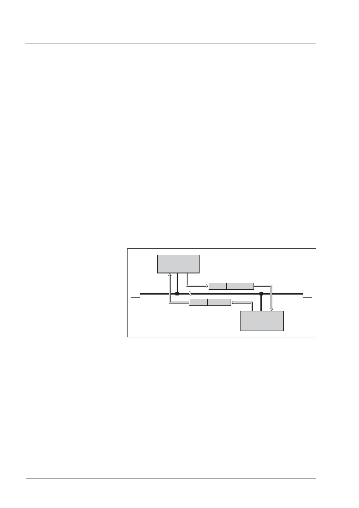
3.4.2 PDO data exchange
PDO Consumer
COB-ID Data
T_PDO
PDO Producer
Figure 3.16 PDO data exchange
R_PDO
PDO Consumer
PDO Consumer
R_PDO
CAN
R_PDO
Data exchange with PDOs follows to the producer-consumer relationship and can be triggered in 3 ways
• Synchronized
• Event-driven, asynchronous
• On request of a consumer, asynchronous
The SYNC object controls synchronized data processing. Synchronous
PDO messages are transmitted immediately like the standard PDO
messages, but are only evaluated on the next SYNC. For example, several drives can be started simultaneously via synchronized data exchange.
The device immediately evaluates PDO messages that are called on request or in an event-driven way.
The transmission type can be specified separately for each PDO with
subindex 02
(transmission type) of the PDO communication parameter.
h
The objects are listed in 8 "Object directory".
Event-driven The "event" is a change of the PDO data. In this mode, the data is im-
mediately transmitted after a change. Please note that in the case of, for
example, a positioning movement, the actual position changes constantly so that a large number of PDOs is transmitted. There are two
ways to avoid such a large number of PDOs:
• A) You can set an "Inhibit Timer" (object 1803
subindex 3). The
h
PDO is not sent until after this inhibit time has passed.
• B) By using a bit mask, you can limit the check for changes
(=event). See section "Bit mask for T_PDO4" for a description.
A further possibility of "creating" an event consists of activating an
"Event Timer" (object 1803
subindex 5). You activate this counter by en-
h
tering a value not equal to zero. When this counter is reached, this represents an additional event. This means that the PDO is transmitted
when a value changes or when the counter event occurs.
Synchronized In the case of this transmission mode, a PDO is transmitted in relation
to a SYNC object. See 3.5 "Synchronization" for a detailed description.
32 Fieldbus interface
0198441113586, V2.01, 11.2008

IL•1F CANopen DS301 3 Basics
Remotely requested Transmission of an asynchronous PDO is triggered when an external re-
quest is received. Such a "Remote Request" is represented by a special
bit in the CAN transmission frame; it has the same COB ID (communication object identifier) as the requested communication object.
An overview of the individual transmission types can be found in the object dictionary, PDO parameters.
Bit mask for T_PDO4 A bit mask can be defined for the objects CAN.pdo4msk1 (30:9) and
CAN.pdo4msk2 (30:10) in T_PDO4. All bit positions containing a "zero"
are then no longer considered in the checks for changes (=event). This
allows you, for example, to limit checks to changes of the driveStat information.
NameIdx:Sub
dec. (hex.)
30:9 (1E:09h) The default value 4294967295 corresponds to 0xFFFFFFFF. UINT32 -
30:10
(1E:0Ah)
MeaningBit assignment Data type UnitDe-
See object pdo4msk1 for a description. UINT32 -0 R/W/-
Table 3.7 Parameters for the CAN bus
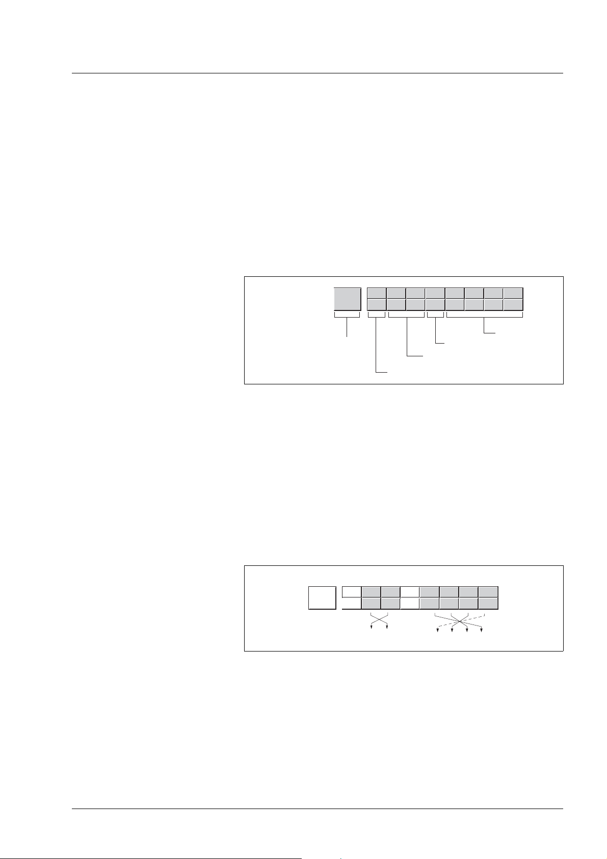
Example In this example, setting the object CAN.pdo4msk2 to zero keeps modi-
fications to the current position from triggering an event.
pdo4msk2
pdo4msk1
FFhFFh FFhFFh
ByteT_PDO4
21 43 65 87
driveStat
00h00h 00h00h
reserved
modeStat
fault (dez.)
429496729
5
actual Position
R/W/
rem. Info
R/W/-
Figure 3.17 Setting the object CAN.pdo4msk2 to zero
0198441113586, V2.01, 11.2008
Fieldbus interface 33

3 Basics IL•1F CANopen DS301
Requesting process data One or more network devices with consumer function can request PDO
messages from a producer. The producer is identified by the COB ID of
the request and responds with the requested PDO.
RTR
Consumer
COB-Id
COB-Id
Figure 3.18 Requesting a message with RTR = 1
1
0
Daten
Producer
The RTR bit (RTR: Remote Transmission Request) of a CAN message
is used to detect a request. The COB ID remains the same for both messages:RTR = 0: transmission of dataRTR = 1: request for data.
Setting RTR request You can set for each PDO separately whether it responds to RTR re-
quests. This is switched on or off via subindex 01, bit 30
Subindex 02
(transmission type) of the objects defines the transmis-
h
of each PDO.
h
sion type. The PDO only responds to a request via bit RTR if RTR transmission is enabled for a PDO. The subindex values for the RTR bit are:
Objects 1403h, 1803h subindex 02h,
"transmission type"
252 RTR active, synchronous
253 RTR active, asynchronous
Table 3.8 Subindexes for using the bit
Meaning
An overview of all values for the subindex 02h can be found in the object
dictionary for the corresponding object.
The product cannot request PDOs, but it can respond to the request of
PDOs.
3.4.2.1 Dynamic and static PDO mapping
Dynamic PDO mapping The settings for PDO mapping are defined in an assigned communica-
tion object for each PDO. If the PDO mapping settings for a PDO can be
changed, this is referred to as dynamic PDO mapping for the PDO. Dynamic PDO mapping enables flexible combination of different process
data during operation.
Static PDO mapping Static PDO mapping means that all objects are mapped in accordance
with a fixed setting in the corresponding PDO.
Properties of the integrated drive. The integrated drive supports 2 PDOs, the communication objects
T_PDO4 and R_PDO4. These two PDO4 are enabled by default.
These PDOs are mapped statically, i.e. they cannot be configured but
only read. The indexes for the permanently entered objects can be read
from the PDO mapping object range:
•Object 1403
•Object 1603
•Object 1803
•Object 1A03
: receive PDO4 communication parameter
h
: receive PDO4 mapping
h
: transmit PDO4 communication parameter
h
: transmit PDO4 mapping
h
34 Fieldbus interface
0198441113586, V2.01, 11.2008

IL•1F CANopen DS301 3 Basics
3.4.2.2 Receive PDO R_PDO4 (master -> slave)
The master device can execute the following actions via the PDO4 channel to the slave:
• Control the state machine of the slave
– Enable/disable the power stage of the product
– Trigger and reset a "Quick Stop"
– Resetting faults
• Toggle the operating modes
– Profile Position operating mode, absolute and relative
– Profile Velocity operating mode
– Reference movement
– Position setting
• Set reference values
– Reference position
Structure of R_PDO4:
– Reference speed
– Type of reference movement
Byte
Bit
Bit
21 43 65 87
Ref16 -> reference 16 bits - e.g. velocity
modeCtrl
driveCtrl
driveCtrl - 8 Bits
67 45 23 01
00 QR0 QSFR DIEN
Quickstop Release
modeCtrl - 8 Bits
67 45 23 01
MT ACTION 0 MODE
Ref32 -> reference 32 bits - e.g. position
Disable
Enable
Quickstop
Fault Reset
Requested Mode
Action within Mode
Mode Toggle
Figure 3.19 Structure of R_PDO4
0198441113586, V2.01, 11.2008
Fieldbus interface 35

3 Basics IL•1F CANopen DS301
State machine – drivectrl
The state machine is controlled via PDO4 or the SDO object
drivectrl, 28:1, in both cases via bits Bits 0 ... 4.
In PDO mode, a change form 0 to 1 triggers the corresponding function.
In the case of access via SDO, a write access with a set bit value is sufficient, i.e. a change of edge is not required.
Controlling the state machine PDO4Bits 0 ... 4 SDO object drivectrl, 28:1Bits 0 ... 4
Bit 0: Power stage Disable Triggered when 0 changes to 1 Triggered at write access if bit value = 1
Bit 1: Power stage Enable
Bit 2: Quickstop
Bit 3: Fault Reset
Bit 4: Quickstop Release
The value "0" is a special case: If during transmission all bits 0 ... 7 are
"zero", the product interprets this as "Disable" command and disables
the power stage. This applies to both PDO and SDO access.
Handling of errors If requests for controlling the state machine cannot be executed by the
product, the product ignores such request. There is no error response.
36 Fieldbus interface
0198441113586, V2.01, 11.2008

IL•1F CANopen DS301 3 Basics
Operating modes – modeCtrl
In PDO mode, the operating modes are controlled via object modeCtrl.
The master must enter the following values to activate an operating
mode or to change reference values:
• Reference values in fields "Ref16" and "Ref32"
• Select operating mode with modeCtrl, Bits 0 ... 2 (MODE)
• Select action for this operating mode with modeCtrl, bits 4 ... 6
(ACTION)
• Toggle modeCtrl, bit 7 (MT)
The following table shows the possible operating modes and the corresponding reference values:
Mode bits
0... 2
1 (JOG) 0 01h Jog 41:3 Start (as object 41:1) -
2 (REF) 0 02h Position setting 40:3 - Position for posi-
3 (PTP) 0 03h Absolute positioning 35:1 Reference speed Reference posi-
4 (VEL) 0 04h Profile Velocity 36:1 Reference speed -
1) Column corresponds to the value to be entered in byte modeCtrl, but without ModeToggle (bit 7)
2) Column shows Index:Subindex (decimal) of the corressponding operating mode objects modes which are described in more
detail in the device documentation.
Action
bits 4 ...
6
1 12h Reference movement 40:1 Type (as object 40:1) -
1 13h Relative positioning 35:3 Reference speed Reference posi-
2 23h Continue positioning 35:4 Reference speed -
modeCtrl
1)
. Bits 0
... 6
Description Corre-
sponds to
object
Reference value Ref16 Reference
2)
value Ref32
tion setting
tion
tion
0198441113586, V2.01, 11.2008
Fieldbus interface 37

3 Basics IL•1F CANopen DS301
Reference positions are entered in increments, reference speeds in
-1
[min
].
@ WARNING
UNINTENDED OPERATION
• Note that any changes to the values of these parameters are executed by the drive controller immediately on receipt of the data
set.
• Verify that the system is free and ready for movement before
changing these parameters.
Failure to follow these instructions can result in death, serious
injury or equipment damage.
If operating mode, reference position and reference speed are transmitted simultaneously in one PDO, data consistency is required. For this
reason, the product evaluates the operating mode data only if bit 7 was
toggled. Toggling means that a "0 -> 1" or a "1 -> 0" change of edge was
detected.
Bit 7 is mirrored in the response PDO4 from the product so that synchronized operation is possible via PDO4.
Handling of errors Requests for operating mode are triggered by toggling the bit 7 . If these
requests cannot be executed, the product provides an error response as
described in section Transmit PDO4 - Handling of errors.
3.4.2.3 Transmit PDO T_PDO4 (product to master)
With the default product settings, the transmit PDO is sent asynchronously and in an "event-driven" way; an "Inhibit Time" can be set.
The product provides the master with the following information via
PDO4:
• State of state machine
• Errors and warnings
• Active operating mode
• Status of active operating mode
– Operating mode terminated
– Error occurred
– Reference speed or reference position reached
– Actual position
• Slave referenced
• Acknowledgement of operating mode requests
• Status of the 24 V inputs and outputs
38 Fieldbus interface
0198441113586, V2.01, 11.2008

IL•1F CANopen DS301 3 Basics
Structure of T_PDO4:
Byte
Bit
Bit
Bit
21 43 65 87
IO_act, 8 bits
modeStat, 8 bits
driveStat, 16 bits
driveStat
15 14 13 12 --- 8 7 6 5 3 --- 04
x err x_end x_info 0 0 0 0 0 warn Sig_SR FltSig cos0
modeStat
67 45
MEMT 0ref_ok
drive referenced
Mode Error
Mode Toggle
IO_act
67 45 23 01
STO_ASTO_B
23 01
0 mode
actual position (pact), 32 bits
actual operation mode
IO1IO2IO30
IO00
STO_A / STO_B
(PWRR_A / PWRR_B)
Figure 3.20 Structure of T_PDO4
Status word driveStat The information in the status word driveStat corresponds to bits 0
...15 of object Status.driveStat, 28:2.
Contents of information:
• State of state machine
• Warning and error bits
• Status of the current operating mode
0198441113586, V2.01, 11.2008
Fieldbus interface 39

3 Basics IL•1F CANopen DS301
Operating mode modeStat This field corresponds to bits 0 ... 2 of the object Status.xMode_act.
Bits 6 and 7 provide additional information that can be used for synchronized operating mode control via the PDOs.
The field contains the following information:
Bit Name Description
0...2 mode currently set operating mode as in R_PDO4
5 ref_ok Is set if homing of the product by means of a reference movement or position setting was
successful.
6 ME, ModeError Set if a request of the master via R_PDO4 data was rejected by the product.
7 MT, ModeToggle Mirrors bit 7 (Mode Toggle) of R_PDO4
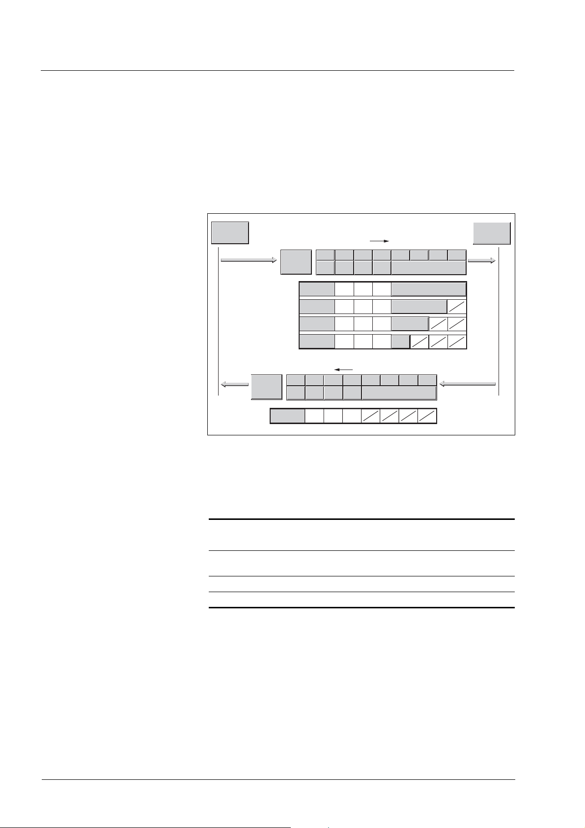
3.4.2.4 Handshake with Mode Toggle Bit
Mode Toggle Synchronized processing is possible with the transmit data modeCtrl,
bit 7 (MT) and the receive data modeStat, bits 6 (ME) and 7 (MT). Synchronized processing means that the master waits for feedback messages from the slave so it can respond appropriately.
Example of positioning The master starts a positioning movement at point in time t
time t
, t2 ..., the master checks the responses from the slave. It waits
1
for the end of the positioning movement by checking the Input Assembly
for bit x_end = 1 (end of positioning).
Master Slave
t
0
t
1
t
2
Mode Toggle
1
Mode Toggle
x_end
2
Figure 3.21 Mode Toggle Handshake
3
(1) Master starts positioning with MT = 1 in byte modeCtrl
(2) Slave signals that positioning is active with MT = 1 in
modeStat and simultaneously with x_end = 0 in driveStat
(4) Slave signals end of positioning with x_end = 1 in
driveStat
. At points in
0
t
3
40 Fieldbus interface
0198441113586, V2.01, 11.2008

IL•1F CANopen DS301 3 Basics
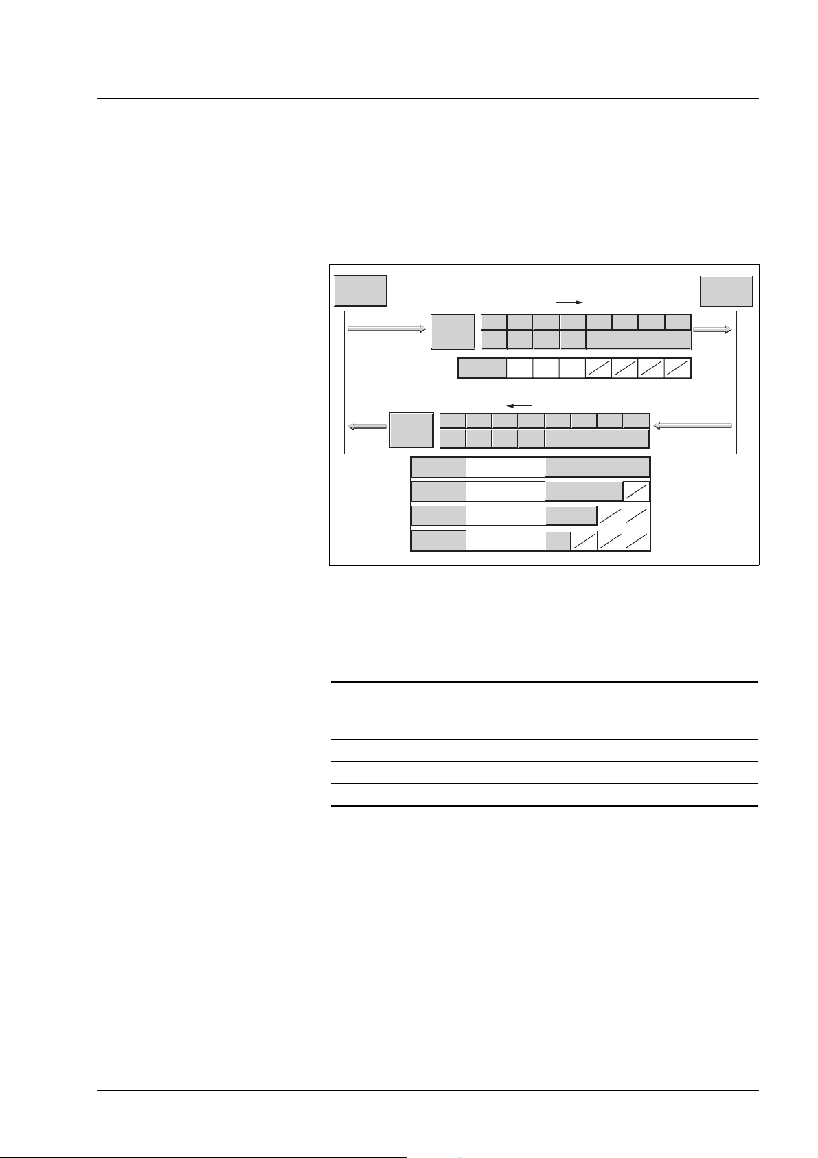
Example of short positioning The master starts a positioning movement that will only take a very short
time. The duration is shorter than the polling cycle of the master. At point
in time t
ter does not know whether the movement is already complete or has not
yet been started. However, it detects this with the MT bit from the slave:
MasterMTSlaveMTSlave
1 0 1 Slave has not yet detected command
1 1 0 Slave has detected command, positioning
1 1 1 Slave signals that positioning is complete
The master may only evaluate data in which the received MT bit is identical to the last bit transmitted by the master.
the movement is already complete. Using bit x_end, the mas-
1
x_end
running
Master Slave
t
0
t
1
t
2
Mode Toggle
1
Mode Toggle
x_end
3
2
Figure 3.22 Mode Toggle Handshake, short movement
(1) Master starts positioning with MT = 1 in byte modeCtrl
(2+3) Slave signals that positioning is active with MT = 1 in
modeStat and simultaneously with x_end = 0 in driveStat
(4) Slave signals end of positioning with x_end = 1 in
driveStat
0198441113586, V2.01, 11.2008
Fieldbus interface 41

3 Basics IL•1F CANopen DS301
Handling of errors If the master toggles bit 7 (MT), this is interpreted by the slave as a re-
quest to start an operating mode or to change data of the current operating mode. If the request cannot be processed, the active operating
mode is not changed and the slave sets bit 6 in modeStat (ME =
ModeError).
The active operating mode is not changed and there is no state transition.
Bit 6 (ME) remains set until the master toggles bit 7 (MT) in modeCtrl
again, thus triggering a new command.
The master can read the corresponding error code by a read access to
parameter ModeError.
Possible reasons for a failure of the operating mode request:
• Reference values outside the value range
• Change of the operating mode during processing (impossible)
• Invalid operating mode requested
• The device is not in state 6 (Operation Enable) of the state
machine.
For more information see the product manual.
42 Fieldbus interface
0198441113586, V2.01, 11.2008

IL•1F CANopen DS301 3 Basics
3.4.2.5 Emergency service
The Emergency Service signals internal device errors via the CAN bus.
The error is sent to all network devices with an EMCY object according to
the "Consumer-Producer" relationship.
EMCY-Consumer
COB-ID
EMCY-Producer
Figure 3.23 Error message with the EMCY object
data
EMCY message Causes of an EMCY comprise:
• asynchronous errors, error code = 1000
device error, the product switches to fault state in accordance with
the device's state machine. At the same time, the product transmits
an EMCY message with error register and error code.
• PDO4 error during operating mode control, error code = 8200
the request for an operating mode via PDO4 fails, the product also
sends an EMCY message.
• CAN communication error, error code = 8100
1 2 3 4 5 6 7
81
0
22
12 00 00 00 0000 00
EMCY-Consumer
CAN
EMCY-Consumer
In the case of an internal
h
h
h
If
Manufacturer specific error field
Error register
Error code
COB-ID (80h+ Node-ID)
Figure 3.24 EMCY message
Error code
• Bytes 0, 1 (error code): CANopen error codeThis value is 1000,
8200
or 8100h, depending on the cause of the error.
h
• Byte 2: Error registerThe value is also stored in the object Error register, 1001
.
h
• Byte 3 (Manufacturer-Specific Error Field):Manufacturer-specific
error, error class
Bytes 6 and 7 are 0. Bytes 4,5 contain a manufacturer-specific error
number.See the product manual for a list of the error numbers.
COB ID The COB ID for every device on the network supporting an EMCY object
is determined on the basis of the node address:
COB ID = Function code of EMCY object, 80
0198441113586, V2.01, 11.2008
+ Node-Id
h
Fieldbus interface 43
0 1
12 22
22 12
h

3 Basics IL•1F CANopen DS301
3.5 Synchronization
The synchronization object SYNC controls the synchronous exchange
of messages between network devices for purposes such as the simultaneous start of multiple drives.
The data exchange conforms to the producer-consumer relationship.
The SYNC object is transmitted to all devices by a network device and
can be evaluated by all devices that support synchronous PDOs.
COB-ID
SYNC- Producer
Figure 3.25 SYNC message
SYNC-Consumer
SYNC-Consumer
SYNC-Consumer
CAN
Time values for synchronization Two time values define the behavior of synchronous data transmission:
• The cycle time specifies the time intervals between 2 SYNC mes-
sages. It is set with the object Communication cycle
period(1006
).
h
• The synchronous time window specifies the time span during which
the synchronous PDO messages must be received and trnasmitted.
The time window is defined with the object Synchronous window
length (1007
SYNC
).
h
T_PDO (status)
R_PDO (controller)
SYNC
CAN-Bus
synchronous
time window
cycle time
Figure 3.26 Synchronization times
process
R_PDO data
Synchronous data transmission From the perspective of a SYNC recipient, in one time window the status
data is transmitted first in a T_PDO, then new control data is received via
an R_PDO. However, the control data is only processed when the next
SYNC message is received. The SYNC object itself does not transmit
data.
44 Fieldbus interface
0198441113586, V2.01, 11.2008

IL•1F CANopen DS301 3 Basics
Cyclic ad acyclic data transmission Synchronous exchange of messages can be cyclic or acyclic.
T_PDO1: acyclical
T_PDO2: cyclical
SYNC
Figure 3.27 Cyclic and acyclic transmission
In the case of cyclic transmission, PDO messages are exchanged continuously in a specified cycle, e.g. with every SYNC message.
If a synchronous PDO message is transmitted acyclically, it can be
transmitted or received at any time; however, it will not be valid until the
next SYNC message.
Cyclic or acyclic behavior of a PDO is specified in the subindex
transmission type (02
e.g. in the object 1st receive PDO parameter ( 1400
R_PDO1.
) of the corresponding PDO parameter,
h
:02h) for
h
COB ID, SYNC object For fast transmission, the SYNC object is transmitted unconfirmed and
with high priority.
The COB ID of the SYNC object is set to the value 128 (80
) by default.
h
The value can be changed after initialization of the network with the object COB-ID SYNC Message (1005
h
) .
0198441113586, V2.01, 11.2008
Fieldbus interface 45

3 Basics IL•1F CANopen DS301
3.6 Network management services
Network management (NMT) is part of the CANopen communication
profile; it is used to initialize the network and the network devices and to
start, stop and monitor the network devices in network mode.
NMT services are executed in a master-slave relationship. The NMT
master addresses individual NMT slaves via their node address. A message with node address "0" is directed to all NMT slaves simultaneously.
NMT-
Slave
CAN
Figure 3.28 NMT services via the master-slave relationship
The device can only take on the function of an NMT slave.
NMT services NMT services can be divided into two groups:
• Services for device control, to initialize devices for CANopen communication and to control the behavior of devices in network mode
• Services:for connection monitoring
3.6.1 NMT services for device control
NMT state machine The NMT state machine describes the initialization and states of an
NMT slave in mains operation.
NMTSlave
COB-ID
data
NMT-
Master
NMTSlave
NMTSlave
NMTSlave
Power on
Reset
Application
D
Reset
Communication
E
Initialization
Pre-Operational
Stopped
Operational
SDO, EMCY
NMT
B
C
NMT
A
PDO, SDO, SYNC
EMCY, NMT
Figure 3.29 NMT state machine and available communication objects
To the right, the graphic shows all communication objects that can be
used in the specific network state.
46 Fieldbus interface
0198441113586, V2.01, 11.2008

IL•1F CANopen DS301 3 Basics
Initialization An NMT slave automatically runs through an initialization phase after
the supply voltage is switched on (power on) to prepare it for CAN bus
operation. On completion of the initialization, the slave switches to the
state "Pre-operational" and sends a boot-up message. From now on, an
NMT master can control the operational behavior of an NMT slave in the
network via 5 NMT services, represented in the above illustration by the
letters A to E.
NMT service Transition Meaning
Start remote node
(Start network node)
Stop remote node
(Stop network node)
Enter Pre-Operational
(Transition to "Pre-Operational")
Reset node
(Reset node)
Reset communication
(Reset communication
data)
A Transition to state "Operational"
Start normal network mode with all network devices
B Transition to state "Stopped"
Stops communication of the network device in the network. If connection monitoring is active, it remains on. If the power stage is active (state "Operation
Enabled" or "QuickStop"), an error of error class 2 is triggered. The drive is
stopped and switched off.
C Transition to "Pre-Operational"
All communication objects except for PDOs can be used.
The state "Pre-Operational" can be used for configuration by SDOs:
- PDO mapping
- Start of synchronization
- Start of connection monitoring
D Transition to state "Reset application"
Load stored data of the device profiles and automatically transition to "Preoperational" via "Reset communication".
E Transition to state "Reset communication"
Load stored data of the communication profile and automatically switch to the
state "Pre-Operational.". If the power stage is active (state "Operation Enabled" or "QuickStop"), an error of error class 2 is triggered. The drive is
stopped and switched off.
Persistent data memory When the supply voltage is switched on (power on), the device loads the
saved object data from the non-volatile EEPROM for persistent data to
the RAM.
0198441113586, V2.01, 11.2008
Fieldbus interface 47

3 Basics IL•1F CANopen DS301
NMT message The NMT services for device control are transmitted as unconfirmed
messages with the COB ID = 0 . By default, they have the highest priority
on the CAN bus.
The data frame of the NMT device service consists of 2 bytes.
NMT-
Master
Figure 3.30 NMT message
Byte 0 1
0
COB-ID
0001
Node-ID
Command specifier
NMT-
Slave
NMTSlave
NMTSlave
The first byte, the "Command specifier", indicates the NMT service
used.
Command Specifier NMT service Transition
1 (01h) Start remote node A
2 (02h) Stop remote node B
128 (80
129 (81h) Reset node D
130 (82h) Reset communication E
) Enter Pre-Operational C
h
The second byte addresses the recipient of an NMT message with a
node address between 1 and 127 (7F
). A message with the node ad-
h
dress "0" is directed to all NMT slaves.
3.6.2 NMT services for connection monitoring
Connection monitoring monitors the communication status of network
devices, so a response to the failure of a device or an interruption in the
network is possible.
Three NMT services for connection monitoring are available:
• "Node guarding" for monitoring the connection of an NMT slave
• "Life guarding" for monitoring the connection of an NMT master
3.6.2.1 Node/Life guarding
COB ID Communication object NMT error control (700
used for connection monitoring. The COB ID for every NMT slave is determined on the basis of the node address:
COB ID = function code NMTerror control (700
+node-Id) is
h
) + node-Id..
h
48 Fieldbus interface
0198441113586, V2.01, 11.2008

IL•1F CANopen DS301 3 Basics
Structure of the NMT message After a request from the NMT master, the NMT slave responds with one
data byte.
Node-ID=04h
Slave
guard
time
COB-ID
...
704h
704h
704h
704h 85h
704h
704h 05h
0
05h
11
Bit 7 6 0
85h
111
000 0 0
Master
Bit 7 6
==
05h
00000 0
Figure 3.31 Acknowledgement of the NMT slave
Bits 0 to 6 identify the NMT state of the slave:
•4 (04
•5 (05
•127 (7F
): "Stopped"
h
): "Operational"
h
): "Pre-Operational"
h
After each "guard time" interval, bit 7 switches toggles between "0" and
"1", so the NMT master can detect and ignore a second response within
the "guard time" interval. The first request when connection monitoring
is started begins with bit 7 = 0.
Connection monitoring must not be active during the initialization phase
of a device. The status of bit 7 is reset as soon as the device runs though
the NMT state "Reset communication".
Connection monitoring remains active in the NMT state "Stopped".
Configuration Node/Life Guarding is configured via:
• Guard time (100C
• Life time factor (100D
)
h
)
h
0198441113586, V2.01, 11.2008
Fieldbus interface 49

3 Basics IL•1F CANopen DS301
Connection error The NMT master signals a connection error to the master program if:
• the slave does not respond within the "guard time" period
• the NMT state of the slave has changed without a request by the
NMT master.
Figure 3.32 shows an error message after the end of the third cycle because of a missing response from an NMT slave.
request
guard
time
Master
message
response
request
response
request
no
response
Slave
life
time
Figure 3.32 "Node Guarding" and "Life Guarding" with time intervals
Boot-up message The communication profile DS 301, version 4.0, defines an additional
task for the NMT services: sending a boot-up message.
A network device informs all other network devices that it is ready for operation using a boot-up message.
A boot-up message consists of the COB ID of the NMT object NMT Er-
ror Control and is transmitted without data. The default setting of the
COB ID is 1792 (700h) + node-Id
50 Fieldbus interface
0198441113586, V2.01, 11.2008

IL•1F CANopen DS301 4 Installation
4 Installation
@ WARNING
LOSS OF CONTROL
• The designer of any control scheme must consider the potential
failure modes of control paths and, for certain critical functions,
provide a means to achieve a safe state during and after a path
failure. Examples of critical control functions are EMERGENCY
STOP, overtravel stop, power outage and restart.
• Separate or redundant control paths must be provided for critical
functions.
• System control paths may include communication links. Consideration must be given to the implication of unanticipated transmission delays or failures of the link.
• Observe the accident prevention regulations and local safety
guidelines.
• Each implementation of the product must be individually and thoroughly tested for proper operation before being placed into service.
Failure to follow these instructions can result in death or serious
injury.
1) For USA: Additional information, refer to NEMA ICS 1.1 (latest edition), Safety
Guidelines for the Application, Installation, and Maintenance of Solid State Control
and to NEMA ICS 7.1 (latest edition), Safety Standards for Construction and
Guide for Selection, Installation for Construction and Operation of AdjustableSpeed Drive Systems.
1)
@ WARNING
SIGNAL AND DEVICE INTERFERENCE
Signal interference can cause unexpected responses of device.
• Install the wiring in accordance with the EMC requirements.
• Verify compliance with the EMC requirements.
Failure to follow these instructions can result in death, serious
injury or equipment damage.
For information on installation of the device and connecting the device to
the fieldbus see the product manual.
Slave withDIP switches Before installing the slave in the system, you must set the network ad-
dress and the baud rate via the DIP switches in the connector housing.
See the chapter "Installation" in the product manual for information on
the DIP switch settings.
0198441113586, V2.01, 11.2008
Fieldbus interface 51

4 Installation IL•1F CANopen DS301
52 Fieldbus interface
0198441113586, V2.01, 11.2008

IL•1F CANopen DS301 5 Commissioning
5 Commissioning
@ DANGER
UNINTENDED CONSEQUENCES OF EQUIPMENT OPERATION
When the system is started, the drives are usually out of the operator's view and cannot be visually monitored.
• Only start the system if there are no persons in the hazardous
area.
Failure to follow these instructions will result in death or serious
injury.
@ WARNING
UNINTENDED OPERATION
• Do not write values to reserved parameters.
• Do not write values to parameters unless you fully understand the
function. For more information see the product manual.
• Run initial tests without coupled loads.
• Verify that the system is free and ready for the movement before
changing parameters.
• Verify the use of the bits with fieldbus communication: bit 0 is far
right (least significant). Bit 15 is far left (most significant).
• Verify the use of the word sequence with fieldbus communication.
• Do not establish a fieldbus connection unless you have fully
understood all communications principles.
Failure to follow these instructions can result in death, serious
injury or equipment damage.
5.1 Commissioning the device
For installation in the network, the device must first be properly installed
(mechanically and electrically) and commissioned.
Commission the device as per product manual. This prepares the device
for operation in the network.
0198441113586, V2.01, 11.2008
Fieldbus interface 53

5 Commissioning IL•1F CANopen DS301
5.2 Address and baud rate
Up to 32 devices can be addressed in one CAN bus network branch and
up to 127 devices in the extended network. Each device is identified by
a unique address. The default node address for a device is 127.
The default baud rate is 125 kbaud.
Each device must be assigned its own node address, i.e.
any given node address may be assigned only once in the
network.
Setting address and baud rate The address is set directly at the device via parameter canAddr and the
baud rate via parameter canBaud.
The baud rate must be the same for all devices in the fieldbus.
5.3 Commissioning the fieldbus network
5.3.1 Starting fieldbus mode
Configuration with SyCon Note on using the Hilscher configuration software SyCon:
Testing fieldbus operation After correct configuration of the transmission data, test fieldbus opera-
Do not change the setting Geräteprofil (value = 0) in the
Knotenkonfiguration dialog box!
If this value is changed, communication with the drive will no longer
work. However, the setting cannot be reset to the initial value.
To restore communication with the product:
왘 Click the Knoten BootUp button in the Knotenkonfiguration
dialog box.
왘 Click Prüfe Knoten Type and Profile in the Knoten Auf-
schaltreihenfolge dialog to skip this step.
tion.
This requires installation of a CAN configuration tool that displays CAN
messages. The acknowledgement from the product is indicated by a
boot-up message:
왘 Switch the power supply of the product off and on again.
왘 Observe the network messages shortly after switching on the
device. The positioning controller sends a 1 byte boot-up message
after initialization of the bus: 128 (80
)+node-Id.
h
With the node address factory-set to 127 (7F
(FF
) is transmitted via the bus. The drive can then be put into operation
h
via NMT services.
54 Fieldbus interface
), boot-up message 255
h
0198441113586, V2.01, 11.2008

IL•1F CANopen DS301 5 Commissioning
5.3.2 Troubleshooting
Check the following settings if the slave does not respond:
왘 Did you start the slave and switch on the master?
왘 Are all cable connections ok (electrically and mechanically)?
왘 Did you set the correct address at the slave? Check the DIP switch
and HEX switch settings. The settings are described in the product
manual. Products without DIP switches have the following default
settings: CAN address 127 (7F
can change these settings via CAN itself or by means of the PC
commissioning tool via the RS 485 interface.
왘 Did you set the same baud rate and the same interface parameters
for the master and the slave?
If the slave still does not respond:
왘 Open the cover of the connector housing.
왘 When a slave works properly with the power stage disabled, the
LED in the connector housing flashes constantly at 0.5 Hz (1 second on, 1 second off). If this is not the case, the product is inoperative. See the product manual for information on errors and
troubleshooting.
) and baud rate 125 [kBit/s]. You
h
왘 Compare the behavior of LED with the information in the table
below.
Error Error class Cause of error Troubleshooting
LED off – No supply voltage. Check supply voltage and fuses.
LED flashes at 0.5 Hz(1 s
on, 1 s off)
LED flashes at 6 Hz. 4 Incorrect flash checksum. Reinstall firmware. Replace slave.
LED flashes at 10 Hz.
Watchdog
.– Firmware works without errors,
power stage disabled.
4 Hardware error Switch slave off and on again.
Check cable connections. Check
DIP switch settings.
Replace slave.
See the product manual for additional information on the cause of errors
and on troubleshooting.
0198441113586, V2.01, 11.2008
Fieldbus interface 55

5 Commissioning IL•1F CANopen DS301
5.4 SyCon CANopen configuration software
The CANopen network can be configured with the "SyCon" configuration software. An additional EDS file is included in the SYCON subdirectory on the product CD.
왘 Procedure:
5.4.1 Creating a new network
Create a new network via the menu item "File - New".
왘 Select CANopen as the fieldbus network.
왘 Confirm your selection with "OK".
5.4.2 Selecting the CANopen master
Use the menu item "Insert - Master" to select the network master. The
screenshot shows the example of a TSX CCP 110 board of a Premium
PLC.
The node ID and a brief description can be entered in the appropriate
fields.
왘 Confirm your selection with "OK".
56 Fieldbus interface
0198441113586, V2.01, 11.2008

IL•1F CANopen DS301 5 Commissioning
5.4.3 Setting the bus parameters
The menu item "Settings - Bus Parameter..." allows you to set the CANopen communication parameters. Please also consult the operating instructions of the SyCon configuration software.
왘 Confirm your selection with "OK".
0198441113586, V2.01, 11.2008
Fieldbus interface 57

5 Commissioning IL•1F CANopen DS301
5.4.4 Selecting and inserting nodes
Use the menu item "Insert - Node" to select the network nodes. The example shows a Lexium 05.
왘 Confirm your selection with "OK".
58 Fieldbus interface
0198441113586, V2.01, 11.2008

IL•1F CANopen DS301 6 Operation
6 Operation
@ WARNING
UNINTENDED OPERATION
• Do not write values to reserved parameters.
• Do not write values to parameters unless you fully understand the
function. For more information see the product manual.
• Run initial tests without coupled loads.
• Verify that the system is free and ready for the movement before
changing parameters.
• Verify the use of the bits with fieldbus communication: bit 0 is far
right (least significant). Bit 15 is far left (most significant).
• Verify the use of the word sequence with fieldbus communication.
• Do not establish a fieldbus connection unless you have fully
understood all communications principles.
Failure to follow these instructions can result in death, serious
injury or equipment damage.
6.1 Overview
The programming examples show hands-on applications for network
operation. There are 2 access methods via the CANopen fieldbus: SDO
"Service Data Objects" and PDO "Process Data Objects".
Using SDOs An SDO access is a write or a read access to an individual object. The
available objects are described in the product manual and also summarized in a table in the chapter "Parameters". This chapter describes the
use of SDOs on the basis of just a small number of objects since this
type of communication can be used with all available objects and the
structure is very similar in all cases.
Using PDOs PDOs are recommended for positioning mode because the information
is transmitted much more efficiently. The chapter provides various
hands-on examples of the application of PDO4 supported by the product
and describes the general procedure.
• The PDO from the master to the product is referred to as "R_PDO".
• The PDO from the product to the master is referred to as "T_PDO".
0198441113586, V2.01, 11.2008
Fieldbus interface 59

6 Operation IL•1F CANopen DS301
Structure of the examples The PDOs are described from the perspective of the slave:
The examples describe:
•Task
• Initial conditions
• Required commands in the transmit data frame
• Response of the product in the receive data frame
• Possible restrictions for command execution.
You should be familiar with the following to be able to understand the examples:
• Operating concept and functionality of the product. For more information see the product manual.
• Fieldbus protocol and connection to the master controller
• Functionality of the fieldbus profile.
Product manual The examples are intended to supplement the function descriptions in
the product manuals. The basic function principles of the operating
modes and functions are described in the product manual.
All parameters for the operating modes and functions are also listed in
the product manual.
See table 9.2, page 9-1 in the device manual for a description of the
number format of the parameter values in a fieldbus command.
60 Fieldbus interface
0198441113586, V2.01, 11.2008

IL•1F CANopen DS301 6 Operation
6.2 Using SDO commands
6.2.1 Writing parameters
Ta sk The parameter Motion.acc, 29:26 (acceleration) is to be set to a value
of 10,000.
Index and subindex must be converted to hexadecimal notation and the
constant 3000
• Index:29 = 1D
• Subindex: 26 = 1A
• Value:10000 = 00002710
The value 23h is to be entered as a CCD (Client Command Specifier)
since the parameter has a 32 bit data type.
Transmit data
Object COB ID CCD Idx Sdx Data Description
Tx 301D
:1Ah Motion.acc 600h+ID 23h1Dh 30h1A
h
added to the index for the SDO access:
h
+ 3000h = 301D
h
h
h
10h 27h 00 00 Sets the acceleration to
h
h
10000 min
value
-1
*s = 2710h as a 32 bit
Refer to the column "Data type" in the parameter description for the data
type of the value to be written. The CAN protocol used transmits 16 bit
values and 32 bit values in the format "lowest value byte first – highest
value byte last". When an INT16 or a UINT16 value is transmitted, the
CCD corresponding to the data type must be included. The value must
be stored in the first two data bytes, the last two data bytes must be "0".
Receive data
Object COB ID CCD Idx Sdx Data Description
Rx 301D
:1Ah Motion.acc 580h+ID 60h1Dh 30h1A
h
h
XX XX XX XX The response data does not have
a meaning.
0198441113586, V2.01, 11.2008
Fieldbus interface 61

6 Operation IL•1F CANopen DS301
6.2.2 Reading a parameter
Ta sk The parameter Status.n_act, 31:9 (actual speed) is to be read.
Index and subindex must be converted to hexadecimal notation and the
constant 3000
• Index:31 = 1F
• Subindex 9 = 09
The value "40h" must be entered as the CCD. This value identifies a
"Read Request".
Tra ns mi t d at a
Object COB ID CCD Idx Sdx Data Description
Tx 301Fh:09h Status.n_actT
600h+ID 40h1Fh 30h09
The 4 data bytes have no significance for a read request.
Receive data
added to the index for the SDO access:
h
+ 3000h = 301F
h
h
h
XX XX XX XX Reads the actual speed. The data
h
has no significance.
Object COB ID CCD Idx Sdx Data Description
Rx 301D
:09h Status.n_act 580h+ID 43h1Fh 30h09
h
h
E8 03 00 00 The data 000003E8 corresponds
to 1000 min
The product transmits the data as 32 bit values back to the master (CCD
is "43
"). It also sends back data as a 32 bit value which are described
h
as INT16 or UINT16 data types in the product manual. When an INT16
or a UINT16 value is read, it is therefore possible to evaluate all 4 data
bytes. However, for 16 bit data it is also correct to evaluate only the first
two data bytes and to ignore the last two data bytes.
6.2.3 Synchronous errors
Receive data with error frame "Error
Response"
Object COB ID CCD Index Sub Data Description
Rx 3028h:20
h
580h+ID 80h28h 30h20
If an SDO write or read command fails, the product responds with an error frame "Error Response". This may happen if, for example, you try to
read or write a non-existent object. The transmitted error number provides information on the exact cause.
h
00 00 02 06 Error value 06020000h means
"object does not exist in object dictionary"
The example shows the response to a write or read request for a nonexistent object 40:32.
-1
.
The error number of a synchronous error message is stored as a
UINT16 value and the corresponding CCD (Error Response) is assigned the value 80
. Refer to 7.3.2 "Error code table" for a table with the
h
error numbers.
62 Fieldbus interface
0198441113586, V2.01, 11.2008

IL•1F CANopen DS301 6 Operation
6.3 Changing operating states with PDO4
The product operates in different operating states. The individual operating states are numbered from 1 to 9 . The operating states and the
transition conditions are described in more detail in the product manual,
chapters "Basics" and "Operation".
Operating
state
4 Ready To Switch On off Passive operating state,
6 Operation Enable on Active operating state, current
7 Quick Stop active on Fault state, power stage
9 Fault off Fault state, power stage is
Table 6.1 Important operating states
Name Power
stage
Description
motor without current
available to motor
remains enabled
disabled
Requests for switching operating states are transmitted to the product in
R_PDO4 in the field drivectrl. The product signals the current operating state back to the master in T_PDO4, field driveStat.
Table 6.2 shows the bit assignment of the field drivectrl in the object
R_PDO4:
Bit no. Value Meaning
001
102
204
308
410
h
h
h
h
h
Disable
Enable
Quick Stop
Fault Reset
Quick Stop release
Table 6.2 R_PDO4, drivectrl, bit assignment
0198441113586, V2.01, 11.2008
Fieldbus interface 63

6 Operation IL•1F CANopen DS301
6.3.1 Switching the power stage on and off
The power stage is enabled by the transition from operating state 4 to 6
. For this purpose, the two bits Enable and Disable are available in the
R_PDO4. One of them must be "1", the other "0".
Enabling the power stage Prerequisite: the product in in operating state 4.
To enable the power stage, a "0 -> 1" edge must be generated in
drivectrl, bit 1 (Enable). This can be done by deleting bit 0 (Disable)
and setting bit 1 . The master then waits until the product signals operating state 6 . This may take a while (approx. 1 second) since various
tests are run when the power stage is enabled.
Example
Master <---> Slave
Disable is requested ---> drivectrl01
Slave signals operating
state 4
Request Enable ---> drivectrl02
Slave signals operating
state 5
Slave signals operating
state 6
<--- driveStat XXX4
<--- driveStat XXX5
<--- driveStat XXX6
h
h
h
h
h
Disabling the power stage Prerequisite: Product is in operating state 6 or 7.
To disable the power stage, a "0 -> 1" edge must be generated in drivectrl, bit 0 (Disable). This can be done by setting Bit 0 (Disable) and deleting bit 1 (Enable). The product switches to operating state 4.
Example
Enable is requested ---> drivectrl 02
Slave signals operating
state 6
Request disable ---> drivectrl 01
Slave signals operating
state 4
6.3.2 Triggering a "Quick Stop"
A running motion command can be interrupted via the fieldbus at any
time with the Quick Stop command. The stop is triggered by a "0 -> 1"
edge in drivectrl, bit 2. After the state transition to operating state 7
(Quick Stop), the product decelerates with the set EMERGENCY STOP
ramp and comes to a standstill.
In order to start a new motion command, you must first set the product
to operating state 6 . To achieve this, do one of the following:
Master <---> Slave
h
<--- driveStat XXX6
h
<--- driveStat XXX4
h
h
• Fault Reset"0 -> 1" edge in drivectrl, bit 3
• Quick Stop release"0 -> 1" edge in drivectrl , bit 4
64 Fieldbus interface
0198441113586, V2.01, 11.2008

IL•1F CANopen DS301 6 Operation
Example
Master <---> Slave
"Enable" is requested ---> drivectrl 02
Slave signals operating
<--- driveStat XXX6
state 6
request "Quick Stop" and
---> drivectrl 06
"Enable"
Slave signals operating
<--- driveStat XXX7
state 7
Wait until the product has
--->
come to a standstill and the
system is to resume operation
Request "Quick Stop
<--- drivectrl 12
Release" and "Enable"
Slave signals operating
---> driveStat XXX6
state 6
Cancel "Quick Stop
<--- drivectrl 02
Release"
h
h
h
h
h
h
h
0198441113586, V2.01, 11.2008
Fieldbus interface 65

6 Operation IL•1F CANopen DS301
6.3.3 Resetting faults
If an error occurs during operation, the product switches to operating
state 7 "Quick Stop" or operating state 9 "Fault", depending on the type
of error.
After having remedied the cause of the fault, you can reset the error
state with a Fault Reset ("0 -> 1" edge in drivectrl, bit 3).
If the product was originally in operating state 7, it will switch to operating
state 6 after the "Fault Reset".
If the product was originally in operating state 9, it will switch to operating
state 4 after the "Fault Reset". You then have to transmit a "0 -> 1" edge
in drivectrl, bit 1 "Enable", in order to enable the power stage.
Example
Master <---> Slave
Request Enable ---> drivectrl 02
Slave signals operating
state 9 (Fault)
Remedy cause of error
Request "Fault Reset" ---> drivectrl 08
Slave signals operating
state 4
Request "Enable" ---> drivectrl 02
Slave signals operating
state 5
Slave signals operating
state 6
<--- driveStat XXX9
<--- driveStat XXX4
<--- driveStat XXX5
<--- driveStatXXXX6
h
h
h
h
h
h
h
Table 6.3 Disabling the power stage
Note: In this example, the master deletes the Bit 1"Enable" during the
"Fault Reset" in order to implicitly effect a "0 -> 1" edge in Bit 1. This
switches the product back to operating state 6.
66 Fieldbus interface
0198441113586, V2.01, 11.2008

IL•1F CANopen DS301 6 Operation
6.4 Examples for the operating modes with PDO4
R_PDO4 With the R_PDO4 you can start motion commands and change them
while they are being processed.
R_PDO4 provides three fields for these purposes:
• modeCtrl Starting and changing operating modes
• "Ref16" and "Ref32" Operating mode-dependent reference values
The specified values for these three fields are not taken over by the product until modeCtrl, bit 7 (ModeToggle) changes.
Proceed as follows to assign values to the product:
왘 Enter the desired operating mode and the corresponding values in
the fields modeCtrl, "Ref16" or "Ref32".
왘 Change modeCtrl, bit 7 (ModeToggle)
This avoids consistency problems within the R_PDO4.
T_PDO4 T_PDO4 allows you to monitor motion commands.
T_PDO4 provides three fields for this purpose:
• modeStat For Handshake purposes
• driveStat Signals motion status and errors
• p_actActual position of the product
ModeToggle The bit ModeToggle is available in the R_PDO4 and in the T_PDO4. The
master provides this bit in the and the product mirrors is in the . This procedure allows the master to detect whether the data transmitted by the
slave is current.
Example The master starts a positioning movement that will only take a very short
time. The master waits for the end of the positioning movement by
checking T_PDO4 for bit x_end = 1 (positioning end).
The master may receive data from the slave that still originate from a
point in time before the positioning movement was started. This data
also contains x_end = 1. The master detects that the data is obsolete
because the included bit ModeToggle does not match that of its motion
command.
The master may only evaluate data in which the received ModeToggle
bit is identical to the last bit transmitted by the master.
Acceleration Prior to positioning, you can first set the desired acceleration with an
SDO access (object Motion.acc, 29:26). Note that the acceleration
can only be changed when the product is at a standstill.
Assumptions The examples in this chapter are based on the following assumptions:
• Operating state 6 "Operation Enable"
• Homing has not yet been performed (bit ref_ok = 0)
• p_act = 0 (actual position)
• R_PDO4: modeCtrl, Bit 7 = 0 (ModeToggle)
0198441113586, V2.01, 11.2008
Fieldbus interface 67

6 Operation IL•1F CANopen DS301
6.4.1 Operating mode Profile Position: absolute positioning
To start an absolute positioning movement, the following settings must
be made in the R_PDO4:
왘 Enter the reference speed in "Ref16" and the target position in
"Ref32".
왘 Enter operating mode 03
lute positioning) in the field modeCtrl.
왘 Change modeCtrl, bit 7, so the data is taken over by the product.
Example Absolute positioniing to position 100,000 (000186A0
at a reference speed of 1000 min
Master <---> Slave
Triggering positioning R_PDO4 ---> drivectrl
02
h
Positioning runningx_err = 0,
x_end = 0
Positioning completex_err = 0,
x_end = 1, x_info = 1
T_PDO4 <--- driveStat
0006
h
T_PDO4 <--- driveStat
6006
h
Table 6.4 Operating mode Profile Position, absolute positioning at constant ref-
erence speed
Note: The data frame "positioning running" can be sent several times;
the current actual position is contained in the field p_act.
Example As the above example, but the reference speed is changed to 2000 min
1
(07D0h) during the movement.
(Profile Position operating mode, abso-
h
)
h
-1
(03E8h)
modeCtrl
83
h
modeStat
83
h
modeStat
83
h
Ref16
03E8
h
Ref32
000186A0
p_act
XXXXXXXX
p_act
000186A0
h
h
h
-
Master <---> Slave
Triggering positioning R_PDO4 ---> drivectrl
02
h
Positioning runningx_err = 0,
x_end = 0
T_PDO4 <--- driveStat
0006
h
Change reference speed R_PDO4 ---> drivectrl
02
h
Positioning runningx_err = 0,
x_end = 0
Positioning complete x_err=0,
x_end = 1, x_info = 1
T_PDO4 <--- driveStat
0006
h
T_PDO4 <--- driveStat
6006
h
Table 6.5 Operating mode Profile Position, absolute positioning with change of
reference speed
Note: The data frame "positioning running" can be sent several times.
The current actual position is contained in the field p_act. When the reference speed is changed, the same target position is sent because it
does not change in this example.
modeCtrl
83
h
modeStat
83
h
modeCtrl
03
h
modeStat
03
h
modeStat
03
h
Ref16
03E8
Ref16
07D0
h
h
Ref32
000186A0
p_act
XXXXXXXX
Ref32
000186A0
p_act
XXXXXXXX
p_act
000186A0
h
h
h
h
h
68 Fieldbus interface
0198441113586, V2.01, 11.2008

IL•1F CANopen DS301 6 Operation
6.4.2 Operating mode Profile Position: relative positioning
Relative positioning is similar to absolute positioning. You only need to
enter the value 13
tioning) in field modeCtrl. Also note that several target positions transmitted in succession are added up.
(operating mode Profile Positioning, relative posi-
h
Example: Relative positioning by 100,000 (000186A0
1000 min
-1
(03E8h)
During the movement, the speed is to be changed to 2000 min
(07D0
Triggering positioning R_PDO4 ---> drivectrl
Positioning runningx_err = 0,
x_end = 0
Change reference speed Transmit relative postion "0"
Positioning runningx_err = 0,
x_end = 0
Positioning completex_err = 0,
x_end = 1, x_info = 1
T_PDO4 <--- driveStat
R_PDO4 ---> drivectrl
T_PDO4 <--- driveStat
T_PDO4 <--- driveStat
Table 6.6 Profile Position operating mode, relative positioning with change of
).
h
Master <---> Slave
reference speed
02
h
0006
02
h
0006
6006
h
h
h
Note: The data frame "positioning" running can be sent several times;
the current actual position is contained in the field p_act. When the reference speed is changed, the value "0" must be sent as the new target
position because the new value is added to the previously calculated target position.
modeCtrl
93
h
modeStat
83
h
modeCtrl
13
h
modeStat
03
h
modeStat
03
h
) increments at a speed of
h
-1
Ref16
03E8
h
Ref32
000186A0
h
p_act
Ref16
07D0
h
XXXXXXXX
Ref32
00000000
h
h
p_act
XXXXXXXX
h
p_act
000186A0
h
6.4.3 Operating mode Profile Velocity
In Profile Velocity operating mode, a reference speed for the motor is set
and a movement without a target position is started.
To start the Profile Velocity operating mode or to change the reference
speed in Profile Velocity operating mode, you must make the following
settings in R_PDO4:
왘 Enter the reference speed in Ref16t. (Ref32 has no significance
here)
왘 Enter the operating mode 04
modeCtrl.
왘 Toggle modeCtrl, bit 7, so the data is taken over by the slave.
0198441113586, V2.01, 11.2008
Fieldbus interface 69
(operating mode Profile Velocity) in
h

6 Operation IL•1F CANopen DS301
Start Profile Velocity operating
mode with 1000 min
-1
Product accelerates xerr=0,
xend=0, xinfo=0
Reference speed reached
xerr=0, xend=0, xinfo=1
Change speed to 2000 min
-1
Product accelerates xerr=0,
xend=0, xinfo=0
Reference speed reached
xerr=0, xend=0, xinfo=1
Change speed to 0 min
-1
Product decelerates xerr=0,
xend=0, xinfo=0
Profile Vel. mode terminated
xerr=0, xend=1, xinfo=1
Example The Profile Velocity operating mode is started with a reference speed of
1000 min
The reference speed is changed to 2000 min
-1
(03E8h).
-1
(07D0h) during the
movement.
Master <---> Slave
R_PDO4 ---> drivectrl
02
h
T_PDO4 <--- driveStat
0006
T_PDO4 <--- driveStat
2006
R_PDO4 ---> drivectrl
02
h
T_PDO4 <--- driveStat
0006
T_PDO4 <--- driveStat
2006
R_PDO4 ---> drivectrl
02
h
T_PDO4 <--- driveStat
0006
T_PDO4 <--- driveStat
6006
h
h
h
h
h
h
modeCtrl
84
h
modeStat
84
h
modeStat
84
h
modeCtrl
04
h
modeStat
04
h
modeStat
04
h
modeCtrl
84
h
modeStat
84
h
modeStat
84
h
Ref16
03E8
Ref16
07D0
Ref16
0000
h
h
h
Ref32
XXXXXXXX
p_act
XXXXXXXX
p_act
XXXXXXXX
Ref32
XXXXXXXX
p_act
XXXXXXXX
p_act
XXXXXXXX
Ref32
XXXXXXXX
p_act
XXXXXXXX
p_act
XXXXXXXX
h
h
h
h
h
h
h
h
h
The Profile Velocity operating mode is terminated when the reference
speed "0" is transmitted; standstill is waited for.
Note: The field p_act of the T_PDO4 contains the current position of the
drive in increments.
6.4.4 Position setting
During position setting, a new position is assigned to the current motor
position. This only shifts the coordinate system, the motor itself does not
move.
You must make the following settings for position setting in the R_PDO4:
• Enter the new position in Ref32. (Ref16 has no significance here)
• Enter operating mode 02
ting").
• Toggle modeCtrl, bit 7, so the data is taken over by the slave.
Example: The motor is at position -100,000 (FFFE7960
Position 200,000 is assigned to the motor (00030D40
Master <---> Slave
Product signals position-100,000 T_PDO4 <--- driveStat
XXXX
Position setting to 200,000 R_PDO4 ---> drivectrl
02
Position taken over x_err = 0,
x_end = 1, x_info = 0
T_PDO4 <--- driveStat
4006
70 Fieldbus interface
in modeCtrl ("Homing", "Position Set-
h
).
h
).
h
modeStat
XX
h
h
h
modeCtrl
82
h
Ref16
XXXX
modeStat
A2
h
h
h
p_act
FFFE7960
Ref32
00030D40
p_act
00030D40
h
h
h
0198441113586, V2.01, 11.2008

IL•1F CANopen DS301 6 Operation
6.4.5 Operating mode Homing
During the reference movement a limit switch or reference switch is approached and then a new value is assigned to this position.
Before a reference movement is started, the parameters must be set by
means of SDO write access to satisfy the requirements. See the product
manual for detailed information on parameterization and on performing
a reference movement.
To start a reference movement the following settings must be made in
the R_PDO4:
• Enter the type of reference movement in Ref16 (Ref32 has no sig-
nificance here).
The available types of reference movement are described in the
device manual.
•In modeCtrl, enter operating mode 12
• Toggle modeCtrl, bit 7, so the data is taken over by the slave.
Example A reference movement to the negative limit switch (LIMN) is to be per-
formed; this is reference movement type 2.
Master <---> Slave
Trigger reference movement R_PDO4 ---> drivectrl
Reference movement runningxerr=0, xend=0
Reference movement complete
xerr=0, xend=1
T_PDO4 <--- driveStat
T_PDO4 <--- driveStat
Table 6.7 Reference movement
02
h
0006
4006
h
h
modeCtrl
92
h
modeStat8
2
h
modeStat
A2
h
"Homing".
h
Ref16
0002
h
Ref32
XXXXXXXX
p_act
XXXXXXXX
p_act
00000000
h
h
h
0198441113586, V2.01, 11.2008
Fieldbus interface 71

6 Operation IL•1F CANopen DS301
6.5 Error signaling via PDO4
6.5.1 Synchronous errors
If a request for an operating mode sent via R_PDO4 cannot be processed by the product, the product rejects processing and sets
modeStat, bit 6 ("ModeError") in the T_PDO4. This does not interrupt
the current process. To determine the cause of the error, the master can
read the error number from the object CAN.modeError, 30:11 with an
SDO access.
Example The product rotates in Profile Velocity operating mode.
Master <---> Slave
Profile Velocity operating
modex_end = 0
Request: Dimension setting to 0 R_PDO4 ---> drivectrl
Request rejected "ModeError" = 1T_PDO4 <--- driveStat
T_PDO4 <--- driveStat
0006
h
02
h
0006
h
modeStat
04
h
modeCtrl
82
h
modeStat
C4
h
Ref16
XXXX
h
p_act
XXXXXXXX
Ref32
00000000
p_act
XXXXXXXXh
h
h
6.5.2 Asynchronous errors
Table 6.8 Synchronous error, invalid operating mode request
NOTE: When the request for position setting is rejected, the product
continues to run in Profile Velocity operating mode; there is no change.
However, the product sends an EMCY message with the corresponding
error number to the master .
Asynchronous errors are triggered by internal monitoring (e.g. temperature) or by external monitoring (e.g. limit switch). If an asynchronous error occurs, the product responds by braking or by disabling the power
stage.
Asynchronous errors are indicated in the following way:
• Change to operating state 7 "Quick Stop" or to operating state 9
"Fault".
The change is represented in T_PDO4, driveStat, bits 0 ... 3.
• Setting of driveStat, bit 5 (fault detected by internal monitoring)
or driveStat, bit 6 (fault detected by internal monitoring)
• In the event of an error message by internal monitoring:
Setting of the bit corresponding to the fault in object
Status.FltSig_SR, 28:18.
In the event of an error message by external monitoring:Setting of
the bit corresponding to the fault in object Status.Sign_SR, 28:15
• In addition, an error number is assigned to each error. In the event
of an asynchronous error, the corresponding error number can be
read from the object Status.StopFault (32:7).
72 Fieldbus interface
0198441113586, V2.01, 11.2008

IL•1F CANopen DS301 6 Operation
Example: External monitoring triggers a fault message; positive limit switch "LIMP"
was hit.
Master <---> Slave
Positioning running xerr=0,
xend=0
Limit switch detected xerr=1,
xend=0
Motor stopped xerr=1, xend=1 T_PDO4 <--- driveStat
T_PDO4 <--- driveStat
0006
h
T_PDO4 <--- driveStat
8047
h
C047
h
Table 6.9 Asynchronous error, triggering of an external
Note: When the limit switch is detected, the motor is decelerated with the
EMERGENCY STOP ramp until it comes to a standstill and the bit
x_err is set. After the motor has come to a standstill, bit x_end is set.
modeStat
03
h
modeStat
03
h
modeStat
03
h
p_act
XXXXXXXX
p_act
XXXXXXXX
p_act
XXXXXXXX
h
h
h
0198441113586, V2.01, 11.2008
Fieldbus interface 73

6 Operation IL•1F CANopen DS301
74 Fieldbus interface
0198441113586, V2.01, 11.2008

IL•1F CANopen DS301 7 Diagnostics and troubleshooting
7 Diagnostics and troubleshooting
7.1 Fieldbus communication error diagnostics
A properly operating fieldbus is essential for evaluating operating and error messages.
Connections for fieldbus mode If the product cannot be addressed via the fieldbus, first check the con-
nections. The product manual contains the technical data of the device
and information on network and device installation. Check the following:
•24V
• Power connections to the device
• Fieldbus cable and fieldbus wiring
• Network connection to the device
You can also use the commissioning software for troubleshooting.
Baud rate and address If it is impossible to connect to a device, check the baud rate and node
address.
• The baud rate must be the same for all devices in the network.
• The node address of each device must be between 1 and 127 and
To set the baud rate and node address see chapter 5.2 "Address and
baud rate".
Fieldbus function test After correct configuration of the transmission data, test fieldbus mode.
This requires installation of a CAN configuration tool that displays CAN
messages. Feedback from the product is indicated by a boot-up message:
• Switch the power supply off and on again.
• Observe the network messages after switching on. After initializa-
• With the factory setting 127 (7F
If network operation cannot be started, the network
function of the device must be checked by your local
representative. Contact your local sales representative.
power supply
dc
unique for each device.
tion of the bus, the device sends a boot-up message (COB ID 700
+ node ID and 1 data byte with the content 00
) for the node address, the boot-up
message is sent via the bus . The device can then be put into operation via NMT services.
h
).
h
h
0198441113586, V2.01, 11.2008
Fieldbus interface 75

7 Diagnostics and troubleshooting IL•1F CANopen DS301
7.2 Error diagnostics via fieldbus
7.2.1 Message objects
A number of objects provide information on the operating and error
state:
•Object Statusword (6041
Operating states, see product manual
•Object EMCY (80
Error message from a device with fault state and error code, see
chapter 3.4.2.5 "Emergency service"
•Object Error register (1001
Fault state
•Object Error code (603F
Error code of the most recent error
• Devices use the special SDO error message ABORT to signal
errors in exchanging messages by SDO.
7.2.2 Messages on the device status
Synchronous and asynchronous errors are distinguished in the evaluation and handling of errors.
Synchronous errors The device signals a synchronous error directly as a response to a mes-
sage that cannot be evaluated. Possible causes comprise transmission
errors or invalid data. For a list of synchronous errors see chapter 7.3.1
"Error register".
Asynchronous errors Asynchronous errors are signaled by the monitoring units in the device
as soon as a device fault occurs. An asynchronous error is signal via bit
3, "Fault", of the object statusword (6041
that cause a an interruption of the movement, the device transmits an
EMCY message.
h
+ Node-ID)
h
h
)
)
h
)
). In the case of errors
h
Asynchronous errors are also reported via bits 5..7 of the object
driveStat (2041
).
h
76 Fieldbus interface
0198441113586, V2.01, 11.2008

IL•1F CANopen DS301 7 Diagnostics and troubleshooting
7.3 CANopen error messages
CANopen error messages are signaled in the form of EMCY messages.
7.3.1 Error register
They are evaluated via the objects Error register (1001
Error code (603F
). For information on the object EMCY see chapter
h
3.4.2.5 "Emergency service".
CANopen signals errors that occur during data exchange via SDO with
the special SDO error message ABORT.
The object Error register(1001h) indicates the error state of a device in bit-coded form. The exact cause of error must be determined with
the error code table. Bit 0 is set as soon as an error occurs.
Bit Message Meaning
0 Generic error An error has occurred
1- reserved
2- reserved
3- reserved
4 Communication Network communication error
5 Device profile-specific Error in execution as per device profile
6- reserved
7 Manufacturer-specific Vendor-specific error message
) and
h
7.3.2 Error code table
The error code is evaluated with the object error code (603Fh), an
object of the DSP402 device profile, and output as a four-digit hexadecimal value. The error code indicates the cause of the last interruption of
movement. See the Troubleshooting chapter of the product manual for
the meaning of the error code.
0198441113586, V2.01, 11.2008
Fieldbus interface 77

7 Diagnostics and troubleshooting IL•1F CANopen DS301
7.3.3 SDO error message ABORT
An SDO error message is generated as a response to an SDO transmission error. The cause of error is contained in error code, byte 4 to
byte 7.
Client
COB-ID
ccd:
ccd
80
Idx
2 3 4 5 6 70
1
Idx
Sidx
1
2
data
error response
Server
Byte 4-7
error code
Figure 7.1 SDO error message as a response to an SDO message
The table below shows all error messages that may occur during data
exchange with the product.
Error code Meaning
0504 0000
0504 0001
0601 0000
0601 0001
0601 0002
0602 0000
0604 0041
0604 0042
0607 0010
0607 0012
0607 0013
0609 0011
0609 0030
0609 0031
0609 0032
0800 0000
0800 0022
Time-out during SDO transfer
h
Command specifier CS incorrect or unknown
h
Access to object impossible
h
No read access, because write-only object (wo)
h
No write access, because read object (ro)
h
Object does not exist in object dictionary
h
Object does not support PDO mapping
h
PDO mapping: number or length of objects exceed the byte
h
length of the PDO
Data type and parameter length do not match
h
Data type does not match, parameter too long
h
Data type does not match, parameter too short
h
Subindex not supported
h
Value range of parameter too large (relevant only for write
h
access)
Parameter values too great
h
Parameter values too small
h
General error
h
Device status keeps data from being transmitted and saved.
h
78 Fieldbus interface
0198441113586, V2.01, 11.2008

IL•1F CANopen DS301 8 Object directory
8 Object directory
8.1 Overview
This object dictionary only describes the protocol for the product as per
CANopen DS 301. The objects for controlling operating modes, functions and all parameters can be found in the product manual for the product.
8.1.1 Specifications for the objects
Index The index specifies the position of the object in the object dictionary. The
index value is specified as a hexadecimal value.
Object code The object code specifies the data structure of the object.
Object code Meaning Coding
VAR A single value, for example of the type
Integer8, Unsigned32 or Visible String8.
ARR (ARRAY) A data field in which every entry is of the
same data type.
REC (RECORD) A data field that contains entries that are
a combination of single data types.
7
8
9
Data type Value range Data length
Boolean 0 = false, 1 = true 1 byte
INT8 -128 ..+127 1 byte
INT16 -32768 ..+32767 2 byte
INT32 -2147483648 ..+2147483647 4 byte
UINT8 0 ..255 1 byte
UINT16 0 ..65535 2 byte
UINT32 0 ..4294967295 4 byte
Visible String8 ASCII characters 8 byte
Visible String16 ASCII characters 16 byte
Access ro: "Read Only"value can be read only
rw: "Read Write"value can be read and written
wo: "Write Only"value can be written only
PDO R_PDO: mapping for R_PDO possible
T_PDO: mapping for T_PDO possible
No specification: PDP mapping not possible with the object
Value ra n g e Specifies the permissible range in which the object value is defined and
valid.
Default value Load the saved factory settings to reset the product to the default values.
0198441113586, V2.01, 11.2008
Fieldbus interface 79

8 Object directory IL•1F CANopen DS301
Can be saved yes: values can be saved to the memory of the product and are available
when the product is switched on again.
–: values are lost when the product is switched off.
8.1.2 Objects, overview
Index Subindex Designation Obj. code Data type Access
1000
h
1001
h
1008
h
100C
h
100D
h
1015
h
1018
h
1018
1018
1018
1403
1403
1403
1403
1403
1403
1403
1603
1603
1603
1603
1603
1603
1803
1803
1803
1803
1803
1803
1803
1A03
1A03
1A03
1A03
1A03
1A03
h
h
h
h
h
h
h
h
h
h
h
h
h
h
h
h
h
h
h
h
h
h
h
h
h
h
h
h
h
0 number of elements VAR UINT8 ro
1 Vendor id VAR UINT32 ro
2 product code VAR UINT8 ro
0 number of elements VAR UINT8 ro
1 COB ID used by R_PDO4 VAR UINT32 ro
2 transmission type R_PDO4 VAR UINT8 rw
3 inhibit time R_PDO4 VAR UINT16 rw
4 compatibility entry R_PDO4 VAR UINT8 rw
5 event timer R_PDO4 VAR UINT16 rw
0 number of elements VAR UINT8 ro
1 1st mapped object R_PDO4 VAR UINT32 ro
2 2nd mapped object R_PDO4 VAR UINT32 ro
3 3rd mapped object R_PDO4 VAR UINT32 ro
4 4th mapped object R_PDO4 VAR UINT32 ro
0 number of elements VAR UINT8 ro
1 COB ID used by T_PDO4 VAR UINT32 ro
2 transmission type T_PDO4 VAR UINT8 rw
3 inhibit time T_PDO4 VAR UINT16 rw
4 reserved T_PDO4 VAR UINT8 rw
5 event timer T_PDO4 VAR UINT16 rw
0 number of elements VAR UINT8 ro
1 1st mapped object T_PDO4 VAR UINT32 ro
2 2nd mapped object T_PDO4 VAR UINT32 ro
3 3rd mapped object T_PDO4 VAR UINT32 ro
4 4th mapped object T_PDO4 VAR UINT32 ro
80 Fieldbus interface
device type VAR UINT32 ro
error register VAR UINT8 ro
manufacturer device name VAR String ro
guard time VAR UINT16 rw
life time factor VAR UINT8 rw
inhibit time EMCY VAR UINT16 rw
identity object RECORD Identity ro
receive PDO4 communication parameter RECORD PDO_Com ro
receive PDO4 mapping RECORD PDO_Map ro
transmit PDO4 communication parameter RECORD PDO_Com ro
transmit PDO4 mapping RECORD PDO_Map ro
0198441113586, V2.01, 11.2008

IL•1F CANopen DS301 8 Object directory
8.2 Objects of the product
1000h Device type
The object specifies the device profile used as well as the device type.
Object description
Value description
1001h Error register
Object description
Index 1000
Object name device type
Object code VAR
Data type Unsigned32
Subindex 00h, device type
Meaning Device type and profile
Access read-only
PDO mapping –
Value range –
Default value 0
Can be saved –
h
The object specifies the error state of the product. The manufacturerspecific object Status.StopFault 32:7 provides detailed information on the cause of the error.
Errors are signaled by an EMCY message as soon as they occur.
Index 1001h
Object name error register
Object code VAR
Data type Unsigned8
Value description
0198441113586, V2.01, 11.2008
Subindex 00h, error register
Meaning error register
Access read-only
PDO mapping –
Value range –
Default value –
Can be saved –
Fieldbus interface 81

8 Object directory IL•1F CANopen DS301
Bit coding, subindex 00h
1008h Manufacturer device name
Object description
Value description
Bit Access Value Meaning
0 ro – Error! (generic error)
1 ro – Current
2ro – Voltage
3 ro – Temperature
4 ro – Communication profile (communication error)
5 ro – Device profile (device profile error)
6ro – Reserved
7 ro – Manufacturer-specific
The object specifies the device name (e.g. “IFS ”)
Index 1008
Object name manufacturer device name
Object code VAR
Data type String
Subindex 00h, manufacturer device name
Meaning Manufacturer name
Access read-only
PDO mapping –
Value range –
Default value –
Can be saved –
h
100Ch Guard time
The object specifies the time span for node guarding of an NMT slave.
Object description
Value description
Index 100C
Object name guard time
Object code VAR
Data type Unsigned16
Subindex 00h, guard time
Meaning Time span for node guarding [ms]
Access read-write
PDO mapping –
Value range 0...65535
Default value 0
Can be saved –
h
82 Fieldbus interface
0198441113586, V2.01, 11.2008

IL•1F CANopen DS301 8 Object directory
The time span for connection monitoring of an NMT master results from
the time span "guard time" multiplied by the factor "life time", object
Life time factor (100D
The time span can be changed in the NMT state "Pre-Operational".
100Dh Life time factor
The object specifies the factor that, together with the time span "guard
time", results in the time interval for connection monitoring of an NMT
master. Within this period, the NMT slave device expects a monitoring
request via node guarding from the NMT master.
life time = guard time * life time factor
The value "0" deactivates monitoring of the NMT master.
).
h
Object description
Value description
1015h Inhibit time emergency message
Index 100D
Object name life time factor
Object code VAR
Data type Unsigned8
Subindex 00h, life time factor
Meaning Time factor for the node guarding protocol
Access read-write
PDO mapping –
Value range 0...255
Default value 0
Can be saved –
h
If there is no connection monitoring through the NMT master during the
time interval "life time", #Variable:device-name# signals an error and
switches to error state.
The time factor can be changed in the NMT state "Pre-Operational".
The time span "guard time" is set with the object Guard time (100C
h
).
The object specifies the waiting time for the repeated transmission of
EMCY messages as a multiple of 100μs.
Object description
0198441113586, V2.01, 11.2008
Index 1015
Object name inhibit time EMCY
Object code VAR
Data type Unsigned16
h
Fieldbus interface 83

8 Object directory IL•1F CANopen DS301
Value description
1018h Identity Object
Value description
Subindex 00h, inhibit time EMCY
Meaning Waiting time for repeated transmission of an EMCY
Access read-write
PDO mapping –
Value range 0...65535
Default value 0
Can be saved –
The object provides information on the product. Subindex 01
Id) contains the vendor identification, subindex 02
(product Id) contains
h
(vendor
h
the vendor-specific product code.
Index 1018
Object name Identity Object
Object code RECORD
Data type Identity
Subindex 00h, number of elements
Meaning Number of subindexes
Access read-only
PDO mapping –
Value range 1...4
Default value 2
Can be saved –
h
Subindex 01
Meaning Vendor ID
Access read-only
PDO mapping –
Value range 0...4294967295
Default value 0x0100002E
Can be saved –
Subindex 02
Meaning Product identification
Access read-only
PDO mapping –
Value range 0...4294967295
Default value 0x01
Can be saved –
, vendor id
h
, product code
h
84 Fieldbus interface
0198441113586, V2.01, 11.2008

IL•1F CANopen DS301 8 Object directory
1403h Receive PDO4 communication parameter
The object stores settings for the fourth receive PDO R_PDO4.
Object description
Value description
Index 1403
Object name receive PDO4 communication parameter
Object code RECORD
Data type PDO Communication parameter
Subindex 00h, number of elements
Meaning Number of subindexes
Access read-only
PDO mapping –
Value range –
Default value 5
Can be saved –
Meaning Identifier of the R_PDO4
Subindex 01
Access read-only
PDO mapping –
Value range –
Default value 0x40000500+nodeID
Can be saved –
h
, COB-ID R_PDO4
h
Subindex 02
Meaning Transmission type
Access read-write
PDO mapping –
Value range –
Default value 254
Can be saved –
Subindex 03
Meaning Delay time for repeated transmissions (1=100 μsec)
Access read-write
PDO mapping –
Value range 0...65535
Default value 0
Can be saved –
, transmission type R_PDO4
h
, inhibit time R_PDO4
h
0198441113586, V2.01, 11.2008
Fieldbus interface 85

8 Object directory IL•1F CANopen DS301
Subindex 04h, compatibility entry R_PDO4
Meaning For compatibility purposes only
Access read-write
PDO mapping –
Value range –
Default value –
Can be saved –
Bit assignment subindex 01h
Bit 31 A R_PDO can only be used if bit 31="0".
Subindex 05
Meaning Time setting for event triggering
Access read-write
PDO mapping –
Value range –
Default value 0
Can be saved –
Bit AccessValue Meaning
31 rw 0
30 ro 0
29 ro 0
28-11 ro 0000
10-7 rw 0100
6-0 ro – Node address, bit 6-0 of the COB ID
, event timer R_PDO4
h
b
b
b
0: PDO is active 1: PDO is inactive
0: RTR (see below) is possible 1: RTR is not permitted
0: 11 bit identifier (CAN 2.0A) 1: 29 bit identifier
(CAN 2.0B)
Only relevant if bit 29=1 is not used by the product.
h
Function code, bit 10-7 of the COB ID
h
Bit 30 RTR bit If a device supports R_PDOs with RTR (remote transmission request),
it can request a PDO from a PDO producer with RTR = "0" in accordance
with the producer-consumer relationship.
The product cannot request PDOs, but it can respond to the request for
a PDO, see RTR bit for T_PDO1 settings (1800h).
Bit coding, subindex 02h The control for evaluating R_PDO data is specified via subindex 02h.
The values 241..251 are reserved.
Transmission type cyclic acyclic synchronous asynchronous RTR-controlled
0 – X X – –
1-240 X – X – –
252 – – X – X
253 – – – X X
254 – – – X –
255 – – – X –
86 Fieldbus interface
0198441113586, V2.01, 11.2008

IL•1F CANopen DS301 8 Object directory
If an R_PDO is transmitted synchronously (transmission type=0..252),
the product evaluates the received data depending on the SYNC object.
• In the case of acyclic transmission (transmission type=0), the evaluation depends on the SYNC object, but not the transmission of the
PDO. A received PDO message is evaluated with the following
SYNC.
A value between 1 and 240 specifies the number of SYNC cycles
after which a received PDO is evaluated.
The values 252 to 254 are relevant for updating T_PDOs, but not for
sending them.
• 252: Updating of transmit data with receipt of the next SYNC
• 253: Updating of transmit data with receipt of a request from a PDO
consumer
• 254: Updating of data in an event-controlled way, the triggering
event is specified in a manufacturer-specific way
R_PDOs with the value 255 are updated immediately upon receipt of the
PDOs. The triggering event is the data that is transmitted corresponding
to the definition of the device profile in the PDO.
Subindex 03h The "Inhibit time" interval is only relevant for T_PDOs.
A T_PDO is retransmitted after expiration of the "Inhibit time" interval at
the earliest. The value is specified as a multiple of 100 μs, however, it is
rounded down to milliseconds as an integer value.
Subindex 04h The value is reserved and not used. Write or read access triggers an
SDO error message.
Subindex 05h The time interval "event timer" is only relevant for T_PDOs. A T_PDO is
transmitted after expiry of the time interval "event timer". At the same
time, the time interval is restarted. The "transmission type" must be set
to one of the values 254 or 255 via subindex 02h.
Settings R_PDO4 is processed asynchronously and in an event-controlled way.
The byte assignment of R_PDO4 is specified via PDO mapping with the
object Receive PDO4 mapping (1603
) and cannot be modified. The
h
assignment is described in 3.4.2.2 "Receive PDO R_PDO4 (master ->
slave)".
The COB ID of the object can be changed in the NMT state "Pre-Operational".
1603h Receive PDO4 mapping
The object specifies the objects mapped in R_PDO4 and transmitted
with the PDO. When the object is read, subindex 00
, the number of
h
mapped objects is read.
Object description
0198441113586, V2.01, 11.2008
Index 1603h
Object name receive PDO4 mapping
Object code RECORD
Data type PDO Mapping
Fieldbus interface 87

8 Object directory IL•1F CANopen DS301
Value description
Subindex 00h, number of elements
Meaning Number of subindexes
Access read-only
PDO mapping –
Value range –
Default value 4
Can be saved –
Subindex 01
, 1st mapped object R_PDO4
h
Meaning First object for mapping in R_PDO4
Access read-only
PDO mapping –
Value range –
Default value 0x301E0108
Can be saved –
Subindex 02
, 2nd mapped object R_PDO4
h
Meaning Second object for mapping in R_PDO4
Access read-only
PDO mapping –
Value range –
Default value 0x301E0208
Can be saved –
Subindex 03
, 3rd mapped object R_PDO4
h
Meaning Third object for mapping in R_PDO4
Access read-only
PDO mapping –
Value range –
Default value 0x301E0510
Can be saved –
Subindex 04
, 4th mapped object R_PDO4
h
Meaning Fourth object for mapping in R_PDO4
Access read-only
PDO mapping –
Value range –
Default value 0x301E0620
Can be saved –
88 Fieldbus interface
0198441113586, V2.01, 11.2008

IL•1F CANopen DS301 8 Object directory
Bit coding from subindex 01h Every subindex entry from subindex 01h on specifies the object and the
byte length of the object. The object is identified via the index and the
subindex, which refer to the object dictionary of the device.
Bit Meaning
31..16 Index
15..8 Subindex
7..0 Object length in bytes
Settings The assignment of the R_PDO4 is preset and cannot be modified.
The assignment is described in 3.4.2.2 "Receive PDO R_PDO4 (master
-> slave)".
1803h Transmit PDO4 communication parameter
The object stores settings for the fourth transmit PDO T_PDO4.
Object description
Value description
Index 1803
Object name Transmit PDO4 communication parameter
Object code RECORD
Data type PDO Communication Parameter
Subindex 00h, number of elements
Meaning Number of subindexes
Access read-only
PDO mapping –
Value range –
Default value 5
Can be saved –
Subindex 01
Meaning Identifier of the T_PDO4
Access read-only
PDO mapping –
Value range –
Default value 0x00000480+nodeID
Can be saved –
h
, COB ID used by T_PDO4
h
Subindex 02
Meaning Transmission type
Access read-write
PDO mapping –
Value range –
Default value 254
Can be saved –
0198441113586, V2.01, 11.2008
, transmission type T_PDO4
h
Fieldbus interface 89

8 Object directory IL•1F CANopen DS301
Subindex 03h, inhibit time T_PDO4
Meaning Delay time for repeated transmission (in [100μsec]). The
Access read-write
PDO mapping –
Value range 0...65535
Default value 0
Can be saved –
value is rounded down to milliseconds as an integer
value.
Subindex 04
Meaning Reserved (for compatibility purposes only)
Access read-write
PDO mapping –
Value range –
Default value –
Can be saved –
Subindex 05h, event timer T_PDO4
Meaning Time setting for event triggering
Access read-write
PDO mapping –
Value range –
Default value 0
Can be saved –
, reserved T_PDO4
h
The meaning of the bit states and subindex values is described with the
object receive PDO4 communication parameter (1403
).
h
Settings R_PDO4 is transmitted asynchronously and in an event-driven way.
The byte assignment of T_PDO4 is specified via PDO mapping with the
object transmit PDO4 mapping (1A03
) and cannot be modified.
h
The assignment is described in 3.4.2.3 "Transmit PDO T_PDO4 (product to master)".
The COB ID of the object can be changed in the NMT state "Pre-Operational".
1A03h Transmit PDO4 mapping
The object specifies the objects mapped in T_PDO4 and transmitted
with the PDO. When the object is read, subindex 00
, the number of
h
mapped objects is read.
Object description
Index 1A03
Object name transmit PDO4 mapping
Object code RECORD
Data type PDO Mapping
h
90 Fieldbus interface
0198441113586, V2.01, 11.2008

IL•1F CANopen DS301 8 Object directory
Value description
Subindex 00h, number of elements
Meaning Number of subindexes
Access read-only
PDO mapping –
Value range –
Default value 4
Can be saved –
Subindex 01
Meaning First object for the mapping in T_PDO4
Access read-only
PDO mapping –
Value range –
Default value 0x301E0410
Can be saved –
Subindex 02
Meaning Second object for the mapping in T_PDO4
Access read-only
PDO mapping –
Value range –
Default value 0x301E0308
Can be saved –
, 1st mapped object T_PDO4
h
, 2nd mapped object T_PDO4
h
0198441113586, V2.01, 11.2008
Fieldbus interface 91

8 Object directory IL•1F CANopen DS301
Subindex 03h, 3rd mapped object T_PDO4
Meaning Third object for the mapping in T_PDO4
Access read-only
PDO mapping –
Value range –
Default value 0x301E0708
Can be saved –
Subindex 04
Meaning Fourth object for the mapping in T_PDO4
Access read-only
PDO mapping –
Value range –
Default value 0x301E0820
Can be saved –
, 4th mapped object T_PDO4
h
The meaning of the bit states is described with the object receive
PDO4 mapping (1603
).
h
Settings The PDO assignment for T_PDO4 cannot be modified. The assigne-
ment is described in 3.4.2.3 "Transmit PDO T_PDO4 (product to master)".
92 Fieldbus interface
0198441113586, V2.01, 11.2008

IL•1F CANopen DS301 9 Glossary
9 Glossary
9.1 Units and conversion tables
The value in the specified unit (left column) is calculated for the desired
unit (top row) with the formula (in the field).
Example: conversion of 5 meters [m] to yards [yd]
5 m / 0.9144 = 5.468 yd
9.1.1 Length
in ft yd m cm mm
in - / 12 / 36 * 0.0254 * 2.54 * 25.4
ft * 12 - / 3 * 0.30479 * 30.479 * 304.79
yd * 36 * 3 - * 0.9144 * 91.44 * 914.4
m / 0.0254 / 0.30479 / 0.9144 - * 100 * 1000
cm / 2.54 / 30.479 / 91.44 / 100 - * 10
mm / 25.4 / 304.79 / 914.4 / 1000 / 10 -
9.1.2 Mass
lb oz slug kg g
lb - * 16 * 0.03108095 * 0.4535924 * 453.5924
oz / 16 - * 1.942559*10
slug / 0.03108095 / 1.942559*10
kg / 0.45359237 / 0.02834952 / 14.5939 - * 1000
g / 453.59237 / 28.34952 / 14593.9 / 1000 -
-3
- * 14.5939 * 14593.9
-3
* 0.02834952 * 28.34952
9.1.3 Force
lb oz p dyne N
lb - * 16 * 453.55358 * 444822.2 * 4.448222
oz / 16 - * 28.349524 * 27801 * 0.27801
p / 453.55358 / 28.349524 - * 980.7 * 9.807*10
dyne / 444822.2 / 27801 / 980.7 - / 100*10
N / 4.448222 / 0.27801 / 9.807*10
-3
* 100*10
3
-
3
9.1.4 Power
-3
HP W
HP -* 746
W / 746 -
0198441113586, V2.01, 11.2008
Fieldbus interface 93

9 Glossary IL•1F CANopen DS301
9.1.5 Rotation
min-1 (RPM) rad/s deg./s
-1
min
(RPM) -* π / 30 * 6
rad/s * 30 / π - * 57.295
deg./s / 6 / 57.295 -
9.1.6 Torque
lb·in lb·ft oz·in Nm kp·m kp·cm dyne·cm
lb·in - / 12 * 16 * 0.112985 * 0.011521 * 1.1521 * 1.129*10
lb·ft * 12 - * 192 * 1.355822 * 0.138255 * 13.8255 * 13.558*10
oz·in / 16 / 192 - * 7.0616*10-3* 720.07*10-6* 72.007*10-3* 70615.5
Nm / 0.112985 / 1.355822 / 7.0616*10-3- * 0.101972 * 10.1972 * 10*10
kp·m / 0.011521 / 0.138255 / 720.07*10-6/ 0.101972 - * 100 * 98.066*10
kp·cm / 1.1521 / 13.8255 / 72.007*10-3/ 10.1972 / 100 - * 0.9806*10
dyne·cm / 1.129*106/ 13.558*106/ 70615.5 / 10*10
6
/ 98.066*106/ 0.9806*106-
6
6
6
6
6
9.1.7 Moment of inertia
2
lb·in
2
lb·ft
2
kg·m
2
kg·cm
kp·cm·s
2
oz·in
2
lb·in
- / 144 / 3417.16 / 0.341716 / 335.109 * 16
* 144 - * 0.04214 * 421.4 * 0.429711 * 2304
* 3417.16 / 0.04214 - * 10*10
* 0.341716 / 421.4 / 10*10
2
* 335.109 / 0.429711 / 10.1972 * 980.665 - * 5361.74
/ 16 / 2304 / 54674 / 5.46 / 5361.74 -
lb·ft
2
kg·m
2
3
kg·cm
2
3
kp·cm·s
* 10.1972 * 54674
2
oz·in
- / 980.665 * 5.46
2
9.1.8 Temperature
°F °C K
°F - (°F - 32) * 5/9 (°F - 32) * 5/9 + 273.15
°C °C * 9/5 + 32 - °C + 273.15
K (K - 273.15) * 9/5 + 32 K - 273.15 -
9.1.9 Conductor cross section
AWG 12345678910111213
2
mm
42.4 33.6 26.7 21.2 16.8 13.3 10.5 8.4 6.6 5.3 4.2 3.3 2.6
AWG 14 15 16 17 18 19 20 21 22 23 24 25 26
2
mm
2.1 1.7 1.3 1.0 0.82 0.65 0.52 0.41 0.33 0.26 0.20 0.16 0.13
94 Fieldbus interface
0198441113586, V2.01, 11.2008

IL•1F CANopen DS301 9 Glossary
9.2 Terms and Abbreviations
AC Alternating current
CAN (Controller Area Network), standardized open fieldbus as per ISO
11898, allows drives and other devices from different manufacturers to
communicate.
CANopen Device- and manufacturer-independent description language for com-
munication via the CAN bus
CiA CAN in Automation, CAN interest group, standardization group for CAN
and CANopen.
COB ID Communication OBject IDentifier; uniquely identifies each communica-
tion object in a CAN network
DC Direct current
Default value Factory setting.
DriveCom Specification of the DSP402 state machine was created in accordance
with the DriveCom specification.
DS301 Standardizes the CANopen communication profile
DSP402 Standardizes the CANopen device profile for drives
E Encoder
EDS (Electronic Data Sheet); contains the specific properties of a product.
Electronic gear Calculation of a new output speed for the motor movement based on the
input speed and the values of an adjustable gear ratio; calculated by the
drive system.
EMC Electromagnetic compatibility
EMCY object Emergency Object
Encoder Sensor for detection of the angular position of a rotating component. In-
stalled in a motor, the encoder shows the angular position of the rotor.
Error Discrepancy between a computed, observed or measured value or con-
dition and the specified or theoretically correct value or condition.
Error class Classification of errors into groups. The different error classes allow for
specific responses to faults, for example by severity.
Fault Operating state of the drive caused as a result of a discrepancy between
a detected (computed, measured or signaled) value or condition and the
specified or theoretically correct value or condition.
Fault reset A function used to restore the drive to an operational state after a de-
tected error is cleared by removing the cause of the error so that the error is no longer active (transition from operating state "Fault" to state
"Operation Enable").
I/O Inputs/outputs
Input device A device that can be connected via the RS232 interface; either the hand-
held HMI device or a PC with commissioning software.
Limit switch Switches that signal overtravel of the permissible range of travel.
0198441113586, V2.01, 11.2008
Fieldbus interface 95

9 Glossary IL•1F CANopen DS301
Power stage The power stage controls the motor. The power stage generates current
for controlling the motor on the basis of the positioning signals from the
controller.
Heartbeat Used for unconfirmed connection acknowledgement messages from
network devices.
HMI Human Machine Interface: hand-held operating device.
Power amplifier See power stage
Life guarding For monitoring the connection of an NMT master
Mapping Assignment of object dictionary entries to PDOs
Node ID Node address assigned to a device on the network.
NMT Network Management (NMT), part of the CANopen communication pro-
file; tasks include initialization of the network and devices, starting, stopping and monitoring of devices
Node guarding Monitoring of the connection to the slave at an interface for cyclic data
traffic.
Object dictionary List of all parameters, values and functions available in the device. Each
entry is uniquely referenced via index (16 bit) and subindex (8 bit).
Parameter Device data and values that can be set by the user.
PDO Process Data Object
Persistent Indicates whether the value of the parameter remains in the memory af-
ter the device is switched off.
Quick Stop Function used to enable fast deceleration of the motor via a command
or in the event of an error.
R_PDO Receive PDO
SDO Service Data Object
SYNC object Synchronization object
T_PDO Transmit PDO
Warning If the term is used outside the context of safety instructions, a warning
alerts to a potential problem that was detected by a monitoring function.
A warning is not an error and does not cause a transition of the operating
state.
96 Fieldbus interface
0198441113586, V2.01, 11.2008

IL•1F CANopen DS301 10 Index
10 Index
A
Abbreviations 95
ABORT 76, 78
Acyclic data transmission 45
Address 54
Checking 75
Asynchronous errors 76
B
Baud rate 54
Checking 75
Before you begin
Safety information 13
Bit field data 22
Bit field identifier 22
Bit fields
Data 22
Identifier 22
Boot Up
Message 47
Bus arbitration 22
C
CAN
message 22
CAN 3.0A 22
CANopen
Communication profile, NMT 46
error messages 77
Message 22
Standards 11
ccd
See command code
Checking
Address 75
Baud rate 75
Client-Server 25
Client-server
SDO data exchange 26
COB ID 22
for node guarding 48
of communication objects 23
SDO 27
SYNC object 45
COB Id
bus arbitration 22
Identification of communication objects 22
tasks 22
Coding
Command code 28, 29
Command code
0198441113586, V2.01, 11.2008
Fieldbus interface 97

10 Index IL•1F CANopen DS301
Read value 29
SDO 27
Write value 28
Command specifier 48
Command-code
See command code
Commissioning 53
Commissioning the device 53
Communication objects
COB IDs 23
Controlling 22
Identification 22
overview 21
Communication profile
DS301 18
Communication relationship
client - server 24
master - slave 24
producer - consumer 24
Connection error
Node guarding 50
Connection monitoring
NMT services 48
Cyclic data transmission 45
D
Data
Persistent data 47
Reading 29
SDO 27
Writing 28
Data frame 24
of the NMT device service 48
SDO 27
Data length
Flexible 31
Data transmission
Acyclic 45
Cyclic 45
Synchronous 44
Device profile
DS402 18
Diagnostics 75
Documentation and literature references 11
DS301
communication profile 18
DS402
Device profile 18
E
EMCY
object 21
Emergency object
See EMCY object
Error
98 Fieldbus interface
0198441113586, V2.01, 11.2008

IL•1F CANopen DS301 10 Index
messages for CANopen 77
Response with SDO 30
Error code
table 77
Error diagnostics
Connections to for fieldbus operation 75
Function test of fieldbus 75
error register 77
Example
SDO message 27
Selection of a COB ID 24
F
Function code 23
function code
See Function code
Function test
Fieldbus 75
G
Glossary 93
H
Homing 71
I
Identification
of communication objects 22
Index
SDO 27
Interruption of movement
Cause 77
Introduction 9
L
Layer model
Application Layer 15
Data Link Layer 15
Physical Layer 15
Life guarding 48
M
Master - Slave 24
Message 22
CANopen 22
NMT 48, 49
SDO 27
Message objects 76
EMCY(80h+ node ID) 76
Error code (603Fh) 76
error register (1001h) 76
Status word (6041h) 76
Message-oriented communication 9
0198441113586, V2.01, 11.2008
Fieldbus interface 99

10 Index IL•1F CANopen DS301
Messages
Asynchronous errors 76
Error code (603Fh) 77
Error register (1001h) 77
on the device status 76
Synchronous errors 76
Mode Toggle 40
Multimaster capability 9
N
Network management
See NMT
NMT
Message 48
Network services 46
Recipient of a message 48
Services
Initialization 47
services 21, 46
for connection monitoring 48
for device control 46
State machine 46
State of slave 49
Structure of a message 49
Node address 22, 23, 48
Node guarding 48
COB ID 48
Connection error 50
Node ID 22
O
Object groups
overview 16
Operating mode
homing 71
profile velocity 69
Operation 59
Overview
communication objects 21
object groups 16
P
PDO 21, 31
Producer-consumer 32
Prioritization of messages 9
Process Data Object
see PDO
process data objects
see PDO
Producer-Consumer 25
Producer-consumer
PDO 32
SYNC 44
Profile velocity 69
100 Fieldbus interface
0198441113586, V2.01, 11.2008
 Loading...