

BCPM Series Panelboard Monitoring Systems
BCPME
User Guide
Panelboard Monitoring System with Ethernet Communication,
Solid-Core Branch Current Sensors
Z206856-0D
04/2020
www.se.com
(other current sensor strip sizes available)
Branch Circuit Power Meter with Ethernet Communication
Safety Information
Important information
Read these instructions carefully and look at the equipment to become familiar with
the device before trying to install, operate, service or maintain it. The following special
messages may appear throughout this bulletin or on the equipment to warn of potential
hazards or to call attention to information that claries or simplies a procedure.
The addition of either symbol to a “Danger” or “Warning” safety label indicates that an electrical
hazard exists which will result in personal injury if the instructions are not followed.
This is the safety alert symbol. It is used to alert you to potential personal injury hazards. Obey all
safety messages that follow this symbol to avoid possible injury or death.
DANGER indicates an hazardous situation which, if not avoided,
will result in death or serious injury.
Z206856-0D
04/2020
DANGER
WARNING
Please note
WARNING indicates a hazardous situation which, if not avoided,
could result in death or serious injury.
CAUTION
CAUTION indicates a hazardous situation which, if not avoided,
could result in minor or moderate injury.
NOTICE
NOTICE is used to address practices not related to physical injury.
Electrical equipment should be installed, operated, serviced and maintained only by qualied
personnel. No responsibility is assumed by Schneider Electric for any consequences arising out of
the use of this material.
A qualied person is one who has skills and knowledge related to the construction, installation,
and operation of electrical equipment and has received safety training to recognize and avoid the
hazards involved.
© 2020 Schneider Electric All Rights Reserved.

Z206856-0D
A qualified person is one who has skills and knowledge related to
the construction and operation of this electrical equipment and
installations, and has received safety training to recognize and
avoid the hazards involved.
If this product is used in a manner not specified by the
manufacturer, the protection provided by the product may be
impaired. No responsibility is assumed by Schneider Electric for
any consequences arising out of the use of this material.
DANGER
04/2020
Safety Precautions
Branch Circuit Power Meter with Ethernet Communication
Safety Precautions
HAZARD OF ELECTRIC SHOCK, EXPLOSION, OR ARC
FLASH
• Follow safe electrical work practices. See NFPA 70E in the
USA, CSA Z462 in Canada, or applicable local codes.
• Read and understand the instructions before installing the
product. Follow the instructions during installation.
• Installation, wiring, testing or service must be performed
only by qualified persons in accordance with all applicable
codes and regulations.
• Install the product in an appropriate electrical and fire
enclosure per local regulations.
• Do not use the product for life or safety applications.
• Do not install the product in hazardous or classified locations.
• Do not exceed the product’s ratings or maximum limits.
• The product may use multiple voltage/power sources.
• Turn off ALL power supplying equipment before working on
or inside the equipment.
• Use a properly rated voltage sensing device to confirm that
all power is off.
• Do NOT depend on the product for voltage indication.
• Products rated only for basic insulation must be installed on
insulated conductors.
• Current transformer secondaries (current mode) must be
shorted or connected to a burden at all times.
• Remove all wire scraps and tools, replace all doors, covers
and protective devices before powering the equipment.
Failure to follow these instructions will result in death or
serious injury.
© 2020 Schneider Electric All Rights Reserved.
NEC Article 100
i

Branch Circuit Power Meter with Ethernet Communication
Control system design must consider the potential failure modes of
1
Solid-State Controls or its equivalent in your specific country, language,
and/or location.
Provide a disconnect device to disconnect the meter from the supply
source. Place this device in close proximity to the equipment and within
easy reach of the operator, and mark it as the disconnecting device.
The disconnecting device shall meet the relevant requirements of IEC
60947-1 and IEC 60947-3 and shall be suitable for the application. In
the US and Canada, disconnecting fuse holders can be used. Provide
overcurrent protection and disconecting device for supply conductors
with approved current limiting devices suitable for protecting the wiring.
For use in a Pollution Degree 2 or better environment only. A Pollution
Degree 2 environment must control conductive pollution and the
possibility of condensation or high humidity. Consider the enclosure,
the correct use of ventilation, thermal properties of the equipment, and
the relationship with the environment.
FCC PART 15 INFORMATION
NOTE: This equipment has been tested by the manufacturer and found
This Class A digital apparatus complies with Canadian ICES-003.
FCC Notice
control paths and, for certain critical control functions, provide a means
to acheive a safe state during and after a path failure. Examples of
critical control functions are emergency stop and over-travel stop.
WARNING
LOSS OF CONTROL
• Assure that the system will reach a safe state during and
after a control path failure.
• Separate or redundant control paths must be provided for
critical control functions.
• Test the effect of transmission delays or failures of
communication links.
• Each implementation of equipment using communication
links must be individually and thoroughly tested for proper
operation before placing it in service.
Failure to follow these instructions may cause injury,
death or equipment damage.
For additional information about anticipated transmission delays or
failures of the link, refer to NEMA ICS 1.1 (latest edition). Safety
Guidelines for the Application, Installation, and Maintenance of
1
Z206856-0D
04/2020
FCC Notice
ii
to comply with the limits for a class A digital device, pursuant to part
15 of the FCC Rules. These limits are designed to provide reasonable protection against harmful interference when the equipment is
operated in a commercial environment. This equipment generates,
uses, and can radiate radio frequency energy and, if not installed
and used in accordance with the instruction manual, may cause
harmful interference to radio communications. Operation of this
equipment in a residential area is likely to cause harmful interference
in which case the user will be required to correct the interference at
his own expense. Modifications to this product without the express
authorization of the manufacturer nullify this statement.
© 2020 Schneider Electric All Rights Reserved.

Z206856-0D
04/2020
Specifications
Branch Circuit Power Meter with Ethernet Communication
Specifications
Table 1: Specifications
Type Description
Voltage Inputs
Measurement Voltage 90 to 300 Vac line-to-neutral, 50/60 Hz
Control Power 100 to 277 Vac line-to-neutral, 50/60 Hz, 15 VA max.
Frequency 50/60 Hz
Accuracy
Power/Energy IEC 62053-21 Class 1, ANSI C12.1-2008
Voltage ±0.5% of reading 90 to 277 V line-to-neutral
Current ±0.5% of reading
Minimum ON Current 50 mA
Operation
Sampling Frequency 2560 Hz
Update Rate Modbus: 1.8 seconds (both panels)
Ethernet Communication
Physical Interface RJ45 connector with 10/100 Mbit Ethernet
Protocols Supported Modbus TCP, BACnet IP, SNMP V2c
Serial Communication
Physical Interface 2-wire RS-485
Serial Protocols Supported Modbus RTU or BACnet MS/TP
Address Range 1 to 247 for Modbus RTU; 0 to 127 for BACnet MS/TP
Baud Rate 9600, 19200, 38400
Parity Modbus RTU: NONE, ODD, EVEN
Communication Format 8 data bits, 1 start bit, 1 stop bit
Termination 2x3 position connector
Wire Size Up to 16 AWG
Wire Size Range
Aux CT Terminals 24 to 14 AWG
Voltage Input and Control Power
Connectors
Terminal Block Torque
Aux CT Terminals 3.5 to 4.4 in-lb (0.4 to 0.5 N-m)
Voltage Input and Control Power
Connectors
Mechanical
Ribbon Cable Support 4 ft. (1.2 m) round cable ships standard; up to 20 ft. (6 m)
Environmental
Operating Temperature Range 0 to 60 °C (32 to 122 °F)
Storage Temperature Range -40 to 70 °C (-40 to 158 °F)
Altitude of Operation 3000 m
Compliance Information
Agency Approvals UL508 open type device*, IEC/EN61010-1
Installation Category Cat III, pollution degree 2
(1% system accuracy is for main board and branch CTs)
BACnet: 14 seconds
SNMP: 20 seconds
BACnet MS/TP: NONE (xed)
22 to 12 AWG
4.4 to 5.3 in-lb (0.5 to 0.6 N-m)
round or at ribbon cables are available
(<95% RH, non-condensing)
© 2020 Schneider Electric All Rights Reserved.
1

Branch Circuit Power Meter with Ethernet Communication
Introduction
Introduction
Z206856-0D
04/2020
Type Description
Conducted and Radiated Emissions FCC part 15 Class A, EN55011/EN61000-6-4 Class A (heavy
industrial)
Conducted and Radiated Immunity EN 61000-6-2 and EN 61326-1
Note: For indoor use only.
*BCPM internal circuitry (cables and CTs) are not circuits as dened by UL508A, as they do not extend
beyond the BCPM itself without further safety/re isolation.
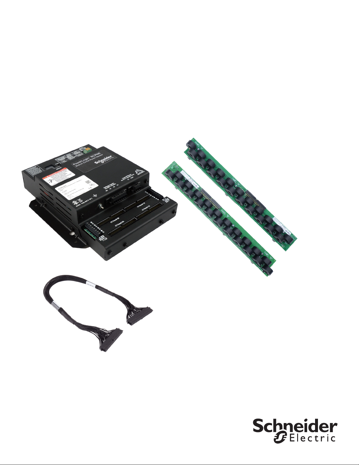
The PowerLogic™ BCPME is designed to measure the current, voltage, and
energy consumption of up to 92 circuits (84 branch circuits, two 3-phase mains,
two neutrals), enabling users to monitor two panelboards or an entire data
center PDU with a single product. It increases the board’s current monitoring
capability by combining the functions of two boards into one device. It also
includes Ethernet capability, allowing communication in multiple protocols.
The BCPME consists of a data acquisition module and up to four current sensor
strips, with eight auxiliary inputs. The strips have rows of solid-core CTs and
are mounted on each side of the panel board along the termination points of
each breaker. The conductor passes through the appropriate current sensor
before terminating at the breaker. Each strip transmits the current data to the
data acquisition board. The BCPME measures both current and power for the
mains and branch circuits. The BCPME can easily accommodate different panel
congurations, including any combination of multi-phase breaker positions,
voltage phase mapping, and breaker sizes. To congure the BCPME for
operation, use the Schneider Electric ION Setup conguration software tool.
Get the latest version at https://schneider-electric.box.com/ionsetuplatest.
Data is transmitted via Ethernet with Modbus TCP, BACnet IP, or SNMP
protocol, or via RS-485 with Modbus RTU or BACnet MS/TP protocols. Some
protocols can be used simultaneously, and the Ethernet protocols all support
access by multiple masters. Each data acquisition board requires two Modbus
addresses, one for each set of two current sensor strips and four auxiliary
inputs (two-strip models only require one Modbus address. As a circuit exceeds
the user-dened thresholds, the BCPME activates the event indicators. The
communication interfaces and protocols require some conguration at the time
of installation.
2
© 2020 Schneider Electric All Rights Reserved.
Z206856-0D
04/2020
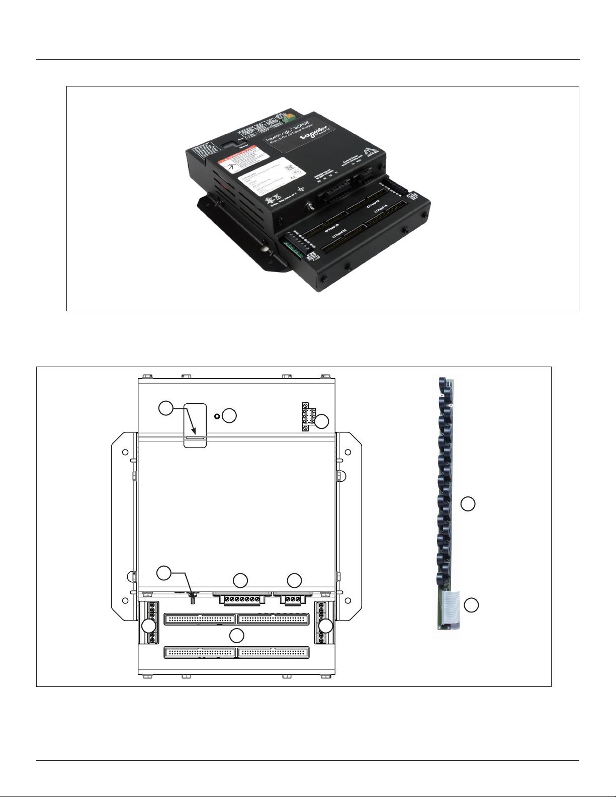
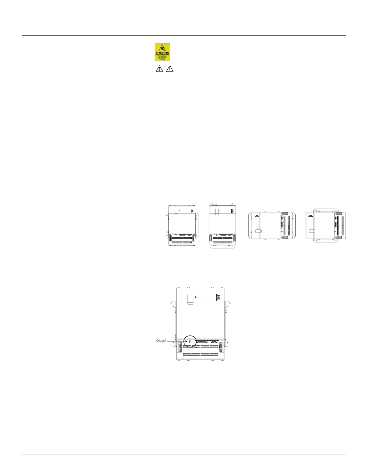
Figure 1 Branch Circuit Power Meter with Ethernet Communication
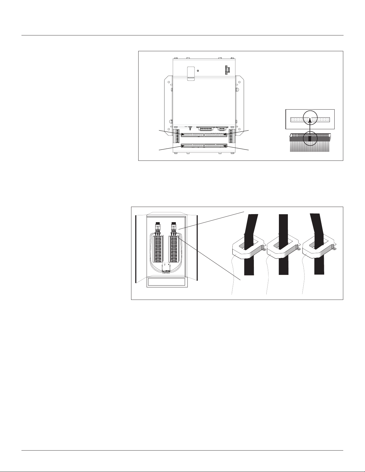
Parts of the BCPME
Figure 2 shows the parts of the BCPME, while Table 2 describes these parts.
Branch Circuit Power Meter with Ethernet Communication
Introduction
Figure 2 BCPME Panel Board Monitoring System
1
4
7 7
2
8
3
9
65
10
© 2020 Schneider Electric All Rights Reserved.
3
Branch Circuit Power Meter with Ethernet Communication
Introduction
Z206856-0D
Table 2: Parts Description of the BCPME
Part Description
1 Ethernet port Provides Ethernet connection for the gateway component.
2 Power LED Indicates power is applied to the meter.
3 2x3 RS-485 serial connection Used for Modbus, BACnet, and SNMP serial communications.
4 Protective ground connection Provides a grounding point for the device.
5 Voltage taps 1, 2, or 3 phase plus neutral connections. For voltage sensing and power calculations.
6 Control power connection Provides power to operate the meter.
7 Auxiliary CT inputs These 0.333 Vac inputs are used for monitoring the main breaker or other high amperage source.
8 50-pin ribbon cable connectors 48-inch (1220 mm) ribbon cables are provided for easy connection of the current sensor strips to this
9 Branch current sensors Each current sensor is capable of monitoring conductors rated up to a maximum of 100 amps.
10 50-pin ribbon cable connectors (branch current sensor
strips)
Dimensions
Inputs on the left are for panelboard 2; inputs on the right are for panelboard 1.
point of the data acquisition board. Other ribbon cable lengths are available (sold separately) The two
connectors on the left are for panelboard 2; the two on the right are for panelboard 1. Connect current
sensor strips to the correct ribbon cable connectors for each panel. The top connectors are for the strip
labeled Panel B, and the bottom connectors are for the strip labeled Panel A.
Connects current signal from the current sensor strip to the main board via the ribbon connectors.
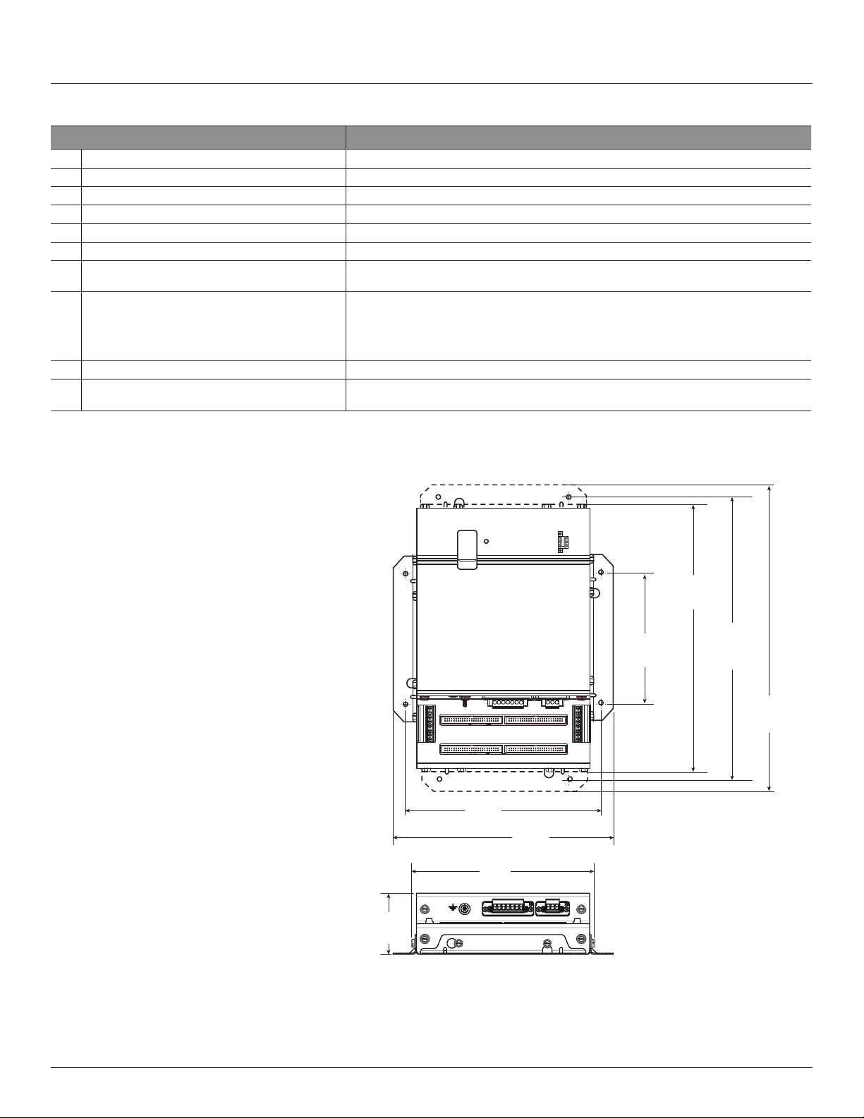
Figure 3 Data Acquisition Board and Mounting Bracket
04/2020
2.8”
(71 mm)
8.9”
(225 mm)
8.2”
(210 mm)
10.0”
(253 mm)
12.1”
(307 mm)
2x: 5.9”
(150 mm)
Note: The dotted lines
indicate dimensions if the
two brackets are placed in
the alternate orientation. At
the factory, the brackets are
placed as shown with solid
lines. See the Installation
section for more information.
12.8”
(325 mm)
13.9”
(353 mm)
4
© 2020 Schneider Electric All Rights Reserved.
Z206856-0D
04/2020
Branch Circuit Power Meter with Ethernet Communication
Introduction
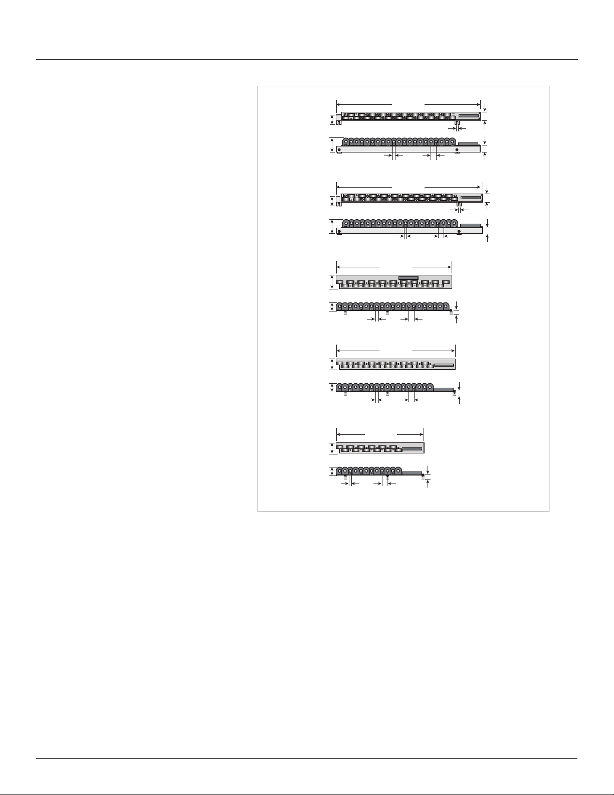
Figure 4 Current Sensor Strips
3/4"
option,
21 CTs
1”
option,
21 CTs
18 mm
option,
21 CTs
18 mm
option,
18 CTs
1.3”
(33 mm)
2.0”
(50 mm)
1.2”
(30 mm)
2.0”
(50 mm)
2.0”
(50 mm)
1.3”
(32 mm)
1.7”
(43 mm)
1.3”
(32 mm)
15.7” (399 mm)
0.4” (10 mm)
opening
16.4” (417 mm)
0.4” (10 mm)
opening
20.3” (516 mm)
0.4” (10 mm)
opening
25.0” (635 mm)
0.4” (10 mm)
opening
0.7” (18 mm)
on center
0.7” (18 mm)
on center
slot: 0.25” x 0.5”
(7 x 13mm)
0.75” (19 mm)
on center
slot: 0.25” x 0.5”
(7 x 13mm)
1.0” (26 mm)
on center
21.2”
(0.9 mm)
21.2”
(0.9 mm)
1.1”
(28 mm)
0.8”
(20 mm)
1.2”
(31 mm)
0.8”
(20 mm)
Data Output
0.4” (10 mm)
opening
12.3” (312 mm)
0.7” (18 mm)
on center
21.2”
(0.9 mm)
18 mm
option,
12 CTs
1.7”
(43 mm)
1.3”
(32 mm)
The BCPME provides several types of measurements that give a
comprehensive view of power consumption for every load on the panel:
• Real-time measurements: A live and up-to-date view of present power
levels and the factors that affect them.
• Demand measurements: Averages of values measured over a
specied time interval. The time interval (typically 15 minutes) can
be set from 10 seconds to more than a day. The demand calculation
can be congured to use single intervals or the sliding average of
up to 6 sub-intervals. Demand measurements are useful for tracking
or graphing load levels over time to correlate with total energy
consumption.
• Historic maximum measurements: These measurements store the
largest value recorded for a specic measurement since the last time
they were cleared. They are useful for identifying peak levels critical to
equipment sizing or demand limits in utility agreements.
• Accumulated energy measurements: Ongoing totals of cumulative
energy used since the last time the value was cleared. Energy values
provide the informational basis for billing, cost allocation, carbon
offset, BTU equivalent calculations, and other applications of overall
energy use.
© 2020 Schneider Electric All Rights Reserved.
5

Branch Circuit Power Meter with Ethernet Communication
Introduction
Z206856-0D
04/2020
• Energy snapshots: Energy totals that only change when the demand
intervals are updated. They are samples of the free-running energy
accumulators at the end of each demand interval, as congured by the
user. These provide energy readings that are easily correlated to the
demand values to simplify the tasks of sub-billing and cost allocation.
• Over-threshold Events (previously referred to as Alarms): Provide a
warning of excessively high or low current on each branch and aux
channel. The user can set two high-level and two low-level thresholds,
and a delay time for latching events. Events are reported as both
non-latched events and latched events. Non-latching events are active
while the current exceeds the threshold, but go inactive if the current
returns to a level within the specic thresholds. Latching events
become active when the current exceeds the threshold for a time
period greater than the specied delay and remain active until they
are cleared remotely. Event status can be polled via any protocol. Via
BACnet, Subscribe_COV can be used to generate event notications.
Via SNMP, they drive SNMP event notications.
Advanced Features - The BCPME supports a number of advanced features.
Some are always active, and others are congured manually via Modbus
register 62017, BACnet object AV164, or SNMP MIB variable “spanels/
panel1/p1Conguration/p1Setup/p1UserDenedSettings” (OID .1.3.6.1
.4.1.3833.1.30.1.1.6.3.4.0). For models with 42 channels or more, these
features are congured independently for each panel.
• Logical meter support: The BCPME can be congured to map any set
of 1, 2 or 3 channels that are adjacent in the panel to a logical meter,
referred to in the point map as a logical circuit, that provides accurate
multi-phase measurement totals. Map these logical circuits by writing
the desired logical circuit number into a set of registers/data objects
provided for each branch and aux channel (per panel).
• The channels assigned to each logical circuit must be adjacent in
the panel (usually used for multi-phase breakers), but there are no
limitations on where those adjacent channels are aligned in the panel
(any position where a multi-phase breaker can be installed). This
functionality is always active, but a user selection affects the how the
data can be accessed via Modbus. Measurement data via Modbus
for logical circuits is presented in two ways, arranged either by logical
circuit number (looks more like a collection of individual meters) or by
measurement type (arranged similar to the single-phase data section
of the point map).
• Legacy point map or alternate logical circuit point map: The BCPME
can be congured to select a preferred version of the Modbus
registers in the address range 4000 to 9999. If enabled (default), the
logical circuits by measurement type is active. Otherwise, the legacy
point maps for 2-phase and 3-phase breakers used in BCPM models
with a rmware version earlier than 1.023 is active. The logical circuits
functionality can also be accessed via the “Logical Circuits by Circuit”
section of the point map (address range 10000 to 45000), regardless
of the state of this selection.
• Phase angle measurements: The BCPME measures the phase angle
of every voltage and current input and presents these measurements
(in degrees) in additional data registers/objects. These values are
used to verify that current inputs are assigned to the proper voltage
phases and to help determine how power factor variations are
inuenced by current phase changes vs. harmonic distortion. Phase
angle measurements are instantaneous and always active.
• User CT phase assignment: In the default mode, the BCPME assigns
each channel to the corresponding phase that most 3-phase panels
implement, so that the user does not have worry about it. The user
can opt to replace this self-assignment paradigm with a mode that
6
© 2020 Schneider Electric All Rights Reserved.

Z206856-0D
04/2020
Branch Circuit Power Meter with Ethernet Communication
Introduction
allows explicit specication of the phase assignment for each channel.
The explicit assignments set by the user are stored by the BCPME in
non-volatile memory.
• Phase angle reference: The BCPME measures the phase angle of
every current and voltage input. The user can select whether the
phase angles are stated relative to an absolute reference (the phase
angle of voltage input V1) or relative to the voltage phase assigned to
that specic current input channel.
• Demand/snapshot time interval source: The BCPME offers two
mechanisms for driving the demand/snapshot time interval, an interval
timer or an RTC (real-time clock). The legacy mode (default) uses an
interval timer that does not need to be set to an absolute time. When
using the interval timer the demand/snapshot interval can be set from
10 to 32767 seconds (over 9 hours). An alternate mode utilizes an
RTC set to a specic date and time to synchronize the results with a
larger system. The RTC must rst be set in order to run and capture
demand values and energy snapshots. When power is interrupted, the
RTC resets to a default date and time and must be set again in order
to run. When using the RTC, the demand/snapshot interval can be set
from 10 to 3600 seconds (1 hour).
Table 3: Data Outputs Table
Monitoring of Mains
Current: multi-phase average and per phase
Current phase angle
Real power (kW): multi-phase total and per phase
Real Time
Measurements
Demand Measurements
Historic Maximums
Accumulated Energy Energy (kWh): multi-phase total and per phase
Energy Snapshots Energy (kWh): multi-phase total and per phase
Apparent power (kVA): multi-phase total and per phase
Power factor: multi-phase average and per phase
Voltage - L-L: multi-phase average and per phase
Voltage - L-N: multi-phase average and per phase
Frequency (phase A)
Current present demand: multi-phase average and per phase
Real Power (kW) present demand: multi-phase average and per phase
Maximum instantaneous current: multi-phase average and per phase
Maximum current demand: multi-phase average and per phase
Maximum real power demand: multi-phase total and per phase
Monitoring of Branch Circuits
Current: multi-phase average and per phase
Real Time
Measurements
Demand Measurements
Historic Maximums
Accumulated Energy Energy (kWh): multi-phase total and per phase
Energy Snapshots Energy (kWh): multi-phase total and per phase
Current phase angle per branch
Real power (kW): multi-phase total and per phase
Apparent power (kVA): multi-phase total and per phase
Power factor: multi-phase average and per phase
Current present demand: multi-phase average and per phase
Real power (kW) present demand: multi-phase average and per phase
Maximum instantaneous current: multi-phase average and per phase
Maximum current demand: multi-phase average and per phase
Maximum real power demand: multi-phase total and per phase
© 2020 Schneider Electric All Rights Reserved.
7
Branch Circuit Power Meter with Ethernet Communication
A qualified person is one who has skills and knowledge related to
the construction and operation of this electrical equipment and
installations, and has received safety training to recognize and
avoid the hazards involved.
If this product is used in a manner not specified by the
manufacturer, the protection provided by the product may be
impaired. No responsibility is assumed by Schneider Electric for
any consequences arising out of the use of this material.
DANGER
Installation
Solid Core Branch Current Sensors
Installation
Modbus Events
Voltage over/under
Events
Branch current over/under
Mains current over/under
Table 4: Branch Current Sensor Specs
100 A Solid-Core Branch Current Sensors
Voltage Rating 300 Vac
Measurement Range 120 A*
Temperature 0 to 60 °C (32 to 122 °F)
Agency EN61010-1
*Momentary.
Z206856-0D
04/2020
HAZARD OF ELECTRIC SHOCK, EXPLOSION, OR ARC
FLASH
• Follow safe electrical work practices. See NFPA 70E in the
USA, CSA Z462 in Canada, or applicable local codes.
• Read and understand the instructions before installing the
product. Follow the instructions during installation.
• Installation, wiring, testing or service must be performed
only by qualified persons in accordance with all applicable
codes and regulations.
• Install the product in an appropriate electrical and fire
enclosure per local regulations.
• Do not use the product for life or safety applications.
• Do not install the product in hazardous or classified locations.
• Do not exceed the product’s ratings or maximum limits.
• The product may use multiple voltage/power sources.
• Turn off ALL power supplying equipment before working on
or inside the equipment.
• Use a properly rated voltage sensing device to confirm that
all power is off.
• Do NOT depend on the product for voltage indication.
• Products rated only for basic insulation must be installed on
insulated conductors.
• Current transformer secondaries (current mode) must be
shorted or connected to a burden at all times.
• Remove all wire scraps and tools, replace all doors, covers
and protective devices before powering the equipment.
Failure to follow these instructions will result in death or
serious injury.
8
NEC Article 100
© 2020 Schneider Electric All Rights Reserved.
Z206856-0D
04/2020
Branch Circuit Power Meter with Ethernet Communication
Observe precautions for handling static sensitive
devices to avoid damage to the circuitry that
is not covered under the factory warranty.
Installation
The protective ground connection on the housing should be used
if the device will not be mounted to a suitably grounded surface. Assure
conductivity to the protective ground.
1. Always use a properly rated voltage sensing device to conrm power is off.
2. Determine where you will mount the BCMPE measurement unit. The
preferred location is inside the enclosure of the panelboard being
monitored. If sufcient space is not available there, then mount the unit in
an appropriate enclosure nearby. Decide whether to mount it vertically or
horizontally. The meter is shipped with the brackets placed on the two sides
for vertical mounting. If desired, you can move the brackets from the sides
to the ends of the housing. Loosen the screws on the sides of the BCPME
that hold the brackets in place (do not fully remove the screws from the
housing). Loosen the screws on the two ends of the housing (do not fully
remove the screws from the housing), and set the brackets into their new
positions. Tighten all screws to 25 in-lb (2.8 N-m).
Figure 5 Brackets positioned for vertical and horizontal mounting
Vertical Mounting Horizontal Mounting
Install the BCPME in the panel. A grounding connection is located on the
housing (see below).
Figure 6 BCPME Ground stud
Ground
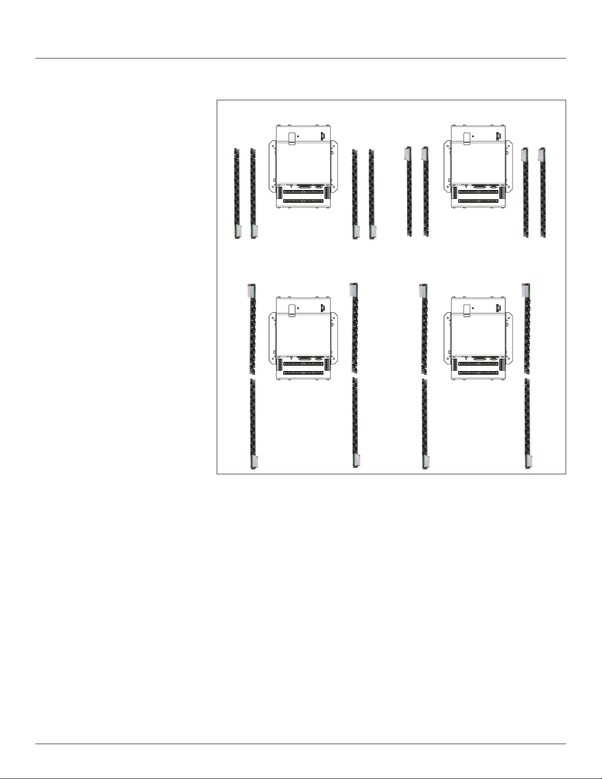
3. Install the branch current sensor strips into the panel. Select one of the four
circuit congurations shown below and arrange the CTs strips accordingly.
For more detailed installation diagrams and help identifying what circuit
conguration setting to use, refer to the appendix titled: Panel Conguration
Diagrams and Selection Matrix. Adjust conguration of the circuit numbers
in the eld during commissioning by writing to Modbus Register 6 (or
the corresponding BACnet object or SNMP variable) or use ION Setup
conguration software. Most of the examples in this graphic show the 21
current sensor strips. The same conguration options are available for the
18 and 12 current sensor strips.
© 2020 Schneider Electric All Rights Reserved.
9
Branch Circuit Power Meter with Ethernet Communication
Installation
Top Feed Bottom Feed
Z206856-0D
04/2020
Figure 7 Current sensor strip configuration selections (must be
set during commissioning - default is "Top Feed")
B
A
2
1
4
3
6
5
8
7
10
9
12
11
14
13
16
15
18
17
20
19
22
21
24
23
26
25
28
27
30
29
32
31
34
33
36
35
38
37
40
39
42
41
Panel 1Panel 2 Panel 1Panel 2
Register 6
B
A
2
1
4
3
6
5
8
7
10
9
12
11
14
13
16
15
18
17
20
19
22
21
24
23
26
25
28
27
30
29
32
31
34
33
36
35
38
37
40
39
42
41
Value = 0
B
A
2
1
4
3
6
5
8
7
10
9
12
11
14
13
16
15
18
17
20
19
22
21
24
23
26
25
28
27
30
29
32
31
34
33
36
35
38
37
40
39
41
42
Register 6
Value = 1
(Default)
Single Row: Sequential Single Row: Odd/Even
A
1
2
3
4
5
6
7
8
9
10
11
12
13
14
15
16
17
18
19
20
21
22
B
23
24
25
26
27
28
29
30
31
32
33
34
35
36
37
38
39
40
41
42
Panel 1Panel 2 Panel 1Panel 2
Register 6
Value = 2
A
1
2
3
4
5
6
7
8
9
10
11
12
13
14
15
16
17
18
19
20
21
22
B
23
24
25
26
27
28
29
30
31
32
33
34
35
36
37
38
39
40
41
42
A
1
3
5
7
9
11
13
15
17
19
21
23
25
27
29
31
33
35
37
39
41
2
B
4
6
8
10
12
14
16
18
20
22
24
26
28
30
32
34
36
38
40
42
Register 6
Value = 3
B
A
2
1
4
3
6
5
8
7
10
9
12
11
14
13
16
15
18
17
20
19
22
21
24
23
26
25
28
27
30
29
32
31
34
33
36
35
38
37
40
39
42
41
A
1
3
5
7
9
11
13
15
17
19
21
23
25
27
29
31
33
35
37
39
41
2
B
4
6
8
10
12
14
16
18
20
22
24
26
28
30
32
34
36
38
40
42
10
4. Verify that the serial numbers printed on the branch current sensor strips
and on the BCPME match. The board and the strips are sold as a calibrated
set.
5. Connect the current sensor ribbon cables to the 50-pin connectors on
the BCPME. The label on the strip indicates which connector to use (e.g.
connect the strip labeled “Panel 1A” to the bottom right connector on the
board). Orient the cables so that the plastic key on the BCPME connector
aligns with the keyhole cutout on the ribbon cable connector, as shown
below.
© 2020 Schneider Electric All Rights Reserved.
Z206856-0D
04/2020
Branch Circuit Power Meter with Ethernet Communication
Installation
Figure 8 Connector orientation
Align ribbon
cable key with
connector
keyhole.
Aux CT Installation
Panel 2,
Strip B
Panel 2,
Strip A
Panel 1,
Strip B
Panel 1,
Strip A
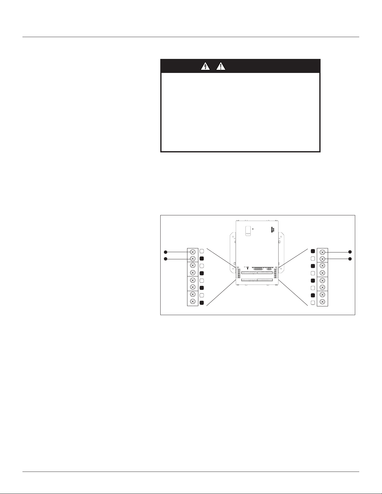
1. Connect 0.333 Vac current transformers (CTs) to the mains or other
conductors, observing local codes regarding bending radius. Refer to the
appropriate CT installation instructions for further information.
Figure 9 CT connection
Panel 2 Panel 1
E30 CURRENT SENSOR STRIP
E30 CURRENT SENSOR STRIP
E30 CURRENT SENSOR STRIP
E30 CURRENT SENSOR STRIP
© 2020 Schneider Electric All Rights Reserved.
NOTE: The BCPME measures and reports the phase angle of each
voltage input and each CT (when there is active current through the
primary of that CT).
11
Branch Circuit Power Meter with Ethernet Communication
DANGER
Installation
Wiring
Z206856-0D
04/2020
HAZARD OF ELECTRIC SHOCK, EXPLOSION, OR
ARC FLASH
• While removing or installing panels and covers, assure that
they do not contact an energized bus.
• NEVER bypass external fusing.
• NEVER short the secondary of a potential transformer.
• Before closing covers and doors, carefully inspect the work
area and remove any tools, wire scraps or other objects that
may have been left inside the equipment.
Failure to follow these instructions will result in death or
serious injury.
NOTE: For all steps in this section, when tightening terminals, apply
the correct torque: Aux Inputs: 3.5 to 4.4 in-lb (0.4 to 0.5 N-m); all
other terminals: 4.4 to 5.3 in-lb (0.5 to 0.6 N-m).
1. Wire the (optional) 0.333 V Aux CTs to the BCPME (see Figure 10),
observing local codes regarding bending radius. Refer to the appropriate
CT installation instructions for further information.
Figure 10 Aux CT wiring
CT Input
(0 to 0.333 Vac)
X1 X1 X1 X1
N 3 2 1
X2 X2 X2 X2
CT Input
(0 to 0.333 Vac)
X2 X2 X2 X2
1 2 3 N
X1 X1 X1 X1
2. Connect 2-wire 100 to 277 Vac power to the control power terminals.
Observe polarity. Connect voltage lines to the voltage inputs. Provide
overcurrent protection and disconnecting means to protect the wiring. Use
EMFP1, EMFP2, EMFP3 fuse packs, or equivalent. Suggested: 0.5 A, time
delay fuses.
12
© 2020 Schneider Electric All Rights Reserved.
Z206856-0D
3-wire (ungrounded)
Corner-grounded
4-wire
3-wire
2-wire
Single-phase
120/240V High-Leg
L2
04/2020
Branch Circuit Power Meter with Ethernet Communication
Installation
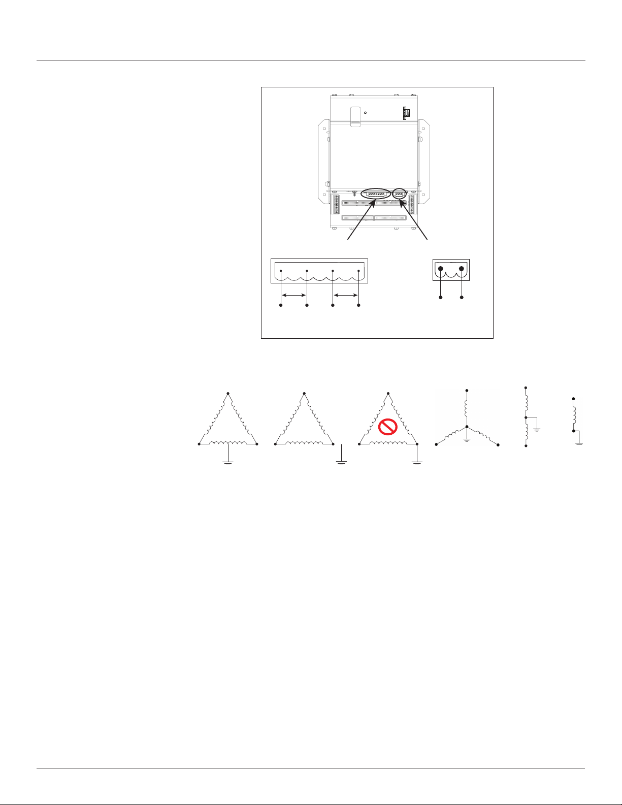
Figure 11 Connect to voltage inputs
Voltage taps are shared by both panels.
Delta
L3
N
N
L1 L2 L1
120 V/240 V Delta High Leg (where the center tap of one of the three
phase-to-phase transformers is grounded): the BCPME supports these
applications, as long as the line-to neutral voltage [especially of the High Leg]
does not exceed 300 Vac (as in North American 120/240 V High Leg Delta
congurations).
Voltage Inputs
90 to 300 V 50/60 Hz
N V3 V2 V1
L-N V1 V2/NL-L
Figure 12 Wiring configurations
Delta
L3 L3
X
Delta
L2 L1
Control Power
100 to 277 V 50/60 Hz 15 VA
V1 V2/N
Wye
L3
N
L2 L1
Split-phase
L2
L1
N
N
L1
© 2020 Schneider Electric All Rights Reserved.
In 3-wire (ungrounded) Delta applications, the BCPME supports these
applications with the following caveats:
Control Power for the meter cannot exceed 277 Vac. In applications
where the L-L voltage is 277 Vac or less (e.g. 208 V line-to-line) it can be
connected to two of the phases being monitored without exceeding the
limit. For higher voltages (e.g. 480 V line-to-line), this must be supplied
from a source that is 277 Vac or less. It could be a separate source or
a transformer can be used to step it down from two of the phases being
measured.
All of the CT inputs (both branches and Aux inputs) are neutral-referenced.
One side of each CT is essentially connected directly to the neutral voltage
input. If this is left oating, the solid-core CT strips, split-core CT adapter
boards and all CTs will oat at the same potential (while the panel is
energized). This does not present a risk to the equipment as long as it is
within 300 V of ground, but should be considered from a safety perspective
in the overall application. The BCPME will provide measurements in this
application with the accuracy specied, with the exception of line-to-neutral
13
Branch Circuit Power Meter with Ethernet Communication
Installation
Z206856-0D
04/2020
voltages, which will be calculated and reported, based on a derived virtual
neutral voltage, even though they are not relevant.
Corner-grounded delta: the BCPME does not support these applications at any
voltage level.
The BCPME supports measurement of all 4-wire Wye, 3-wire split-phase and
2-wire single phase and congurations that operate between 90 and 300 Vac
line-to neutral.
3. Connect the 2-wire Modbus RS-485 network.
Figure 13 RS-485 connection
RS-485
S
–
+
S
–
+
4. Mechanically secure the RS-485 cable(s) where they enter the electrical
panel.
5. If using Modbus RTU or BACnet MS/TP protocol, connect a serial cable(s)
from the RS-485 loop to the serial connector on the BCPME. Connect all
RS-485 devices in a daisy-chain, and properly terminate the chain.
Figure 14 Daisy chain connection
120 Ω terminator
where specied
RS-485
S
–
+
S
–
+
RS-485 cable
by the applicable
standard
Two sets of connections are provided to simplify daisy-chain connections
and enable retention of each wire.
14
© 2020 Schneider Electric All Rights Reserved.
Z206856-0D
04/2020
Branch Circuit Power Meter with Ethernet Communication
Installation
Follow all applicable wiring and termination connection guidelines for the
standard in use. Note that while both the Modbus RTU and BACnet MS/
TP standards identify requirements for RS-485 line polarization/bias and
termination, the value and placement of these resistors varies for each
standard. The BCPME does not implement any RS-485 line polarization/
bias or termination internally. Shield the RS-485 cable using twisted-pair
wire. Use cable that is voltage-rated for the installation. The shield is not
internally connected to Earth Ground. Connect the shield to Earth Ground
somewhere on the RS-485 bus (single point connection only).
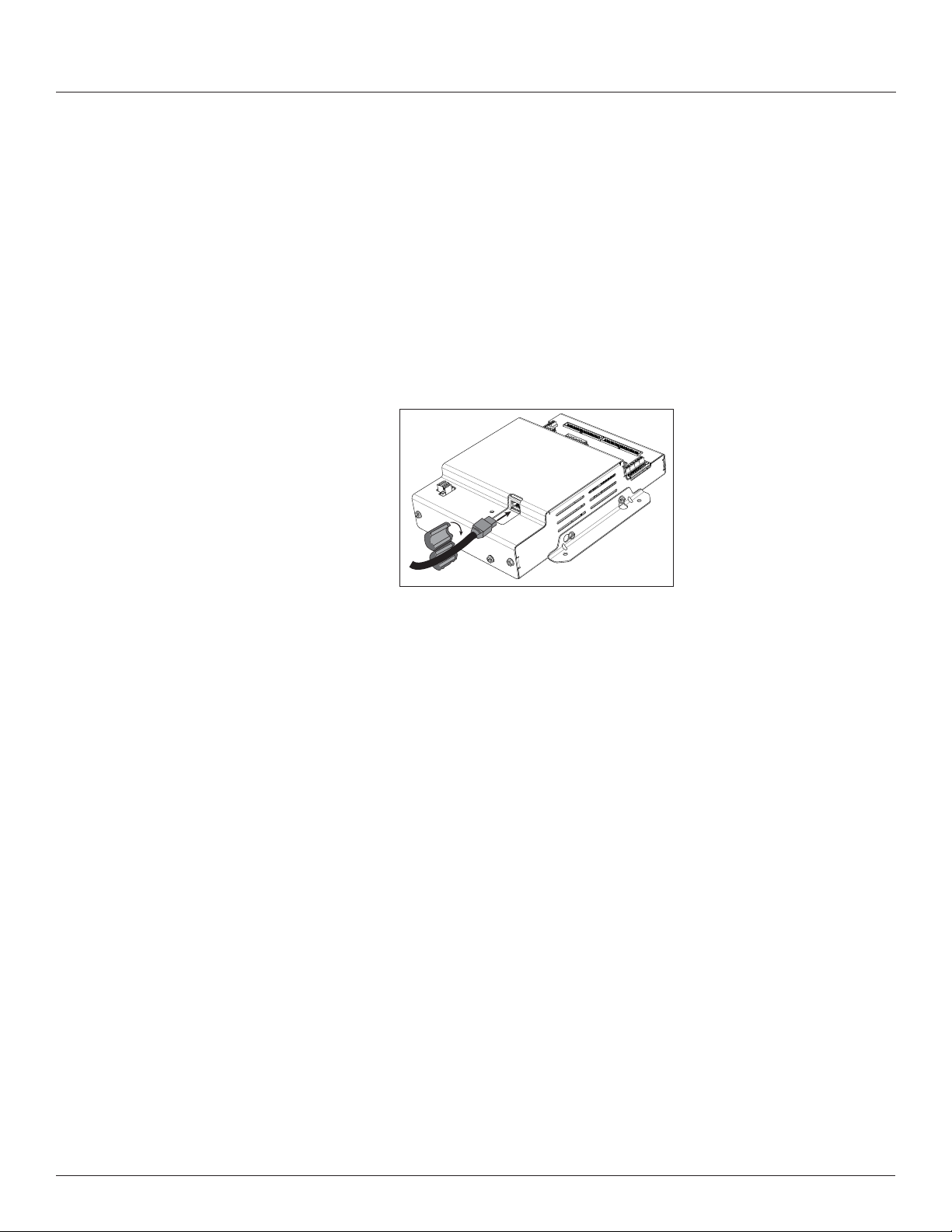
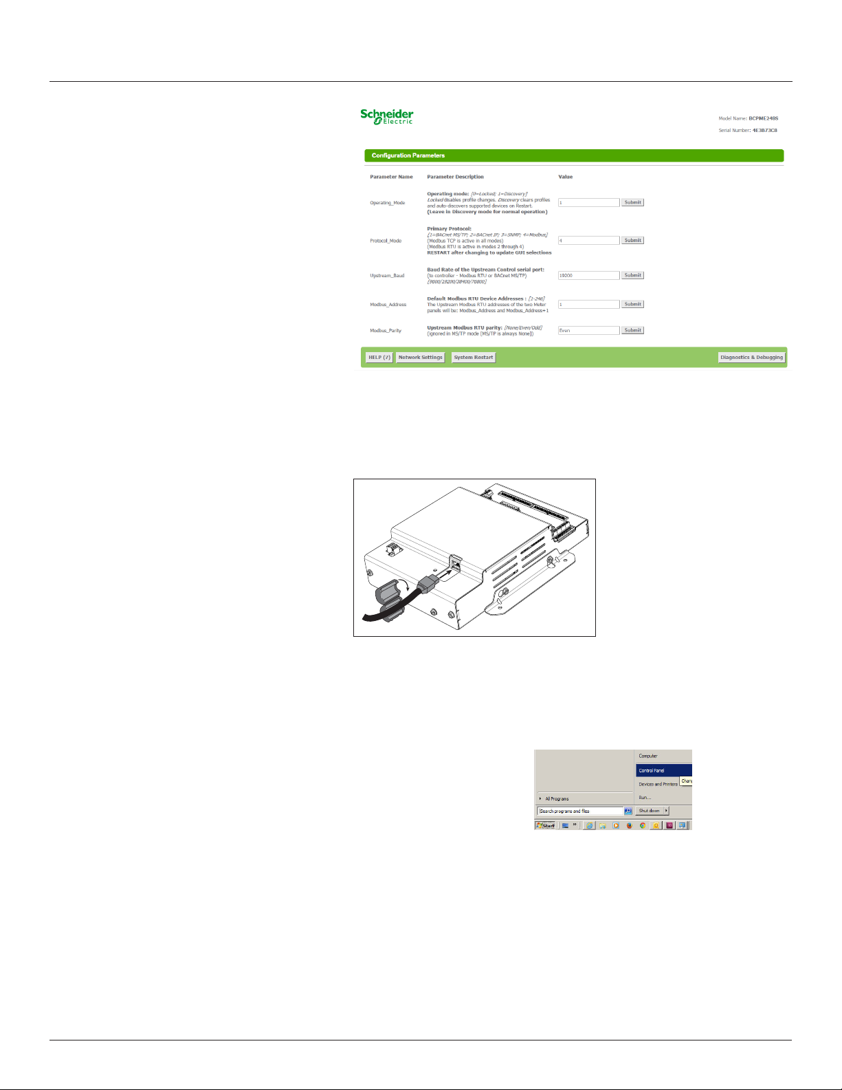
6. Connect an Ethernet cable to a local PC. Secure a ferrite lter (included)
around the Ethernet cable to ensure the device meets emission
requirements. Use the PC to congure the gateway (next section of this
document). Note: 100 to 277 Vac must be added to control power inputs to
supply power to the gateway during conguration.
Figure 15 Ethernet port location
7. Once congured, disconnect the local PC. If desired (and the device is
congured for operation on the network), connect the BCPME directly to
the network for ongoing access to the GUI even if primarily using a serial
protocol to access and control the BCPME.
© 2020 Schneider Electric All Rights Reserved.
15

Branch Circuit Power Meter with Ethernet Communication
A qualified person is one who has skills and knowledge related to
the construction and operation of this electrical equipment and
installations, and has received safety training to recognize and
avoid the hazards involved.
If this product is used in a manner not specified by the
manufacturer, the protection provided by the product may be
impaired. No responsibility is assumed by Schneider Electric for
any consequences arising out of the use of this material.
DANGER
Installation
Gateway Configuration
Z206856-0D
04/2020
HAZARD OF ELECTRIC SHOCK, EXPLOSION, OR ARC
FLASH
• Follow safe electrical work practices. See NFPA 70E in the
USA, CSA Z462 in Canada, or applicable local codes.
• Read and understand the instructions before installing the
product. Follow the instructions during installation.
• Installation, wiring, testing or service must be performed
only by qualified persons in accordance with all applicable
codes and regulations.
• Install the product in an appropriate electrical and fire
enclosure per local regulations.
• Do not use the product for life or safety applications.
• Do not install the product in hazardous or classified locations.
• Do not exceed the product’s ratings or maximum limits.
• The product may use multiple voltage/power sources.
• Turn off ALL power supplying equipment before working on
or inside the equipment.
• Use a properly rated voltage sensing device to confirm that
all power is off.
• Do NOT depend on the product for voltage indication.
• Products rated only for basic insulation must be installed on
insulated conductors.
• Current transformer secondaries (current mode) must be
shorted or connected to a burden at all times.
• Remove all wire scraps and tools, replace all doors, covers
and protective devices before powering the equipment.
Failure to follow these instructions will result in death or
serious injury.
Accessing the Graphical User Interface (GUI)
16
NEC Article 100
Note: The screen captures in this section were taken using Windows 7; other
operating systems will look different.
If the BCPME IP address parameters are already congured to work on the
network and is being accessed from a PC on that same network, then open a
web browser and enter the IP address of the BCPME into the address/URL eld
on the browser. Press enter. On the rst time login to the device GUI, follow the
instructions in the section "Accessing the GUI for the rst time with rmware
version 1.027 or higher" to congure the web server's security settings and
log in. If already congured, the GUI login page appears. Enter the username
and password and click Login. The GUI launches and appears, as shown, in the
browser window below.
Note: Devices with rmware version 1.026 and earlier will not have a login page
and will not require a password.
© 2020 Schneider Electric All Rights Reserved.
Z206856-0D
04/2020
Branch Circuit Power Meter with Ethernet Communication
Installation
If the IP address parameters are not congured for the network, connect a PC
directly and access the GUI from it as follows:
1. Connect a standard Ethernet cable between a PC and BCPME if not
already connected. Secure a ferrite lter (included) around the Ethernet
cable to ensure the device meets emission requirements.
2. Temporarily change the IP address of the PC to a static value on the same
subnet as the BCPME. For example: If the BCPME is set to its factory
default IP address of 192.168.1.24, set the PC to an unused static IP
address on the 192.168.1.xxx subnet (where xxx is any value between 1
and 255, except 24). Set the subnet mask to 255.255.255.0.
a. Open the Control Panel:
b. In the Control Panel, select Network and Sharing Center. In the Sharing
Center, select Change Adapter Settings in the list at the upper left corner.
c. Select the connection for the network that the BCPME is connected to.
© 2020 Schneider Electric All Rights Reserved.
17

Branch Circuit Power Meter with Ethernet Communication
Installation
Z206856-0D
04/2020
When the Local Area Connection Status dialog box appears, click on
Properties.
d. Highlight Internet Protocol Version 4 (TCP/IPv4), and click OK.
e. Select <Use the following IP Address>. Make note of the IP address that
appears, then enter the static IP address (e.g. if the BCPME is still set to
its default address of 192.168.1.24, then change it to 192.168.1.100). Enter
255.255.255.0 for the subnet mask. Click OK.
18
© 2020 Schneider Electric All Rights Reserved.

Z206856-0D
04/2020
Branch Circuit Power Meter with Ethernet Communication
Installation
Enter static
IP address
Enter subnet
mask
e. Click OK.
3. Open a PC web browser and enter the IP address of the BCPME (default
address is 192.168.1.24) to access the GUI. On the rst time login to the
device GUI, follow the instructions in the section "Accessing the GUI for
the rst time with rmware version 1.027 or higher" to congure the
web server's security settings and log in. The GUI launches and appears in
the browser window.
Using the GUI to set up the IP address
4. When nished using the GUI, unplug the Ethernet cable from the PC and
restore the IP settings as needed.
1. Access the GUI according the instructions in the “Accessing the Graphical
User Interface (GUI)” section. To set IP address parameters, click the
button labeled “Network Settings.”
© 2020 Schneider Electric All Rights Reserved.
The Network Settings screen appears.
19

Branch Circuit Power Meter with Ethernet Communication
Installation
Z206856-0D
04/2020
Have the desired IP settings ready in advance (contact the system
administrator). IP parameters for use with BACnet IP are static, not
dynamic.
2. Set the IP address for use on the BACnet/IP network:
a. Enter the desired IP address in the N1_IP_Address eld (in the format
xxx.xxx.xxx.xxx)
b. If necessary, change the Subnet Mask by entering the appropriate new
value in the N1_Netmask eld
c. If the BCPME is connected to an Ethernet gateway, enter its IP address
in the Default Gateway eld. This is especially critical if the BCPME will be
used as a BACnet BBMD device.
d. Click the Update IP settings button. The BCPME changes its settings.
e. Click the System Restart button and wait for the BCPME to fully
initialize. The GUI will connect when the BCPME is installed on a network
that matches the settings and the new IP address is entered into a web
browser on a PC properly congured for the network.
Using the GUI to Configure the Communication Protocols
Access the GUI according the instructions in the “Accessing the Graphical User
Interface (GUI)” section.
20
© 2020 Schneider Electric All Rights Reserved.

Z206856-0D
04/2020
Branch Circuit Power Meter with Ethernet Communication
Installation
The home screen on the GUI provides elds for conguration of the BCPME.
The BCPME has four primary modes of operation, each of which support a
different combination of protocols. Each option eld has a Submit button to
the right. When changing the value in any eld, click Submit to store the new
value. The GUI prompts the user to restart the system. If multiple values are
changed, it is easiest to submit all changes and restart only once when nished
with the whole screen. To restart, click the System Restart button in the row
at the bottom of the screen. The restart takes several seconds, during which
the server may lose its connection. Messages appear at the top of the screen
indicating current status, but do not perform any actions. Simply allow the tool
to complete the restart cycle.
The rst selection in the GUI is Operating_Mode, which has two choices:
a. Locked: used for all normal product operation. It is provided as a tool
for high-level technical support. The gateway retains its current prole
conguration when powered.
b. Discovery mode (default): deletes proles and rediscovers them when
the device is powered again. The results are the same, unless the prole
conguration is intentionally altered. Prole selection and discovery are
especially important when using BACnet or SNMP protocols. For normal
operation, always use discovery mode.
The second selection in the GUI is Protocol_Mode, used to select the
combination of protocols the product communicates with. The BCPME supports
ve protocols, some of which can operate simultaneously. The table below
shows what protocols are supported in each mode.
Protocol
Mode
1 BACnet MS/TP Modbus TCP BACnet MS/TP
2 BACnet IP BACnet IP/Modbus TCP Modbus RTU
3 SNMP SNMP/Modbus TCP Modbus RTU
4 Modbus Modbus TCP Modbus RTU
Primary
Protocol
Ethernet
Protocol
RS-485
Protocol
To select a primary protocol mode, enter the corresponding number into
the text eld adjacent to the Primary Protocol option and click the Submit
button to the right of the text eld. A prompt appears at the top of the
screen instructing the user to restart the system. When nished, the screen
refreshes itself with the appropriate elds for the selected mode.
The next GUI selection, in any protocol mode, is the Upstream_Baud rate
selection. If you have selected BACnet MS/TP (mode 1) as the primary protocol
mode, this value sets the MS/TP baud rate. If you have selected modes 2 or 3
as the primary protocol mode, you may not be using the RS-485 interface at all.
If so, this setting can be ignored.
If you have selected BACnet IP, SNMP or Modbus mode, the next selection is
Modbus_Address, which sets the Modbus address(es) for the BCPME when
access with Modbus RTU with the RS-485 serial connection.
The next selection (in BACnet IP, SNMP or Modbus modes) is Modbus_Parity,
which sets the parity of the upstream serial connection. If using Modbus RTU
protocol, set this to match your Modbus master. If not, ignore this eld.
© 2020 Schneider Electric All Rights Reserved.
The following sections show the eld selections (with factory default values)
specic to each of the four Protocol_Modes.
21

Branch Circuit Power Meter with Ethernet Communication
Installation
1. BACnet MS/TP mode
Z206856-0D
04/2020
The rst three options are discussed previously.
The DeviceID_Offset parameter is used to assign Device_IDs on power-up
or on restart until they have been overwritten via BACnet. Enter your desired
value here and click submit. The new value is rst used at the next power-up or
system restart. Valid Device_ID numbers range from 1 to 4194303. Since the
numbers assigned during discovery are the sum of the Offset and the Modbus
address (which can be any value from 1 to 247), the Offset values entered in
the GUI must be no larger than 4194057.
The BCPME gateway creates a BACnet virtual router and separate BACnet
devices for each 42-channel meter panel behind this virtual router, allowing
the devices to be discoverable and independently accessed via BACnet, even
if the virtual router is connected by MS/TP, using a single MAC address. To
use this product with MS/TP, the BACnet system must support the discovery
and use of a BACnet router on the MS/TP trunk and any devices beyond it.
This virtual router creates an exclusive BACnet network on which the meter’s
BACnet devices reside. This network must have a BACnet network number
that is different from any other networks in the entire BACnet enterprise. When
multiple BCPME products are added anywhere in the enterprise, each one must
have a unique network number. Failure to set an exclusive value in this eld
causes communication conicts in the BACnet system.
Enter a non-conicting value here and click submit. Valid network numbers
range from 1 to 65534; if other values are entered, the network number defaults
to 5. The new value is rst used at the next power-up or system restart. If using
an external BACnet router to connect the BCPME as an MS/TP device, it is
recommended that the router also be restarted after the BCPME has completed
discovery, when the network number is changed.
22
© 2020 Schneider Electric All Rights Reserved.

Z206856-0D
04/2020
2. BACnet IP mode
Branch Circuit Power Meter with Ethernet Communication
Installation
The next eld for the BACnet MS/TP protocol mode is the MSTP_Max_Master,
which allows this value to be set prior to using BACnet software to access the
BCPME. The default value of 127 works regardless of the addresses the MS/TP
network uses, but selecting a lower value may optimize the network. Do not set
this value lower than the highest address on the network. To set this value via
BACnet, write to the Max_Master property of the device object for the BCPME’s
virtual router.
The next eld for the BACnet MS/TP protocol mode is the MSTP_MAC_Addr,
which sets the MAC address for the virtual router. The BCPME panel(s) are
devices on the internal BACnet network and are not directly addressable as
MAC addresses on the MS/TP network.
The nal eld for the BACnet MS/TP mode is RTC_Control, which selects which
protocol (BACnet or Modbus) has write access to the RTC. If 0 (BACnet) is
selected, the RTC is set using the BACnet Time Synchronization service. If
1 (Modbus) is selected, the RTC is set by writing to the appropriate Modbus
registers.
© 2020 Schneider Electric All Rights Reserved.
BACnet IP mode uses the same DeviceID_Offset, Virt_Router_Net and RTC_
Control parameters described above for BACnet MS/TP mode. One additional
parameter, BACnet_IP_Port, is used to set the UDP port. Most BACnet systems
use the default port (47808 decimal, 0xBAC0 hex) that is recommended in the
23

Branch Circuit Power Meter with Ethernet Communication
Commissioning
3. SNMP mode
Z206856-0D
04/2020
BACnet standard as the only UDP port. Some large systems need to segment
the enterprise and use more than port. If so, enter the number of the port you
need to use to access this device. BACnet IP mode does not use MSTP_Max_
Master or MSTP_MAC_Addr.
BACnet IP mode adds another eld called BBMD_Enable. See the section
BBMD Support for a full description of how to enable and use BBMD support.
Operating the BCPME
Commissioning
24
SNMP mode uses four unique parameters. SNMP community strings are
used to control access to the device. Whatever values are entered here must
be used in the MIB browser or SNMP access software to communicate with
this device. The Read_Community string is used to enable reading data. The
Write_Community string is used to enable writing data. The Trap_Community
string is used to enable the receipt of event notications.
The last parameter, SNMP_Notif_IP is used to set the IP address of the client
that will be used to receive SNMP event notications for over-threshold events.
Restart the BCPME by using the button at the bottom of the GUI or by cycling
the power. It takes about 30 seconds to initialize completely and be ready for
external communication.
Commission the BCPME for operation using ION Setup software. See the ION
Setup Conguration Guide for instructions.
© 2020 Schneider Electric All Rights Reserved.

Z206856-0D
04/2020
BACnet Network Management
Branch Circuit Power Meter with Ethernet Communication
Commissioning
BACnet conguration uses two default settings that might need to be changed,
depending on the application.
a. Virtual router network ID number. Every logical network segment (IP
subnet, MS/TP trunk, etc.) in an entire system must have a (16-bit) network
ID number that is unique from all other BACnet networks in the enterprise.
The BACnet network administrator assigns this network ID so that no two
ID numbers conict (whether using BACnet/IP or MS/TP). Within each
segment, every device is physically identied by the combination of its 8-bit
MAC address and the 16-bit network ID number.
To support multiple meter panels (panel 1 and panel 2 are separate) with a
single gateway, the BCPME creates a virtual BACnet router that presents
multiple BACnet devices using a single (its own) MS/TP MAC address.
Each BCPME must have its own (internal) network ID, and it creates a
device object for itself and one for each Modbus address discovered.
The factory default network address is 50 (decimal). If that number is
already in use in the system, assign a unique address using the graphical
user interface (GUI) on the built-in web server (this requires an Ethernet
connection to a web browser; see BACnet/IP Setup section for instructions
on changing conguration settings using the GUI). Valid network numbers
range from 1 to 65534; if other values are entered, the network number
defaults to 5.
b. Device_ID Offset. Every BACnet device must have a BACnet
Device_ID number that is unique throughout the entire enterprise. Since
the BCPME presents every Modbus meter as a BACnet device, each
connected meter that has a Modbus address must have a BACnet Device_
ID.
By default, each device discovered receives a Device_ID number that
is the sum of an offset value (default is 50000) and the Modbus address
of the device. If these Device_ID numbers cause a conict with existing
devices in the system, or if the system includes multiple BCPMEs, change
the Device_ID numbers before connecting the BCPME to the system. This
can be managed one of two ways:
i. Connect to the BCPME directly (ofine from the system) with the
devices (meters). After the BCPME discovers the devices and assigns
their default ID numbers, the user can choose new Device_ID values
and write these to each device using BACnet software. Subsequent
discoveries will not overwrite these values with defaults even if the
BCPME is then set to Discovery mode.
© 2020 Schneider Electric All Rights Reserved.
ii. Use the GUI on the built-in web server to modify the offset value used
to calculate default Device_IDs in the discovery process (this requires
an Ethernet connection to a web browser; see BACnet/IP Setup section
for instructions on changing conguration settings using the GUI).
The BCPME retains this offset value and uses it to assign Device_ID
numbers every time power is cycled if the BCPME is in Discovery
mode. Valid Device_ID numbers range from 1 to 4194303. Since the
numbers assigned during discovery are the sum of the Offset and
the Modbus address (which can be any value from 1-247), any Offset
values entered in the GUI must be less than 4194057.
25

Branch Circuit Power Meter with Ethernet Communication
Commissioning
BACnet PICS (Protocol Implementation Conformance Statement)
Vendor Name: Schneider Electric
BACnet Vendor ID 335
Product Name: BCPME Series Branch Circuit Monitor
Product Model Number: <Model Number>
Product Description: Branch Circuit Monitor
BACnet Protocol Version: Version 1 Revision 12
BACnet Standardized Device Prole (Annex L) – [Note: BCPME incorporates a
gateway device]
• BACnet Application Specic Controller (B-ASC)
BACnet Interoperability Building Blocks Supported (Annex K):
• K.1.2 BIBB - Data Sharing - ReadProperty-B (DS-RP-B)
• K.1.4 BIBB - Data Sharing - ReadPropertyMultiple-B (DS-RPM-B)
• K.1.8 BIBB - Data Sharing - WriteProperty-B (DS-WP-B)
• K.1.10 BIBB - Data Sharing - WritePropertyMultiple-B (DS-WPM-B)
• K.1.12 BIBB - Data Sharing - COV-B (DS-COV-B)
• K.2.2 BIBB - Alarm and Event-Notication Internal-B (AE-N-I-B)
• K.2.5 BIBB - Alarm and Event-ACK-B (AE-ACK-B)
• K.2.11 BIBB - Alarm and Event-Information-B (AE-INFO-B)
• K.5.2 BIBB - Device Management - Dynamic Device Binding-B
(DM-DDB-B)
• K.5.4 BIBB - Device Management - Dynamic Object Binding-B
(DM-DOB-B)
• K.5.6 BIBB - Device Management - DeviceCommunicationControl-B
(DM- DCC-B)
• K.5.12 BIBB - Device Management - TimeSyncronization-B
(DM-TS-B)
• K.5.22 BIBB - Device Management – List Manipulation-B (DM-LM-B)
Z206856-0D
04/2020
Standard Object Types Supported
Unsupported Properties and Restrictions
Data Link Layer Options
26
• Device Object
• Analog Input
• Analog Output
• Analog Value
• Does not support BACnet CreateObject
• Does not support BACnet DeleteObject
• Does not support any proprietary properties
• No proprietary properties exist
• No range restrictions exist
• Max_Master is writable
• BACnet IP, (Annex J)
• MS/TP master (Clause 9), baud rate up to 76.8 kbps
© 2020 Schneider Electric All Rights Reserved.

Z206856-0D
04/2020
Networking Options
Character Sets Supported
General BACnet Programming Information
The BCPME consists of a BACnet virtual router and one or two 42-channel
branch circuit meters. The BACnet virtual router has its own device object
and an internal BACnet network. The branch circuit monitors have their own
device objects that are logical devices on the network internal to (beneath) the
virtual router. It is critical that the network number of the virtual router’s internal
network be different than any other network number in your entire BACnet
system. The network number is set to 50 at the factory, but can be changed in
the GUI or by writing to the Present_Value of the AV2 data object associated
with that device. Changes to the network number do not take effect until the
BCPME is re-started, either from the GUI or by cycling the power.
The default Device ID of the virtual router is the Device_Offset parameter,
which is set to 5000 at the factory, but can be changed in the GUI or by writing
to Present_Value of the AV1 data object associated with that device. Changes
to the network number do not take affect until the BCPME is re-started, either
from the GUI or by cycling the power. The default Device IDs are numbered to
consecutively follow the Device ID of the virtual router (e.g. if the Device_Offset
parameter is 50000, the virtual router has a Device_ID of 50000, the branch
circuit monitor called Panel 1 has a Device_ID of 50001 and the branch circuit
monitor called Panel 2 (if present) has a Device_ID of 50002.
Branch Circuit Power Meter with Ethernet Communication
General BACnet Programming Information
• BACnet/IP Broadcast Management Device (BBMD)
• Registrations by Foreign Devices
• ISO 10646 (UTF-8) / ANSI X3.4
BBMD Support
All Device_IDs are writable. Once a device’s Object_Identier is overwritten,
changes to the ID Offset no longer affect that Object_Identier, even in
Discovery mode. Make further changes to the value by writing the Object_
Identier property.
The default Object_Name property value of each device object is an
abbreviated name of the meter series discovered with an underscore and the
Modbus address of the meter appended to it. The Object_Name is a writable
property. Once a device’s Object_Name is overwritten, the Object_Name does
not revert to the initial default, even in Discovery mode. Make further changes
to the value by writing the Object_Name property.
The BCPME supports Subscribe_COV, with default COV increment values
assigned as shown in the data object tables. If these values are not appropriate
for a specic application, write them as needed when they are subscribed. On
subsequent power cycles, no subscriptions are active and the COV increments
return to their default values.
With few exceptions, any data values written to AV objects are accepted
(without error) by the data object and passed through to the corresponding
Modbus register. There is no direct indication via the BACnet protocol if invalid
values are rejected. After an invalid value is written to the Present_Value of an
AV, subsequent reads of that property return the new (invalid) value until the
next time the BCPME refreshes its data (this may take several seconds).
When the BCPME is in BACnet IP mode, it can be congured as a BACnet
Broadcast Management Device (BBMD) by entering “BBMD” in the Enable
BBMD Support eld in the GUI, adding devices to a comma separated value
text le named bdt.ini, and loading it onto the device. The example below
shows the syntax required for the bdt.ini le. All lines beginning with two
forward slashes are interpreted as comments. Use exactly one line per device
© 2020 Schneider Electric All Rights Reserved.
27

Branch Circuit Power Meter with Ethernet Communication
General SNMP Programming Information
added, separated by commas (no spaces). The le must include an entry
(line) for each BBMD device in the BAcnet enterprise, including the BCPME
itself. Note: the default gateway address in the network setup must be correct
for BBMD support to operate correctly. Once edited, upload the btd.ini le
to the gateway through the GUI. Click the <Diagnostics and Debugging>
button in the lower right corner of the GUI and follow the folder tree under
Navigation to the following folder: “Schneider Electric BCPM Series Gateway/
Setup/File Transfer.” Select the “General” tab (this is important - using the
wrong tab can overwrite critical les). Click the <Browse> button and select
your bdt.ini le. Then click <Submit>. The GUI quickly indicates “The le was
updated successfully.” Click the <System Restart> button, click <OK> on the
conrmation dialog and wait for the gateway to reinitialize (takes about 30
seconds). BBMD changes are made by uploading a new btd.ini le. After setting
the GUI to enable BBMD support and transferring a new or revised bdt.ini le,
restart the BCPME to load the le. BBMD support can be disabled in the GUI by
entering “-” (a hyphen) in the Enable BBMD Support eld in the GUI.
General SNMP Programming Information
Z206856-0D
04/2020
// Bdt.ini
// The format of this table must be (without the forward slashes - they are
comment indicators):
//
//BBMD IP_Address , BBMD port , BBMD subnet Mask
//
147.26.116.217,47808,255.255.255.255
172.16.17.198,47808,255.255.255.255
The BCPMSCE can be congured to support the SNMP V2c protocol over
Ethernet. The SNMP community string and the IP address for the client
receiving SNMP V2c event notications can be set via the GUI. MIB les are
available for download from the BCPM Downloads and Documents page at
www.se.com to enable accessing the BCPMSCE from an MIB browser.
The BCPME OID structure organizes the data under two “panels” representing
the two breaker panels that can be monitored by a fully populated BCPME.
Panel 1 corresponds to the branch current sensor strips connected to the
“Panel 1A” and “Panel 1B” connectors and to the data set under Modbus
address 1 or BACnet device identied as Node_1 in the GUI. Panel 2
corresponds to the branch current sensor strips connected to the “Panel 2A”
and “Panel 2B” connectors and to the data set under Modbus address 2 or
BACnet device identied as Node_2 in the GUI.
For each panel, data is arranged under six tree branches.
• The Conguration branch contains all writable conguration
parameters.
• The Alarms branch contains all the event notication traps, the global
event status registers and counters and tables of the event status
indicators.
• The Voltage Inputs branch contains all data measurements pertaining
to the voltage inputs.
• The Auxiliary Inputs branch contains all data measurements
pertaining to the aux inputs other than voltage-related.
• The Branch Inputs branch contains all data measurements to the
branch inputs in table format.
• The Flex Circuits branch contains all data measurements to the logical
meter summaries in table format.
28
© 2020 Schneider Electric All Rights Reserved.

Z206856-0D
04/2020
Cybersecurity
Overview
Branch Circuit Power Meter with Ethernet Communication
Cybersecurity
This chapter contains up-to-date information about your product’s cybersecurity.
network administrators, system integrators and personnel that commission,
maintain or dispose of a device should:
• Apply and maintain the device’s security capabilities. See “Device
security capabilities" for more details.
• Review assumptions about protected environments. See "Protected
environment assumptions" for more details.
• Address potential risks and mitigation strategies. See “Potential Risks
and compensating controls” for more details.
• Follow recommendations to optimize cybersecurity.
Your device has security capabilities that:
• Allow it to be part of a NERC CIP compliant facility. Go to the North
American Electric Reliability Corporation website for information on
NERC Reliability Standards.
• Align with cybersecurity standards in the IEC 62443 international
standard for business IT systems and Industrial Automation
and Control Systems (IACS) products. Go to the International
Electrotechnical Commission website for information about the
IEC 62443 international standard.
Product defense-in-depth
To communicate a security topic affecting a Schneider Electric product or
solution, go to www.se.com/en/work/support/cybersecurity/vulnerabilitypolicy.jsp.
WARNING
POTENTIAL COMPROMISE OF SYSTEM AVAILABILITY,
INTEGRITY, AND CONFIDENTIALITY
• Change default passwords to help prevent unauthorized
access to device settings and information.
• Disable unused ports/services and default accounts, where
possible, to minimize pathways for malicious attacks.
• Place networked devices behind multiple layers of cyber
defenses (such as firewalls, network segmentation, and
network intrusion detection and protection).
• Use cybersecurity best practices (for example: least
privilege, separation of duties) to help prevent unauthorized
exposure, loss, modification of data and logs, interruption of
services, or unintended operation.
Failure to follow these instructions can result in death,
serious injury, or equipment damage.
Use a layered network approach with multiple security and defense controls
in your IT and control system to minimize data protection gaps, reduce singlepoints-of-failure and create a strong cybersecurity posture. The more layers of
security in your network, the harder it is to breach defenses, take digital assets
or cause disruption.
© 2020 Schneider Electric All Rights Reserved.
29

Branch Circuit Power Meter with Ethernet Communication
Cybersecurity
Device security capabilities
Protected environment assumptions
Z206856-0D
04/2020
This section describes the security capabilities available with your device.
User accounts
These security capabilities help enforce authorizations assigned to users,
segregation of duties and least privilege:
• User authentication is used to identify and authenticate software
processes and devices managing accounts.
• Device conguration and security communications conguration.
Hardening
These security capabilities help prohibit and restrict the use of unnecessary
functions, ports, protocols and/or services:
• Least functionality can be applied to prohibit and restrict the use of
unnecessary functions, ports, protocols and/or services.
• Port numbers can be changed from default values to lower the
predictability of port use.
• Cybersecurity governance – available and up-to-date guidance on
governing the use of information and technology assets in your company.
• Perimeter security – installed devices, and devices that are not in service,
are in an access-controlled or monitored location.
• Emergency power – the control system provides the capability to switch to
and from an emergency power supply without affecting the existing security
state or a documented degraded mode.
• Firmware upgrades – device upgrades are implemented consistently to the
current version of rmware.
• Controls against malware – detection, prevention and recovery controls
to help protect against malware are implemented and combined with
appropriate user awareness.
• Physical network segmentation – the control system provides the capability
to:
• Physically segment control system networks from non-control system
networks.
• Physically segment critical control system networks from non-critical
control system networks.
• Logical isolation of critical networks – the control system provides the
capability to logically and physically isolate critical control system networks
from non-critical control system networks. For example, using VLANs.
• Independence from non-control system networks – the control system
provides network services to control system networks, critical or non-critical,
without a connection to non-control system networks.
• Encrypt protocol transmissions over all external connections using an
encrypted tunnel, TLS wrapper or a similar solution.
• Zone boundary protection – the control system provides the capability to:
• Manage connections through managed interfaces consisting of
appropriate boundary protection devices, such as: proxies, gateways,
routers, rewalls and encrypted tunnels.
30
© 2020 Schneider Electric All Rights Reserved.

Z206856-0D
04/2020
Potential risks and compensating controls
Area Issue Risk Compensating controls
User accounts Default account settings
are often the source of
unauthorized access by
malicious users.
Secure protocols Modbus TCP, BACnet/IP and
SNMP protocols are unsecure.
The device does not have
the capability to transmit
encrypted data using these
protocols.
Branch Circuit Power Meter with Ethernet Communication
• Use an effective architecture, for example, rewalls protecting application
gateways residing in a DMZ.
• Control system boundary protections at any designated alternate
processing sites should provide the same levels of protection as that of
the primary site, for example, data centers.
• No public internet connectivity – access from the control system to the
internet is not recommended. If a remote site connection is needed, for
example, encrypt protocol transmissions.
• Resource availability and redundancy – ability to break the connections
between different network segments or use duplicate devices in response to
an incident.
• Manage communication loads – the control system provides the capability to
manage communication loads to mitigate the effects of information ooding
types of DoS (Denial of Service) events.
• Control system backup – available and up-to-date backups for recovery from
a control system failure.
Address potential risks using these compensating controls:
If you do not change
the default password,
unauthorized access can
occur.
If a malicious user gained
access to your network,
they could intercept
communications.
Change the default password
to help reduce unauthorized
access.
For transmitting data over an
internal network, physically
or logically segment the
network.
For transmitting data over
an external network, encrypt
protocol transmissions over
all external connections using
an encrypted tunnel, TLS
wrapper or a similar solution.
Cybersecurity
Default security settings
Passwords
© 2020 Schneider Electric All Rights Reserved.
Area Setting Default
Communication protocols Modbus TCP Enabled
BACnet/IP Disabled
SNMP Disabled
Recommendations to optimize cybersecurity in a protected environment:
• Document and store passwords and usernames in a protected
location.
• Change the default password to help reduce unauthorized access.
Default account settings are often the source of unauthorized access
by malicious users.
• Use complex passwords or passphrases.
• Follow user account management tasks as described by your
organization or contact your network administrator, for example,
maximum password age or history policies.
31

Branch Circuit Power Meter with Ethernet Communication
Cybersecurity
Default password and user accounts
Accessing the GUI for the first time with
firmware version 1.027 or higher
Z206856-0D
04/2020
Open the web browser and enter the IP address of the BCPME into the
address/URL eld on the browser. Press enter. A "Web Server Security
Uncongured" warning message screen appears. Read the instructions carefully
before you click the "Use HTTPS (Recommended)" button.
A "Your connection is not private" warning message screen appears. Click the
"Advanced" button on the bottom left corner of the warning message screen.
Click the underlined text "Proceed to xx.xx.xx.xx (unsafe)" link. The "Log In" screen
appears. Enter the "Username" and "Password".
Default account settings:
Username Password
admin Password is unique for each device. You need to enter
the default alphanumeric password on the barcode label
which is afxed to the metal enclosure of the product.
Format of default password barcode label:
For eg: dX2oO8$A%e94SVoX
NOTE: It is recommended for the users to change the
default factory-set password to a complex password after
logging to the GUI.
32
© 2020 Schneider Electric All Rights Reserved.

Z206856-0D
04/2020
Branch Circuit Power Meter with Ethernet Communication
Cybersecurity
On the rst login to the GUI, the "Web sever security is not congured" warning
message screen appears. Read the instructions carefully before you select the
"Mode" in the warning message.
Click the "HTTPS with own trusted TLS certicate (recommended and most secure)"
mode. Once this mode is selected, the user can drag and drop their own "SSL
Certicate" and "Private Key" les into their respective elds. If the "Private Key" is
encrypted, specify this in "Private Key Passphrase" eld. Click "Save" button.
© 2020 Schneider Electric All Rights Reserved.
A "Redirecting" message will appear and after a short period of time the GUI
"Conguration Parameters" screen will open.
If you do not have a trusted TLS certicate, click the "HTTPS with default untrusted
self-signed TLS certicate (vulnerable to man-in-the-middle attack)" mode.
A "Redirecting" message will appear and after a short period of time the GUI
"Conguration Parameters" screen will open.
33

Branch Circuit Power Meter with Ethernet Communication
Cybersecurity
Changing passwords
Harden the device
Z206856-0D
04/2020
NOTICE
LOSS OF ACCESS
• Record your device's user and password information in a secure location.
Failure to follow these instructions can result in data loss and
loss of access to the device.
NOTICE
LOSS OF DATA OR PRODUCT CONFIGURATION
• Do not let unauthorized personnel gain physical access to the device.
Failure to follow these instructions can result in data loss and
loss of access to the device.
After logging to the GUI for the rst time, it is recommended to change the
default factory-set password.
In the "Conguration Parameters" window, click the button labelled "Diagnostics &
Debugging". The "Navigation" window appears.
On the "Navigation" window, under the product gateway, click "Setup". Navigate
to "User Management". Click the "Password" tab.
Enter the new alphanumeric complex password in the "Password" and "Conrm
Password" elds. Click "Conrm" to save the changes.
To conrm the changes, click the "Logout" button and access the GUI with the
new password.
Recommendations to optimize cybersecurity in a protected environment:
Firmware upgrades
Secure disposal guidelines
• Harden the device according to your company policies and standards.
• Review assumptions about protected environments and address
potential risks and mitigation strategies. See "Product defense-indepth" for more details.
• Change the default passwords/passcodes. See "Changing passwords"
for more details.
• Change the communication protocol ports from their default values.
This lowers the predictability of port use.
• Disable communication protocol ports when they are not in use. This
reduces the attack surface.
When device rmware is upgraded – security conguration remains the
same until changed, including usernames and passwords/passcodes. It is
recommended to review security conguration after an upgrade to analyze
privileges for new or changed device features and revoke or apply them
according to your company policies and standards.
Use the Secure disposal checklist when disposing a device to help prevent
potential disclosure of data.
34
© 2020 Schneider Electric All Rights Reserved.

Z206856-0D
04/2020
Secure disposal checklist
Disposal, reuse, recycling
Branch Circuit Power Meter with Ethernet Communication
Cybersecurity
Record activities: Document disposal actions according to your company
policies and standards to keep a record of activities.
Decommission related rules and sanitize records:
• Follow decommission and sanitization tasks as described by your
organization or contact your network administrator.
• Decommission network and security rules, e.g. a rewall rule that
could be used to get past the rewall.
• Perform records tracking sanitization tasks to remove records in
related systems, e.g. monitoring SNMP servers.
Disposal and reuse: See Disposal, reuse, recycling, for more details.
Before removing the device from its intended environment, follow the Secure
disposal guidelines in this document.
Follow device removal tasks described by your organization or contact your
network administrator to determine a responsible method of disposal.
Dispose the device according to the legislation of the country. Some regulatory
organizations include:
• The United States Environmental Protection Agency (EPA) for
guidance on the sustainable management of electronics.
• The EPA provides an Electronic Product Environmental
Assessment Tool (EP E AT) that helps assess the environmental
attributes of electronics.
• The European Waste Electrical & Electronic Equipment Directive
(WEEE Directive) is the community directive on waste electrical and
electronic equipment.
• The European Restriction of Hazardous Substances Directive (RoHS)
directive on the restriction of the use of certain hazardous substances
in electrical and electronic equipment.
NOTICE
UNAUTHORIZED OR UNINTENDED ACCESS TO CONFIDENTIAL DATA
• Store devices that are not in service in an access-controlled or monitored
location.
• Physically destroy devices that are decommissioned.
Failure to follow these instructions can result in unauthorized or
unintended access to sensitive or secure customer data.
Device disposal
It is recommended that the entire device is physically destroyed. Destroying the
device helps prevent potential disclosure of data contained in the device that
was not removed.
Device reuse
Store the device in a location that is access controlled or monitored if there is
potential for reuse.
Device recycling
Go to www.se.com and search for the Product Environmental Prole for your
device type to get instructions on managing e-waste.
© 2020 Schneider Electric All Rights Reserved.
35

Branch Circuit Power Meter with Ethernet Communication
本表格依据
O:
X:
(企
This table is made according to SJ/T 11364.
O: indicates that the concentraon of hazardous substance in all of the homogeneous
the limit as spulated in GB/T 26572.
X: indicates that concentraon of hazardous substance in at least one of the homogeneous materials used for this part
is above the limit as spulated in GB/T 26572
Z000057-0B
China RoHS Compliance Information
Troubleshooting
Table 5: Troubleshooting guide
Problem Solution
Product is not communicating over Modbus daisy
chain
Power factor reading is not as expected • Verify voltage taps are connected in appropriate phase rotation.
Current reading is not as expected, or reading is on
different CT number than expected
Current is reading zero, even when small currents
are still owing through circuit
• Check the unit Modbus address to ensure that each device on the daisy chain has a unique
address.
• Check Parity.
• Check the communications wiring.
• Check that the daisy chain is properly terminated.
• Verify strip conguration register matches actual strip installation.
• Verify phase rotation of breakers (rmware rev. 1.012 or higher allows for custom rotation if
needed).
• Verify strip conguration register matches actual strip installation.
• Verify ribbon cable is fully seated and in the correct orientation.
• The product does not register currents below 50 mA, and will set the reporting register to 0
mA for currents near or below this range.
China RoHS Compliance Information
Z206856-0D
04/2020
Table 6: EFU P Table
部件名称
Part Name
电子件
铅 (Pb)
Electronic
SJ/T11364的规定编制。
表示该有害物质在该部件所有均质材料中的含量均在GB/T 26572规定的限量要求以下。
表示该有害物质至少在该部件的某一均质材料中的含量超出 GB/T 26572规定的限量要求。
业可在此处,根据实际情况对上表中打 的技术原因进行进一步说明。)
汞 (Hg)
镉 (Cd) 六价铬 (Cr (VI)) 多溴联苯 (PBB) 多溴二苯醚 (PBDE)
X O O O O O
有害物质 - Hazardous Substances
materials for this part is below
36
© 2020 Schneider Electric All Rights Reserved.

Z206856-0D
123789123
456789456
T
dT
dT
d Bott
d
04/2020
Branch Circuit Power Meter with Ethernet Communication
Appendix: Panel Configuration Diagrams and Selection Matrix
Appendix: Panel Configuration Diagrams and Selection Matrix
To determine which installation drawing applies and which conguration to
select for each logical panel of the BCPME, answer the following questions
about your application and look up the corresponding information on the
selection table below:
1. Are the rows of circuit breakers in your panelboard vertical (like most North
American panels) or horizontal (like many European panels)?
2. Are the breakers arranged in a single row, in two rows, or in two separate
panels, each with two rows?
3. If there are two rows of breakers, are the breakers/circuits in each row
number sequentially, or are the odd numbers in one row and the even
numbers in the other?
4. How many channels (branch CTs) does your BCPME have?
5. For vertical dual-row panels with odd/even numbering, do the main feeds
come in at the top or the bottom of the chassis?
Single Panelboard
Orientation of circuit
breaker rows:
Vertical
Orientation of circuit
breaker rows:
Horizontal
Breaker Numbering within
Panel:
number of E30 channels:
Dual Row - Top Feed
(with Odd/Even numbering)
Dual Row - Bottom Feed
(with Odd/Even numbering)
Dual Row -Top Feed
(with Sequential numbering)
Dual Row - Bottom Feed
(with Sequential numbering)
Single Row Veritcal
(with Sequential numbering)
Dual Row - Any Feed
(with Odd/Even numbering
alternate strip mounting*)
* this configuration is used in rare circumstances where both strips don't fit in the same orientation
Installation Diagram to use:
Panel 1 Confguration setting:
Panel 2 Confguration setting:
Installation Diagram to use:
Panel 1 Confguration setting:
Panel 2 Confguration setting:
Installation Diagram to use:
Panel 1 Confguration setting:
Panel 2 Confguration setting:
Installation Diagram to use:
Panel 1 Confguration setting:
Panel 2 Confguration setting:
Installation Diagram to use:
Panel 1 Confguration setting:
Panel 2 Confguration setting:
Installation Diagram to use:
Panel 1 Confguration setting:
Panel 2 Confguration setting:
Single Panel
Breakers
Top Feed Top Feed Top Feed Bottom Feed Bottom Feed Bottom Feed Top Feed Top Feed Top Feed
Bottom Feed Bottom Feed Bottom Feed Bottom Feed Bottom Feed Bottom Feed Bottom Feed Bottom Feed Bottom Feed
Single Panel
<=24
24 36 42 48 72 84 48 72 84
<=36
Breakers
10 11 12 13 14 15 10 11 12
Sequential SequentialSequential Sequential Sequential SequentialSequential SequentialSequential
10 11 12 13 14 15 10 11 12
Sequential SequentialSequential Sequential Sequential SequentialSequential SequentialSequential
16 17 18
Sequential SequentialSequential
Single Row of Breakers Two Rows of Breakers
Rows of Circuit Breakers:
Single Row
(with Sequential numbering)
Dual Row
(with Sequential numbering)
number of E30 channels:
Installation Diagram to use:
Panel 1 Confguration setting:
Panel 2 Confguration setting:
Installation Diagram to use:
Panel 1 Confguration setting:
Panel 2 Confguration setting: Sequential Sequential Sequential
<=24
Breakers
24 36 42 48 72 84
<=36
Breakers
20 21 22
Sequential SequentialSequential
23 24 25 26 27 28
Sequential SequentialSequential Sequential Sequential Sequential
Single Panel
<=42
Breakers
19*
Odd/Even
<=42
Breakers
Single Panel
<=48
Breakers
Top Feed Top Feed Top Feed Top Feed Top Feed Top Feed
op Fee
Sequential Sequential SequentialSequential SequentialSequential
Sequential Sequential SequentialSequential SequentialSequential
<=24
Breakers
per row
Single Panel
<=72
Breakers
op Fee
<=36
Breakers
per row
Single Panel
<=84
Breakers
op Fee
<=42
Breakers
per row
Two Panelboards
(or Dual-Panel PDU/RPP)
Two Panels
Breakers
Two Panels
<=24
Breakers
each
om FeedBottom FeedBottom Fee
<=36
each
Two Panels
<=42
Breakers
each
© 2020 Schneider Electric All Rights Reserved.
37

Branch Circuit Power Meter with Ethernet Communication
Appendix: Panel Configuration Diagrams and Selection Matrix
phase assignment
Default (3-phase)
(& Breaker) number
Branch/Channel/CT
2B
CT Strip
Z206856-0D
04/2020
Panel 2
Configuration
48-ch Top Feed
2A
CT Strip
(& Breaker) number
Branch/Channel/CT
phase assignment
Default (3-phase)
phase assignment
Default (3-phase)
(& Breaker) number
Branch/Channel/CT
1B
CT Strip
2 A (1) A (1) 1 2 A (1)
4 B (2) B (2) 3 4 B (2)
6 C (3) C (3) 5 6 C (3)
8 A (1) A (1) 7 8 A (1)
10 B (2) B (2) 9 10 B (2)
12 C (3) C (3) 11 12 C (3)
14 A (1) A (1) 13 14 A (1)
16 B (2) B (2) 15 16 B (2)
18 C (3) C (3) 17 18 C (3)
20 A (1) A (1) 19 20 A (1)
22 B (2) B (2) 21 22 B (2)
24 C (3) C (3) 23 24 C (3)
Panel 2
to Top Feed (0)
Set Configuration
(Modbus Register 6)
38
Panel 1
Configuration
24/48-ch Top Feed
#1 Top of Panels
CT Strip
h/Channel/CT
1A
(& Breaker) number
Branc
phase assignment
Default (3-phase)
Panel 1
to Top Feed (0)
Set Configuration
(Modbus Register 6)
A (1) 1
B (2) 9
B (2) 3
C (3) 11
C (3) 5
A (1) 13
A (1) 7
A (1) 19
B (2) 21
B (2) 15
C (3) 23
C (3) 17
© 2020 Schneider Electric All Rights Reserved.

Z206856-0D
04/2020
Phase Assignment
Default (3-Phase)
(& Breaker) Number
Branch/Channel/CT
2B
CT Strip
Branch Circuit Power Meter with Ethernet Communication
Appendix: Panel Configuration Diagrams and Selection Matrix
Panel 2
Configuration
72-ch Top Feed
Top of Panels
2A
CT Strip
(& Breaker) Number
Branch/Channel/CT
Phase Assignment
Default (3-Phase)
Phase Assignment
Default (3-Phase)
(& Breaker) Number
Branch/Channel/CT
1B
CT Strip
A (1) 1 2 A (1)
B (2) 3 4 B (2)
C (3) 5 6 C (3)
A (1) 7 8 A (1)
B (2) 9 10 B (2)
C (3) 11 12 C (3)
A (1) 13 14 A (1)
B (2) 15 16 B (2)
C (3) 17 18 C (3)
A (1) 19 20 A (1)
B (2) 21 22 B (2)
C (3) 23 24 C (3)
A (1) 25 26 A (1)
6 A (1)
B (2) 27 28 B (2)
C (3) 29 30 C (3)
A (1) 31 32 A (1)
B (2) 33 34 B (2)
C (3) 35 36 C (3)
Panel 2
to Top Feed (0)
Set Configuration
(Modbus Register 6)
Panel 1
Configuration
36/72-ch Top Feed
#2
© 2020 Schneider Electric All Rights Reserved.
1A
CT Strip
(& Breaker) Number
Branch/Channel/CT
Phase Assignment
Default (3-Phase)
Panel 1
to Top Feed (0)
Set Configuration
(Modbus Register 6)
A (1) 25 2
B (2) 21 22 B (2)
A (1) 19 20 A (1)
B (2) 15 16 B (2)
A (1) 1 2 A (1)
C (3) 11 12 C (3)
C (3) 5 6 C (3)
C (3) 23 24 C (3)
C (3) 17 18 C (3)
A (1) 13 14 A (1)
B (2) 9 10 B (2)
A (1) 7 8 A (1)
B (2) 3 4 B (2)
B (2) 33 34 B (2)
A (1) 31 32 A (1)
B (2) 27 28 B (2)
C (3) 29 30 C (3)
C (3) 35 36 C (3)
39

Branch Circuit Power Meter with Ethernet Communication
Appendix: Panel Configuration Diagrams and Selection Matrix
Phase Assignment
Default (3-Phase)
A (1)
B (2)
(& Breaker) Number
Branch/Channel/CT
23456789101112131415161718192021222324252627282930313233343536373839404142
2B
CT Strip
C (3)
A (1)
B (2)
C (3)
A (1)
B (2)
C (3)
A (1)
B (2)
C (3)
A (1)
B (2)
C (3)
A (1)
B (2)
C (3)
A (1)
B (2)
Z206856-0D
04/2020
C (3)
Panel 2
Configuration
84-ch Top Feed
Top of Panels
2A
CT Strip
(& Breaker) Number
Branch/Channel/CT
Phase Assignment
Default (3-Phase)
Phase Assignment
Default (3-Phase)
(& Breaker) Number
Branch/Channel/CT
1B
CT Strip
1
A (1)
2 A (1)
B (2)
4 B (2)
C (3)
6 C (3)
A (1)
8 A (1)
B (2)
10 B (2)
C (3)
12 C (3)
A (1)
14 A (1)
B (2)
16 B (2)
C (3)
18 C (3)
A (1)
20 A (1)
B (2)
22 B (2)
C (3)
24 C (3)
A (1)
26 A (1)
B (2)
28 B (2)
C (3)
30 C (3)
A (1)
32 A (1)
B (2)
34 B (2)
C (3)
36 C (3)
A (1)
38 A (1)
B (2)
40 B (2)
C (3)
42 C (3)
Panel 2
to Top Feed (0)
Set Configuration
(Modbus Register 6)
40
#3
Panel 1
Configuration
42/84-ch Top Feed
1A
CT Strip
(& Breaker) Number
Branch/Channel/CT
Phase Assignment
Default (3-Phase)
A (1) 1
B (2) 3
C (3) 5
A (1) 13
A (1) 7
B (2) 9
B (2) 15
C (3) 11
C (3) 17
A (1) 25
A (1) 19
B (2) 21
C (3) 23
A (1) 31
B (2) 27
B (2) 33
C (3) 29
2) 39
A (1) 37
B (
C (3) 35
C (3) 41
Panel 1
to Top Feed (0)
Set Configuration
(Modbus Register 6)
© 2020 Schneider Electric All Rights Reserved.

Z206856-0D
04/2020
2A
CT Strip
Branch Circuit Power Meter with Ethernet Communication
Appendix: Panel Configuration Diagrams and Selection Matrix
Phase Assignment
Default (3-Phase)
A (1)
(& Breaker) Number
Branch/Channel/CT
B (2)
C (3)
A (1)
B (2)
C (3)
A (1)
B (2)
C (3)
A (1)
B (2)
C (3)
Panel 2
Configuration
48-ch Bottom Feed
Top of Panels
2B
CT Strip
1A
CT Strip
(& Breaker) Number
Branch/Channel/CT
Phase Assignment
Default (3-phase)
A (1)
B (2)
C (3)
Phase Assignment
Default (3-Phase)
A (1)
B (2)
C (3)
(& Breaker) Number
2 1 234 3 456 5 678 7 8910 9 101112 11 121314 13 141516 15 161718 17 181920 19 202122 21 222324 23 24
Branch/Channel/CT
A (1)
A (1)
B (2)
B (2)
C (3)
C (3)
A (1)
A (1)
B (2)
B (2)
C (3)
C (3)
A (1)
A (1)
B (2)
B (2)
C (3)
C (3)
Panel 2
Set Configuration
to Bottom Feed (1)
(Modbus Register 6)
Panel 1
Configuration
24/48-ch Bottom Feed
CT Strip
#4
© 2020 Schneider Electric All Rights Reserved.
1B
Panel 1
Set Configuration
to Bottom Feed (1)
(Modbus Register 6)
(& Breaker) Number
Branch/Channel/CT
1
Phase Assignment
Default (3-Phase)
A (1)
B (2)
C (3)
A (1)
B (2)
C (3)
A (1)
B (2)
C (3)
A (1)
B (2)
C (3)
41

Branch Circuit Power Meter with Ethernet Communication
Appendix: Panel Configuration Diagrams and Selection Matrix
Phase Assignment
Default (3-phase)
A (1)
B (2)
C (3)
(& Breaker) Number
Branch/Channel/CT
2A
CT Strip
A (1)
B (2)
C (3)
A (1)
B (2)
C (3)
A (1)
B (2)
C (3)
A (1)
B (2)
C (3)
A (1)
B (2)
Z206856-0D
04/2020
C (3)
Panel 2
Configuration
72-ch Bottom Feed
Top of Panels
2B
CT Strip
1A
CT Strip
Panel 2
Set Configuration
to Bottom Feed (1)
(Modbus Register 6)
(& Breaker) Number
Branch/Channel/CT
1 2
3 4
5 6
7 8
9 10
11 12
13 14
15 16
17 18
19 20
21 22
23 24
25 26
27 28
29 30
31 32
33 34
35 36
Phase Assignment
Default (3-Phase)
A (1)
B (2)
A (1)
C (3)
Phase Assignment
Default (3-Phase)
A (1)
B (2)
A (1)
(& Breaker) Number
Branch/Channel/CT
C (3)
B (2)
B (2)
C (3)
C (3)
A (1)
A (1)
B (2)
B (2)
C (3)
C (3)
A (1)
A (1)
B (2)
B (2)
C (3)
C (3)
A (1)
A (1)
B (2)
B (2)
C (3)
C (3)
A (1)
A (1)
B (2)
B (2)
C (3)
C (3)
42
#5
Panel 1
Panel 1
Configuration
Set Configuration
to Bottom Feed (1)
36/72-ch Bottom Feed
1B
CT Strip
(& Breaker) Number
Branch/Channel/CT
1 2
3 4
5 6
7 8
9 10
11 12
13 14
15 16
17 18
19 20
21 22
23 24
25 26
27 28
29 30
31 32
33 34
35 36
Phase Assignment
Default (3-Phase)
A (1)
B (2)
A (1)
C (3)
B (2)
C (3)
A (1)
B (2)
C (3)
A (1)
B (2)
C (3)
A (1)
B (2)
C (3)
A (1)
B (2)
C (3)
© 2020 Schneider Electric All Rights Reserved.
(Modbus Register 6)

Z206856-0D
04/2020
Branch Circuit Power Meter with Ethernet Communication
Appendix: Panel Configuration Diagrams and Selection Matrix
Phase Assignment
2A
CT Strip
Default (3-Phase)
A (1)
(& Breaker) Number
Branch/Channel/CT
24681012141618202224262830323436384042
B (2)
C (3)
A (1)
B (2)
C (3)
A (1)
B (2)
C (3)
A (1)
B (2)
C (3)
A (1)
B (2)
C (3)
A (1)
B (2)
C (3)
A (1)
B (2)
C (3)
Panel 2
Configuration
84-ch Bottom Feed
2B
CT Strip
Top of Panels
Panel 1
Configuration
42/84-ch Bottom Feed
1A
CT Strip
1B
CT Strip
(& Breaker) Number
13579
Branch/Channel/CT
Phase Assignment
Default (3-Phase)
A (1)
B (2)
C (3)
Phase Assignment
Default (3-Phase)
A (1)
B (2)
(& Breaker) Number
Branch/Channel/CT
C (3)
24681012141618202224262830323436384042
111315171921232527293133353739
A (1)
A (1)
A (1)
B (2)
B (2)
C (3)
C (3)
A (1)
A (1)
B (2)
B (2)
C (3)
C (3)
A (1)
A (1)
B (2)
B (2)
C (3)
C (3)
A (1)
B (2)
B (2)
C (3)
C (3)
A (1)
A (1)
B (2)
B (2)
C (3)
C (3)
A (1)
A (1)
B (2)
B (2)
41
C (3)
C (3)
#6
© 2020 Schneider Electric All Rights Reserved.
(& Breaker) Number
13579
Branch/Channel/CT
Phase Assignment
Default (3-Phase)
B (2)
A (1)
C (3)
111315171921232527293133353739
A (1)
B (2)
C (3)
A (1)
B (2)
C (3)
A (1)
B (2)
C (3)
A (1)
B (2)
C (3)
A (1)
B (2)
C (3)
A (1)
B (2)
41
C (3)
43

Branch Circuit Power Meter with Ethernet Communication
Appendix: Panel Configuration Diagrams and Selection Matrix
Z206856-0D
04/2020
#7
Panel 1 (Upper Half)
Set Configuration
(Modbus Register 6)
to Bottom Feed (1)
Default (3-Phase)
Phase Assignment
Branch/Channel/CT
Number
A (1) 1 1
B (2) 3 3
C (3) 5 5
A (1) 7 7
B (2) 9 9
C (3) 11 11
A (1) 13 13
B (2) 15 15
C (3) 17 17
A (1) 19 19
B (2) 21 21
C (3) 23 23
A (1) 1 25
B (2) 3 27
C (3) 5 29
A (1) 7 31
B (2) 9 33
C (3) 11 35
A (1) 13 37
B (2) 15 39
C (3) 17 41
A (1) 19 43
B (2) 21
C (3) 23 47
Breaker Number
45
Top of Panel
48-ch Large Panel Odd/Even
Configuration
Note: This application does NOT use the
Odd/Even configuration setting.
CT Strip
1B
CT Strip
1A
Panel 1 (Upper Half)
Set Configuration
(Modbus Register 6)
to Bottom Feed (1)
Branch/Channel/CT
Number
Default (3-Phase)
Breaker Number
2 2 A (1)
4 4 B (2)
6 6 C (3)
8 8 A (1)
10 10 B (2)
12 12 C (3)
14 14 A (1)
16 16 B (2)
18 18 C (3)
20 20 A (1)
22 22 B (2)
24 24 C (3)
26 2 A (1)
28 4 B (2)
30 6 C (3)
32 8 A (1)
34 10 B (2)
36 12 C (3)
38 14 A (1)
40 16 B (2)
42 18 C (3)
44 20 A (1)
46 22 B (2)
48 24
Phase Assignment
C (3)
44
Panel 2 (Lower Half)
Set Configuration
(Modbus Register 6)
to Top Feed (0)
CT Strip
2A
CT Strip
2B
Panel 2 (Lower Half)
Set Configuration
(Modbus Register 6)
to Top Feed (0)
© 2020 Schneider Electric All Rights Reserved.

Z206856-0D
04/2020
Branch Circuit Power Meter with Ethernet Communication
Appendix: Panel Configuration Diagrams and Selection Matrix
#8
Panel 1 (Upper Half)
Set Configuration
(Modbus Register 6)
to Bottom Feed (1)
Default (3-Phase)
Phase Assignment
Branch/Channel/CT
Number
Breaker Number
A (1) 1 1
B (2) 3 3
C (3) 5 5
A (1) 7 7
B (2) 9 9
C (3) 11 11
A (1) 13 13
B (2) 15 15
C (3) 17 17
A (1) 19 19
B (2) 21 21
C (3) 23 23
A (1) 25 25
B (2) 27 27
C (3) 29 29
A (1) 31 31
B (2) 33 33
C (3) 35 35
A (1) 1 37
B (2) 3 39
C (3) 5 41
A (1) 7 43
B (2) 9
C (3) 11 47
A (1) 13 49
B (2) 15 51
C (3) 17 53
A (1) 19 55
B (2) 21 57
C (3) 23 59
A (1) 25 61
B (2) 27 63
C (3) 29 65
A (1) 31 67
B (2) 33 69
C (3) 35 71
45
Top of Panel
72-ch Large Panel Odd/Even
Configuration
Note: This application does NOT use the
Odd/Even configuration setting.
CT Strip
1B
CT Strip
1A
Panel 1 (Upper Half)
Set Configuration
(Modbus Register 6)
to Bottom Feed (1)
Branch/Channel/CT
Breaker Number
2 2 A (1)
4 4 B (2)
6 6 C (3)
8 8 A (1)
10 10 B (2)
12 12 C (3)
14 14 A (1)
16 16 B (2)
18 18 C (3)
20 20 A (1)
22 22 B (2)
24 24 C (3)
26 26 A (1)
28 28 B (2)
30 30 C (3)
32 32 A (1)
34 34 B (2)
36 36 C (3)
38 2 A (1)
40 4 B (2)
42 6 C (3)
44 8 A (1)
46 10 B (2)
48 12 C (3)
50 14 A (1)
52 16 B (2)
54 18 C (3)
56 20 A (1)
58 22 B (2)
60 24 C (3)
62 26 A (1)
64 28 B (2)
66 30 C (3)
68 32 A (1)
70 34 B (2)
72 36 C (3)
Number
Default (3-Phase)
Phase Assignment
Panel 2 (Lower Half)
Set Configuration
(Modbus Register 6)
to Top Feed (0)
© 2020 Schneider Electric All Rights Reserved.
CT Strip
2A
CT Strip
2B
Panel 2 (Lower Half)
Set Configuration
(Modbus Register 6)
to Top Feed (0)
45

Branch Circuit Power Meter with Ethernet Communication
Appendix: Panel Configuration Diagrams and Selection Matrix
Z206856-0D
04/2020
#9
Panel 1 (Upper Half)
Set Configuration (Modbus Register 6)
to Bottom Feed (1)
Default (3-Phase)
Phase Assignment
Branch/Channel/CT
Number
Breaker Number
A (1) 1 1 2 2 A (1)
B (2) 3 3 4 4 B (2)
C (3) 5 5 6 6 C (3)
A (1) 7 7 8 8 A (1)
B (2) 9 9 10 10 B (2)
C (3) 11 11 12 12 C (3)
A (1) 13 13 14 14 A (1)
B (2) 15 15 16 16 B (2)
C (3) 17 17 18 18 C (3)
A (1) 19 19 20 20 A (1)
B (2) 21 21 22 22 B (2)
C (3) 23 23 24 24 C (3)
A (1) 25 25 26 26 A (1)
B (2) 27 27 28 28 B (2)
C (3) 29 29 30 30 C (3)
A (1) 31 31 32 32 A (1)
B (2) 33 33 34 34 B (2)
C (3) 35 35 36 36 C (3)
A (1) 37 37 38 38 A (1)
B (2) 39 39 40 40 B (2)
C (3) 41 41 42 42 C (3)
A (1) 1 43 44 2 A (1)
B (2) 3
C (3) 5 47 48 6 C (3)
A (1) 7 49 50 8 A (1)
B (2) 9 51 52 10 B (2)
C (3) 11 53 54 12 C (3)
A (1) 13 55 56 14 A (1)
B (2) 15 57 58 16 B (2)
C (3) 17 59 60 18 C (3)
A (1) 19 61 62 20 A (1)
B (2) 21 63 64 22 B (2)
C (3) 23 65 66 24 C (3)
A (1) 25 67 68 26 A (1)
B (2) 27 69 70 28 B (2)
C (3) 29 71 72 30 C (3)
A (1) 31 73 74 32 A (1)
B (2) 33 75 76 34 B (2)
C (3) 35 77 78 36 C (3)
A (1) 37 79 80 38 A (1)
B (2) 39 81 82 40 B (2)
C (3) 41 83 84 42 C (3)
45 46 4 B (2)
Top of Panel
84-ch Large Panel Odd/Even
Configuration
Note: This application does NOT use the
Odd/Even configuration setting.
CT Strip
1B
CT Strip
2A
CT Strip
1A
CT Strip
2B
Panel 1 (Upper Half)
Set Configuration (Modbus Register 6)
to Bottom Feed (1)
Branch/Channel/CT
Breaker Number
Number
Default (3-Phase)
Phase Assignment
46
Panel 2 (Upper Half)
Set Configuration (Modbus Register 6)
to Top Feed (0)
Panel 2 (Upper Half)
Set Configuration (Modbus Register 6)
to Top Feed (0)
© 2020 Schneider Electric All Rights Reserved.

Z206856-0D
04/2020
Phase Assignment
Default (3-Phase)
(& Breaker) Number
Branch/Channel/CT
2B
CT Strip
Branch Circuit Power Meter with Ethernet Communication
Appendix: Panel Configuration Diagrams and Selection Matrix
Panel 2
Configuration
48-ch Top Feed
Top of Panels
2A
CT Strip
(& Breaker) Number
Branch/Channel/CT
Phase Assignment
Default (3-Phase)
Phase Assignment
Default (3-Phase)
(& Breaker) Number
Branch/Channel/CT
1B
CT Strip
A (1) 1 13 A (1)
B (2) 2 14 B (2)
C (3) 3 15 C (3)
A (1) 4 16 A (1)
B (2) 5 17 B (2)
C (3) 6 18 C (3)
A (1) 7 19 A (1)
B (2) 8 20 B (2)
C (3) 9 21 C (3)
A (1) 10 22 A (1)
B (2) 11 23 B (2)
C (3) 12 24 C (3)
Panel 2
to Sequential (2)
Set Configuration
(Modbus Register 6)
Panel 1
Configuration
24/48-ch Top Feed
#10
© 2020 Schneider Electric All Rights Reserved.
1A
CT Strip
Panel 1
to Sequential (2)
Set Configuration
(Modbus Register 6)
(& Breaker) Number
Branch/Channel/CT
Phase Assignment
Default (3-Phase)
A (1) 1 13 A (1)
B (2) 2 14 B (2)
A (1) 4 16 A (1)
B (2) 5 17 B (2)
A (1) 7 19 A (1)
B (2) 8 20 B (2)
A (1) 10 22 A (1)
C (3) 3 15 C (3)
C (3) 6 18 C (3)
C (3) 9 21 C (3)
B (2) 11 23 B (2)
C (3) 12 24 C (3)
47

Branch Circuit Power Meter with Ethernet Communication
Appendix: Panel Configuration Diagrams and Selection Matrix
Phase Assignment
Default (3-Phase)
(& Breaker) Number
Branch/Channel/CT
2B
CT Strip
19 A (1)
20 B (2)
21 C (3)
22 A (1)
23 B (2)
24 C (3)
25 A (1)
26 B (2)
27 C (3)
28 A (1)
29 B (2)
30 C (3)
31 A (1)
32 B (2)
33 C (3)
34 A (1)
35 B (2)
Z206856-0D
04/2020
36 C (3)
Panel 2
72-ch Dual-Row
Sequential Configuration
Top of Panels
(& Breaker) Number
Branch/Channel/CT
Phase Assignment
Default (3-Phase)
2A
CT Strip
(& Breaker) Number
Branch/Channel/CT
Phase Assignment
Default (3-Phase)
Phase Assignment
Default (3-Phase)
(& Breaker) Number
Branch/Channel/CT
1B
CT Strip
A (1) 1
19 A (1)
B (2) 2
20 B (2)
C (3) 3
21 C (3)
A (1) 4
22 A (1)
B (2) 5
23 B (2)
C (3) 6
24 C (3)
A (1) 7
25 A (1)
B (2) 8
26 B (2)
C (3) 9
27 C (3)
A (1) 10
28 A (1)
B (2) 11
29 B (2)
C (3) 12
30 C (3)
A (1) 13
31 A (1)
B (2) 14
32 B (2)
C (3) 15
33 C (3)
A (1) 16
34 A (1)
B (2) 17
35 B (2)
C (3) 18
36 C (3)
Panel 2
to Sequential (2)
Set Configuration
(Modbus Register 6)
48
#11
Panel 1
36/72-ch Dual-Row
Sequential Configuration
1A
CT Strip
Panel 1
to Sequential (2)
Set Configuration
(Modbus Register 6)
(& Breaker) Number
Branch/Channel/CT
Phase Assignment
Default (3-Phase)
A (1) 1
B (2) 2
A (1) 4
B (2) 5
A (1) 7
B (2) 8
A (1) 10
B (2) 11
A (1) 13
B (2) 14
A (1) 16
C (3) 3
C (3) 6
C (3) 9
C (3) 12
B (2) 17
C (3) 15
C (3) 18
© 2020 Schneider Electric All Rights Reserved.

Z206856-0D
04/2020
Phase Assignment
Default (3-Phase)
(& Breaker) Number
Branch/Channel/CT
2B
CT Strip
22 A (1)
23 B (2)
24 C (3)
25 A (1)
26 B (2)
27 C (3)
28 A (1)
29 B (2)
30 C (3)
Branch Circuit Power Meter with Ethernet Communication
Appendix: Panel Configuration Diagrams and Selection Matrix
31 A (1)
32 B (2)
33 C (3)
34 A (1)
35 B (2)
36 C (3)
37 A (1)
38 B (2)
39 C (3)
40 A (1)
41 B (2)
42 C (3)
Panel 2
Configuration
84-ch Bottom Feed
Top of Panels
2A
CT Strip
(& Breaker) Number
Branch/Channel/CT
Phase Assignment
Default (3-Phase)
Phase Assignment
Default (3-Phase)
(& Breaker) Number
Branch/Channel/CT
1B
CT Strip
A (1) 1
22 A (1)
B (2) 2
23 B (2)
C (3) 3
24 C (3)
A (1) 4
25 A (1)
B (2) 5
26 B (2)
C (3) 6
27 C (3)
A (1) 7
28 A (1)
B (2) 8
29 B (2)
C (3) 9
30 C (3)
A (1) 10
31 A (1)
B (2) 11
32 B (2)
C (3) 12
33 C (3)
A (1) 13
34 A (1)
B (2) 14
35 B (2)
C (3) 15
36 C (3)
A (1) 16
37 A (1)
B (2) 17
38 B (2)
C (3) 18
39 C (3)
A (1) 19
40 A (1)
B (2) 20
41 B (2)
C (3) 21
42 C (3)
Panel 2
to Top (0)
Set Configuration
(Modbus Register 6)
Panel 1
Configuration
42/84-ch Bottom Feed
1A
CT Strip
#12
© 2020 Schneider Electric All Rights Reserved.
Panel 1
(& Breaker) Number
Branch/Channel/CT
Phase Assignment
Default (3-Phase)
A (1) 1
B (2) 2
A (1) 4
B (2) 5
A (1) 7
B (2) 8
A (1) 10
B (2) 11
A (1) 13
B (2) 14
A (1) 16
B (2) 17
A (1) 19
C (3) 3
C (3) 6
C (3) 9
C (3) 12
C (3) 15
C (3) 18
B (2) 20
C (3) 21
to Top (0)
Set Configuration
(Modbus Register 6)
49

Branch Circuit Power Meter with Ethernet Communication
Appendix: Panel Configuration Diagrams and Selection Matrix
Z206856-0D
04/2020
#13
48-ch Dual-Row Large Panel
Sequential Configuration
Panel 1
Default (3-Phase)
Phase Assignment
Branch/Channel/CT
Number (Panel 1)
A (1) 1 1
B (2) 2 2
C (3) 3 3
A (1) 4 4
B (2) 5 5
C (3) 6 6
A (1) 7 7
B (2) 8 8
C (3) 9 9
A (1) 10 10
B (2) 11 11
C (3) 12 12
A (1) 13 13
B (2) 14 14
C (3) 15 15
A (1) 16 16
B (2) 17 17
C (3) 18 18
A (1) 19 19
B (2) 20 20
C (3) 21 21
A (1) 22 22
B (2) 23
C (3)
24
Breaker Number
23
24
CT Strip
1A
Top of Panel
48-ch Dual-Row Large Panel
Sequential Configuration
Panel 2
CT Strip
2A
Breaker Number
Branch/Channel/CT
25 1 A (1)
26 2 B (2)
27 3 C (3)
28 4 A (1)
29 5 B (2)
30 6 C (3)
31 7 A (1)
32 8 B (2)
33 9 C (3)
34 10 A (1)
35 11 B (2)
36 12 C (3)
37 13 A (1)
38 14 B (2)
39 15 C (3)
40 16 A (1)
41 17 B (2)
42 18 C (3)
43 19 A (1)
44 20 B (2)
45 21 C (3)
46 22 A (1)
47 23 B (2)
48 24 C (3)
Number (Panel 2)
Default (3-Phase)
Phase Assignment
50
Set Configuration
(Modbus Register 6)
to Sequential (2)
CT Strip
1B
Set Configuration
(Modbus Register 6)
to Sequential (2)
CT Strip
2B
© 2020 Schneider Electric All Rights Reserved.

Z206856-0D
04/2020
Branch Circuit Power Meter with Ethernet Communication
Appendix: Panel Configuration Diagrams and Selection Matrix
#14
72-ch Dual-Row Large Panel
Sequential Configuration
Panel 1
Default (3-Phase)
Phase Assignment
Branch/Channel/CT
Number (Panel 1)
Breaker Number
A (1) 1 1 37 1 A (1)
B (2) 2 2 38 2 B (2)
C (3) 3 3 39 3 C (3)
A (1) 4 4 40 4 A (1)
B (2) 5 5 41 5 B (2)
C (3) 6 6 42 6 C (3)
A (1) 7 7 43 7 A (1)
B (2) 8 8 44 8 B (2)
C (3) 9 9 45 9 C (3)
A (1) 10 10 46 10 A (1)
B (2) 11 11 47 11 B (2)
C (3) 12 12 48 12 C (3)
A (1) 13 13 49 13 A (1)
B (2) 14 14 50 14 B (2)
C (3) 15 15 51 15 C (3)
A (1) 16 16 52 16 A (1)
B (2) 17 17 53 17 B (2)
C (3) 18 18 54 18 C (3)
A (1) 19 19 55 19 A (1)
B (2) 20 20 56 20 B (2)
C (3) 21 21 57 21 C (3)
A (1) 22 22 58 22 A (1)
B (2) 23
C (3) 24 24 60 24 C (3)
A (1) 25 25 61 25 A (1)
B (2) 26 26 62 26 B (2)
C (3) 27 27 63 27 C (3)
A (1) 28 28 64 28 A (1)
B (2) 29 29 65 29 B (2)
C (3) 30 30 66 30 C (3)
A (1) 31 31 67 31 A (1)
B (2) 32 32 68 32 B (2)
C (3) 33 33 69 33 C (3)
A (1) 34 34 70 34 A (1)
B (2) 35 35 71 35 B (2)
C (3) 36 36 72 36 C (3)
23 59 23 B (2)
CT Strip
1A
Top of Panels
CT Strip
2A
72-ch Dual-Row Large Panel
Sequential Configuration
Panel 2
Breaker Number
Default (3-Phase)
Number (Panel 2)
Phase Assignment
Branch/Channel/CT
Set Configuration
(Modbus Register 6)
to Sequential (2)
© 2020 Schneider Electric All Rights Reserved.
CT Strip
1B
CT Strip
2B
Set Configuration
(Modbus Register 6)
to Sequential (2)
51

Branch Circuit Power Meter with Ethernet Communication
Appendix: Panel Configuration Diagrams and Selection Matrix
Z206856-0D
04/2020
#15
84-ch Dual-Row Large Panel
Sequential Configuration
Panel 1
Default (3-Phase)
Phase Assignment
Branch/Channel/CT
Number (Panel 1)
Breaker Number
A (1) 1 1 43 1 A (1)
B (2) 2 2 44 2 B (2)
C (3) 3 3 45 3 C (3)
A (1) 4 4 46 4 A (1)
B (2) 5 5 47 5 B (2)
C (3) 6 6 48 6 C (3)
A (1) 7 7 49 7 A (1)
B (2) 8 8 50 8 B (2)
C (3) 9 9 51 9 C (3)
A (1) 10 10 52 10 A (1)
B (2) 11 11 53 11 B (2)
C (3) 12 12 54 12 C (3)
A (1) 13 13 55 13 A (1)
B (2) 14 14 56 14 B (2)
C (3) 15 15 57 15 C (3)
A (1) 16 16 58 16 A (1)
B (2) 17 17 59 17 B (2)
C (3) 18 18 60 18 C (3)
A (1) 19 19 61 19 A (1)
B (2) 20 20 62 20 B (2)
C (3) 21 21
A (1) 22 22 64 22 A (1)
B (2) 23 23 65 23 B (2)
C (3) 24 24 66 24 C (3)
A (1) 25 25 67 25 A (1)
B (2) 26 26 68 26 B (2)
C (3) 27 27 69 27 C (3)
A (1) 28 28 70 28 A (1)
B (2) 29 29 71 29 B (2)
C (3) 30 30 72 30 C (3)
A (1) 31 31 73 31 A (1)
B (2) 32 32 74 32 B (2)
C (3) 33 33 75 33 C (3)
A (1) 34 34 76 34 A (1)
B (2) 35 35 77 35 B (2)
C (3) 36 36 78 36 C (3)
A (1) 37 37 79 37 A (1)
B (2) 38 38 80 38 B (2)
C (3) 39 39 81 39 C (3)
A (1) 40 40 82 40 A (1)
B (2) 41 41 83 41 B (2)
C (3)
42 42 84 42 C (3)
CT Strip
1A
Top of Panel
84-ch Dual-Row Large Panel
Sequential Configuration
CT Strip
2A
Panel 2
Breaker Number
63 21 C (3)
Default (3-Phase)
Number (Panel 2)
Phase Assignment
Branch/Channel/CT
52
Panel 1
Set Configuration
(Modbus Register 6)
to Sequential Feed (2)
CT Strip
1B
CT Strip
2B
Panel 2
Set Configuration
(Modbus Register 6)
to Sequential Feed (2)
© 2020 Schneider Electric All Rights Reserved.

Z206856-0D
04/2020
Branch Circuit Power Meter with Ethernet Communication
Appendix: Panel Configuration Diagrams and Selection Matrix
#16
Top of Panel
24-ch Single-Row
Sequential Configuration
Set Configuration
(Modbus Register 6)
to Sequential (2)
CT Strip
1A
Default (3-Phase)
Phase Assignment
Branch/Channel/CT
(& Breaker) Number
A (1) 1
B (2) 2
C (3) 3
A (1) 4
B (2) 5
C (3) 6
A (1) 7
B (2) 8
C (3) 9
A (1) 10
B (2) 11
C (3) 12
A (1) 13
B (2) 14
C (3) 15
A (1) 16
B (2) 17
C (3) 18
A (1) 19
B (2) 20
C (3) 21
A (1) 22
B (2)
C (3)2324
© 2020 Schneider Electric All Rights Reserved.
CT Strip
1B
53

Branch Circuit Power Meter with Ethernet Communication
Appendix: Panel Configuration Diagrams and Selection Matrix
Z206856-0D
04/2020
#17
Top of Panel
36-ch Single-Row
Sequential Configuration
Set Configuration
(Modbus Register 6)
to Sequential (2)
CT Strip
Default (3-Phase)
Phase Assignment
Branch/Channel/CT
(& Breaker) Number
A (1) 1
B (2) 2
C (3) 3
A (1) 4
B (2) 5
C (3) 6
A (1) 7
B (2) 8
C (3) 9
A (1) 10
B (2) 11
C (3) 12
A (1) 13
B (2) 14
C (3) 15
A (1) 16
B (2) 17
C (3) 18
A (1) 19
B (2) 20
C (3) 21
A (1) 22
B (2) 23
C (3) 24
A (1) 25
B (2) 26
C (3) 27
A (1) 28
B (2) 29
C (3) 30
A (1) 31
B (2) 32
C (3) 33
A (1) 34
B (2) 35
C (3) 36
1A
54
CT Strip
1B
© 2020 Schneider Electric All Rights Reserved.

Z206856-0D
04/2020
Branch Circuit Power Meter with Ethernet Communication
Appendix: Panel Configuration Diagrams and Selection Matrix
#18
Top of Panel
42-ch Single-Row
Sequential Configuration
Set Configuration
(Modbus Register 6)
to Sequential (2)
CT Strip
1A
Default (3-Phase)
Phase Assignment
Branch/Channel/CT
(& Breaker) Number
A (1) 1
B (2) 2
C (3) 3
A (1) 4
B (2) 5
C (3) 6
A (1) 7
B (2) 8
C (3) 9
A (1) 10
B (2) 11
C (3) 12
A (1) 13
B (2) 14
C (3) 15
A (1) 16
B (2) 17
C (3) 18
A (1) 19
B (2) 20
C (3) 21
A (1) 22
B (2) 23
C (3) 24
A (1) 25
B (2) 26
C (3) 27
A (1) 28
B (2) 29
C (3) 30
A (1) 31
B (2) 32
C (3) 33
A (1) 34
B (2) 35
C (3) 36
A (1) 37
B (2) 38
C (3)
A (1) 40
B (2) 41
C (3) 42
39
© 2020 Schneider Electric All Rights Reserved.
CT Strip
1B
55

Branch Circuit Power Meter with Ethernet Communication
Appendix: Panel Configuration Diagrams and Selection Matrix
Z206856-0D
04/2020
#19
Default (3-Phase)
Phase Assignment
A (1) 1
B (2) 3
C (3) 5
A (1) 7
B (2) 9
C (3) 11
A (1) 13
B (2) 15
C (3) 17
A (1) 19
B (2) 21
C (3) 23
A (1) 25
B (2) 27
C (3) 29
A (1) 31
B (2) 33
C (3) 35
A (1) 37
B (2)
C (3)
39
41
Top of Panel
42-ch Odd/Even
Configuration
Branch/Channel/CT
(& Breaker) Number
2 A (1)
4 B (2)
6 C (3)
8 A (1)
10 B (2)
12 C (3)
14 A (1)
16 B (2)
18 C (3)
20 A (1)
22 B (2)
24 C (3)
26 A (1)
28 B (2)
30 C (3)
32 A (1)
34 B (2)
36 C (3)
38 A (1)
40 B (2)
42 C (3)
Default (3-Phase)
Branch/Channel/CT
Phase Assignment
(& Breaker) Number
56
Panel 1
Set Configuration
(Modbus Register 6)
to Odd/Even (3)
© 2020 Schneider Electric All Rights Reserved.

Z206856-0D
04/2020
Branch Circuit Power Meter with Ethernet Communication
Appendix: Panel Configuration Diagrams and Selection Matrix
#20
CT Strip
1A
Default (3-Phase)
Phase Assignment
Branch/Channel/CT
(& Breaker) Number
Top of Panel
24-ch Sequential
Configuration
A B C A B C A B C A B C A B C A B C A B C A B C
(1) (2) (3) (1) (2) (3) (1) (2) (3) (1) (2) (3) (1) (2) (3) (1) (2) (3) (1) (2) (3) (1) (2) (3)
1 2 3 4 5 6 7 8 9 10 11 12 13 14 15 16 17 18 19 20 21 22 23 24
Panel 1
Set Configuration
(Modbus Register 6)
to Sequential (2)
CT Strip
1B
© 2020 Schneider Electric All Rights Reserved.
57

Branch Circuit Power Meter with Ethernet Communication
Appendix: Panel Configuration Diagrams and Selection Matrix
Z206856-0D
04/2020
#21
CT Strip
1A
Default (3-Phase)
Phase Assignment
Branch/Channel/CT
(& Breaker) Number
Top of Panel
36-ch Sequential
Configuration
A B C A B C A B C A B C A B C A B C A B C A B C A B C A B C A B C A B C
(1) (2) (3) (1) (2) (3) (1) (2) (3) (1) (2) (3) (1) (2) (3) (1) (2) (3) (1) (2) (3) (1) (2) (3) (1) (2) (3) (1) (2) (3) (1) (2) (3) (1) (2) (3)
1 2 3 4 5 6 7 8 9 10 11 12 13 14 15 16 17 18 19 20 21 22 23 24 25 26 27 28 29 30 31 32 33 34 35 36
Panel 1
Set Configuration
(Modbus Register 6)
to Sequential (2)
CT Strip
1B
58
© 2020 Schneider Electric All Rights Reserved.

Z206856-0D
04/2020
Branch Circuit Power Meter with Ethernet Communication
Appendix: Panel Configuration Diagrams and Selection Matrix
#22
CT Strip
1A
Default (3-Phase)
Phase Assignment
Branch/Channel/CT
(& Breaker) Number
Top of Panel
42-ch Sequential
Configuration
A B C A B C A B C A B C A B C A B C A B C A B C A B C A B C A B C A B C A B C A B C
(1) (2) (3) (1) (2) (3) (1) (2) (3) (1) (2) (3) (1) (2) (3)(1) (2) (3) (1) (2) (3) (1) (2) (3) (1) (2) (3) (1) (2) (3) (1) (2) (3) (1) (2) (3) (1) (2) (3) (1) (2) (3)
1 2 3 4 5 6 7 8 9 10 11 12 13 14 15 16 17 18 19 20 21 22 23 24 25 26 27 28 29 30 31 32 33 34 35 36 37 38 39 40 41 42
Panel 1
Set Configuration
(Modbus Register 6)
to Sequential (2)
CT Strip
1B
© 2020 Schneider Electric All Rights Reserved.
59

Branch Circuit Power Meter with Ethernet Communication
Appendix: Panel Configuration Diagrams and Selection Matrix
Z206856-0D
04/2020
#23
CT Strip
1A
Default (3-Phase)
Phase Assignment
Branch/Channel/CT
(& Breaker) Number
Top of Panels
24-ch Dual-Row
Sequential Configuration
A B C A B C A B C A B C
(1) (2) (3) (1) (2) (3) (1) (2) (3) (1) (2) (3)
1 2 3 4 5 6 7 8 9 10 11 12
Default (3-Phase)
Phase Assignment
Branch/Channel/CT
(& Breaker) Number
A B C A B C A B C A B C
(1) (2) (3) (1) (2) (3) (1) (2) (3) (1) (2) (3)
9 10 11 12 13 14 15 16 17 18 19 20
Panel 1
Set Configuration
(Modbus Register 6)
to Sequential (2)
CT Strip
1B
60
© 2020 Schneider Electric All Rights Reserved.

Z206856-0D
04/2020
Branch Circuit Power Meter with Ethernet Communication
Appendix: Panel Configuration Diagrams and Selection Matrix
#24
CT Strip
1A
Default (3-Phase)
Phase Assignment
Branch/Channel/CT
(& Breaker) Number
Top of Panels
36-ch Dual-Row
Sequential Configuration
A B C A B C A B C A B C A B C A B C
(1) (2) (3) (1) (2) (3) (1) (2) (3) (1) (2) (3) (1) (2) (3) (1) (2) (3)
1 2 3 4 5 6 7 8 9 10 11 12 13 14 15 16 17 18
Default (3-Phase)
Phase Assignment
(& Breaker) Number
A B C A B C A B C A B C A B C A B C
(1) (2) (3) (1) (2) (3) (1) (2) (3) (1) (2) (3) (1) (2) (3) (1) (2) (3)
19 20 21 22 23 24 25 26 27 28 29 30 31 32 33 34 35 36Branch/Channel/CT
Panel 1
Set Configuration
(Modbus Register 6)
to Sequential (2)
CT Strip
1B
© 2020 Schneider Electric All Rights Reserved.
61

Branch Circuit Power Meter with Ethernet Communication
Appendix: Panel Configuration Diagrams and Selection Matrix
Z206856-0D
04/2020
#25
CT Strip
1A
Default (3-Phase)
Phase Assignment
(& Breaker) Number
Top of Panels
42-ch Dual-Row
Sequential Configuration
A B C A B C A B C A B C A B C A B C A B C
(1) (2) (3) (1) (2) (3) (1) (2) (3) (1) (2) (3) (1) (2) (3)(1) (2) (3) (1) (2) (3)
1 2 3 4 5 6 7 8 9 10 11 12 13 14 15 16 17 18 19 20 21Branch/Channel/CT
Default (3-Phase)
Phase Assignment
Branch/Channel/CT
(& Breaker) Number
A B C A B C A B C A B C A B C A B C A B C
(1) (2) (3) (1) (2) (3) (1) (2) (3) (1) (2) (3) (1) (2) (3)(1) (2) (3) (1) (2) (3)
22 23 24 25 26 27 28 29 30 31 32 33 34 35 36 37 38 39 40 41 42
Panel 1
Set Configuration
(Modbus Register 6)
to Sequential (2)
CT Strip
1B
62
© 2020 Schneider Electric All Rights Reserved.

Z206856-0D
04/2020
Branch Circuit Power Meter with Ethernet Communication
Appendix: Panel Configuration Diagrams and Selection Matrix
#26
Panel 1
Panel 2
CT Strip
1A
Default (3-Phase)
Phase Assignment
Branch/Channel/CT Number
Breaker Number
Top of Panels
48-ch Dual-Row
Sequential Configuration
A B C A B C A B C A B C A B C A B C A B C A B C
(1) (2) (3) (1) (2) (3) (1) (2) (3) (1) (2) (3) (1) (2) (3) (1) (2) (3) (1) (2) (3) (1) (2) (3)
1 2 3 4 5 6 7 8 9 10 11 12 13 14 15 16 17 18 19 20 21 22 23 24
1 2 3 4 5 6 7 8 9 10 11 12 13 14 15 16 17 18 19 20 21 22 23 24
Panel 1
Set Configuration
(Modbus Register 6)
to Sequential (2)
CT Strip
1B
Panel 2
Set Configuration
(Modbus Register 6)
to Sequential (2)
CT Strip
2A
Default (3-Phase)
Phase Assignment
Branch/Channel/CT Number
Breaker Number
A B C A B C A B C A B C A B C A B C A B C A B C
(1) (2) (3) (1) (2) (3) (1) (2) (3) (1) (2) (3) (1) (2) (3) (1) (2) (3) (1) (2) (3) (1) (2) (3)
1 2 3 4 5 6 7 8 9 10 11 12 13 14 15 16 17 18 19 20 21 22 23 24
2625 27 28 29 30 31 32 33 34 35 36 37 38 39 40 41 42 43 44 45 46 47 48
CT Strip
2B
© 2020 Schneider Electric All Rights Reserved.
63

Branch Circuit Power Meter with Ethernet Communication
Appendix: Panel Configuration Diagrams and Selection Matrix
Z206856-0D
04/2020
#27
Panel 1
CT Strip
1A
Default (3-Phase)
Phase Assignment
Branch/Channel/CT Number
Breaker Number
Top of Panels
72-ch Dual-Row
Sequential Configuration
A B C A B C A B C A B C A B C A B C A B C A B C A B C A B C A B C A B C
(1) (2) (3) (1) (2) (3) (1) (2) (3) (1) (2) (3) (1) (2) (3) (1) (2) (3) (1) (2) (3) (1) (2) (3) (1) (2) (3) (1) (2) (3) (1) (2) (3) (1) (2) (3)
1 2 3 4 5 6 7 8 9 10 11 12 13 14 15 16 17 18 19 20 21 22 23 24 25 26 27 28 29 30 31 32 33 34 35 36
1 2 3 4 5 6 7 8 9 10 11 12 13 14 15 16 17 18 19 20 21 22 23 24 25 26 27 28 29 30 31 32 33 34 35 36
Panel 1
Set Configuration
(Modbus Register 6)
to Sequential (2)
CT Strip
1B
Panel 2
CT Strip
2A
Default (3-Phase)
Phase Assignment
Branch/Channel/CT Number
Breaker Number
A B C A B C A B C A B C A B C A B C A B C A B C A B C A B C A B C A B C
(1) (2) (3) (1) (2) (3) (1) (2) (3) (1) (2) (3) (1) (2) (3) (1) (2) (3) (1) (2) (3) (1) (2) (3) (1) (2) (3) (1) (2) (3) (1) (2) (3) (1) (2) (3)
1 2 3 4 5 6 7 8 9 10 11 12 13 14 15 16 17 18 19 20 21 22 23 24 25 26 27 28 29 30 31 32 33 34 35 36
37 38 39 40 41 42 43 44 45 46 47 48 49 50 51 52 53 54 55 56 57 58 59 60 61 62 63 64 65 66 67 68 69 70 71 72
Panel 2
Set Configuration
(Modbus Register 6)
to Sequential (2)
CT Strip
2B
64
© 2020 Schneider Electric All Rights Reserved.

Z206856-0D
#28
Breaker Number
43 44 45 46 47 48 49 50 51 52 53 54 55 56 57 58 59 60 61 62 63 64 65 66 67 68 69 70 71 72 73 74 75 76 77 78 79 80 81 82 83 84
04/2020
Panel 1
Branch Circuit Power Meter with Ethernet Communication
Appendix: Panel Configuration Diagrams and Selection Matrix
Top of Panels
84-ch Dual-Row
Sequential Configuration
Panel 1
Set Configuration
(Modbus Register 6)
to Sequential (2)
Default (3-Phase)
Phase Assignment
Branch/Channel/CT Number
Breaker Number
Panel 2
Default (3-Phase)
Phase Assignment
Branch/Channel/CT Number
CT Strip
1A
CT Strip
2A
A B C A B C A B C A B C A B C A B C A B C A B C A B C A B C A B C A B C A B C A B C
(1) (2) (3) (1) (2) (3) (1) (2) (3) (1) (2) (3) (1) (2) (3)(1) (2) (3) (1) (2) (3) (1) (2) (3) (1) (2) (3) (1) (2) (3) (1) (2) (3) (1) (2) (3) (1) (2) (3) (1) (2) (3)
1 2 3 4 5 6 7 8 9 10 11 12 13 14 15 16 17 18 19 20 21 22 23 24 25 26 27 28 29 30 31 32 33 34 35 36 37 38 39 40 41 42
1 2 3 4 5 6 7 8 9 10 11 12 13 14 15 16 17 18 19 20 21 22 23 24 25 26 27 28 29 30 31 32 33 34 35 36 37 38 39 40 41 42
Panel 2
Set Configuration
(Modbus Register 6)
to Sequential (2)
A B C A B C A B C A B C A B C A B C A B C A B C A B C A B C A B C A B C A B C A B C
(1) (2) (3) (1) (2) (3) (1) (2) (3) (1) (2) (3) (1) (2) (3)(1) (2) (3) (1) (2) (3) (1) (2) (3) (1) (2) (3) (1) (2) (3) (1) (2) (3) (1) (2) (3) (1) (2) (3) (1) (2) (3)
1 2 3 4 5 6 7 8 9 10 11 12 13 14 15 16 17 18 19 20 21 22 23 24 25 26 27 28 29 30 31 32 33 34 35 36 37 38 39 40 41 42
CT Strip
1B
CT Strip
2B
© 2020 Schneider Electric All Rights Reserved.
65

Schneider Electric
35, rue Joseph Monier
92500 Rueil Malmaison
France
+ 33 (0) 1 41 29 70 00
www.se.com
As standards, specications, and designs change
from time to time, please ask for conrmation of the
information given in this publication.
© 2020 Schneider Electric. All Rights Reserved.
Z206856-0D 04/2020
 Loading...