


VCC-HD2500/HD2500P
Features of This Camera
Specifications
Name and Function of Each Component
Connections
Lens Installation
Lens Adjustment
Viewing Firmware Version
Introduction1/18
VCC-HD2500/HD2500P
Copyright Notice
How to use this manual
Copyright Notice/How to Use This Manual1/8
This instruction manual is copyrighted by SANYO Electric Co., Ltd. No materials contained in this manual may be reproduced in any format without the prior permission of the copyright holder.
Microsoft, Windows, ActiveX and Internet Explorer are registered trademarks or trademarks of Microsoft Corporation in the United States and other countries.
The official name for “Windows” used in this manual is Microsoft® Windows® Operating System.
In this manual, note that the word “Windows” refers to both “Microsoft® Windows® XP Operating System” and “Microsoft® Windows® Vista Operating System”.
Intel and Pentium are registered trademarks or trademarks of Intel Corporation and its subsidiaries in the United States and other countries.
IBM and IBM PC/AT are trademarks of International Business Machines Corporation.
HDMI, the HDMI Logo and High-Definition Multimedia Interface are trademarks or registered trademarks of HDMI Licensing LLC.
All other brands and product names in this manual are the registered trademarks or trademarks of their respective owners.
The SDHC Logo is a trademark.
The following license is applied to OpenSSL.
LICENSE ISSUES
==============
The OpenSSL toolkit stays under a dual license, i.e. both the conditions of the OpenSSL License and the original SSLeay license apply to the toolkit. See below for the actual license texts. Actually both licenses are BSD-style Open Source licenses. In case of any license issues related to OpenSSL please contact openssl-core@openssl.org.
OpenSSL License
---------------
/* ====================================================================
*Copyright (c) 1998-2008 The OpenSSL Project. All rights reserved.
*Redistribution and use in source and binary forms, with or without
*modification, are permitted provided that the following conditions
*are met:
*
*1. Redistributions of source code must retain the above copyright
*notice, this list of conditions and the following disclaimer.
*
*2. Redistributions in binary form must reproduce the above copyright
*notice, this list of conditions and the following disclaimer in
*the documentation and/or other materials provided with the
*distribution.
*
*3. All advertising materials mentioning features or use of this
*software must display the following acknowledgment:
*"This product includes software developed by the OpenSSL Project
Copyright Notice/How to Use This Manual 2/8
*for use in the OpenSSL Toolkit. (http://www.openssl.org/)"
*4. The names "OpenSSL Toolkit" and "OpenSSL Project" must not be used to
*endorse or promote products derived from this software without
*prior written permission. For written permission, please contact
*openssl-core@openssl.org.
*
*5. Products derived from this software may not be called "OpenSSL"
*nor may "OpenSSL" appear in their names without prior written
*permission of the OpenSSL Project.
*
*6. Redistributions of any form whatsoever must retain the following
*acknowledgment:
*"This product includes software developed by the OpenSSL Project
*for use in the OpenSSL Toolkit (http://www.openssl.org/)"
*
*THIS SOFTWARE IS PROVIDED BY THE OpenSSL PROJECT ``AS IS'' AND ANY
*EXPRESSED OR IMPLIED WARRANTIES, INCLUDING, BUT NOT LIMITED TO, THE
*IMPLIED WARRANTIES OF MERCHANTABILITY AND FITNESS FOR A PARTICULAR
*PURPOSE ARE DISCLAIMED. IN NO EVENT SHALL THE OpenSSL PROJECT OR
*ITS CONTRIBUTORS BE LIABLE FOR ANY DIRECT, INDIRECT, INCIDENTAL,
*SPECIAL, EXEMPLARY, OR CONSEQUENTIAL DAMAGES (INCLUDING, BUT
*NOT LIMITED TO, PROCUREMENT OF SUBSTITUTE GOODS OR SERVICES;
*LOSS OF USE, DATA, OR PROFITS; OR BUSINESS INTERRUPTION)
*HOWEVER CAUSED AND ON ANY THEORY OF LIABILITY, WHETHER IN CONTRACT,
*STRICT LIABILITY, OR TORT (INCLUDING NEGLIGENCE OR OTHERWISE)
*ARISING IN ANY WAY OUT OF THE USE OF THIS SOFTWARE, EVEN IF ADVISED
*OF THE POSSIBILITY OF SUCH DAMAGE.
*====================================================================
*This product includes cryptographic software written by Eric Young
*(eay@cryptsoft.com). This product includes software written by Tim
*Hudson (tjh@cryptsoft.com).
*
*/
Original SSLeay License
-----------------------
/* Copyright (C) 1995-1998 Eric Young (eay@cryptsoft.com)
*All rights reserved.
*This package is an SSL implementation written
*by Eric Young (eay@cryptsoft.com).
*The implementation was written so as to conform with Netscapes SSL.
*This library is free for commercial and non-commercial use as long as
*the following conditions are aheared to. The following conditions
*apply to all code found in this distribution, be it the RC4, RSA,
*lhash, DES, etc., code; not just the SSL code. The SSL documentation
*included with this distribution is covered by the same copyright terms
*except that the holder is Tim Hudson (tjh@cryptsoft.com).
*
*Copyright remains Eric Young's, and as such any Copyright notices in
*the code are not to be removed.
*If this package is used in a product, Eric Young should be given attribution
*as the author of the parts of the library used.
*This can be in the form of a textual message at program startup or
Copyright Notice/How to Use This Manual 3/8
*in documentation (online or textual) provided with the package.
*Redistribution and use in source and binary forms, with or without
*modification, are permitted provided that the following conditions
*are met:
*1. Redistributions of source code must retain the copyright
*notice, this list of conditions and the following disclaimer.
*2. Redistributions in binary form must reproduce the above copyright
*notice, this list of conditions and the following disclaimer in the
*documentation and/or other materials provided with the distribution.
*3. All advertising materials mentioning features or use of this software
*must display the following acknowledgement:
*"This product includes cryptographic software written by
*Eric Young (eay@cryptsoft.com)"
*The word 'cryptographic' can be left out if the rouines from the library
*being used are not cryptographic related :-).
*4. If you include any Windows specific code (or a derivative thereof) from
*the apps directory (application code) you must include an acknowledgement:
*"This product includes software written by Tim Hudson (tjh@cryptsoft.com)"
*THIS SOFTWARE IS PROVIDED BY ERIC YOUNG ``AS IS'' AND
*ANY EXPRESS OR IMPLIED WARRANTIES, INCLUDING, BUT NOT LIMITED TO, THE
*IMPLIED WARRANTIES OF MERCHANTABILITY AND FITNESS FOR A PARTICULAR PURPOSE
*ARE DISCLAIMED. IN NO EVENT SHALL THE AUTHOR OR CONTRIBUTORS BE LIABLE
*FOR ANY DIRECT, INDIRECT, INCIDENTAL, SPECIAL, EXEMPLARY, OR CONSEQUENTIAL
*DAMAGES (INCLUDING, BUT NOT LIMITED TO, PROCUREMENT OF SUBSTITUTE GOODS
*OR SERVICES; LOSS OF USE, DATA, OR PROFITS; OR BUSINESS INTERRUPTION)
*HOWEVER CAUSED AND ON ANY THEORY OF LIABILITY, WHETHER IN CONTRACT, STRICT
*LIABILITY, OR TORT (INCLUDING NEGLIGENCE OR OTHERWISE) ARISING IN ANY WAY
*OUT OF THE USE OF THIS SOFTWARE, EVEN IF ADVISED OF THE POSSIBILITY OF
*SUCH DAMAGE.
*
*The licence and distribution terms for any publically available version or
*derivative of this code cannot be changed. i.e. this code cannot simply be
*copied and put under another distribution licence
*[including the GNU Public Licence.]
*/
Copyright Notice/How to Use This Manual 4/8
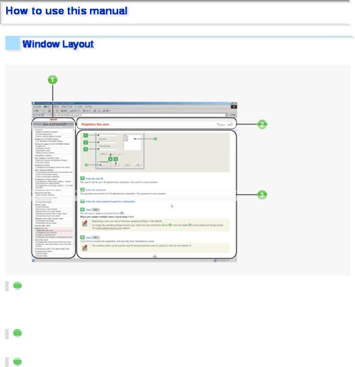
This manual consists of three resident windows:
1 INDEX window
This window shows a table of contents.
The headline of the topic currently opened at the main window is highlighted, so the current location among the manual can be easily confirmed.
2 TITLE window
This window shows the headline of the current topic. This TITLE window never scrolls not to hide the headline.
3 MAIN window
This window shows the main detail contents.
Copyright Notice/How to Use This Manual 5/8
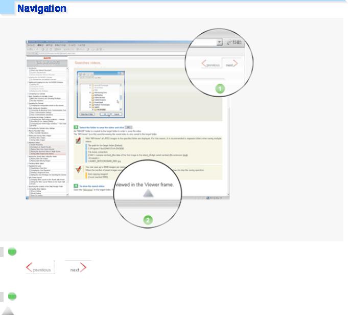
1 Previous/Next
Clicking or |
on the top right of the TITLE window will display the previous page or the next |
page, respectively.
2 Page end
 is located at the end of the page.
This mark is also linked to the top of the page. Click on this mark to jump to the top of the page.
Copyright Notice/How to Use This Manual 6/8

123 ...
Boxed numbers indicate procedural instructions.
1 2 3 ... A B C ...
Circled numbers or circled alphabetic letters are used in sections that describe screen component names or other information.
This manual uses the following three kinds of symbols depending on the content of the provided information.
Memo:
Indicates supplementary or related information.
Reference:
Provides references to the associated settings that must be configured on other menu screens.
Caution:
Indicates prohibited or restricted operating and setting instructions.
This manual uses the following notations to present user-interface related information:
Information such as the screen title is represented in all uppercase alphabetic letters, as displayed on the screen (Example: NETWORK SETTINGS).
Information such as operation buttons and icons are represented as graphics, as displayed on the screen (Example:  SET
SET  ).
).
The names of specific setting items, tabs, dialog boxes and the like are enclosed in square brackets [ ] (Example: [TITLE]).
Copyright Notice/How to Use This Manual 7/8

The options or values that you select in a pull-down menu or using radio buttons are enclosed in double quotes “ ” (Example: “ON”, “80”).
Each section describing a configuration procedure begins with a screenshot of the corresponding initial configuration screen.
The purpose of this screenshot is to show you the factory default value for each setting item provided on the screen.
Copyright Notice/How to Use This Manual 8/8

VCC-HD2500/HD2500P
Accessing the Camera
Control Panel/Tool Panel
CAMERA SETTINGS
Displaying LIVE video
Transmitting Image Data
Recording
Others
Q&A1/11
I cannot access the camera.
1 The camera IP address you entered is wrong.
 Enter the correct IP address (URL) in the Web browser (Internet Explorer).
2 The camera port number you entered is wrong.
 If you are using a port number other than 80, enter the correct port number in the Web browser (Internet Explorer).
3 Your have accessed with “http://” where you should be using HTTPS.
 When using HTTPS, access with “https://”. Also make sure to enter the port number if you have changed it to other than 443.
4 Access is restricted by security setting (The error message “403 forbidden” is displayed).  Contact your network administrator and ask him/her to change the security settings.
I cannot access the camera from within my home/company network.
1 The PC and camera IP addresses (local addresses) are configured with different subnet masks.  To use a PC and a camera within the same network, their subnet masks must be the same.
Change settings so that the PC and camera have the same subnet mask.
2 The Web browser you are using is configured to connect to the Internet via proxy server.  Change the Web browser settings so that the use of proxy server is disabled.
3 The address you are trying to access is not a local address.
 Enter a local address to access a camera located in the same network.
 You cannot access a camera by entering a URL (or router global address and camera port number) registered with the dynamic DNS service or a URL that is compliant with the global address.
I cannot access the camera from the Internet.
1 There is a wrong network setting in the camera.
 Configure the default gateway correctly. When using the dynamic DNS service, check whether the entered DNS server address and domain name registered with the dynamic DNS service are correct.
2 Registration to the dynamic DNS service is yet to be done. (When using the dynamic DNS service)  Go to the dynamic DNS service site and check that the address for your camera is correctly
registered.
3 Port forwarding is not configured on your router.
 Port forwarding must be configured on your router for you to be able to access a camera from the Internet. For the configuration method, refer to your router's instruction manual.
Q&A 2/11
4 Your router is configured with packet filtering or the like which restricts access from the Internet.  Change the settings in your router to allow access from the Internet. For the configuration method,
refer to your router's instruction manual.
5 The IP address you entered is a local address (the one you use at your home).
 When accessing via Internet, enter the global address (or the URL registered with the DDNS service) and port number of the camera as its IP address.
The camera has been suddenly disconnected.
1 Another user has changed the password.  Configure the password settings again.
2 Another user has changed the camera settings.  Access again after a while.
I get stuck at the Login screen.
 The password is changed.
 Check the password and try again.
The access lamp does not go on.
1 The LAN cable that connects directly to the camera is broken.  Connect the LAN cable.
2 The LAN cable has been unplugged.  Connect the LAN cable.
3 The switching hub is turned off.  Turn on the switching hub.
I forgot the camera IP address/port number.
 Press the SET button provided on the left-side face of the camera and, on the SELECT MENU screen, select [FIRMWARE VERSION] to check the firmware version.
 Using the supplied “Auto IP Setup” software, execute a camera search.
Q&A 3/11

Buttons on the control panel/tool panel do not respond.
1 You do not have the required operation privilege.
 Some buttons on the control panel/tool panel are operable only when you have an adequate operation privilege. Log in as a user with an adequate operation privilege.
2 You have not configured the required operation settings.
 The audio controls on the tool panel are operable only when you have configured the audio settings on the CLIENT SETTINGS screen.
 The [DIGITAL PTZ] button is not operable when you have set [DIGITAL PTZ] to “OFF” on the VIDEO & AUDIO SETTINGS screen.
 The Remote Alarm buttons are operable only when you have set [ALARM OUT 1/2] to “REMOTE” on the ALARM SETTINGS screen.
The [MENU] button does not respond.
 Only the admin and operator1 users have the operation privilege for the configuration screens.
 Without the required operation privilege, you will be presented with an authentication check dialog box when you click the [MENU] button on the live screen.
In this case, you can change the operation privilege by entering a user name with an adequate operation privilege and its password in the dialog box.
Q&A 4/11
I cannot set [SENSE UP] in [IRIS].
 You cannot set [SENSE UP] when [SHUTTER] is set to “SHORT” or “LONG”.
  Set [SHUTTER] to “OFF”.
I cannot set [SHUTTER] to “SHORT” or “LONG”.
 You cannot configure the electronic shutter settings if you have set [SENSE UP] in [IRIS].
 Set [SENSE UP] in [IRIS] to “OFF”.
I cannot turn off the AGC.
1 You cannot set [AGC] to “OFF” when [DAY/NIGHT] is set to “AUTO”.  Set [DAY/NIGHT] to “COLOR” or “B/W”.
2 You cannot set [AGC] to “OFF” when [SENSE UP] in [IRIS] is set to “ON”.  Set [SENSE UP] in [IRIS] to “OFF”.
Q&A 5/11
I cannot display LIVE video.
1 ActiveX control is not installed in your PC.  Install ActiveX.
2 There is network congestion.
 It may take some time until the screen can be displayed. Please wait.
 The message “THE UNIT IS BUSY” appears on the screen if the number of simultaneously accessible users is already reached.
3 The version of the installed ActiveX control is old.
 When another ActiveX control for network cameras is installed, video may not be displayed due to compatibility issues between the different versions. Install the H.264 Plug-In included in the supplied CD-ROM or the latest H.264 Plug-In you can download from SANYO CCTV System Web page.
4 The Web browser you are using for accessing the camera is configured to connect to the Internet via proxy server.
 Some proxy servers block UDPs during H.264 browsing. In this case, either change the settings to browse H.264 using HTTP, or browse using JPEG.
I cannot install the “H.264 Plug-In” included in the supplied CD-ROM.
1 The OS of your PC is not a recommended OS.
 The OS must be Windows Vista, Windows XP Home Edition or Windows XP Professional SP2 or later for the H.264 Plug-In to run.
2 You are not logged into the PC with administrator privileges.
 To install the H.264 Plug-In in a PC, you need OS administrator privileges. If you are logged in with user privileges, log out and log in again with administrator privileges to do the installation.
An error code appears and no LIVE video is displayed.
1 The configured IP address or domain name is wrong.  Configure the IP address or domain name correctly.
2 If the address or domain name is correct, then the network connection has timed out.
 Use the network when it is not congested, or check whether there are other applications using the network and if there are, stop them for example.
The screen has suddenly stopped refreshing.
 A camera power or network fault has occurred.
Q&A 6/11
 Check the power supply status and/or the network environment.
The video image is distorted and cannot be displayed correctly.
1The maximum bit rate for video streaming is configured with a value higher than the network bandwidth.
 Lower the resolution and/or image quality.
2The performance of the PC is low.
 Make sure that your PC meets the operation requirements specified in the “Operating Environment” section.
Or replace the video card in the PC with another with higher performance.
The image quality is bad.
 The color quality for your PC monitor is configured to less than 16 bits.
 On the [Display Properties] -[Settings] tab, configure the [Color quality] setting for your PC to 16 bits or more.
The recording rate is low or the video stops temporarily.
1 Among the multiple accesses to the camera, some are from narrowband networks.  Change the minimum bit rate for video streaming to a large value.
2 There are multiple accesses or accesses with request for multiple resolutions.
 Increasing the number of accesses or simultaneous streamings with different resolutions may decrease the recording rate and/or image quality. Lower the resolution, image quality, and/or recording rate.
The recording rate is low at maximum resolution.
 The performance of the PC is low.
 Make sure that your PC meets the operation requirements specified in the “Operating Environment” section.
Or replace the video card in the PC with another with higher performance.
The LIVE video image is not clear.
1 The camera focus has not been adjusted to the correct position.
 Click [FOCUS ASSIST] on the CAMERA SETTINGS screen and readjust the camera focus using the focus assist function.
2 The object is too close to the camera.  Move away the object from the camera.
Q&A 7/11

3 Dust, dirt, fingerprints, etc. are present on the lens cover. Or the lens is fogged.  Wipe away the dust, etc. with a dry cloth.
The live video display is entirely discolored (A white subject appears to be colored.)
 Adjust the white balance.
 Click [WHITE BALANCE] on the CAMERA SETTINGS screen and, in [WHITE BALANCE], select “MWB”. Then, adjust the white balance so that a white subject appears to be white.
The LIVE video image is noisy.
1 The background of the object is dark.
 Increase the lighting to the monitored environment.
Alternatively, click [DAY/NIGHT] on the CAMERA SETTINGS screen and set [DAY/NIGHT] to “AUTO” to enable the Day/Night function.
2 The color quality for your PC monitor is configured to less than 16 bits.
 On the [Display Properties] -[Settings] tab, configure the [Color quality] setting for your PC to 16 bits or more.
The image contains white spots or colored light spots.
 You are using the camera in a dark place. Or, you are recording a dark object.
 White spots or colored light spots may appear on the screen when the camera is used in a dark place or monitoring a dark subject. This is a characteristic of the image pickup device and is not a malfunction. Use auxiliary lighting or some other means to illuminate the monitored environment.
Q&A 8/11
The e-mail transmission function does not work.
1On the E-MAIL SETTING screen, incorrect user ID/password information is specified in the AUTHENTICATION section.
 Set the correct login ID and password.
2The server address is wrong. Or connection to the server is down.
 Check the server address settings.
3 The SMTP server requires authentification.
 If [AUTHENTICATION] is set to “NO USE”, the e-mail transmission function does not work when the SMTP server requires authentification. Contact your network administrator and change the authentication setting according to the SMTP server setting.
This camera supports the two authentication methods, “SMTP” and “POP3 (POP before SMTP)”.
4 Transfer is blocked by the “Outbound Port 25 Blocking (OP25B)” implemented by your provider.  Select the SMTP authentication for the camera and change the destination e-mail server port from
25 to 587.
 Use the destination e-mail server of your provider.
I cannot view the image data I received on my cell phone.
 Some cell phones have a limit on the size of image data they can handle.
 Check the resolution of your cell phone.
Q&A 9/11

The camera does not record.
1 No SD memory card has not been installed in the camera.  Install an SD memory card.
2 The SD memory card has not been formatted.
 Format the SD memory card on the SD MEMORY CARD screen.
3 Time elapsed from turning on the camera is less than 5 minutes.
 After turning on the camera, wait 5 minutes or more before starting to record.
4 The SD memory card is write-protected.
 Release the write-protection switch on the SD memory card.
5 You may have removed the SD memory card without first stopping the data write.
 Format the SD memory card. Furthermore, the SD memory card may be damaged if you remove it while it is being accessed. Before removing an SD memory card, stop recording by proceeding as follows.
<Method for stop recording>
Set [SD MEMORY CARD] to “NO USE” on the SD MEMORY CARD screen.
Or, press the NEAR button provided on the left-side face of the camera for 2 seconds or more.
I cannot play back.
 The camera is not equipped with playback functions.
 Install the supplied application software “HDC Downloader/ DLViewer” from the supplied CD-ROM. This application software will allow you to download and play back video data.
Q&A 10/11
Upgrade has been terminated.
 Upgrade has been interrupted due to power off, network fault, or other problem during the process.
 Redo the upgrade by proceeding as follows.
1 Turn on the camera again.
2 Access the camera again.
3 Check the firmware version on [FIRMWARE UPDATE] in OPTION SETTINGS screen.
*If the version number is updated: Upgrade is complete.
*If the version number is not updated: Redo the upgrade.
The date and time is not adjusted automatically by the NTP server.
1 The GATEWAY settings are not configured correctly.
 Select NETWORK and configure the [GATEWAY] settings again.
2 The NTP server address is not configured correctly.
 Select CLOCK and configure the [NTP SERVER ADDRESS] settings again.
3 Adjustment by NTP is not set as the method for automatic time adjustment.  Select CLOCK and set [CLOCK ADJUST] to [ON (NTP)].
The date and time information indicated on the live screen does not reflect the clock settings configured on the [CLOCK SETTINGS] screen.
 It is recommended that you delete temporary Internet files.
 To do so, in Internet Explorer, click [Internet Options] in the [Tools] menu and then delete temporary files, history, cookies, saved passwords, and web form information from the [General] tab.
Q&A 11/11
VCC-HD2500/HD2500P
NETWORK SETTINGS
CLOCK SETTINGS
USER REGISTRATION
VIDEO & AUDIO SETTINGS
CAMERA SETTINGS
ALARM SETTINGS
RECORDING
SD MEMORY CARD
E-MAIL SETTINGS
FTP SETTINGS
SECURITY SETTINGS
SCHEDULE SETTINGS
OPTION SETTINGS
Working with Administrator Configuration Screens1/66
Click  NETWORK
  in the configuration menu to display the NETWORK SETTINGS screen. On this screen, configure the following settings as required.
AConfiguring basic network settings (NETWORK)
BConfiguring DDNS setting (DDNS)
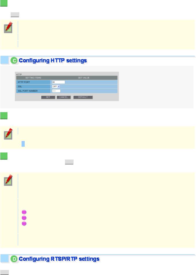
CConfiguring HTTP settings
DConfiguring RTSP/RTP settings
EConfiguring access name settings (ACCESS NAME)
FMulticast settings (MULTICAST)
Required operation privilege: admin
Before attempting to configure these network settings, contact your network administrator.
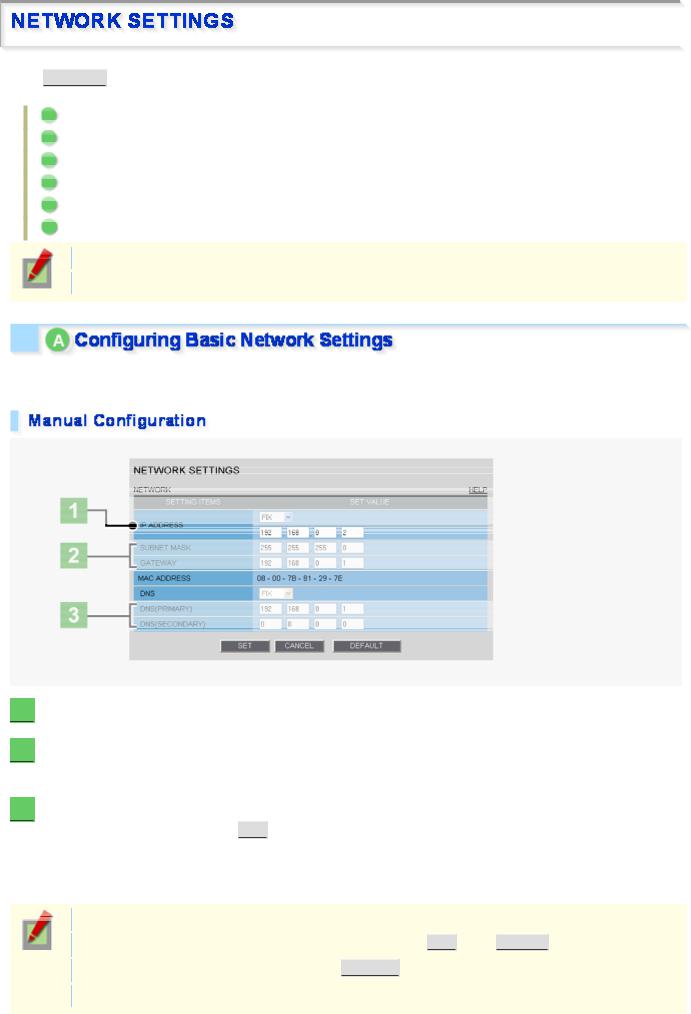
Configure the environment required to connect to the camera via the network by specifying the IP address, subnet mask, and other information.
1  In [IP ADDRESS], select “FIX” and type the IP address of the camera below it.
2  In [SUBNET MASK] and [GATEWAY], type your subnet mask and gateway addresses, respectively.
3  In [DNS (PRIMARY)] and [DNS (SECONDARY)], type your primary and secondary DNS server addresses and click
  SET
SET  .
.
Because you selected “FIX” in [IP ADDRESS], you specify here fixed DNS server addresses.
After completing the above steps, click the Close button to once disconnect and then reconnect to the camera to apply the changes.
To redo the procedure from the beginning, before clicking  SET
SET  , click
  CANCEL
  .
.
To restore the factory default settings, click  DEFAULT
  .
.
In [MAC ADDRESS], the MAC address of the camera is shown. You cannot change this address.
Working with Administrator Configuration Screens 2/66
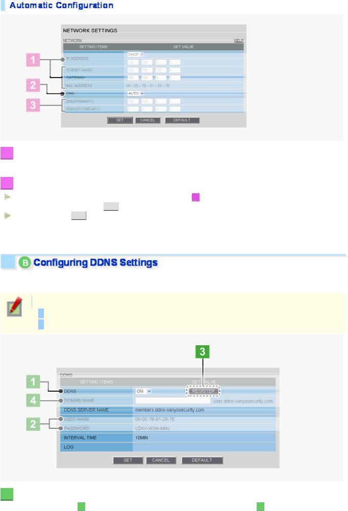
1  In [IP ADDRESS], select “DHCP”.
The IP address, subnet mask, and gateway fields are automatically filled.
2  In [DNS], specify how you want to configure the DNS server addresses.
FIX: In [DNS (PRIMARY)] and [DNS (SECONDARY)] ( 3 ), type your primary and secondary DNS server addresses and click
  SET
SET  .
.
AUTO: Just click SET . Then, the system sets appropriate DNS server addresses automatically.
After completing the above steps, click the Close button to once disconnect and then reconnect to the camera to apply the changes.
Using SANYO's DDNS service, you can connect to the camera from your Internet Explorer by simply entering the registered domain name, instead of the IP address of the camera.
To use the DDNS service, configure the following settings.
Specify your DNS server address under [DNS SETTINGS] on this screen.
Configure the port forwarding on your router. (For details, refer to your router's instruction manual.)
1  In [DDNS], select “ON”.
The [REGISTER] button ( 3 ) appears. The [USER NAME] and [PASSWORD] fields ( 2
 ) show the automatically assigned user name and password, respectively.
Working with Administrator Configuration Screens 3/66
2  Write down the user name and password shown in the [USER NAME] and [PASSWORD] fields.
This information is required to register your domain name.
3  Click
Click  REGISTER
  to access the SANYO DDNS service site and register your domain name.
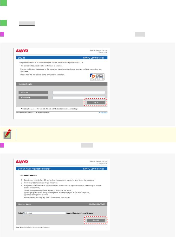
Follow the steps below to register your domain name.
1 On the LOG IN screen, enter the user name and password you wrote down and click
  Login
Login  . The Domain Name registration/change screen appears.
SANYO DDNS service site URL: https://www.ddns-sanyosecurity.com
2 Enter the domain name you want to use and click
  Submit
  . The domain name is registered with the DDNS server.
Working with Administrator Configuration Screens 4/66
4  Return to the NETWORK SETTINGS screen ([DDNS]) and, in [DOMAIN NAME], type the domain name you just registered before “.user.ddns-sanyosecurity.com”. Then, click
 SET
SET  .
.
The [DDNS SERVER NAME] field is automatically filled (“members.ddns-sanyosecurity.com”), so you do not need to type it.
The [INTERVAL TIME] setting (access interval to the server) is fixed to “10” (10 minutes). In the [LOG] field, the DDNS update history log (one entry) is shown.
1  In [HTTP PORT], type your HTTP port number.
Type a number between 1 and 65535.
The default port number depends on whether or not you enable SSL communication in [SSL].  When [SSL] is set to “OFF”: 80
When [SSL] is set to “ON”: 443
2  To use SSL communication, select “ON” in [SSL], type your SSL port number in [SSL PORT NUMBER], and click
  SET
SET  .
.
Using SSL communication enables the encryption of image transmission. SSL communication is effective for JPEG streaming images only.
When SSL communication is enabled, you will be presented with a security warning dialog box when attempting to access the camera. However, this is not a problem and you can continue the operation by clicking [Yes].
If the message “This page contains both secure and nonsecure items...” appears, follow the steps below to erase it.
1In Internet Explorer, click [Internet Options] in the [Tool] menu.
2On the [Security] tab, click the [Custom Level...] button.
3In the [Security Settings] dialog box, in the [Settings] section, select the “Display mixed content” radio button.
When SSL communication is enabled, the frame rate of the live streaming images may become slower depending on the resolution setting.
In [RTSP PORT], [RTP PORT (VIDEO)], and [RTP PORT (AUDIO)], type the desired port numbers and click
 SET
SET  .
.
Working with Administrator Configuration Screens 5/66
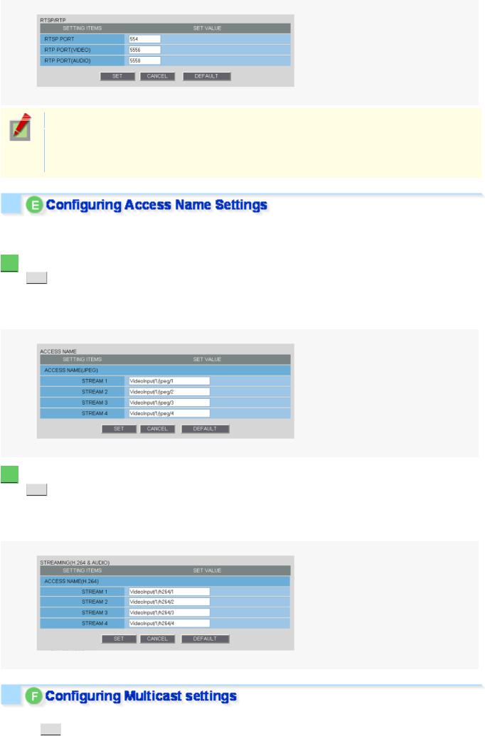
The RTSP port number must be 554 or otherwise a number in the range of 1 to 65535.
The RTP port (video and audio) numbers must be even numbers in the range of 1026 to 65534 (except for numbers between 3874 and 5000, between 9874 and 10000, between 38087 and 38214, and between 49026 and 49152).
If you intend to access the camera from video viewer or similar software, you may name each stream (access name) as you like for easy identification.
1  Under [ACCESS NAME (JPEG)], type an access name for each JPEG stream and click
SET .
These settings are used for each stream for which you set the codec to “JPEG” on the VIDEO & AUDIO SETTINGS screen.
An access name must be specified for each stream (up to 32 alphanumeric characters).
2  Under [ACCESS NAME (H.264)], type an access name for each H.264 stream and click
SET .
These settings are used for each stream for which you set the codec to “H.264” on the VIDEO & AUDIO SETTINGS screen.
An access name must be specified for each stream (up to 32 alphanumeric characters).
To enable multicast streaming, configure the multicast address, port numbers, and TTL settings for each stream and click  SET
SET .
.
Working with Administrator Configuration Screens 6/66
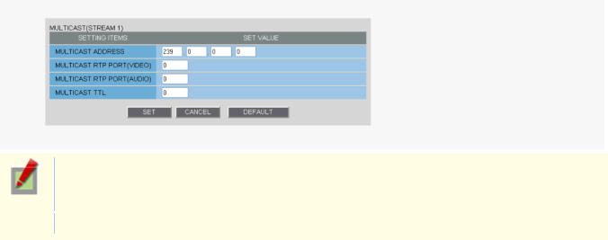
The multicast RTP port (video and audio) numbers must be even numbers in the range of 1026 to 65534 that do not overlap with the unicast RTP port numbers
(except for numbers between 4000 and 5000, 10000, 10001, 38214, and 49152.)
The multicast TTL must be specified in the range of 1 to 255.
Working with Administrator Configuration Screens 7/66
Click  CLOCK
CLOCK  in the configuration menu to display the CLOCK SETTINGS screen.
Before you start network operation, you need to configure the clock settings on this screen.
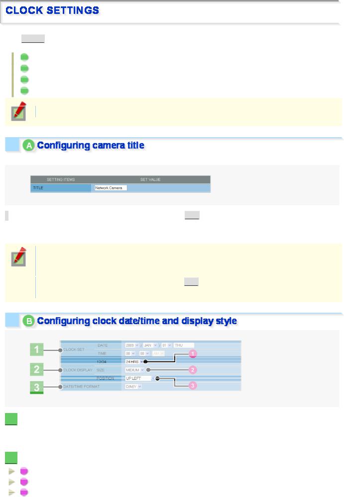
AConfiguring camera title
BConfiguring clock date/time and display style
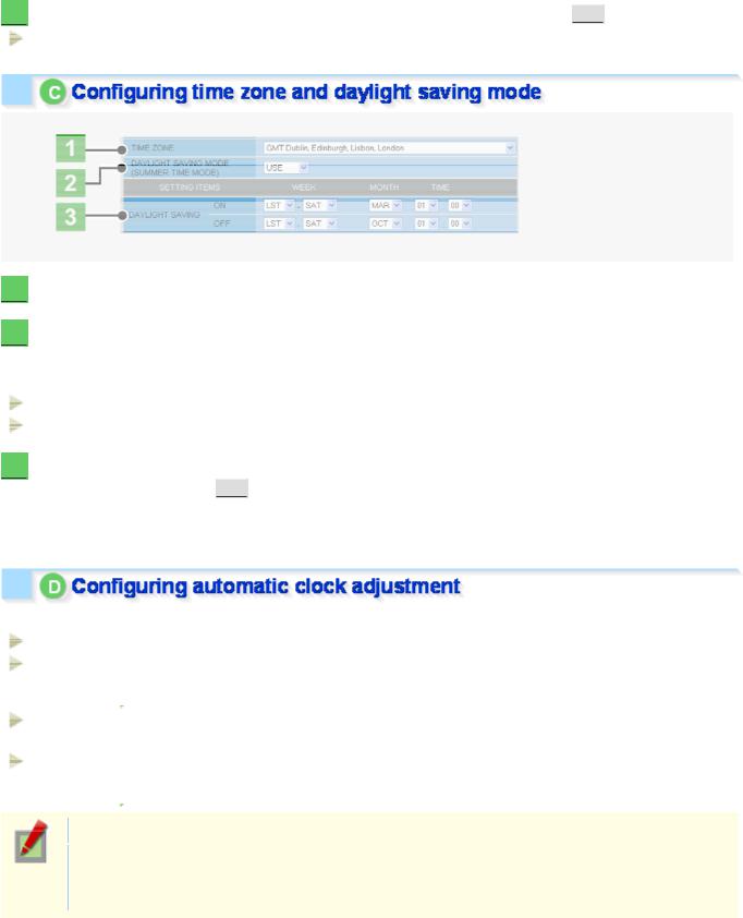
CConfiguring time zone and daylight saving mode
DConfiguring automatic clock adjustment
Required operation privilege: admin, operator1
Configure the camera title that will be displayed on the live screen and in e-mails, image files, and so on.
In [TITLE], type the desired camera title and click  SET
SET  .
.
You can type up to 16 alphanumeric characters.
The setting is saved and the camera title appears on the live screen.
Note that the camera title cannot include the following symbols: double quote ("), single quote ('), ampersand (&), greater-than sign (<), percent (%), backslash (\), less-than sign (>), vertical bar (|), and semicolon (;).
A warning dialog box will appear when you click  SET
SET  if the camera title includes any invalid character.
1  In [CLOCK SET], configure the current date and time in [DATE] and [TIME], respectively.
The configured date and time settings will be reflected on the camera's built-in clock. The day of the week is automatically set based on the date and time settings.
2  In [CLOCK DISPLAY], select the clock display style.
1 |
12/24 (Clock type): |
12HRS (12-hour clock), 24HRS (24-hour clock) |
2 |
SIZE (Character size): |
SMALL, MEDIUM, LARGE |
3 |
POSITION (Display position): |
UP LEFT, UP RIGHT, DOWN LEFT, DOWN RIGHT, OFF (Hidden) |
Working with Administrator Configuration Screens 8/66
3  In [DATE/TIME FORMAT], select the date/time display format and click
  SET
SET  .
.
M/D/Y, Y/M/D, D/M/Y
1  In [TIME ZONE], select the region where the camera is used.
2  In [DAYLIGHT SAVING MODE], select whether or not to use the daylight saving mode.
Although an appropriate setting is automatically selected according to the [TIME ZONE] setting, you can change it manually.
NO USE: Disables the daylight saving mode.
USE: Enables the daylight saving mode.
3  In [DAYLIGHT SAVING], select when to start (in [ON]) and end (in [OFF]) the daylight saving mode and click
  SET
SET  .
.
Although an appropriate setting is automatically selected according to the [TIME ZONE] setting, you can change it manually.
In [CLOCK ADJUST], select how you want to automatically adjust the camera's internal clock.
OFF: Disables the clock adjustment function.
ON (NTP): Enables automatic clock adjustment that retrieves the date and time information from the NTP server.
 You need to configure the NTP settings.
LOGIN Enables automatic clock adjustment that retrieves the date and time information from the PC (PC): when an admin user logs into it.
ALARM Enables automatic clock adjustment that adjusts the clock to the specified time based on the IN1: signal received from the device connected to the ALARM IN1 terminal.
 You need to configure the [CLOCK IN] setting.
It is recommended to select “ON (NTP)” when the camera is connected to the Internet.
If the camera is not connected to the Internet, select “LOGIN (PC)” or, using the supplied monitoring software “VA-SW3050Lite”, enable the clock adjustment function (24-hour interval) in the clock setting.
Working with Administrator Configuration Screens 9/66
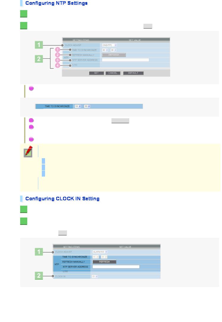
1  In [CLOCK ADJUST], select “ON (NTP)”.
2  Configure the required settings shown below and click
  SET
SET  .
.
1To automatically adjust the clock time every day, in [TIME TO SYNCHRONIZE], select the 24-hour time to which you want to adjust the clock (for example, “10:30”).
2To adjust the clock to the current time, click  REFRESH
  .
.
3In [NTP SERVER ADDRESS], type the IP address or domain name of the NTP server from which you want to retrieve the date and time information.
4In [LOG], the last entry of the operation log related to automatic clock adjustment is shown.
When “ON (NTP)” in [CLOCK ADJUST] is selected, the clock adjustment function adjusts the clock in the following timings.
When the camera is turned on
At the time selected in [TIME TO SYNCHRONIZE] (every day)
When any change is made to the settings on this screen
To use a domain name, you must specify the DNS server address in [DNS SERVER ADDRESS] on the NETWORK SETTINGS screen.
1  In [CLOCK ADJUST], select “ALARM IN1”.
2  In [CLOCK IN], select the 24-hour time to which you want to adjust the clock (for example, “22” for 10 p.m.) when the switch connected to the ALARM IN1 terminal turns on, and click
  SET
SET .
.
Working with Administrator Configuration Screens 10/66
 Loading...