


INSTRUCTION MANUAL
Color CCD Camera
THIS INSTALLATION SHOULD BE MADE BY A QUALIFIED SERVICE PERSON AND SHOULD CONFORM TO ALL LOCAL CODES.
VCC-N6584 VCC-N6695P VCC-N4598PC
Deutsch Español Français English
Please read this instruction manual carefully in order to ensure correct installation. In addition, be sure to read carefully the electronic manual contained in the supplied CD-ROM to ensure correct operation of the camera.
This manual covers 3 models. Any difference between the 3 models is indicated when necessary.

Contents |
|
Information to User...................................................................................................... |
2 |
Preparations ................................................................................................................ |
4 |
Parts Names and Functions ........................................................................................ |
5 |
Viewing Live Images on a Monitor (Basic Connections) ............................................. |
6 |
Camera Settings.......................................................................................................... |
7 |
Viewing Live Images on a Computer (Network Connection) ....................................... |
9 |
Network Settings ....................................................................................................... |
12 |
Setting the Camera from the Computer..................................................................... |
14 |
Using the Supplied CD-ROM..................................................................................... |
16 |
Specifications ............................................................................................................ |
17 |
■ Check the operating environment
• PC |
: IBM PC/AT and compatibles |
• OS |
: Windows Vista/Windows XP Professional Edition SP2 |
• CPU |
: Pentium IV (2.0 GHz or higher) |
|
3.0 GHz or higher for using the VA-SW3050LITE |
• Memory |
: 1 GB or more (2 GB or more for using Vista) |
•Network interface : 100Base-TX (RJ-45 connector)
•Graphics processor : GeForce 6000 series or higher
• |
Display card |
: |
1024 x 768 pixels or higher, 16 million colors or higher |
• |
Web browser |
: |
Internet Explorer Ver. 6.0 or higher |
1

Information to User
Safety Guard
CAUTION |
RISK OF ELECTRIC SHOCK |
DO NOT OPEN |
CAUTION: TO REDUCE THE RISK OF ELECTRIC SHOCK, DO NOT REMOVE COVER (OR BACK).
NO USER-SERVICEABLE PARTS INSIDE. REFER SERVICING TO QUALIFIED SERVICE PERSONNEL.
The lightning flash with arrowhead symbol, within an equilateral triangle, is intended to alert the user to the presence of uninsulated “dangerous voltage” within the product’s enclosure that may be of sufficient magnitude to constitute a risk of electric shock to persons.
The exclamation point within an equilateral triangle is intended to alert the user to the presence of important operating and maintenance (servicing) instructions in the literature accompanying the product.
CAUTION: Changes or modifications not expressly approved by the manufacturer may void the user’s authority to operate this equipment.
This equipment has been tested and found to comply with the limits for a Class B digital device, pursuant to Part 15 of the FCC Rules.
These limits are designed to provide reasonable protection against harmful interference in a residential installation. This equipment generates, uses and can radiate radio frequency energy and, if not installed and used in accordance with the instructions, may cause harmful interference to radio communications.
However, there is no guarantee that interference will not occur in a particular installation.
If this equipment does cause harmful interference to radio or television reception, which can be determined by turning the equipment off and
on, the user is encouraged to try to correct the interference by one or more of the following measures.
•Reorient or relocate the receiving antenna.
•Increase the separation between the equipment and receiver.
•Connect the equipment into an outlet on a circuit different from that to which the receiver is connected.
•Consult the dealer or an experienced radio/TV technician for help.
WARNING: To reduce a risk of fire or electric shock, do not expose this appliance to rain or moisture.
■ For Russian Users
This product certified by official certification company which is authorized by Russian Federation.
 ДЛЯ ПОЛЬЗОВАТЕЛЕЙ РОССИЯ
Данная продукция сертифицирована официальным органом по
сертификации Российской Федерации.
For the customers in Canada
This class B digital apparatus complies with Canadian ICES/NMB-003.
2
Information To User
For EU Users
Please note:
Your SANYO product is designed and manufactured with high quality materials and components which can be recycled and reused.
This symbol means that electrical and electronic equipment, at their end-of-life, should be disposed of separately from your household waste.
Please dispose of this equipment at your local community waste collection/recycling centre. In the European Union there are separate collection systems for used electrical and electronic products.
Please help us to conserve the environment we live in!
This symbol mark and recycle system are applied only to EU countries and not applied to the countries in the other area of the world.
SANYO FISHER Sales (Europe) GmbH
Stahlgruberring 4, D-81829 München, Germany
SANYO Electric Co., Ltd.
1-1, Sanyo-cho, Daito City, Osaka 574-8534, Japan
Precautions
■ In case of a problem |
■ Protect from humidity and dust |
Do not use the unit if smoke or a strange odor comes from the unit, or if it seems not to function correctly. Turn off the power immediately and disconnect the power cord, and then consult your dealer or an Authorized Sanyo Service Center.
■ Do not open or modify
Do not open the cabinet, as it may be dangerous and cause damage to the unit. For repairs, consult your dealer or an Authorized Sanyo Service Center.
■ Be careful when handling the unit
To prevent damage, do not drop the unit or subject it to strong shock or vibration.
■Do not put objects inside the unit
Make sure that no metal objects or flammable substance get inside the unit. If used with a foreign object inside, it could cause a fire, a shortcircuit or damage. Be careful to protect the unit from rain, sea water, etc. If water or liquid gets inside the unit, turn off the power immediately and disconnect the power cord, and then consult your dealer or an Authorized Sanyo Service Center.
■Do not install this unit close to
magnetic fields
The magnetic fields may result in unstable operation.
To prevent damage, do not install the unit where there is greasy smoke or steam, where the humidity may get too high, or where there is a lot of dust.
■Protect from high temperatures
Do not install close to stoves, or other heat sources, such as spotlights, etc., or where it could be subject to direct sunlight, as this could cause deformation, discoloration or other damage.
Be careful when installing close to the ceiling, in a kitchen or boiler room, as the temperature may rise to high levels.
■Cleaning
•Dirt can be removed from the cabinet by wiping it with a soft cloth. To remove stains, wipe with a soft cloth moistened with a soft detergent solution and wrung dry, then dry by wiping with a soft cloth.
•Do not use benzine, thinner or other chemical products on the cabinet, as this may cause deformation and paint peeling. Before using a chemical cloth, make sure to read all accompanying instructions. Make sure that no plastic or rubber material comes into contact
with the cabinet for a long period of time, as this may cause damage or paint peeling.
3
Preparations
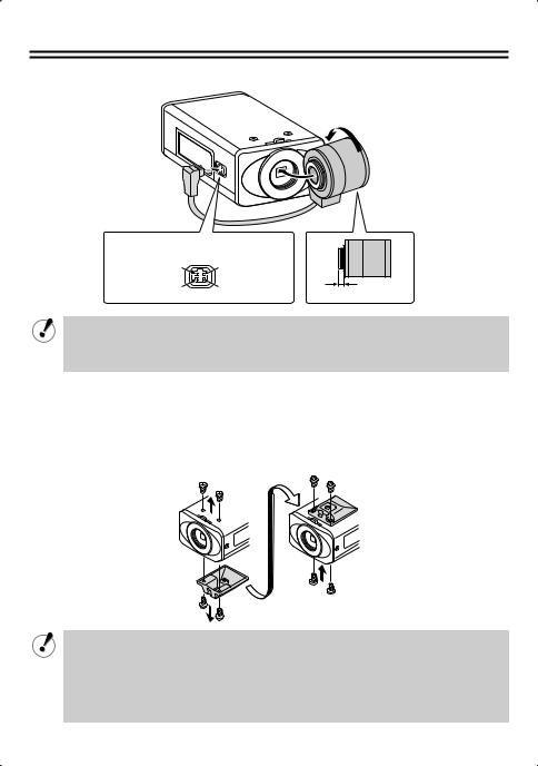
■ Installing the lens (for CS mount)
Lens terminals for auto iris lens
Brake coil (+) |
Brake coil (–) |
Drive coil (–) |
Drive coil (+) |
5 mm/0.2 in. or less
•If using a C mount lens, install a commercially-available adapter ring.
•The shape of the lens plug may not mach depending on the type of lens being used. If the shape does not match, contact the place of purchase or an authorized service agent.
■Installing the camera
The bracket can be installed either above or below as shown in the illustration.
When installing the camera, check whether the screws can be securely tightened or not. Plaster boards and similar will not provide enough strength, so use extra measures such as a reinforcement plate to securely tighten the screws.
•If monitoring objects which have a brightness that exceeds the maximum brightness amount for objects because of the degree of illumination, smearing (a phenomenon where vertical or horizontal striped lines appear in high-luminance areas of the object) may occur. Adjust the angle of the illumination while monitoring the object.
•Select a suitable camera mounting bracket (commercially-available) which is able to bear the full combined weight of the camera unit and the mounting bracket, and install it securely in a durable location.
4

Parts Names and Functions
■ Rear
POWER |
ALARM OUT |
|
|
VIDEO OUT ALARM IN |
|
||
-- AC24V -- DC12V |
|
||
|
COM |
|
|
LAN |
|
||
LINK |
|
||
GND |
|||
|
|
||
CLASS 2 WIRING |
|
|
|
|
|
|
|
Flange back fixing screw |
|
||
Flange back adjustment lever |
|
||
AC24V / DC12V terminals
Connect this terminal to the power supply.
•When the camera is turned on, the POWER lamp lights.
Power lamp
Lens terminals
VIDEO OUT connector (BNC type)
Used to output image signals. Connect to video equipment such as a monitor.
Control terminals
When connecting the cable, press and hold down the protrusion of the terminal, insert the cable into the terminal, and then release the protrusion.
•COM terminal (Earth terminal)
•ALARM IN terminal
Connect to a device such as an external alarm switch or an infrared sensor.
•ALARM OUT terminal
Used to connect to an external buzzer or lamp.
When an alarm is detected, the device connected to the terminal notifies that an alarm is detected.
LAN connector (RJ-45)
Used to connect the camera to your network.
LINK lamp
When connected correctly to the network, the lamp will illuminate 3 seconds after the power is turned on.
Flashes while data is being transferred.
■ Side


Camera setting switches (P7)
White balance manual adjustment controls
R: Red adjustment
B: Blue adjustment
Iris adjustment control (LEVEL)
This can only be adjusted when using a DCtype automatic iris lens.
Reset button (RESET)
If pressed for approximately 5 seconds, it initializes the various NETWORK SETTINGS settings (such as IP address) for network operations.
5
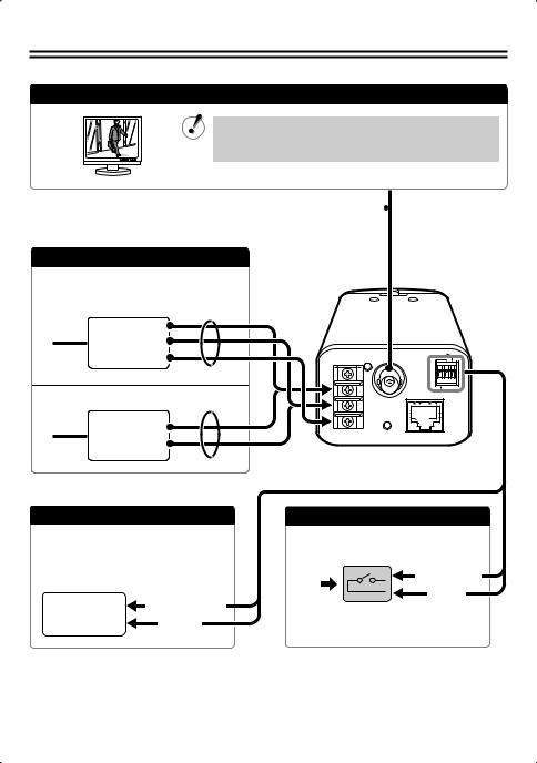
Viewing Live Images on a Monitor (Basic Connections)
All the power supplied to the system should be turned off when you connect devices.
Monitor Connection
Using different cables from those specified here may attenuate the video and/or sync signals and interfere with correct transmission.
Thicker than RG-6U (5C-2V): 500 m / 547 yds. max. 
(Non-PoE power supply)
Power Supply Connection
To prevent a fire hazard use any UL listed wire rated VW-1.
11
~
AC 24V ~
GND |
POWER |
VIDEO OUT |
ALARM OUT |
ALARM IN |
|||
-- DC12V |
-- AC24V |
|
|
Check that +/– polarity is correct. 11
+
DC 12V –
COM
LAN
LINK
GND
CLASS 2 WIRING
11 Thicker than 18 AWG |
Thicker than 24 AWG, 600 m / 656 yds. max. |
Alarm Signal Output
If a lamp is connected to this cable, it will light up when an alarm signal is received or when the built-in motion sensor detects movement.
External |
(ALARM OUT) |
|
peripheral |
||
(COM) |
||
equipment |
•To use the ALARM OUT setting, you must make the appropriate ALARM OUT settings for CAMERA SETTINGS in the network settings.
|
Alarm Signal Input |
|
Alarm |
(ALARM IN) |
|
input |
(COM) |
|
signal |
||
|
•To use the ALARM IN setting, you must make the appropriate ALARM IN settings for CAMERA SETTINGS in the network settings.
6

Camera Settings
This camera has been adjusted so that it can be used with a commercially-available DC-type auto iris lens. This may not be suitable for some operating conditions, and so use the switches and controls on the side to make adjustments if necessary.
• If correct adjustment cannot be obtained, contact the place of purchase.


|
|
|
The settings for this camera can be changed at the camera and using network operations (some settings may not apply). When changing settings, check the settings for “MAIN BODY SETTINGS” under “CAMERA SETTINGS” network operations.
• USE (initial setting): The switches and controls on the side of the camera can be used for adjustments.
• NO USE: Camera settings can be carried out via network settings.
■ Flange back adjustment
Normally adjustment is not necessary. If using a zoom lens and the images are out of focus, adjust the flange back by following the procedure given below.
|
Loosen the screw. |
|
Set to the telephoto position, and |
||
|
||
|
then use the lens focus ring to |
|
|
adjust the focus. |
|
|
Set to the wide-angle position, and |
|
then use the flange back adjustment |
||
|
||
lever to adjust the focus. |
||
|
Tighten the flange back fixing screw. |
|
|
Repeat steps and until there is no |
|
|
change in the focus when moving the lens |
|
|
from wide-angle to telephoto. |
7

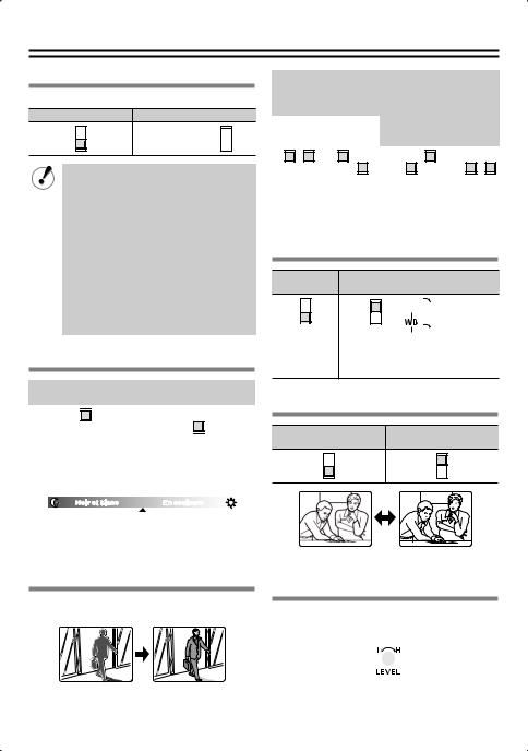
Iris setting (IRIS)
This sets the lens aperture.
Automatic iris (AI) |
Electronic iris (EI) |
||||
|
|
|
|
|
|
|
|
|
(For indoor use) |
|
|
|
|
|
|
|
|
|
|
|
|
|
|
|
|
|
|||
|
|
|
|
|
|
|
|
|
|
|
|
|
|
|
|
|
|
•When setting the electronic iris, set the lens aperture to maximum (minimum F value).
•If using an electronic iris (fixed or manual iris lens) under fluorescent light illumination, flickering may occur in the images.
•If the overall images become too dark or too light when using an automatic iris lens, use the lens iris volume (LEVEL) to adjust.
Day/night setting (D/N)
Automatic setting (ON) |
Color image fixed (OFF) |
||||
|
|
|
|
|
|
|
|
|
|
|
|
|
|
|
|
|
|
|
|
|
|
|
|
Automatic setting:
When it become dark, images are automatically switched from color images to black-and-white (non-IR sensitive) images.
Black-and-white |
Color |
Switching luminance
Color image fixed:
Images are always taken in color
Backlight compensation (BLC)
This is only enabled when using an automatic iris lens.
Multi-spot metering* |
Center-zone |
|
|
|
|
|
|||||||||||||
|
Applies backlight |
metering |
|
|
|
|
|
||||||||||||
|
compensation to the |
Applies backlight |
|
OFF |
|||||||||||||||
whole image (MULTI). |
compensation to |
|
|||||||||||||||||
|
|
|
|
|
|||||||||||||||
|
|
|
|
|
|
|
|
|
|
the center of the |
|
|
|
|
|
||||
|
High |
|
Normal |
|
|
|
|
|
|||||||||||
|
|
image (CENT). |
|
|
|
|
|
||||||||||||
|
|
|
|
|
|
|
|
|
|
|
|
|
|
|
|
|
|
|
|
|
|
|
|
|
|
|
|
|
|
|
|
|
|
|
|
|
|
|
|
|
|
|
|
|
|
|
|
|
|
|
|
|
|
|
|
|
|
|
|
|
|
|
|
|
|
|
|
|
|
|
|
|
|
|
|
|
|
|
|
*If the background for the objects is extremely dark, set to center-zone metering.
*If you would like compensation for the overall image to be carried out quickly, select high.
White balance (WB)
Automatic
Manual (MANU)
(ATW)


 (Red)
(Red)

 (Blue)
When turned clockwise, the hue becomes higher.
Aperture compensation (AP)
Normal outline
Sharper outline (HI)
(NORM AP)
Lens iris level adjustment (LEVEL)
Adjust if the overall images are too dark or too bright when using an automatic iris lens.
(Darker)  (Brighter)
8

Viewing Live Images on a Computer (Network Connection)
■Connection when Using PoE (Power over Ethernet) Power Supply
•Do not use the power supply of the camera.
•Do not supply power to the PoE hub or PoE power adapter until the camera installation is finished.
AConnect the camera to the LAN through a switching hub using shielded LAN cables.
You may extend the transmission distance by using multiple switching hubs with PoE support.
For details on the extendable distance, please refer to the hub performance in the specifications, etc.
Switching hub |
PC |
with PoE support |
|
Monitor |
11 |
11
ALARM OUT
POWER VIDEO OUT ALARM IN DC12V-- AC24V-- 


COM
LAN
LINK
GND
CLASS 2 WIRING
BConnect the camera to the LAN through a power adapter and a switching hub using shielded LAN cables.
Power adapter
11
|
|
|
|
|
|
|
11 |
|
PC |
||
|
|
|
|
|
|
|
|
|
|
|
|
|
|
|
|
|
|
|
|
|
|
|
|
11
Switching hub
1: LAN cable: CAT5 or higher, straight type, Max. 100 m / 109 yds
9
■ Connection when Not Using PoE (Power over Ethernet) Power Supply
|
A Internet connection (P11) |
|
|
Router or |
PC |
LAN cable |
|
|
ADSL modem |
|
|
(straight type) |
|
|
11 |
11 |
|
B Direct connection
Monitor
PC
LAN cable (crossover type)
ALARM OUT
-- AC24V -- DC12V |
POWER VIDEO OUT ALARM IN |
|
|
|
COM |
|
LAN |
GND |
LINK |
|
|
CLASS 2 WIRING |
|
|
C LAN connection |
|
|
Power Supply |
LAN cable |
|
PC |
(straight type) |
|
||
(AC24V/DC12V) |
|
||
|
|
|
|
|
11 |
|
|
|
Switching hub |
11 |
|
|
|
|
|
|
1: LAN cable: CAT5 or higher, straight type, 100 m / 109 yds max. |
||
10

Viewing Live Images on a Computer (Network Connection)
■ About the “A Internet connection”
Port forwarding settings will need to be carried out for the image port (HTTP/UDP) of the broadband router.
•Port 1: JPEG/H.264 HTTP
Port number: Initial value 80 (TCP) IP address: Initial value 192.168.0.2
Port number: Initial value 80 (TCP)
• Set to match the LAN
To LAN port |
To WAN port |
|
|
|
|
|
|
|
|
|
|
Router
•Port 2: H.264 UDP Unicast
Port number: Initial value 3939 (UDP) IP address: Initial value 192.168.0.2
Port number: Initial value 3939 (UDP)
• Set to match the LAN
To LAN port |
To WAN port |
|
|
|
|
|
|
|
|
|
|
Router
•If UDP port forwarding has been set when viewing H.264 movie images over the Internet, the transfer can take place using the UDP protocol. However, it depends on the network environment, so ask your network administrator.
•For details on how to set port forwarding, please refer to your router’s Instruction manual.
MEMO:
When setting multiple cameras, use the network operations to set the port numbers for ports 1 and 2 to numbers which are different from the first camera.
•Port 1: [NETWORK] → “PORT NUMBER”
•Port 2: [CODEC/STREAMING] → “UDP (Unicast) PORT”
11

Network Settings
1 Network Settings
Set the TCP/IP settings in accordance with the operating system of the computer being used.
The screens below explain the procedure when using Windows Vista.
If using Windows XP, click [Start] → [Control Panel] → [Network & Internet Connections], and then click [Network Connections], and then proceed to step 3.
1 Click [Start] → [Control Panel] →
[Network and Sharing Center], and then click [Network Connections].
2 Click [Manage Network Connections].
3 Right-click the icon for the LAN card
(Ethernet adapter) you are using, and then select “Properties” from the menu.
If accessing the camera via UPnP (Universal Plug and Play), check the electronic manual on the included CD-ROM.
4 In “This connection uses the following items”, select “Internet Protocol Version 4 (TCP/IPv4)”, and then click Properties.
•For Windows XP, select “Internet protocol (TCP/IP)”.
5 Select “Use the following IP address”, and then enter the IP address, subnet mask and gateway.
If the camera’s IP address is the default address (192.168.0.2), enter “192.168.0.xxx”. For “xxx”, enter a value
which does not overlap with the value for any other computer or network device on the network, or which is not within the range of IP addresses assigned by DHCP server.
6 Check the setting details, and then click the OK button.
12

Network Settings
2 Viewing Camera Images on a Computer
1
2
Start Internet Explorer. |
4 Click the desired language button. |
Enter the camera’s IP address in the |
|
address bar, and then press the [Enter] |
|
key. |
|
(Example of entry) |
|
3 In the login screen, enter your username and password, and then click the OK button.
If logging in for the first time, enter the following.
User name: admin Password: admin
•Switch to the live image window.
(If logging in for the second and subsequent time, the window will switch automatically.)
|
|
Operation panel |
Live image window |
|
|
|
|
|
|
|
|
|
|
|
|
You can display the menu screen on the computer, and use it to make a variety of settings.
For details on the settings, refer to the electronic manual contained in the supplied CD-ROM.
13

Setting the Camera from the Computer
This camera is shipped with the standard setting values and you can start using the camera without performing any settings. If necessary, make appropriate settings or adjustment according to your usage. For details, refer to the electronic manual contained in the supplied CD-ROM.
• If you have trouble adjusting the camera, consult your dealer or an Authorized Sanyo Service Center.
1 Displays the menu setting window (MENU button).
2 Displays the respective menu setting window (menu buttons).
3 Returns to the live image window (BACK button).
|
|
|
||||
(Operation panel) |
|
(Menu setting window) |
|
|
|
|
|
|
|
|
|
|
|
|
|
|
|
|
|
|
2
13
Camera title
The setting for “TITLE” in NETWORK SETTINGS will be displayed here. The initial setting is “Network Camera”.
Date and time
The date and time set in CLOCK SETTINGS will be displayed here.
Capture button
When you click this button, a still image is displayed in a separate window.
The images in the live image window will continue to be displayed even while the still image is being displayed.
Remote alarm button
You can click the button at the top-right of the screen to output an alarm signal.
14

Setting the Camera from the Computer
List of menu buttons
CAMERA SETTINGS window:
This window is used to set the filming settings and operating conditions (such as day/night and motion detection) in accordance with the camera setting environment.
NETWORK SETTINGS window:
This window is used to set network information (such as IP address and subnet mask).
CLOCK SETTINGS window:
This window is used to set the current date and time for network connections and live image display, and also to make summer time and automatic time adjustment settings.
CODEC/STREAMING SETTINGS window:
This window is used to set the image resolution and communication method when transmitting live images.
E-MAIL SETTINGS window:
This window is used to make settings for automatic sending of e-mail messages. You can also attach live images (still images).
•Sending e-mail messages to notify of an alarm
•Sending e-mail messages at regular intervals
IMAGE TRANSFER SETTINGS window:
This window is used for settings for enabling captured live images to be sent to a computer.
•HTTP: Setting details can be checked using the VA-SW3050 Server/Client recording and playback software (sold separately)
•FTP: For sending images to an FTP server
DDNS SETTINGS setting:
Make these settings if using the Sanyo DDNS service. When accessing the camera from Internet Explorer, you can enter the domain name to connect automatically without entering the camera’s IP address.
SCHEDULE SETTINGS window:
This window is used in order to set schedules for sending images via e-mail transmissions and for automatic mode settings.
Days can also be designated as holidays.
OPTION SETTINGS window:
•UPnP function
•Upgrading the fi rmware version
•Initializing the setting values
•Checking the system restart history
•Backing up and restoring menu settings made using network operations
Provides explanations of each function.
15

Using the Supplied CD-ROM
■ Software
The following application software is contained in the supplied CD-ROM.
You can install and use these applications to use the image data in a wider variety of ways.
•VA-SW3050LITE
The monitoring software is compatible with cameras manufactured by Sanyo.
Live images from multiple cameras can be monitored using a computer (up to a maximum of 128 cameras).
“VA-SW3050LITE” folder: Instruction manual (PDF)
MEMO:
If you purchase the VA-SW3050 Server/Client software (sold separately), you can record live images on the computer and play them back.
■ Operation guide
By using the operation guide which is contained in the supplied CD-ROM, you can access extensive information from basic operation to advanced settings and functions, as well as troubleshooting.
•Requirements for viewing the electronic manual
Browser: Internet Explorer 6.0 or higher
•Make sure that JavaScript and Cookie are enabled.
•To use the Search function, also enable the ActiveX control.
1Insert the CD-ROM into the CD drive of your computer and then double-click the “ ” icon.
2Select the model and then select the language.
The electronic manual opens.
•To open and view the instruction manual for the application software
You need Adobe Reader installed on your PC.
If it has not been installed on your PC, visit the Adobe website at http://www.adobe.com to download and install the free software program.
16

Specifications
■ Camera
Television format |
Color NTSC (VCC-N6584)/PAL (VCC-N6695P) compliant |
|
|
Image sensor |
1/3 inch interline transmission-type CCD |
Effective pixels |
NTSC: 768(H) × 494(V) |
|
PAL: 752(H) × 582(V) |
Scanning system |
2:1 interlaced, |
|
NTSC: 525 scanning lines, 60 fields/sec. |
|
PAL: 625 scanning lines, 50 fields/sec. |
Automatic iris control |
DC type (variable DC level), 4-pin terminal |
Lens mount |
CS mount |
|
|
Flange back |
12.5 mm ± 0.5 mm/0.5 in. ± 0.02 in. adjustment |
Light control |
Automatic iris (AI)/Electronic iris (EI) |
|
|
Sync system |
Internal sync |
Video output (VIDEO OUT) |
1.0 V (p-p), 75 Ω, composite BNC connector |
Horizontal resolution |
540 TV lines typical |
|
|
Minimum illumination |
0.35 lx (F1.2, color mode) |
|
0.25 lx (F1.2, black-and-white mode) |
|
|
Video S/N ratio |
More than 50 dB (during AGC OFF) |
Day/night function |
ON (AUTO)/OFF (color fixed) |
Backlight compensation |
OFF/CENT (center-zone metering)/MULTI (multi-spot metering: |
|
Normal) / MULTI-H (multi-spot metering: High) |
White balance |
Automatic adjustment (ATW) / Manual adjustment (MANUAL: R/B |
|
adjustable) |
Gain control |
Fixed at ON (3 dB gain up for black-and-white) |
Gamma compensation |
Fixed at 0.45 |
|
|
Aperture compensation |
HI/NORM |
Camera title |
Maximum 16 characters can be entered (network operations only) |
|
|
Motion detection |
Detect/Mask/OFF (network operations only) |
|
|
Alarm input |
Control terminals: 1 input, NO/NC selectable, time setting for next |
|
alarm possible (network operations only) |
|
|
Alarm output |
Control terminals: 1 output, NO/NC selectable, 16V, 150mA open |
|
collector, alarm output time setting possible (network operations |
|
only) |
|
|
LAN terminal |
10 Base-T/100 Base-TX (RJ-45 terminal)/PoE compatible |
Operating temperature/ |
–10°C – +50°C (14°F – 122°F), 90% RH or less (no condensation) |
humidity |
|
Power supply |
NTSC: AC24V±10% 60Hz, DC12-15V |
|
PAL: AC24V±10% 50Hz, DC12-15V |
|
|
Power consumption |
7.1 W/12.4 oz. |
Weight |
350 g |
|
|
Accessories |
CD-ROM |
|
|
17
■ Network
Image data compression |
H.264/JPEG (simultaneous transmission possible) |
|
|
Frame rate |
H.264 |
|
PAL: 25ips (720×576) |
|
NTSC: 30ips (720×480) |
|
JPEG |
|
PAL: 25ips (720×576) |
|
NTSC: 30ips (720×480) |
|
|
Resolution |
H.264 |
|
PAL: 720×576, 352×288, 176×144 |
|
NTSC: 720×480, 352×240, 176×144 |
|
JPEG |
|
PAL: 720×576, 720×288, 640×480, 360×288, 176×144 |
|
NTSC: 720×480, 720×240, 640×480, 360×240, 176×120 |
Image quality |
BASIC, NORMAL, ENHANCED, FINE, SUPER FINE |
Band limit |
NO LIMIT/Selectable |
|
|
Interface |
10 Base-T/100 Base-TX/PoE compatible |
Protocol |
TCP/IP, UDP, HTTP, HTTPS, SMTP, NTP, DHCP, FTP, UPnP, DDNS |
|
|
Simultaneous access |
16 (ADMIN: 1) |
Security |
Basic verification (ID/password), SSL compatible |
|
|
LAN terminal (RJ-45 terminal) |
10 Base-T/100 Base-TX/PoE compatible |
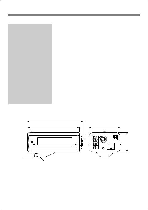
■ Dimensions
Units: mm (inch)
11.2 (0.4)
129.3 (5.1) |
|
119.5 (4.7) |
71 (2.8) |
45 (1.8)
1/4"-20UNC
18

License for Software Contained in CD-ROM
•Please read carefully the terms and conditions contained in the license agreement that appears on the screen during the software installation process. Provided that you have agreed to all the terms and conditions therein, you may use the software subject to the license agreement.
•For information on the other products or services provided by third parties which are introduced in the CD-ROM, please contact each supplier or manufacturer.
Software, this manual and the electronic manual are copyrighted by SANYO Electric Co., Ltd. No materials contained in these manuals may be reproduced in any format without the prior permission of the copyright holder.
•Except for personal use, copyright law prohibits the use of recorded copyrighted images without ht epermission of the copyright holder.
Microsoft, Windows, ActiveX and Internet Explorer are registered trademarks or trademarks of Microsoft Corporation in the United States and other countries.
The official name for “Windows” used in this manual is Microsoft® Windows® Operating System.
In this manual, note that the word “Windows” is used for referring to “Microsoft® Windows® XP Operating System”, and “Microsoft® Windows® Vista operating System”.
Intel and Pentium are registered trademarks or trademarks of Intel Corporation and its subsidiaries in the United States and other countries.
IBM and IBM PC/AT are trademarks of International Business Machines Corporation. Adobe Reader is a trademark of Adobe Systems Incorporated.
UPnP is a trademark of UPnP Implementers Corporation, which is established by the UPnP Forum SC. Java is a trademark of Sun Microsystems, Inc.
MANUEL D’INSTRUCTIONS |
VCC-N6584 |
|
VCC-N6695P |
Caméra CCD couleurs
CETTE INSTALLATION DOIT ETRE EFFECTUEE PAR UNE
PERSONNE QUALIFIEE DU SERVICE TECHNIQUE ET DOIT ETRE
CONFORME A TOUS LES CODES LOCAUX.
Deutsch Español Français English
Veuillez lire ce manuel d’instructions très attentivement afin d’effectuer une installation correcte. Veuillez également lire très attentivement le manuel électronique contenu dans le CD-ROM afin de faire fonctionner la caméra correctement.
Le présent manuel couvre 2 modèles. Les éventuelles différences entre les 2 modèles sont indiquées quand cela est nécessaire.

Table des matières |
|
Informations pour l’utilisateur ...................................................................................... |
2 |
Préparatifs ................................................................................................................... |
4 |
Dénomination et fonctions des pièces......................................................................... |
5 |
Visionnement des images en direct sur un moniteur (Connexions de base) .............. |
6 |
Réglages de la caméra ............................................................................................... |
7 |
Visionnement des images en direct sur un ordinateur (Connexion sur le réseau) ...... |
9 |
Réglages du réseau .................................................................................................. |
12 |
Réglage de la caméra à partir de l’ordinateur ........................................................... |
14 |
Utilisation du CD-ROM fourni .................................................................................... |
16 |
Spécifications ............................................................................................................ |
17 |
■ Vérification de l’environnement d’exploitation
• PC |
: IBM PC/AT ou compatible |
|
• Système d’exploitation |
: Windows Vista/Windows XP Édition Professionnelle SP2 |
|
• Unité centrale |
: Pentium IV (2,0 GHz ou supérieur) |
|
|
|
3,0 GHz ou supérieur pour utiliser le VA-SW3050LITE |
• Mémoire |
: |
1 Go ou supérieur (2 Go ou supérieur pour utiliser Vista) |
• Interface réseau |
: 100Base-TX (connecteur RJ-45) |
|
• Puce graphique |
: Série GeForce 6000 ou supérieure |
|
• Carte d’affichage |
: |
1024 x 768 pixels ou plus, 16 millions de couleurs ou plus |
• Navigateur Web |
: |
Internet Explorer Vers. 6.0 ou supérieure |
1

Informations pour l’utilisateur
Sécurité |
ATTENTION |
RISQUE DE CHOC |
ÉLECTRIQUE |
NE PAS OUVRIR |
ATTENTION: POUR RÉDUIRE LE RISQUE DE CHOC ÉLECTRIQUE, N’ENLEVEZ PAS LE CAPOT (NI LA FACE ARRIÈRE).
IL N’Y A PAS D’ÉLÉMENTS RÉPARABLES PAR L’UTILISATEUR À L’INTÉRIEUR. ADRESSEZ-VOUS POUR LES DÉPANNAGES À DU PERSONNEL QUALIFIÉ.
L’éclair de lumière avec le symbole de flèche dans un triangle équilatéral est destiné à avertir l’utilisateur de la présence de “courant électrique
dangereux” sans isolation à l’intérieur du produit, et qui peut être d’une puissance suffisante pour constituer un risque de choc électrique pour des personnes humaines.
Le point d’exclamation dans un triangle équilatéral est destiné à avertir l’utilisateur de l’existence d’instructions importantes pour la manipulation et la maintenance (dépannage) dans les documents accompagnant le produit.
AVERTISSEMENT: Pour réduire les risques d’incendie ou de choc électrique, n’exposez pas cet équipement à la pluie ou à l’humidité.
ATTENTION: Des changements ou des modifications qui n’ont pas été expressément approuvées par le fabricant peuvent annuler l’autorisation conférée à l’utilisateur de manipuler cet équipement.
Cet équipement a été testé et a satisfait aux limites définies pour un appareil numérique de classe B, conformément à la partie 15 des normes FCC.
Ces limites sont conçues pour offrir une protection raisonnable contre les interférences nuisibles dans une installation résidentielle. Cet équipement génère, utilise et peut émettre de l’énergie
sous forme de fréquence radio et, s’il n’est pas installé et utilisé conformément aux instructions, peut provoquer des interférences nuisibles aux communications radio.
Il n’est toutefois pas garanti que des interférences ne se produiront pas dans une installation particulière.
Si cet équipement provoque des interférences nuisibles à la réception de la radio ou de la télévision, ce qui peut être déterminé en allumant et en éteignant l’équipement, l’utilisateur est invité à essayer de corriger cette interférence
en appliquant une ou plusieurs des mesures suivantes.
•Réorienter ou repositionner l’antenne de réception.
•Augmenter la distance entre l’équipement et le récepteur.
•Connecter l’équipement à une prise de courant d’un circuit différent de celui auquel le récepteur est connecté.
•Consulter le vendeur ou un technicien radio/TV expérimenté pour obtenir de l’aide.
Pour les clients situés au Canada
Cet appareil numérique de classe B est conforme à la norme canadienne NMB-003.
2
Informations pour l’utilisateur
Pour Utilisateurs de l’UE
Svp note:
Votre produit Sanyo est conçu et fabriqué avec des matèriels et des composants de qualité supérieure qui peuvent être recyclés et réutilisés.
Ce symbole signifie que les équipements électriques et électroniques en fin de vie doivent être éliminés séparément des ordures ménagères.
Nous vous prions donc de confier cet équipement à votre centre local de collecte/recyclage. Dans l’Union Européenne, il existe des systèmes sélectifs de collecte pour les produits électriques et électroniques usagés.
Aidez-nous à conserver l’environnement dans lequel nous vivons !
Les machines ou appareils électriques et électroniques contiennent fréquemment des matières qui, si elles sont traitées ou éliminées de manière inappropriée, peuvent s’avérer potentiellement dangereuses pour la santé humaine et pour l’environnement.
Cependant, ces matières sont nécessaires au bon fonctionnement de votre appareil ou de votre machine. Pour cette raison, il vous est demandé de ne pas vous débarrasser de votre appareil ou machine usagé avec vos ordures ménagères.
Ce symbole et le système de recyclage ne sont appliqués que dans les pays UE et non dans les autres pays du monde.
SANYO FISHER Sales (Europe) GmbH
Stahlgruberring 4, D-81829 München, Germany
SANYO Electric Co., Ltd.
1-1, Sanyo-cho, Daito City, Osaka 574-8534, Japan
Précautions
■ En cas de problème
N’utilisez pas l’appareil si de la fumée ou une odeur étrange s’en dégage, ou s’il semble ne pas fonctionner correctement. Éteignez l’appareil immédiatement et débranchez le cordon d’alimentation, puis adressezvous à votre revendeur ou à un Centre de service Sanyo autorisé.
■ Ne l’ouvrez pas et ne le modifiez pas
N’ouvrez pas le boîtier, car cela peut être dangereux et risque de causer des dommages à l’appareil. Pour les réglages internes et les
réparations, adressez-vous à votre revendeur ou à un Centre de service Sanyo autorisé.
■ Faites attention lors de la manipulation de l’appareil
Pour éviter de l’endommager, ne laissez pas tomber l’appareil ou ne le soumettez pas à des chocs ou à des vibrations.
■ Ne mettez pas d’objets dans l’appareil
Assurez-vous qu’aucun objet métallique ou inflammable n’entre dans l’appareil. S’il est utilisé avec un objet étranger à l’intérieur, cela risque de causer un incendie, des courts-circuits ou des dommages. Faites attention pour protéger l’appareil de la pluie, de l’eau de mer, etc. Si de l’eau ou autre liquide entre dans l’appareil, éteignez l’appareil immédiatement et débranchez le cordon d’alimentation, puis adressezvous à votre revendeur ou à un Centre de service Sanyo autorisé.
■ N’installez pas l’appareil près de champs magnétiques
Les champs magnétiques peuvent causer un mauvais fonctionnement.
■ Gardez-le à l’abri de l’humidité et de la poussière
Pour éviter d’endommager l’appareil, ne l’installez pas là où il y a de la vapeur ou de la fumée grasse, où le degré d’humidité risque de devenir trop élevé ou là où il y a beaucoup de poussière.
■ Gardez-le à l’abri des températures élevées
N’installez pas l’appareil près de fours, ou autres appareils qui émettent de la chaleur, comme des projecteurs, etc., ou là où il peut être sujet aux rayons directs du soleil, car cela peut causer une déformation, décoloration ou autres dommages. Faites attention lors de l’installation près du plafond, dans une cuisine ou dans une chambre des machines, car la température risque de monter à un niveau élevé.
■ Nettoyage
•La poussière peut être retirée du boîtier en l’essuyant à l’aide d’un chiffon doux. Pour retirer les taches, essuyez à l’aide d’un chiffon doux humecté d’une solution de détergent doux et bien essoré, puis séchez à l’aide d’un chiffon doux et sec.
•N’utilisez pas de solvants, dissolvant ou autres produits chimiques sur le boîtier, car cela risque de causer une déformation et un écaillage de la peinture. Avant d’utiliser un chiffon traité chimiquement, assurez-vous de lire toutes les instructions qui l’accompagnent. Assurez-vous qu’aucune pièce en plastique ou caoutchouc ne soit en contact avec le boîtier pendant une longue période, car cela risque de causer des dommages ou un écaillage de la peinture.
3

Préparatifs
■ Installation de l’objectif (pour monture CS)
Bornes d’objectif pour objectif à iris automatique
Bobine de frein (+) |
Bobine de frein (–) |
Bobine d’entraînement (–) |
Bobine d’entraînement (+) |
5 mm/0,2 p.o. ou moins
•Si vous utilisez un objectif à monture C, installez une bague d’adaptation en vente dans le commerce.
•Selon le type d’objectif utilisé, il est possible que la forme de la fiche de la lentille ne corresponde pas. Si la forme ne correspond pas, adressez-vous à votre revendeur ou à un agent de service agréé.
■Installation de la caméra
Le support peut être installé soit au-dessus, soit en-dessous, comme indiqué sur l’illustration.
Lorsque vous installez la caméra, vérifiez si les vis peuvent être fermement serrées ou pas. Les plaques de plâtre ou les plaques similaires n’étant pas assez solides, utilisez un dispositif tel qu’une plaque de renfort pour pouvoir serrer fermement les vis.
•Si la luminosité des objets surveillés est supérieure à la luminosité maximale acceptable pour les objets en raison de leur niveau d’éclairage, il est possible qu’un effet de traînage (apparition de bandes verticales ou horizontales dans les parties très lumineuses de l’objet) se produise. Ajustez l’angle d’éclairage pendant que vous effectuez la surveillance de l’objet.
•Choisissez un support de montage de caméra adéquat (en vente dans le commerce) qui puisse supporter le poids total combiné de la caméra et du support de montage, et installez-le bien fermement à un endroit solide.
4

Dénomination et fonctions des pièces
■ Arrière
POWER |
ALARM OUT |
|
|
VIDEO OUT ALARM IN |
|
||
-- AC24V -- DC12V |
|
||
|
COM |
|
|
LAN |
|
||
LINK |
|
||
GND |
|||
|
|
||
CLASS 2 WIRING |
|
|
|
|
|
|
|
Vis de fixation d’arrière de bride |
|
||
Levier de réglage d’arrière de bride |
|
||
Bornes 24 VAC/12 VDC
Connectez cette borne à l’alimentation électrique.
•Quand vous allumez la caméra, l’indicateur POWER s’allume.
Témoin d’alimentation
Bornes d’objectif
Connecteur VIDEO OUT (type BNC)
Utilisé pour émettre les signaux d’images. Connectez à un équipement vidéo tel qu’un moniteur.
Bornes de contrôle
Lorsque vous branchez le câble, pressez la saillie de la borne et maintenez-la enfoncée, insérez le câble dans la borne, puis relâchez la saillie.
•Borne COM (borne de terre)
•Borne ALARM IN
Connectez à un dispositif tel qu’un interrupteur d’alarme extérieur ou un capteur infrarouge.
•Borne ALARM OUT
Utilisé pour raccorder un vibreur externe ou une lampe.
Quand une alarme est détectée, le dispositif raccordé à la borne signale qu’une alarme est détectée.
Connecteur LAN (RJ-45)
Utilisé pour raccorder la caméra à votre réseau.
Témoin LINK
Lorsque la connexion au réseau est correcte, le témoin s’allume 3 secondes après que l’alimentation électrique a été établie.
Il clignote pendant que le transfert des données est en cours.
■ Côté |
|
|
Interrupteurs de réglage de caméra |
||||||||||||||||
|
|
|
|
|
|
|
|
|
|
|
|
|
|
|
|
|
(P7) |
||
|
|
|
|
|
|
|
|
|
|
|
|
|
|
|
Commandes de réglage manuel de |
||||
|
|
|
|
|
|
|
|
|
|
|
|
|
|
|
|||||
|
|
|
|
|
|
|
|
|
|
|
|
|
|
|
|
|
|
|
l’équilibre du blanc |
|
|
|
|
|
|
|
|
|
|
|
|
|
|
|
|
|
|
|
|
|
|
|
|
|
|
|
|
|
|
|
|
|
|
|
|
|
|
|
R: Réglage des rouges |
|
|
|
|
|
|
|
|
|
|
|
|
|
|
|
|
|
|||
|
|
|
|
|
|
|
|
|
|
|
|
|
|
|
|
|
B: Réglage des bleus |
||
|
|
|
|
|
|
|
|
|
|
|
|
|
|
|
|
||||
|
|
|
|
|
|
|
|
|
|
|
|
|
|
|
|
|
|
|
Commande de réglage de l’iris |
|
|
|
|
|
|
|
|
|
|
|
|
|
|
|
|
|
|
|
(LEVEL) |
|
|
|
|
|
|
|
|
|
|
|
|
|
|
|
|
|
|
|
Ce réglage ne peut être effectué que quand |
|
|
|
|
|
|
|
|
|
|
|
|
|
|
|
|
|
|
|
vous utilisez un objectif à iris automatique de |
|
|
|
|
|
|
|
|
|
|
|
|
|
|
|
|
|
|
|
type CC. |
|
|
|
|
|
|
|
|
|
|
|
|
|
|
|
|
|
|
|
Touche de réinitialisation (RESET) |
|
|
|
|
|
|
|
|
|
|
|
|
|
|
|
|
|
|
|
Si la touche est enfoncée pendant 5 secondes |
|
|
|
|
|
|
|
|
|
|
|
|
|
|
|
|
|
|
|
environ, les différents réglages de RÉGLAGE |
|
|
|
|
|
|
|
|
|
|
|
|
|
|
|
|
|
|
|
RÉSEAU (tels que l’adresse IP) sont initialisés |
|
|
|
|
|
|
|
|
|
|
|
|
|
|
|
|
|
|
|
pour les opérations sur le réseau. |
5

Visionnement des images en direct sur un moniteur (Connexions de base)
Veillez à ce que le système ne soit pas alimenté lors du branchement des appareils.
Branchement du moniteur
L’utilisation de câbles autres que ceux spécifiés peut atténuer les signaux video et/ou sync et réduire la qualité de la transmission.
Plus épais que RG-6U (5 C-2 V) : 500 m / 547 yds. max. 
(Alimentation non PoE)
Connexion de l’alimentation
Pour éviter tout risque d’incendie utilisez un fil répertorié UL nominal VW-1.
11
~
CA 24 V ~
GND |
POWER |
VIDEO OUT |
ALARM OUT |
ALARM IN |
|||
-- DC12V |
-- AC24V |
|
|
Vérifiez si la polarité +/– est correcte. 11
+
CC 12 V –
COM
LAN
LINK
GND
CLASS 2 WIRING
11 Plus épais que 18 AWG |
Plus épais que 24 AWG, 600 m / 656 yds. max. |
Sortie du signal d’alarme
Si un témoin est relié à ce câble, il s’allume lorsqu’un signal d’alarme est reçu ou lorsque le capteur intégré détecte un mouvement.
Équipement |
(ALARM OUT) |
|
périphérique |
||
(COM) |
||
extérieur |
•Pour utiliser le réglage ALARM OUT, vous devez effectuer les réglages de ALARM OUT appropriés pour REGLAGES DE CAMERA dans les réglages du réseau.
Entrée du signal d’alarme
Alarme |
(ALARM IN) |
signal |
(COM) |
d’entrée |
•Pour utiliser le réglage ALARM IN, vous devez effectuer les réglages de ALARM IN appropriés pour REGLAGES DE CAMERA dans les réglages du réseau.
6

Réglages de la caméra
Cette caméra a été réglée de manière à pouvoir être utilisée avec un objectif à iris automatique de type CC en vente dans le commerce. Il est possible que ceci ne convienne pas dans certaines conditions de fonctionnement; vous devez alors utiliser les interrupteurs et les commandes latérales pour effectuer les réglages si nécessaire.
• Si vous ne pouvez pas obtenir un réglage correct, adressez-vous à votre revendeur.


|
|
|
Vous pouvez changer les réglages de cette caméra sur la caméra elle-même, et en utilisant les opérations sur le réseau (sauf pour certains réglages). Lorsque vous changez les réglages, vérifiez les réglages de « RÉGLAGES CORPS PRINCIPAL » sous les opérations sur réseau « REGLAGES DE CAMERA ».
• USE (réglage initial): Vous pouvez utiliser les interrupteurs et les commandes situés sur le côté de la caméra pour effectuer les réglages.
• NO USE: Vous pouvez effectuer les réglages de la caméra via les réglages sur le réseau.
■ Réglage de l’arrière de bride
Normalement, aucun réglage n’est nécessaire. Si vous utilisez un objectif zoom et que la mise au point des images n’est pas correcte, réglez l’arrière de bride en procédant comme suit.
|
Desserrez la vis. |
|
Réglez sur la position téléobjectif, |
||
|
||
|
puis réglez la mise au point à l’aide |
|
|
de la bague de mise au point de |
|
|
l’objectif. |
|
Réglez sur la position grand angle, |
||
|
||
puis réglez la mise au point à l’aide |
||
|
du levier de réglage d’arrière de |
|
|
bride. |
|
|
Serrez la vis de fixation d’arrière de |
|
|
bride. |
|
|
Répétez les étapes et jusqu’à ce que |
|
|
la mise au point ne change plus lorsque |
|
|
vous faites passer l’objectif de la position |
|
|
grand angle à la position téléobjectif. |
7
Réglage de l’iris (IRIS)
Pour régler l’ouverture de l’objectif.
Iris automatique (AI) |
Iris électronique (EI) |
(Pour l’utilisation  en intérieur)
•Lorsque vous réglez l’iris électronique, réglez l’objectif à l’ouverture maximum (valeur F minimum).
•Si vous utilisez un iris électronique (objectif à iris fixe ou manuel) sous éclairage fluorescent, il est possible que les images tremblent.
•Si les images générales deviennent trop foncées ou trop claires lorsque vous utilisez un objectif à iris automatique, réglez à l’aide de
la commande de réglage de l’iris (LEVEL).
Réglage diurne/nocturne (D/N)
Réglage automatique |
Image en couleurs fixe |
||||
(ON) |
(OFF) |
||||
|
|
|
|
|
|
|
|
|
|
|
|
|
|
|
|
|
|
|
|
|
|
|
|
Réglage automatique:
Dans l’obscurité, les images en couleurs deviennent automatiquement des images en noir et blanc (non sensibles aux infrarouges).
Noir et blanc |
En couleurs |
Changement de luminance
Image en couleurs fixe:
Les images sont toujours prises en couleurs
Compensation de contre-jour (BLC)
Ce réglage ne peut être effectué que quand vous utilisez un objectif à iris automatique.
|
Calcul multi-points* |
Calcul en zone |
|
|
|
|
|
||||||||||||
Applique la compensation |
centrale |
|
|
|
|
|
|||||||||||||
de contre-jour à l’image |
Applique la |
|
|
|
|
|
|||||||||||||
|
tout entière (MULTI). |
compensation |
|
OFF |
|||||||||||||||
|
|
|
|
|
|
|
|
|
|
de contre-jour au |
|
|
|
|
|
||||
|
|
|
|
|
|
|
|
|
|
|
|
|
|
|
|||||
|
Haut |
|
Normal |
centre de l’image |
|
|
|
|
|
||||||||||
|
|
(CENT). |
|
|
|
|
|
||||||||||||
|
|
|
|
|
|
|
|
|
|
|
|
|
|
|
|||||
|
|
|
|
|
|
|
|
|
|
|
|
|
|
|
|
|
|
|
|
|
|
|
|
|
|
|
|
|
|
|
|
|
|
|
|
|
|
|
|
|
|
|
|
|
|
|
|
|
|
|
|
|
|
|
|
|
|
|
|
|
|
|
|
|
|
|
|
|
|
|
|
|
|
|
|
|
|
|
|
*Si l’arrière-plan des objets est très sombre, réglez sur le calcul en zone centrale.
*Si vous voulez effectuer rapidement la compensation pour l’image tout entière, sélectionnez « haute ».
Équilibre du blanc (WB)
Automatique
Manuelle (MANU)
(ATW)


 (Rouge)

 (Bleu)
Lorsque vous tournez dans le sens des aiguilles d’une montre, la teinte est accentuée.
Compensation d’ouverture (AP)
Contours normaux
Contours plus nets (HI)
(NORM AP)
Réglage du niveau d’iris de l’objectif (LEVEL)
Réglez si les images générales sont trop foncées ou trop claires lorsque vous utilisez un objectif à iris automatique.
(Plus foncé)  (Plus clair)
8

Visionnement des images en direct sur un ordinateur (Connexion sur le réseau)
■Branchement avec la fonction PoE (Power over Ethernet) alimentation électrique
•N’utilisez pas l’alimentation électrique de la caméra.
•N’alimentez pas le concentrateur ni l’adaptateur de l’alimentation PoE tant que l’installation de la caméra n’est pas terminée.
A Reliez la caméra au réseau local (LAN) via un concentrateur de commutation en utilisant des câbles LAN blindés.
Vous pouvez étendre la distance de transmission en utilisant des concentrateurs de commutation multiples avec prise en charge de la fonction PoE.
Pour les détails sur la distance possible, veuillez vous référer à la performance du concentrateur dans les spécifications, etc.
|
Concentrateur de commutation avec |
PC |
|
prise en charge de la fonction PoE |
|
Moniteur |
11 |
|
|
|
11
ALARM OUT
POWER VIDEO OUT ALARM IN DC12V-- AC24V-- 


COM
LAN
LINK
GND
CLASS 2 WIRING
B Reliez la caméra au réseau LAN via un adaptateur d’alimentation et un concentrateur de commutation en utilisant des câbles LAN blindés.
Adaptateur
11
|
|
|
|
|
PC |
|
11 |
|
|||
|
|
|
|
|
|
|
|
|
|
|
|
|
|
|
|
|
|
|
|
|
|
|
|
11
Concentrateur de commutation
1: câble LAN : CAT5 ou supérieur, de type droit, max. 100 m / 109 yds
9
 Loading...