


VCB-3385P
Printed on recycled paper
1AC6P1P2707--
L73R2/XE, L73R5/XE, UK (0503TR-KP-TTC)
SANYO Electric Co., Ltd.
Printed in Taiwan
INSTRUCTION MANUAL
VCB-3385P
VCB-3380P
VCB-3380P-UK
B/W CCD camera
About this manual
Before installing and using the camera, please read this manual
carefully. Be sure to keep it handy for later reference.
Depending on the conditions of use, installation and environment,
please be sure to make the appropriate settings and adjustments.
If you need help with installation and/or settings, please consult
your dealer.
FEATURES
■
■■
■ Backlight compensation
■
■■
■ 1/3-inch CCD solid-state image device (about
470,000 pixels)
■
■■
■ Horizontal resolution of 570 TV lines, S/N ratio of
50 dB min.
■
■■
■ Minimum required illumination of 0.07 lx (F1.2
lens, 50 IRE)
■
■■
■ High speed electronic shutter: 1/50 – 1/100,000
sec.
■
■■
■ Power supply
VCB-3385P: 24 V AC and 12 – 15 V DC
VCB-3380P/3380P-UK: 220 – 240 V AC
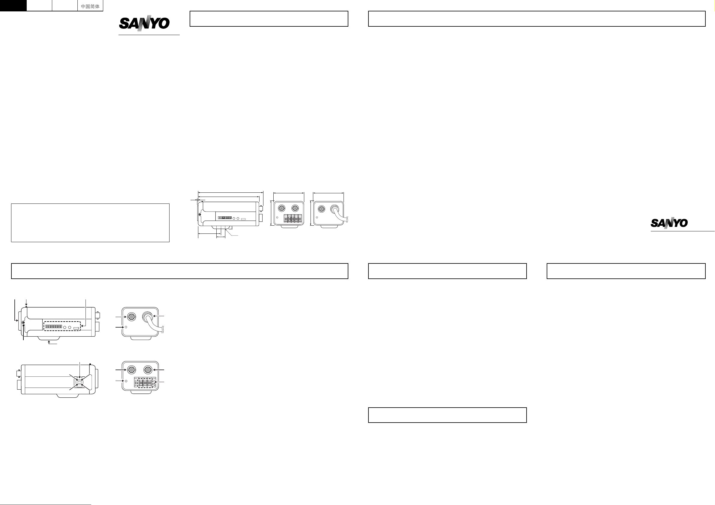
External dimensions
VCB-3385P VCB-3380P
VCB-3380P-UK
0.5
121.3
109.5
14
41.7
9
1/4"-20 UNC
57
45
57
45
PRECAUTIONS
■
■■
■ In case of problem
Do not use the camera if smoke or a strange odor comes from the
unit, or if it seems not to function correctly. Disconnect the power
cord immediately, and consult your dealer or a Sanyo Authorized
Service Center.
■
■■
■ Do not open or modify
Do not open the cabinet, as it may be dangerous and cause damage
to the unit. For internal settings and repairs, consult your dealer or a
Sanyo Authorized Service Center.
■
■■
■ Do not put objects inside the unit
Make sure that no metal objects or flammable substance get inside
the camera. If used with a foreign object inside, it could cause a fire,
short-circuits or damages. If water or a liquid gets inside the camera,
disconnect the power cord immediately, and consult your dealer or
a Sanyo Authorized Service Center. Be careful to protect the
camera from rain, sea water, etc.
■
■■
■ Be careful when handling the unit
To prevent damages, do not drop the camera or subject it to strong
shock or vibration.
■
■■
■ Install away from electric or magnetic fields
If installed close to a TV, radio transmitter, magnet, electric motor,
transformer, audio speakers the magnetic field they generate will
distort the image.
■
■■
■ Protect from humidity and dust
To prevent damages to the camera, do not install it where there is
greasy smoke or steam, where the dampness may get too high, or
where there is a lot of dust.
■
■■
■ Protect from high temperatures
Do not install close to stoves, or other heat generating devices, such
as spotlights, etc., or where it could be subject to direct sunlight, as
that could cause deformation, discoloration or other damages.
Be careful when installing close to the ceiling, in a kitchen or boiler
room, as the temperature may raise to high levels. Install where the
temperature range will stay between –10°C (14°F) and 50°C
(122°F). (no condensation)
■
■■
■ Cleaning
• Dirt can be removed from the cabinet by wiping it with a soft cloth.
To remove stains, wipe with a soft cloth moistened with a soft
detergent solution and wrung dry, then wipe dry with dry soft cloth.
• Do not use benzine, thinner or other chemical product on the
cabinet, as that may cause deformation and paint peeling. Before
using a chemical cloth, make sure to read all accompanying
instructions. Make sure that no plastic or rubber material comes in
contact with the cabinet for a long period of time, as that may
cause damage or paint peeling.
NAMES AND FUNCTIONS OF PARTS
<Figure 1. Right view:>
1 Lens cap
Protects the lens from damage.
2 Flange-back adjustment dial
Adjusts the flange-back distance when a zoom lens is attached.
3 Camera adjustment/setting panel
Contains camera adjustment dials and setting switches.
4 LOCK
Locking screw for the flange-back adjustment dial.
5 Camera attachment bracket
Used to attach the camera.
<Figure 2. Left view:>
6 LENS (lens iris output terminal)
Used to connect the lens plug when the lens is attached.
<Figure 3. Rear view:>
■
■■
■ VCB-3380/3380P-UK
7 VIDEO OUT (video output terminal: BNC connector)
Connects to the VIDEO IN (video input) terminal on the peripheral
equipment.
8 POWER (power indicator)
Lights (red) when the camera power is ON.
9 Power cord
■
■■
■ VCB-3385P
7 VIDEO OUT (video output terminal: BNC connector)
Connects to the VIDEO IN (video input) terminal on the peripheral
equipment.
8 POWER (power indicator)
Lights (red) when the camera power is ON.
F GND, AC24V, DC12V (ground terminal, 24 V AC or
12 V DC input terminal)
G VS IN (External sync composite video signal input
terminal: BNC connector)
<Figure 1. Right view:>
<Figure 2. Left view:>
<Figure 3. Rear view:>
VCB-3380P/3380P-UK
VCB-3385P
1 32
5
4
6
1
33
14
2
7
8
7G
9
F
8
1
Brake coil (–)
2
Brake coil (+)
3
Drive coil (+)
4
Drive coil (–)
TROUBLESHOOTING
Before sending the camera out for repair, check the items below.
If the problem persists after checking these items, contact your
place of purchase or a Sanyo Authorized Service Center.
■
■■
■ If no image appears
• Is the power ON?
• Is the coaxial cable attached securely?
• Are the power and voltage normal?
• Is there adequate illumination?
■
■■
■ If the image is unclear
• Is the lens in focus? Is the flange back distance adjusted
correctly?
• Is the lens dirty?
Dirt or fingerprints on the lens can adversely affect the image.
Gently wipe any dirt or fingerprints off the lens with a soft cloth or
lens cleaning paper and cleaning fluid (commercially available).
• Is the monitor adjusted correctly?
The camera is a precision instrument. Handle it carefully and always follow
the safety precautions. If the camera requires service, never try to repair it
yourself or open the casing.
For servicing, maintenance, or repairs, contact your place of purchase or a
Sanyo Authorized Service Center.
SERVICE
SPECIFICATIONS
Scanning system : CCIR standard
(625 scanning lines, 25 frames/second)
Interlace : PLL 2: 1 interlace
Image device : 1/3-inch solid-state CCD
Number of pixels : 795 (H) × 596 (V)
Number of pixels in image area : 752 (H) × 582 (V)
Sync system : Internal sync/Line lock (manually switched)
VCB-3385P only; External sync (automatically
switched)
Resolution : 570 TV lines
Video output terminal : 1.0 V(p-p)/75
Ω
, composite
Image S/N ratio : 50 dB min.
Electronic shutter speed : 1/50 – 1/100,000 sec.
Minimum required illumination : 0.07 lx approx. (with F1.2 lens, 50 IRE)
Backlight compensation ON/OFF : Set to “ON” or “OFF”
Auto-iris lens output : DC output (variable DC level), 4-pin terminal
Lens mount : CS mount
Flange-back : 12.5 mm (adjustment range: ±0.5 mm)
Auto-iris lens switching : EI/VIDEO/DC
Attachment screw hole diameter : 1/4"-20UNC (top or bottom surface)
Operating environment : Ambient temperature: –10 to +50°C (14 to
122°F)
Humidity: 90% RH max.
Power supply : VCB-3380P/3380P-UK; 220 – 240 V AC/
50 Hz
VCB-3385P; 24 V AC/50 Hz, 12 – 15 V DC
Power consumption : VCB-3380P/3380P-UK; 3.5 W approx.
VCB-3385P; 3.0 W approx.
Weight : VCB-3380P/3380P-UK; 490 g approx.
VCB-3385P; 245 g approx.
Accessories : VCB-3385P only; Clamping core (1 pc.)
Appearance and specifications are subject to change without prior notice.
DeutschEnglish Français
 Loading...