


INSTRUCTION MANUAL BEDIENUNGSANLEITUNG MANUEL D’INSTRUCTIONS
VCB-3100P VCB-3170P
B/W CCD Camera CCD-Schwarzweißkamera Caméra CCD Noir et Blanc
CCD ú
About this manual
•Before installing and using the camera, please read this manual carefully. Be sure to keep it handy for later reference.
•This manual gives basic connections and operating instructions for 2 PAL models (VCB-3170P, 3100P).
Über diese Bedienungsanleitung
•Lesen Sie bitte vor der Montage und dem Inbetriebnehmen der Kamera zuerst diese Bedienungsanleitung sorgfältig durch und bewahren Sie sie zum späteren Nachschlagen auf.
•In dieser Anleitung finden Sie die Anschlüsse und die Grundbedienung für 2 PAL-Modelle (VCB-3170P und 3100P)
À propos de ce manuel
•Avant d’installer et d’utiliser la caméra, veuillez lire ce manuel attentivement. Gardez-le à portée de main pour toute référence ultérieure.
•Ce manuel couvre les branchements et instructions pour l’utilisation de base pour 2 modèles de format PAL (VCB-3170P et 3100P).
•ú
!
•"#2 $PAL % (VCB-3170P, 3100P) &' ()*+ ,-!
Depending on the conditions of use, installation and environment, please be sure to make the appropriate settings and adjustments. If you need help with installation and/or settings, please consult your dealer.
CONTENTS
PRECAUTIONS................................................... |
2 |
PARTS NAMES................................................... |
3 |
MOUNTING THE LENS ...................................... |
5 |
CONNECTIONS .................................................. |
7 |
SETTINGS........................................................... |
8 |
TROUBLESHOOTING....................................... |
12 |
SPECIFICATIONS ............................................. |
13 |
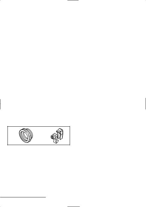
ACCESSORIES
1 C mount adaptor (5 mm) ................ |
1 pc. |
|
|
The C mount adaptor must be used to |
|
|
be able to install a C mount lens on the |
|
|
camera. |
|
2 Lens iris plug (4-pin) ........................ |
1 pc. |
|
1 |
2 |
|
FEATURES
•Built-in interline transfer method 1/3" CCD
–Model VCB-3100P approx. 320,000 picture elements
–Model VCB-3170P approx. 470,000 picture elements
•Low smear, anti-blooming, low lag, no burning and no geometric distortion using the CCD solid state image device.
•100% solid state components giving excellent immunity to shock and vibration
•Not subject to interference from magnetic or electrostatic fields
•High sensitivity, minimum required illumination of 0,1 lux with F1.2 lens
•Horizontal resolution
–Model VCB-3100P more than 400 TV lines
–Model VCB-3170P more than 560 TV lines
•Built-in high speed electronic shutter (with selectable speed setting by internal switches)
•New backlight compensation function (Model VCB-3170P: active when using an auto-iris lens)
•Externally adjustable flange back (mechanical focus)
•Low power consumption and quick start
English 1

PRECAUTIONS
In case of problem
Do not use the camera if smoke or a strange odour comes from the unit, or if it seems not to function correctly. Disconnect the power cord immediately, and consult your dealer (or a Sanyo Authorized Service Centre).
Do not open or modify
Do not open the cabinet, as it may be dangerous and cause damage to the unit. For internal settings and repairs, consult your dealer (or a Sanyo Authorized Service Centre).
Do not put objects inside the unit
Make sure that no metal objects or flammable substance get inside the camera. If used with a foreign object inside, it could cause a fire, short-circuits or damages.
If water or a liquid gets inside the camera, disconnect the power cord immediately, and consult your dealer (or a Sanyo Authorized Service Centre). Be careful to protect the camera from rain, sea water, etc.
Be careful when handling the unit
To prevent damages, do not drop the camera or subject it to strong shock or vibration.
Install away from electric or magnetic fields
If installed close to a TV, radio transmitter, magnet, electric motor, transformer, audio speakers the magnetic field they generate will distort the image.
Protect from humidity and dust
To prevent damages to the camera, do not install it where there is greasy smoke or steam, where the dampness may get too high, or where there is a lot of dust.
Protect from high temperatures
Do not install close to stoves, or other heat generating devices, such as spotlights, etc., or where it could be subject to direct sunlight, as that could cause deformation, discoloration or other damages.
Be careful when installing close to the ceiling, in a kitchen or boiler room, as the temperature may raise to high levels.
Install where the temperature range will stay between –10˚C and 50˚C.
(no condensation)
Cleaning
•Dirt can be removed from the cabinet by wiping it with a soft cloth. To remove stains, wipe with a soft cloth moistened with a soft detergent solution and wrung dry, then wipe dry with dry soft cloth.
•Do not use benzine, thinner or other chemical product on the cabinet, as that may cause deformation and paint peeling. Before using a chemical cloth, make sure to read all accompanying instructions. Make sure that no plastic or rubber material comes in contact with the cabinet for a long period of time, as that may cause damage or paint peeling.
ENGLISH
2 English

PARTS NAMES
1


 5
5
2 
 4
4
3
6 
7
1 2 3 2

 1
1
1 Shorter screws: M3x4
2 Longer screws: M3x6
3Camera mounting screw hole: 1/4"-20 UNC
1 Power indicator (POWER)
Comes on when the power to the camera is on.
2 Video output connector (VIDEO OUT: BNC type)
Connect this connector to a device such as a VCR or monitor with a VIDEO IN connector.
3 AC power cord
4External sync composite video signal input connector (VS IN: BNC type)
Connect to this connector the synchronizing signal output from a synchronizing signal device or the composite signal of a video distributor.
5 Line phase adjustment screw (LINE PHASE)
When using two cameras or more, the image on the monitor may roll vertically when switching sources. This rolling can be minimized by turning this screw.
6 Lens mount cap
The cap is installed to protect the lens mount section.
Remove the lens mount cap before installing a lens (sold separately).
7 Camera installation bracket
The bracket can be fixed at the top or bottom of the camera. When fixing the bracket, be sure to use the longer screws and install the shorter screws on the opposite side to seal the openings.
CAUTION:
When installing the camera support, select a location that can support the total weight of the camera and accessories.
English 3

8
1 3
9
8 Lens iris output connector (4 pin)
This 4-pin connector is used to send the DC control signal and power supply to an auto-iris type lens.
9 Camera setup section (under the cover)
This unit factory settings are as indicated below. These settings are for when using a 1/3 inch CS mount DC (without EE internal amplifier) type lens. However, if due to
24 installation conditions or environment the settings may need to be modified for best results (see page 8 "SETTINGS"). To access the controls, remove the cover fixing screw, then remove the cover.
|
|
[VCB-3170P] |
|
|
|||
|
|
|
|
|
|
h |
|
|
|
|
|
|
|
VR301 L |
|
|
|
|
|
|
|
|
E |
SYNC |
|
E. S. |
|
EI |
|
V |
|
|
|
|
|
E |
|||
AGC |
|
|
|
ON |
L |
H L |
|
L-L |
OFF |
ON |
|
|
|
DC |
|
|
|
|
|
|
OFF |
|
|
INT |
ON |
1 |
2 |
3 |
ON |
|
VIDEO |
|
VR302 |
|
|
BLC |
|
A. I. |
|
|
|
|
|
LENS |
|||
ab |
c |
d g |
|
|
|||
[VCB-3100P]
|
|
|
|
|
|
|
|
|
|
|
|
|
|
|
h |
|
|
||
|
|
|
|
|
|
|
|
|
|
|
|
|
|
|
|
|
|
|
|
|
|
|
|
|
|
|
|
|
|
|
|
|
|
|
VR301 |
|
|
||
|
|
|
|
|
|
|
|
|
|
|
|
|
|
|
L |
|
|||
|
|
|
|
|
|
|
|
|
|
|
|
|
|
|
|
|
|
E |
|
|
|
|
|
|
|
|
|
|
|
|
|
|
|
|
|
|
|
V |
|
SYNC |
AGC |
E. S. |
|
BLC |
EI |
|
|
|
|
|
|
E |
|
||||||
|
|
|
|
|
|
L |
|
H |
L |
|
|||||||||
L-L |
OFF |
|
|
|
|
|
|
|
ON |
|
|
|
|
|
|
|
|
|
|
|
|
ON |
|
|
|
|
|
|
|
DC |
|
|
|||||||
|
|
|
|
|
|
|
|
|
|
|
|
|
|
|
|
|
|||
INT |
ON |
|
|
1 |
2 |
3 |
|
|
OFF |
|
|
|
|
|
VIDEO |
|
|
||
|
|
|
|
|
|
|
|
|
|||||||||||
|
|
|
|
|
|
|
|
|
|
|
|
|
|
|
A. I. |
|
|
||
|
|
|
|
|
|
|
|
|
|
|
|
||||||||
|
|
|
|
|
|
|
|
|
|
|
|
|
|
|
LENS |
|
|
||
|
|
|
|
|
|
|
|
|
|
|
|
|
|
|
|
|
|
|
|
|
|
|
|
|
|
|
|
|
|
|
|
|
|
|
|
|
|
|
|
|
|
|
|
|
|
|
|
|
|
|
|
|
|
|
|
|
|
|
|
ab cef g
|
Control name |
VCB-3170P |
VCB-3100P |
|
|
|
|
|
|
a |
Internal/Line lock switch |
|
INT |
|
|
(SYNC) |
|
|
|
|
|
|
|
|
b |
Auto gain control switch (AGC) |
|
ON |
|
|
|
|
||
c |
High speed electronic shutter |
All OFF: 1/50 sec |
||
|
switches (E.S.) |
|
|
|
|
|
|
|
|
d |
Electronic iris (EI)/ |
OFF |
|
|
|
Backlight compensation (BLC) |
|
|
– |
|
switch |
|
|
|
|
|
|
|
|
e |
Backlight compensation |
– |
|
OFF |
|
switch (BLC) |
|
|
|
|
|
|
|
|
|
|
|
|
|
f |
Electronic iris switch (EI) |
|
– |
|
|
|
|
|
|
g |
Auto-iris lens switch |
|
DC |
|
|
(A.I. LENS) |
|
|
|
|
|
|
||
h |
Lens iris level volume (LEVEL) |
about centre |
||
|
|
|
|
|
Note: |
|
|
|
|
•The EI/BLC switch d is used for an auto-iris lens, therefore the two settings cannot be used simultaneously.
•When using a 1/2 or 2/3 inch C mount VIDEO (with EE internal amplifier) auto-iris type lens, set the A.I. LENS switch to the VIDEO position.
4 English
 Loading...