


VCC-HD5600/HD5600P series
Features of This Camera
Specifications
Target size and recording time
Power Unit Connection and Settings
Introduction1/14
The camera supports network operation. By simply connecting a LAN cable to it, you can construct the most advanced network monitoring system. From the Web browser (Internet Explorer) installed on your PC, you can operate the camera via the network in an easy-to-use manner.
The camera supports bidirectional audio communications, enabling you to communicate with people at the camera from your PC while monitoring the surveillance video, instead of just hearing sounds from the camera.
The camera has 2-megapixel CMOS sensor that produces clear images at ultra-high resolution.
Using multi-stream video transmission, it can simultaneously deliver up to four video/image streams. Because it allows video/image compression format, resolution, and other image conditions to be set as desired for each stream, you can choose the optimal video/image for your application.
Installation of the HDMI option board (sold separately) on the camera enables you to monitor surveillance video in full hi-vision.
You can freely control camera lens orientation with your PC mouse.
With a 10× built-in optical zoom lens, the camera offers a zoom magnification of up to 160× in conjunction with the electronic zoom function.
By installing an SD memory card or external hard disk (sold separately), surveillance video can be recorded on the camera side.
The camera's motion sensor function can work in conjunction with any external alarm device, facilitating the construction of a high-level security system.
Installing associated software applications on your PC further extends the capabilities of your surveillance system.
H.264 Plug-in (supplied): Surveillance video can be viewed in H.264 format.
Auto IP Setup (supplied): This searches your local network for cameras and allows IP addresses to be set at once.
This downloads image data recorded on the camera to your PC.
This plays back image data that has been downloaded to your PC.
This allows you to simultaneously monitor multiple camera video images on a multi-view screen.
This allows you to record and play back video images from the camera on your PC that are distributed over the network.
Introduction 2/14

This device is composed of a camera unit, power unit (VA-94S) and surface cover (supplied).
Image pickup device |
1/2.5” CMOS sensor |
Effective pixels |
16:9 1920 (H) × 1080 (V), 4:3 1600 (H) × 1200 (V) |
|
|
Lowest image |
50IRE: 2.0 lx (F1.8, in color mode with high gain) |
illumination |
50IRE: 0.1 lx (F1.8 in black-and-white mode with high gain) |
|
|
Video S/N ratio |
50 dB or higher (when AGC is 'OFF') |
|
|
Lens |
Focal Length: f=6.3 - 63 mm |
|
F number: F1.8 - 2.5 |
|
Optical zoom 10x, electronic zoom 16x (up to 160x when used in combination with |
|
the optical zoom) |
|
|
Rotational scope |
Pan: 360° endless pan |
|
Tilt: –20 to +200° |
|
|
Rotation speed |
Pan: Max. 420°/sec. |
|
Tilt: Max. 360°/sec. (0.1 to 120°/sec during manual operation) |
|
|
Preset position |
Max. 255 |
|
|
Auto mode |
Sequential, auto pan, tour, automatic return |
|
|
Day/Night function |
Auto, color, black-and-white, alarm input switching |
|
|
White balance |
Auto (ATW), one push (AWC), manual (R/B gain adjustable), indoor, outdoor, |
|
fluorescent |
|
|
Backlight compensation |
Multi-spot evaluative metering, center-weighted evaluative metering, masking, face |
|
detection |
|
|
Electronic sensitivity |
Auto (32× max) or Off |
boosting |
|
|
|
Electronic shutter |
VCC-HD5600P: 1/25, 1/50, 1/120, 1/250, 1/500, 1/1000, 1/2000, 1/4000, 1/10000 |
|
VCC-HD5600: 1/30, 1/60, 1/100, 1/250, 1/500, 1/1000, 1/2000, 1/4000, 1/10000 |
|
Long exposure shutter (1×, 2×, 4×, 8×, 16×, 32×) |
|
|
Iris |
AUTO/MANUAL (electronic iris: ON/OFF) |
|
|
Camera settings |
Up to 8 patterns of monitoring conditions are configurable. |
|
|
AGC gain |
Normal/Middle/High (Manual gain setting possible at Off) |
|
|
Gamma correction |
0.45, 1, Mode 1, Mode 2 |
|
|
Aperture compensation |
On/Off (Correction level adjustable) |
|
|
VIVID COLOR EFFECT |
ON/OFF |
|
|
DNR (digital noise |
ON/OFF |
reduction) |
|
|
|
Image inversion |
Horizontal/Vertical/Horizontal and vertical/Off |
|
|
Privacy mask |
ON/OFF, up to 32 positions |
|
|
Motion sensor |
ON (detection area setting, video analytics)/OFF, face detection function |
|
|
Auto pursuit |
ON/OFF |
|
|
Sway compensation |
ON/OFF |
|
|
Language selection |
English, French, German, Spanish, Japanese |
|
|
Introduction 3/14

I/O
Video output |
Monitor output terminal (BNC) |
|
LAN |
10BASE-T/100BASE-TX (RJ-45 connector) |
|
|
|
|
EX-HDD Connector |
For external hard disk (VA-HDC4000) connection |
|
|
|
|
SD Card Slot |
1 |
(SDHC compliant, max. 32 GB supported) |
|
|
|
Alarm input |
8 |
(NO/NC), also serving as Day/Night switching terminal <control terminal> |
|
|
|
Alarm output |
2 |
(NO/NC switching, 16 V, 150 mA, open collector) <control terminal> |
|
|
|
Audio input/output |
Audio input (white: 3.5-mm mini jack) |
|
|
Audio output (black: 3.5-mm mini jack) |
|
|
|
|
Communication method |
RS-485 |
|
|
|
|
Protocol |
SSP, PELCO-D |
|
|
|
|
Baud Rate |
2400, 4800, 9600, 19200 |
|
|
|
|
Address |
1 |
- 255 (sanyo SSP: 1 to 127) |
|
||
HDMI output: Possible when an HDMI option board (VA-HDB90, sold separately) is attached |
||
Recording media
SD memory card |
Normal recording, alarm recording, backup video recording in event of a network |
|
failure, log information |
|
|
External HDD |
Normal recording, alarm recording, backup video recording in event of a network |
|
failure, log information |
|
|
Network
Image/video |
H.264/JPEG |
compression |
|
|
|
Video size (H.264) |
(16:9) 1920×1080, 1280×720, 640×360, 320×180 |
|
(4:3) 1600×1200, 1280×960, 1024×768, 640×480, 320×240 |
|
|
Video size (JPEG) |
(16:9)1920×1080, 1280×720, 1024×576, 640×360 |
|
(4:3) 1600×1200, 1280×960, 1024×768, 800×600, 640×480, 320×240 |
|
|
Picture quality |
QUALITY mode: BASIC, NORMAL, ENHANCED, FINE, SUPER FINE |
|
BITRATE mode: User-specified bit rate |
|
|
Interface |
10BASE-T/100BASE-TX |
|
|
Protocol |
TCP/IP, UDP, HTTP, HTTPS, SMTP, NTP, DHCP, FTP, DDNS, RTP, RTSP, RTCP |
|
|
Audio |
G.711 (Bidirectional) |
|
|
Simultaneous access |
20 |
|
|
Security |
BASIC authentication (ID/password), SSL, IP filtering |
|
|
Power source
Operating ambient |
–10 to +50°C/14 to 122°F |
temperature/humidity |
90% RH or less (no condensation) |
|
|
Power source |
24 VAC±10%, 50/60 Hz |
|
|
Power consumption |
29 W |
|
|
Introduction 4/14
Weight |
Approx. 1.9 kg/67.0 oz. |
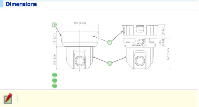
Dimensions |
Unit: mm (inch) |
ACamera unit: approx. 1.3 kg/45.9 oz.
BPower unit: Approx. 450 g/15.9 oz.
CSurface cover: approx. 110 g/3.9 oz.
Appearance and specifications are subject to change without prior notice or obligations.
Introduction 5/14

This table is displayed using a browser-specific function and therefore not displayed on the PDF manual.
Refer to the table “Target size and recording time” in the electronic manual.
This table is displayed using a browser-specific function and therefore not displayed on the PDF manual.
Refer to the table “Target size and recording time” in the electronic manual.
Introduction 6/14

This device is composed of a camera unit, power unit (VA-94S) and surface cover (supplied). When using this camera, connect and configure the power unit.
 For details on terminal connections, recording media attachment and switch settings, etc., please refer to “Connection” and “Control/Address Setting”.
This is the connection point between the camera unit and the power unit.
AControl switch (transmission rate and protocol setting, etc.)
BAddress switch (camera control address setting)
CControl terminal (connection of controller and alarm input/output cable)
Top ( A ): LAN terminal (RJ-45 type)
Use this socket to connect the camera to your PC to enable network operation.
Introduction 7/14

Bottom ( B ): EX-HDD terminal (USB type)
When recording live video onto an external hard disk, put the hard disk in a dedicated hard disk case (VAHDC4000, sold separately) and then connect the case to the camera.
When recording live video onto an SD memory card, insert the card into the slot.
Connect this terminal to the power supply.
There is no power indicator on the camera.
Connect this jack via an audio cable to the audio input jack of an amplified speaker system or the monitor.
Use this jack to connect an external microphone to listen to the sound while monitoring the live video, or simultaneously record the video and sound.
Connect this terminal to a monitor, etc. A live video will be displayed on the monitor once the camera is turned on.
By installing an HDMI option board (VA-HDB90, sold separately), the camera can be connected to a high vision monitor.
Perform the following connections according to the installation environment and application of your camera.
APower Connection
BNetwork Connection
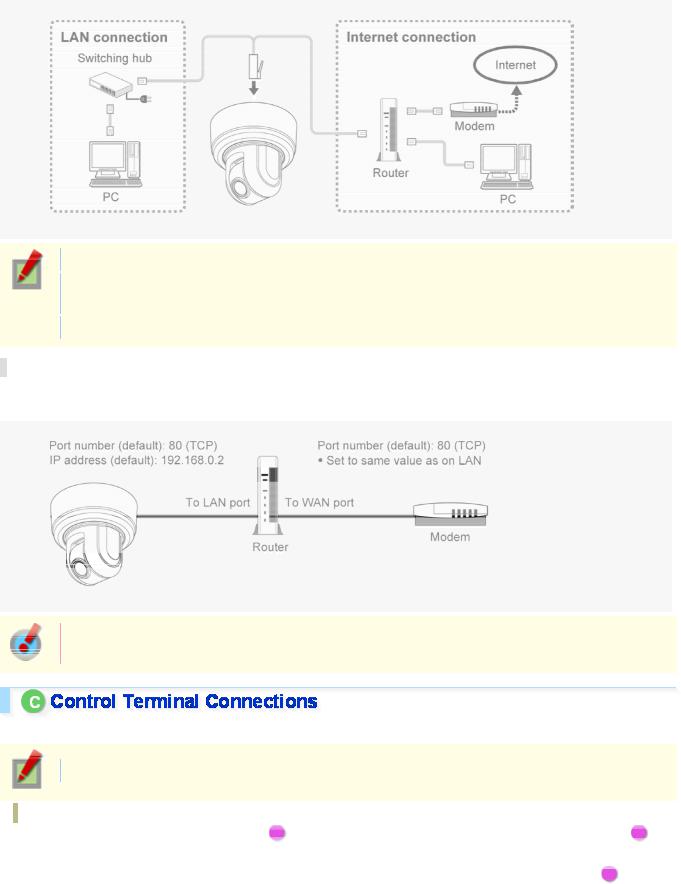
CControl Terminal Connections
DAudio Jack Connection
EInstalling Recording Media
Before attempting the following connections, be sure to turn off all components of your system.
Improper connection may cause smoke or failures. Before attempting to connect each system component, carefully read the instruction manual that comes with it to familiarize yourself with the correct connection procedure.
Introduction 8/14

There are two types of power unit, i.e. 24 VAC and 230 VAC. Before using, always make sure of the purchased model number and arrange the wiring correctly.
24 VAC Type
Connect the power cable to the power terminal. Although the power terminals have no polarity, the earth grounding wire must be connected to the GND (earth grounding) terminal.
To prevent a fire hazard use any UL listed wire rated VW-1.
Be sure to use an 18AWG or thicker wire power cable.
230 VAC Type
Please refer to the instruction manual that came with the product.
This camera is designed so that you can use all of its functions via network operation.
By connecting the network (LAN) socket of the camera to your PC using a LAN cable, you can configure and operate it from the Web browser installed on your PC.
Introduction 9/14
Use a LAN cable no longer than 100 m (109.4 yards) with the shield type CAT5 or higher.
Use a straight-type cable if connecting to LAN, and use a cross-type cable if directly connecting the camera to a PC.
The supported Web browser is Internet Explorer Ver.6.0 SP2 or higher, or Internet Explorer Ver.7.0.
About the internet connection
Port forwarding for the video port must be enabled on the broadband router.
For details on how to set port forwarding, please refer to your router's Instruction manual.
To connect two or more cameras, on the NETWORK SETTINGS screen, assign them with port numbers that are different from that of the first camera.
Connect the alarm input/output cable and controller to the control terminal of the interface board.
Use a thicker cable than 24AWG for connection. (Maximum length 600 m)
Installing and removing the interface board
To place the board back, align the hole ( A ) at the right corner of the board to the protruding portion ( B ) and securely fix the board by depressing it.
To connect alarm or other cables to the interface board, take out the board by pulling the portion C .
Introduction 10/14
1 Outputting Alarm Signals (OUT 1-2)
Connect a buzzer, lamp, or other alarm device to the alarm output cable.
Alarm can be output via two channels.
After connecting an alarm device, configure the output conditions for the corresponding alarm output terminal (ALARM OUT1 or 2) via network operation on the ALARM SETTINGS screen.
Configuration of alarm output terminal is also possible via remote operation. For that, set [ALARM OUT] to “REMOTE” on the ALARM SETTINGS screen.
2 Inputting Alarm Signals (IN 1-8)
Connect an alarm switch, infrared sensor, or other device to detect alarm conditions to the alarm input cable. Alarm can be input via eight channels.
After connecting an alarm device, configure the input conditions for the corresponding alarm input terminal (ALARM IN1 or 2) via network operation on the ALARM SETTINGS screen.
When using the alarm input terminal for day/night switching, configure the following settings.
Under [DAY/NIGHT], set [DAY/NIGHT] to “COLOR” and select the terminal you want to use in [EXT ALARM].
On the ALARM SETTINGS screen, in [POLARITY], select the signal polarity of the alarm input terminal.
Connecting an external switch to ALARM IN1 allows you to set the system clock by operating the switch. To set the system clock, configure the [CLOCK IN] setting on the CLOCK SETTINGS screen.
3 Connecting the Controller (485A/485B)
By connecting a system controller (sold separately), the camera can be controlled remotely.
Configure the protocol, baud rate and address. (Refer to “Control/Address Settings”).
AUDIO OUT Jack (Black)
Connect this jack via an audio cable to the audio input jack of an amplified speaker system or the monitor.
AUDIO IN Jack (White)
Use this jack to connect an external microphone to listen to the sound while monitoring the live video, or simultaneously record the video and sound.
Introduction 11/14

This jack supports 3.5-mm diameter monaural microphone plugs, or monaural line-level input plugs (the left channel only for stereo plugs).
When recording live video on the camera, install an SD memory card or external hard disk on the camera.
Always turn the power off when installing a recording medium.
1 Connecting an External Hard Disk
Put the hard disk in a dedicated hard disk case (VA-HDC4000, sold separately) and then connect the case to the camera.
2 Inserting an SD Memory Card
Insert the SD card into the slot until it is locked with a clicking sound.
Push the SD card a bit further into the slot to eject it.
When you insert a new recording medium, format it on the SD/HDD screen.
When you remove the recording medium, first set [SD MEMORY CARD]/[HDD] on the SD/HDD screen to “NO USE”.
When you connect the camera to a controller, it is necessary to configure the interface board control switch and address switch.
This is used to configure transmission rate and protocol, etc.
Switches 4 and 5 are not used.
Settings in bold typeface in the table below show the factory default configurations.
Introduction 12/14

1 Baud Rate
Configure the transmission rate of connected devices to the transmission rate of the camera.
Transmission Rate Switch 1 Switch 2
2400 |
OFF |
OFF |
|
|
|
4800 |
ON |
OFF |
|
|
|
9600 |
OFF |
ON |
|
|
|
19200 |
ON |
ON |
|
|
|
When protocol is set to “PELCO”, set to 2400.
2 Protocol
Select the protocol for controlling the camera.
Protocol |
Switch 3 |
Corresponding Protocol |
|
|
|
SSP (SANYO) |
OFF |
Automatic switching between Sanyo SSP and high speed SSP |
|
|
|
PELCO |
ON |
Automatic switching between PELCO-D and PELCO-P |
|
|
|
3 Terminator
When you connect multiple cameras, set the terminator setting (Switch 6) of the final device to “ON” and all other devices to “OFF”.
When you connect multiple cameras, allocate a unique RS485 protocol address (camera number) to each camera.
Configure the address by setting the dip switches to “ON” and “OFF”.
Configure the switches according to the List of Address Configuration Switches shown below. Circles in the list indicate “ON”.
When protocol is “SSP (SANYO)”:
Configurable addresses: 1 to 127
Switch 8 is configured to “OFF”.
When protocol is “PELCO”:
Configurable addresses: 1 to 255
To configure the address to a number between 128 and 255, set the switch 8 to “ON”.
Introduction 13/14

List of Address Configuration Switches
Introduction 14/14

VCC-HD4600/HD4600P
From Connection to Network Operation Live Video Monitoring
Alarm Detection and Output
Recording Surveillance Video
Software Information Configuration menu quick reference tables
Quick Operation Guide1/14
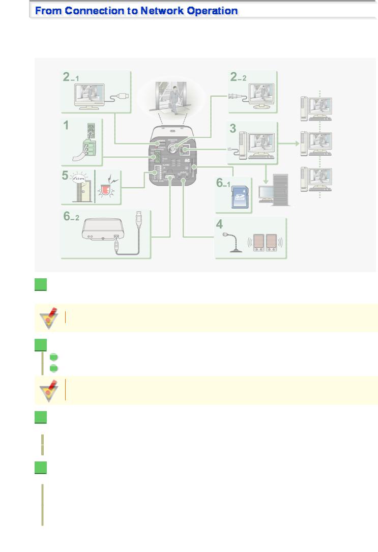
Follow the steps below to set up and connect the camera to your PC.
You can use video recording, bidirectional audio communications, and other standard functions of the camera, in addition to normal live video monitoring.
1  Connect the power cable to the power terminals.
Use a 24-VAC or 12-VDC power supply.
Do not turn on the camera until you complete all connections.
2  Connect the monitor to the appropriate terminal.
1High-definition monitor: HDMI terminal
2Monitor for video adjustment: MONITOR OUT terminal
The video cannot be output to the HDMI and MONITOR OUT terminals simultaneously. Set the preferred output terminal under TV OUT on the VIDEO & AUDIO SETTINGS screen.
3  Connect the network (LAN) socket to your PC using a LAN cable.
Check the operating environment of your PC and perform the following operations:
Check the network information on your PC.
Install the “H.264 Plug-in” from the supplied CD-ROM onto your PC.
4  Connect a microphone and a speaker system to the audio input and output jacks of the camera.
AUDIO IN jack: Use this jack to connect an external microphone to hear the sound with live video, or simultaneously record the video and sound.
AUDIO OUT jack: Use this jack to connect an amplified speaker system to send audio messages from your PC to the camera.
Quick Operation Guide 2/14

5  Connect necessary external devices to the alarm input/output terminals.
ALARM IN1/2 terminal: Connect an external switch, infrared sensor, or other device to detect alarm conditions such as entry of an intruder.
ALARM OUT 1/2: Connect a buzzer, lamp, or other alarm device to output a signal to warn people of the occurrence of an alarm condition.
6  Install the recording medium.
After installation, the medium requires to be formatted.
1SD memory card: Insert it into the SD card slot.
2External hard disk: Connect the drive to the EX-HDD terminal.
7  Turn on the camera.
The power indicator lights up and live video appears on the monitor.
8  Access the camera from your PC's Web browser.
Live video appears on the live screen. Now, you can perform all network operations from your PC.
Quick Operation Guide 3/14

If you are operating the camera for the first time, check the factory default video and audio conditions on the VIDEO & AUDIO SETTINGS screen. Change the default settings as desired.
For details, refer to the “VIDEO & AUDIO SETTINGS” section.
16:9 (Default) → 4:3
By default, the list shows the two stream patterns, STREAM1 and STREAM2. Use the buttons provided below the list to add, change, or delete stream patterns.
The factory default settings for STREAM1 and STREAM2 are as shown in the screenshots below.
 ADD
ADD  : Use this button to add up to two custom stream patterns (STREAM3 and STREAM4).
 CHANGE
  : Use this button to change stream settings (STREAM1 to STREAM4).
 DELETE
  : Use this button to delete registered stream patterns.
Digital PTZ Function
The digital PTZ function lets you clip specific areas of the subject in VGA size and perform zoom, pan, and tilt operations just as when using a PTZ camera.
To use the digital PTZ function, set [DIGITAL PTZ] to “ON” on the JPEG stream registration screen shown above (STREAM2 screen in this example) and click 
 on the live screen.
Quick Operation Guide 4/14

You cannot select “ON” in [DIGITAL PTZ] if you selected “H.264” in [CODEC].
Selecting “ON” in [DIGITAL PTZ] fixes the [RESOLUTION] value to a VGA-equivalent size (“640× 360” in 16:9 aspect ratio or “640×480” in 4:3 aspect ratio).
Audio condition configuration
In [MIC SENSITIVITY], select the microphone sensitivity.
In [FILTER (500Hz)], enable or disable the audio filter.
In [OUTPUT LEVEL], select the desired audio output level.
Audio output configuration
Set [AUDIO (CAMERA TO PC)] to “ON” on the CLIENT SETTINGS screen.
Audio input configuration
Set [AUDIO (PC TO CAMERA)] to “ON” on the CLIENT SETTINGS screen.
Quick Operation Guide 5/14
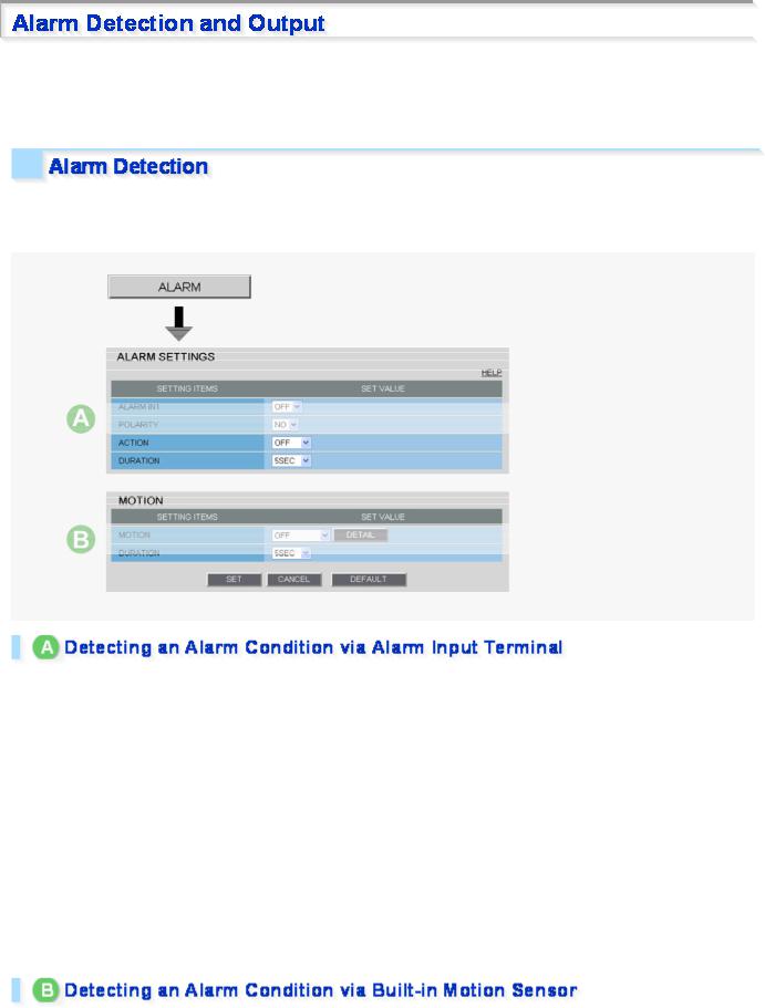
If you are operating the camera for the first time, check the factory default alarm detection conditions on the ALARM SETTINGS screen. Change the default settings as desired.
For details, refer to the “ALARM SETTINGS” section.
You can configure the camera to detect alarm conditions via the “alarm input terminals” or “built-in motion sensor”. For how to configure the camera to detect alarm conditions via the alarm input terminals, refer to the “Alarm Input/Output Terminal Connections” section.
Connecting an alarm switch, infrared sensor, or other external device to the ALARM IN1/2 terminal enables the camera to detect alarm conditions such as entry of an intruder.
Setting Item |
Default Setting |
Optional Setting |
|
|
|
|
|
ALARM IN1/2 (Alarm input terminal |
OFF (Disables alarm |
ON (Enables alarm detection.) |
|
number) |
detection.) |
|
|
|
|
|
|
POLARITY (Signal polarity) |
NO (Ex.: Detects an alarm |
NC (Ex.: Detects an alarm when door is |
|
when door is closed) |
opened.) |
||
|
|||
|
|
|
|
ACTION (action the camera makes when |
OFF (No action) |
ZOOM (Zooms to the specified magnification.) |
|
|
CAM1/CAM2 (Switches the monitoring |
||
an alarm condition is detected) |
|
||
|
condition.) |
||
|
|
||
|
|
|
|
DURATION (Alarm retention duration) |
5SEC (Ex.: Records alarm |
10SEC to 5MIN, CC (Retains the alarm state as |
|
video for 5 sec.) |
long as the alarm signal persists.) |
||
|
|||
|
|
|
The camera uses the built-in motion sensor to detect alarm conditions.
The motion sensor detects an alarm condition in three ways as follows.
Quick Operation Guide 6/14
Setting Item |
Default Setting |
|
Optional Setting |
|
|
|
|
|
|
MOTION (Use of built-in |
OFF (Disables alarm |
A |
MASKING |
|
detection.) |
B |
DETECT |
||
motion sensor) |
||||
|
C ANALYTICS |
|||
|
|
|||
|
|
|
||
DURATION (Alarm retention |
5SEC (Ex.: Records alarm |
10SEC to 5MIN, CC (Retains an alarm state as long as |
||
duration) |
video for 5 sec.) |
the motion alarm persists.) |
||
|
|
|
|
|
ADisabling motion detection in masked areas
BDetecting motion in specific areas
CDetecting motion with lines and areas drawn on the screen
In [MOTION], after selecting a motion sensor type, click  DETAIL
  to configure the detection conditions on the detailed configuration screen.
You can configure the camera to “automatically output alarm signals” or “remotely (manually) output alarm signals”.
You can configure the camera to automatically output an alarm signal when either of its alarm input terminals receives an alarm signal.
Quick Operation Guide 7/14
Setting Item |
Default Setting |
|
|
|
|
ALARM OUT1/ 2 (Alarm |
OFF (Disables alarm output.) |
|
output terminal number) |
|
|
|
|
|
POLARITY (Signal polarity) |
NO |
|
|
|
|
ALARM OUT TIME (Alarm |
5SEC (Ex.: Beeps a warning for 5 sec.) |
|
output time) |
|
|
|
|
|
ALARM IN (Output |
ALARM IN1 (Triggers alarm output when |
|
ALARM IN1 terminal receives an alarm |
||
condition) |
||
signal.) |
||
|
||
|
|
|
MOTION (Output condition) |
OFF (Disables alarm output using motion |
|
sensor.) |
||
|
||
|
|
Optional Setting
ON (Enables automatic alarm output.)
NC
2SEC to 5MIN
ALARM IN2 (Triggers alarm output when ALARM IN2 terminal receives an alarm signal.)
ON (Triggers alarm output using motion sensor.)
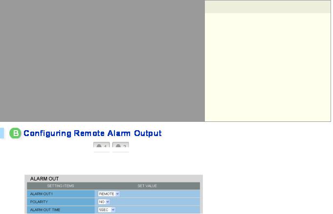
Use the Remote Alarm buttons (
 ) provided on the live screen to send alarm signals from the camera's alarm output terminals.
|
|
|
|
|
|
|
|
Setting Item |
Default Setting |
Optional Setting |
|
|
|
|
|
ALARM OUT1/ 2 (Alarm output |
OFF (Disables alarm |
REMOTE (Enables remote alarm output.) |
|
terminal number) |
output.) |
|
|
|
|
|
|
POLARITY (Signal polarity) |
NO |
NC |
|
|
|
|
|
ALARM OUT TIME (Alarm output |
5SEC (Ex.: Beeps a warning |
2SEC to 5MIN, CC (Stops alarm output when Remote |
|
time) |
for 5 sec.) |
Alarm button is clicked.) |
|
|
|
|
|
Quick Operation Guide 8/14
Before recording video, install a recording medium (SD memory card or external hard disk) on the camera and perform the following procedures.
You can record the following videos or information on the media. Normal recording
Alarm video recording
Backup video recording in event of a network failure
Manual video recording triggered by the emergency recording button
Access and system logs
In cases where both an SD memory card and an external hard disk drive are simultaneously connected, the hard disk drive takes precedence.
The recorded video cannot be played back on the camera. To play back the recorded video, use the supplied downloader software (HDC Downloader) and playback software (DLViewer) to play back the video on the PC.
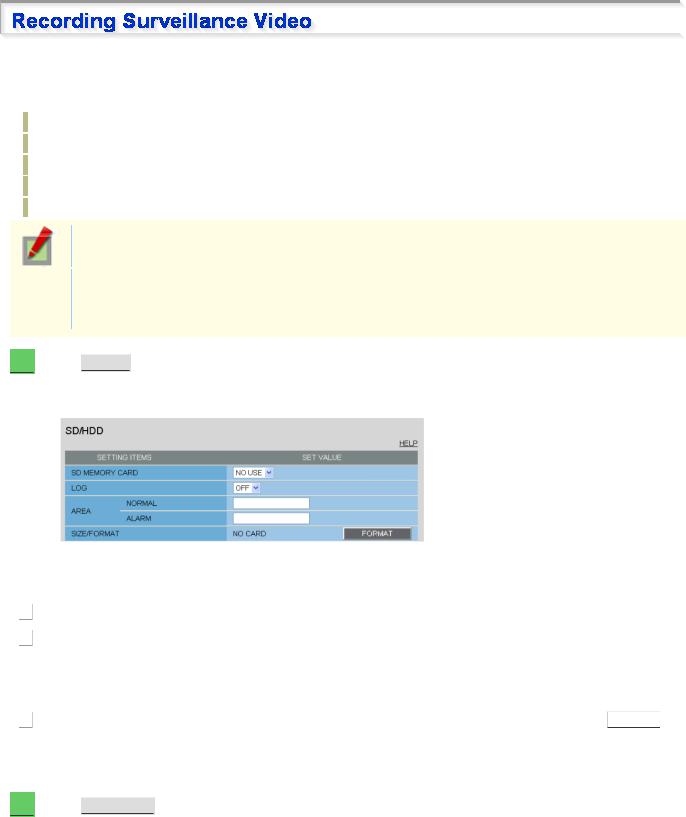
1  Click
Click  SD/HDD
  in the configuration menu.
On the SD/HDD screen, you can format the recording media.
|
|
|
|
|
|
|
|
|
|
|
|
|
|
|
|
|
|
Setting Item |
Default Setting |
Required Setting/Operation |
|
||
|
|
|
|
|
|
|
|
|
1 |
SD MEMORY CARD/HDD |
NO USE |
USE (Use the media for recording) |
|
||
|
|
|
|
|
|
|
|
|
AREA (Ratio of the |
NORMAL: 80 (Normal recording |
Change the rate between the “NORMAL” and |
|
|||
|
2 |
|
|||||
|
recording areas) |
storage area) |
“ALARM” areas as needed. |
|
|||
|
|
|
ALARM: 20 (Alarm/backup |
|
|
|
|
|
|
|
recording storage area) |
|
|
|
|
|
|
|
|
|
|
|
|
|
3 |
SIZE/FORMAT |
Displays the recording capacity of |
Check the storage capacity and click |
FORMAT |
. |
|
|
|
|
the media. |
|
|
|
|
|
|
|
|
|
|
|
|
When finished formatting the SD memory card, close the SD MEMORY CARD screen.
2  Click
Click  RECORDING
  in the configuration menu.
On the RECORDING screen, configure the recording settings as follows.
Quick Operation Guide 9/14

|
|
Setting Item |
Default Setting |
|
|
|
|
|
RECORD STREAM |
OFF |
|
|
1 |
||
|
|
|
|
|
AUDIO |
OFF |
|
|
2 |
||
|
|
|
|
|
ALTERATION |
OFF |
|
|
3 |
||
|
DETECTION |
|
|
|
|
|
|
|
ALARM EVENT1 |
OFF |
|
|
4 |
||
|
|
|
|
|
TRIGGER (Recording |
ALARM IN1 (Triggers recording when |
|
|
5 |
||
|
trigger conditions) |
ALARM IN1 terminal receives an alarm |
|
|
|
|
signal.) |
|
|
|
|
|
PRE ALARM |
OFF |
|
|
6 |
||
|
|
|
|
|
REC BUTTON |
OFF |
|
|
7 |
||
|
|
|
|
Required Setting
Select the desired stream (STREAM1 to STREAM4).
ON (Records video and sound simultaneously)
ON (Detects tampered images)
ON
You can configure three patterns of recording conditions (for ALARM EVENT1 to 3).
ALARM IN2, MOTION, ALARM OUT1/2, NETWORK FAILURE
ON (Records video for a specific period before alarm occurrence.)
ON (Records video using the emergency recording button on the live screen control panel)
When finished configuring the above basic recording settings, configure the recording schedule as required.
3  On the RECORDING screen, click
  SCHEDULE
  .
.
|
|
|
|
|
|
|
|
|
|
|
|
|
|
Setting Item |
Default Setting |
Required Setting |
|
|
|
|
|
|
|
|
1 |
SCHEDULE |
OFF |
ON (Enables recording schedule configuration.) |
|
|
|
|
|
|
|
|
SUN to SAT (START/END) |
00:00/00:00 |
Configure the start/end time of recording for each day of the week. |
|
|
|
2 |
|
|||
|
|
|
|
(Ex.: 08:00/20:00) |
|
|
|
|
|
|
|
|
DAILY |
00:00/00:00 |
Select this check box to set the same start/end time for every day. |
|
|
|
3 |
|
|||
|
|
|
|
|
|
Quick Operation Guide 10/14

When finished configuring the schedule settings, the schedule map appears.
Recording video to your PC
By using the recorder/player application VA-SW3050 Server/Client (optional), you can record and play back streaming video data from the camera on your PC.
To make the maximum use of this camera, we recommend that you use this application.
You can record JPEG images only.
You need to configure recording and other conditions on the application's configuration screens.
Recording video to an FTP server
To record video by sending image data from the camera to an FTP server, you need to configure the image transmission conditions on the FTP SETTINGS screen.
You can record JPEG images only.
Quick Operation Guide 11/14

You can install the following software on your PC to extend the capabilities of your surveillance system.
The CD-ROM that comes with the camera includes all the supplied software.
A H.264 Plug-in (Plug-in for monitoring live video as high-quality moving images)
This plug-in software is required to display H.264 video on the live screen. Be sure to install it on each computer from which you access the camera via network operation.
B HDC Downloader (Application for downloading the video recorded on the camera's recording media (SD memory card/external hard disk) to the PC)
You can download JPEG image and H.264 video data.
The application lets you search for the video/image data to download by date and time or by alarm event. It is also possible to connect a recording medium to your PC to directly copy video/image data.
C DLViewer (Application for playing back downloaded alarm video, etc.)
You can play back JPEG image and H.264 video data.
The application also offers the capability to save and print video/image data.
D VA-SW3050Lite (Application for monitoring live video from more than one camera)
This monitoring application is designed for use with SANYO network cameras.
You can access up to 128 cameras simultaneously.
The application lets you monitor video images from connected cameras in either the single screen or the 4- screen, 9- screen, or 16-split screen mode.
E Auto IP Setup (Utility for automatically setting up IP addresses when two or more new cameras are connected)
This utility automatically assigns a unique IP address to each camera that has the factory default IP address (“192.168.0.2”).
Using the utility's camera search function, you can check the IP addresses of all cameras existing on the same local network.
It is also possible to check and correct overlapping IP addresses.
VA-SW3050Server/Client (Application for recording and playing back streaming images from camera)
This recorder/player application is designed for use with SANYO network cameras.
This is a complete version of the VA-SW3050 series software, which offers all the functions you need to perform monitoring, recording, search, playback, and other operations in a surveillance system.
This software requires at least two PCs that serve as the server and the client.
Quick Operation Guide 12/14

Click  MENU
MENU  on the control panel to display the administrator configuration menu that includes a series of menu selection buttons.
If you are a surveillance system administrator, use these buttons to configure necessary settings according to the installation environment and application of your camera.
Configuration Related to Network Connection
Operation |
Configuration Screen (Menu) |
|
|
Changing the camera's IP address. |
NETWORK SETTINGS |
|
|
Using SANYO's DDNS service. |
|
|
|
Using SSL communication. |
|
|
|
Streaming H.264 video in multicast |
|
|
|
Clock and Camera Title Configuration
Operation |
Configuration Screen (Menu) |
|
|
Adjusting clock to specific time based on external input signal |
CLOCK SETTINGS |
|
|
Configuring the camera title |
|
|
|
Configuration Related to Access and Security
Operation |
Configuration Screen (Menu) |
|
|
Registering new users |
USER REGISTRATION |
|
|
Changing the password, user name, and operation privilege of |
|
users |
|
|
|
Allowing all users to access the camera without any authentication |
|
check |
|
|
|
Restricting PCs that have access to the camera |
SECURITY SETTINGS |
|
|
Configuration Related to Live Video
Operation |
Configuration Screen (Menu) |
|
|
Accessing the camera from video viewer or similar software to view |
NETWORK SETTINGS |
live video |
|
|
|
Hiding specific portions of video |
CAMERA SETTINGS (PRIVACY MASK) |
|
|
Alarm-Related Configuration
Operation |
Configuration Screen (Menu) |
|
|
Sending an alarm image via e-mail |
E-MAIL SETTINGS |
|
|
Using the alarm input terminals to switch the camera between the |
CAMERA SETTINGS (DAY/NIGHT) |
color and black-and-white video modes |
|
|
|
Recording-Related Configuration
Operation |
Configuration Screen (Menu) |
|
|
Recording video with the camera for backup in the event of a |
RECORDING |
network failure |
|
|
|
Recording images from the camera to an FTP server |
FTP SETTINGS |
|
|
Quick Operation Guide 13/14

Optional Configuration
Operation |
Configuration Screen (Menu) |
|
|
Updating the camera's firmware to the latest version. |
OPTION SETTINGS (FIRMWARE UPDATE) |
|
|
Restoring the factory default settings |
OPTION SETTINGS (FACTORY DEFAULT) |
|
|
Backing up or uploading settings |
OPTION SETTINGS (MENU BACKUP/MENU |
|
UPLOAD) |
|
|
Viewing the access log, system log, and operation log |
OPTION SETTINGS (LOG) |
|
|
Quick Operation Guide 14/14
VCC-HD5600/HD5600P series
Access the camera from your Web browser.
Live Screen Components
Control panel
Tool panel
Information bar
Working with Live Screen1/18

1  Start Internet Explorer.
The supported Web browser is Internet Explorer Ver.6.0 SP2 or higher, or Internet Explorer Ver.7.0.
2  In the address bar, type the IP address of the camera and press [Enter] key.
When you access the camera, the login screen appears.
If this is the first access to the camera, in the Address bar, enter the default IP address as follows.
If [SSL] on the NETWORK SETTINGS screen is set to “ON”, input “https://” before entering the IP address.
Attempts to access the camera using the default IP address will fail if that address is already being used by another device in the network.
If so, change the IP address of the existing device before accessing the camera.
3  Type your user name and password and click
  OK
OK  .
.
The language selection screen appears.
When you access the camera for the first time, login as an admin user and perform the necessary configurations.
User name and password default values are as follows:
User name: admin
Password: admin
4  Click the button corresponding to the language you want to use.
The live screen appears.
From the second login onwards, the live screen appears automatically by skipping the language selection screen.
Working with Live Screen 2/18
 Loading...