


SDH-B74041

DIGITAL VIDEO RECORDER
User Manual
SDH-B74041/B74081

Overview of DVR
CONTENTS
OVERVIEW OF DVR
2
DVR BOOT UP
11
DVR MENU
16
WEB APPLICATION MANAGER
3 Safety Instruction
4 Front Panel
5 Rear Panel
6 Remote Controller
7 Install Hard Drive
8 Connect external equipment
8 Connect Camera
9 Connect DVR
9 Protection of Cable from Water
10 Installing the camera
11 System Initialization
11 Startup Wizard
14 Main Interface
17 Main Menu Guide
18 Main Menu
35 Menu Lock
35 Split Mode
35 Record Search
35 Mute
35 Start Sequence
39 Web Application Manager Login
39 Live Interface
2_ Overview of DVR
36
MOBILE APP
51
APPENDIX
53
51 Android Phones/Tablets
52 iPhone/iPad
53 Troubleshooting
55 Specifications
59 Dimension
61 Accessories Attached
SAFETY INSTRUCTION
Please carefully read the following safety instruction so as to avoid personal injuries and prevent the equipment and other connection
devices from being damaged.
1. Please use the power supply enclosed or specified by the manufacturer.
Never operate the equipment by using unspecified power supply.
2. Never push objects of any kind through openings of DVR so as to avoid electric shock or other accidents.
3. Do not put the equipment in a dusty location.
4. Do not place the equipment under the rain or humid environment like the basement.
If the equipment is accidentally in contact with water, please unplug the power cable and immediately contact technical
support.
5. Keep the surface of the equipment clean and dry.
Use a soft damp cloth to clean the outer case of the DVR. (Do not use liquid aerosol cleaners.)
6. Do not operate if any problems are found.
If there is a strange smell or sound from the DVR, unplug the power cable and contact technical support.
7. Do not try to remove the DVR cover to avoid electrical shock.
8. Handle with care.
If DVR does not work properly, please contact technical support for repair or replacement.
9. Install and place the equipment in a well ventilated area. The DVR system includes a HDD, which produces large amount of
heat during operation. As a result, do not block the ventilation vents (on the top, bottom, sides and the back of the DVR).
10. The power adapter should only be connected to the DVR. Do not connect it to additional equipment or else the DVR may
restart repeatedly due to insufficient power.
11. Do not install near any heat sources such as radiator, stove, and other machinery or devices (including speakers) that
produce large amount of heat.
12. If the provided plug does not fit your outlet, please technical support for assistance.
13. Protect the power cord from being walked on or pinched particularly at the plug level and each ends of the
cord.
14. Only use attachments/accessories specified by the manufacturer.
15. Only use the cart, stand, tripod, bracket, or table specified by the manufacturer, or sold with the system.
When a cart is used, use caution when moving the cart and the device to avoid injury from tip-over.
16. Unplug the device during lightning storms or when unused for long periods of time.
17. Refer all servicing to qualified service personnel. Servicing is required when the device has been damaged in any way, such
as power-supply cord or plug is broken, liquid has been spilled or objects have fallen onto the device, exposed to rain or
moisture, does not operate normally, or has been dropped.
● OVERVIEW OF DVR
Standards Approvals
This equipment has been tested and found to comply with the limits for a Class A digital device, pursuant to part 15 of the FCC Rules. These limits
`
M
are designed to provide reasonable protection against harmful interference when the equipment is operated in a commercial environment.
This equipment generates, uses, and can radiate radio frequency energy and, if not installed and used in accordance with the instruction manual,
may cause harmful interference to radio communications. Operation of this equipment in a residential area is likely to cause harmful interference
in which case the user will be required to correct the interference at his own expense.
English _3
Overview of DVR
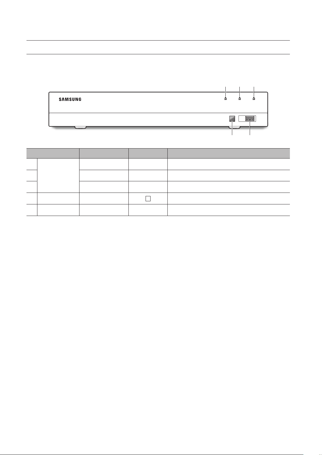
FRONT PANEL
DVR is short for Digital Video Recorder.
Front panel for DVR with 8 channels for SDR-B74301
Type Key or indicator Identification Functions
a b c
REC NET PWR
USB
d e
a
b
c
d
e
HDD indicator REC If the "Red" indicator flashes, the hard drive is being read or written to.
Status lamp
IR port Receive IR signal from Remote Controller.
Net indicator NET Display network connection and data transfer status.
Power indicator PWR If the "Blue" indicator is on, DVR is getting power normally.
USB USB USB port
4_ Overview of DVR
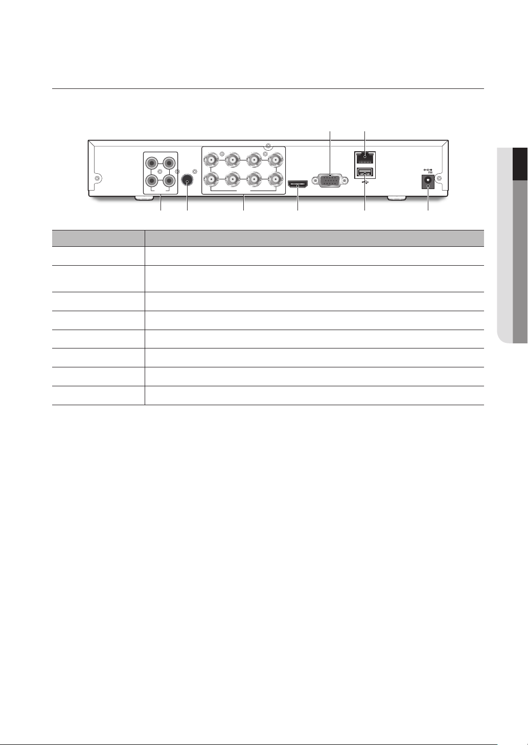
REAR PANEL
Back panel for SDR-B74301
ba
1
2 4
AUDIO
INPUT
3
1 3 5 7
2 4 6 8
AUDIO
OUTPUT
VIDEO
INPUT
HDMI VGA
egh f d c
Physical Interface Connection
VGA port Connect with VGA display devices, such as PC monitor.
a
LAN: (RJ45)
b
Network port
Power port Connect with the power supply DC12V 2A, included with the device
c
USB port Connect with USB.
d
HDMI Connect with HDMI display devices, such as PC monitor.
e
Video input Connect with CH1-8 (analog) video input device, standard BNC port
f
Audio output Audio signal output, RCA port
g
Audio input Connect with CH1-4 audio input signals, RCA port
h
Connect with LAN, Ethernet cable.
LAN
12V
● OVERVIEW OF DVR
English _5
Overview of DVR
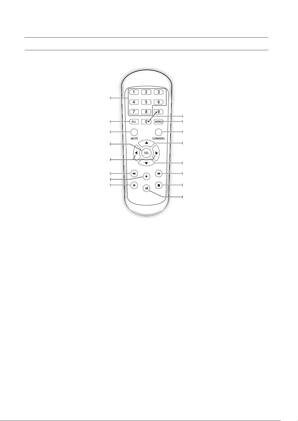
REMOTE CONTROLLER
Operation of remote controller
Channel select 1-8; Numeric key
Multiple display mode
Select key/Edit key
ALL
MUTE
Mute on/off
SEL
Numeric key
MENU
Enter into Main menu/Exit
SUBMENU
Go to Submenu
Up arrow key, volume increase
Left/Right key; Decrease/Increase parameter value of
Enter into record search menu/Play key
control bar.
Rewind key
Record key
Down arrow key, Volume decrease
Forward key
Stop manual record; stop playing
Pause/Step forward key
6_ Overview of DVR

INSTALL HARD DRIVE
1
1 3 5 7
3
2 4
2 4 6 8
AUDIO
OUTPUT
HDMI VGA
LAN
12V
AUDIO
INPUT
VIDEO
INPUT
USB
REC NET PWR
USB
REC NET PWR
1
1 3 5 7
3
2 4
2 4 6 8
AUDIO
OUTPUT
HDMI VGA
LAN
12V
AUDIO
INPUT
VIDEO
INPUT
HDD is pre-installed. If you want to replace hard disk drive, please refer to the following instruction. Please do not remove the hard drive when DVR
`
M
is operating.
Installation of Hard Drive
1. Unplug the DVR to turn the power off. Using a screwdriver, remove the screws from the side and back panels, and then
remove the top cover.
2. Connect data and power cables of hard drive to the motherboard. Mount the hard drive by mounting it onto the rack and
connecting the power and data cables.
Two groups of screw mounting holes are provided on the base frame of the DVR, respectively for installation of a 3.5" hard
drive and 2.5" hard drive. Screw the hard drive in place according to the size of your hard drive.
● OVERVIEW OF DVR
3. Next, screw the back panel in place, and then the sides.
English _7
Overview of DVR
1
1 3 5 7
3
2 4
2 4 6 8
AUDIO
OUTPUT
HDMI VGA
LAN
12V
AUDIO
INPUT
VIDEO
INPUT
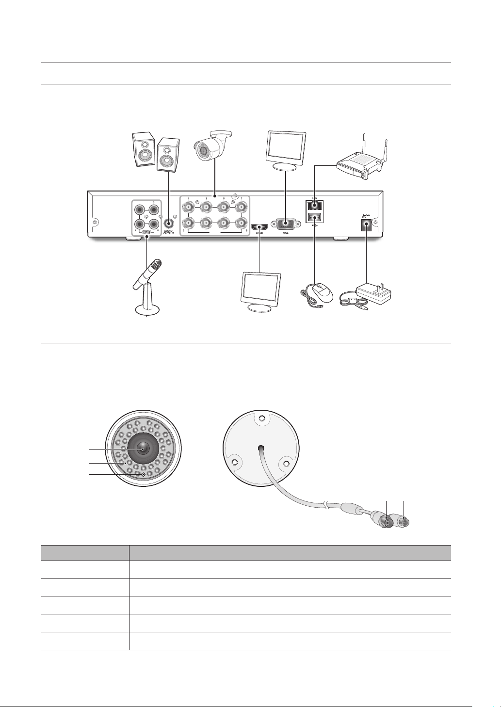
CONNECT EXTERNAL EQUIPMENT
Connect camera signal cable to video input port on the DVR via the BNC connectors. Connect your monitor to the DVR using the
VGA or HDMI video cable. Connect DVR to the power supply adapter provided. After all connections are completed, plug the DVR
in to perform function checks. Be sure that all audio/video I/O ports are connected properly.
CONNECT CAMERA
Connecting the Camera (SDC-9443BC)
Equipped with the IR LED lights and the illumination sensor, the camera enables you to monitor at all times, day and night. The
camera is suitable for both indoor and ourtdoor use.
Do not fully expose the camera to rain. The camera must be installed under a shelter to avoid exposure to excessive rain or moisture.
a
b
c
d e
Name Description
Lens 3.6mm focal length enables you to monitor at a wider field of view
a
IR LED Infrared LED lights are controlled by the illumination sensor.
b
Illumination Sensor Detects incoming light to control the IR LED.
c
BNC Cable BNC terminal for video signal output.
d
Power Cable Use to power the camera.
e
8_ Overview of DVR
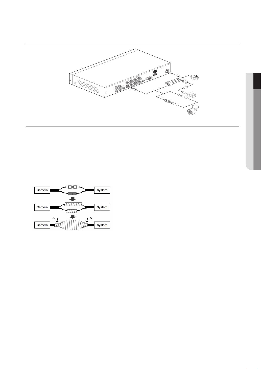
CONNECT DVR
LAN
12V
1
2 4
AUDIO
INPUT
3
AUDIO
OUTPUT
1 3 5 7
2 4 6 8
HDMI VGA
VIDEO
INPUT
PROTECTION OF CABLE FROM WATER
If this product is mounted outdoor, water leakage may occur at gap between cables. As shown below, butyl rubber (available on the
market) shall be used to protect from water.
1. Connect power supply and BNC power source.
2. Cover black sheath of the cable (Zone A), and ensure half of butyl rubber can cover the cable joint.
Poor water protection at the cable sheath may cause water leakage. Make sure to wrap tightly.
`
J
The water-proof butyl rubber is made of rubber that expands to twice the original length.
`
If you do not use cable joint, it must be covered with water-proof tape.
`
● OVERVIEW OF DVR
English _9
Overview of DVR
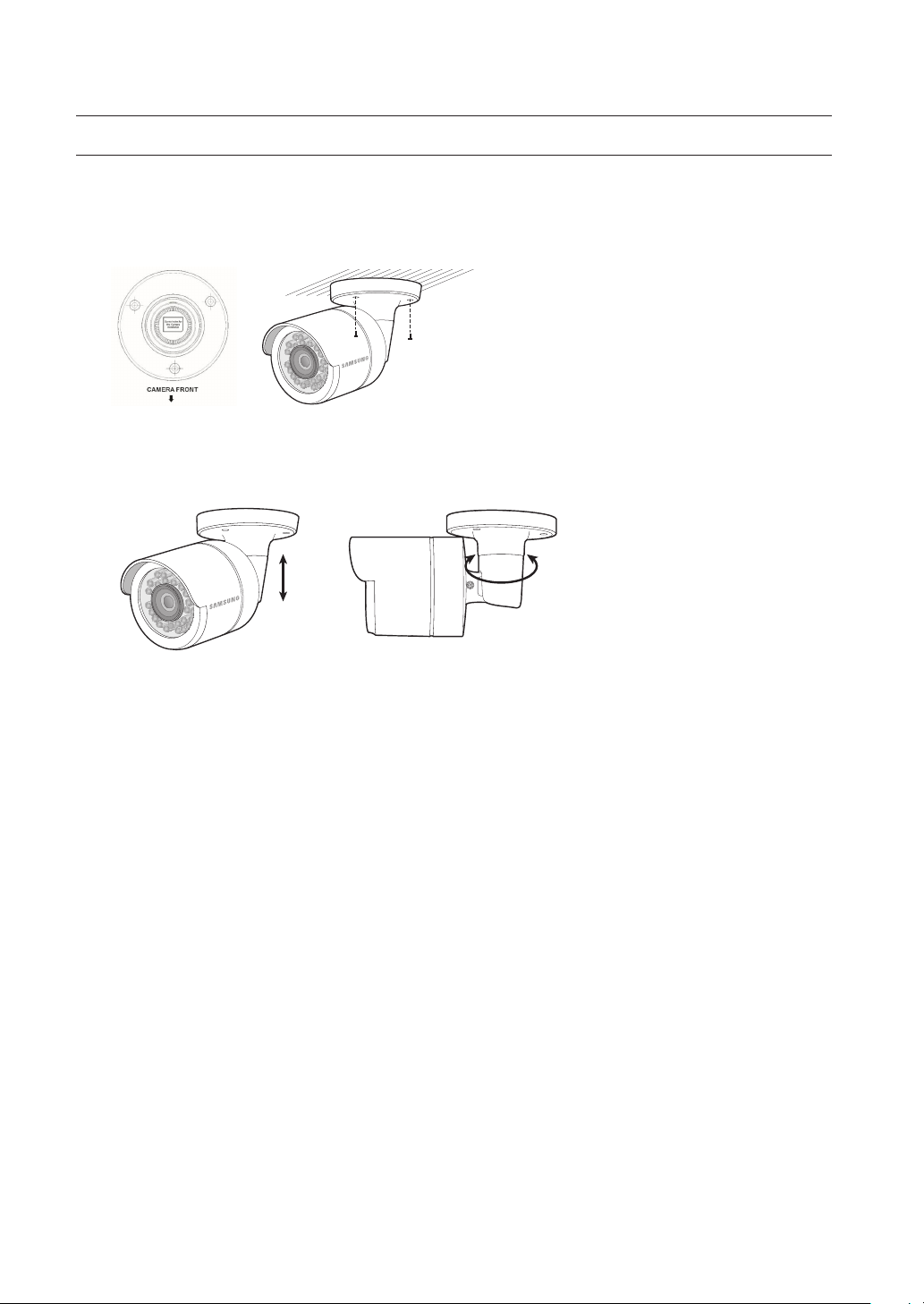
INSTALLING THE CAMERA
The camera can be installed on the wall, ceiling, shelf or a desired position using the provided mounting bracket.
1. Adhere the installation template onto the ceiling and use it as installation locating tool. (Please refer to Page 21 of Quick
Guide.)
2. Choose an installation site that can sufficiently support the weight of the camera to be installed.
3. Attach the camera mount to the wall using the supplied screws.
4. Adjust the direction of the camera to the desired direction, and tighten the bracket.
5. Adjust camera angle as needed.
6. Connect the camera cable to the camera.
Take caution when installing the camera outdoors because the cable connectors may be wet with moisture or pile up with
impurities.
Although the camera is IP66 rated, direct exposure to water or moisture may cause problem such as condensation.
10_ Overview of DVR
DVR Boot up
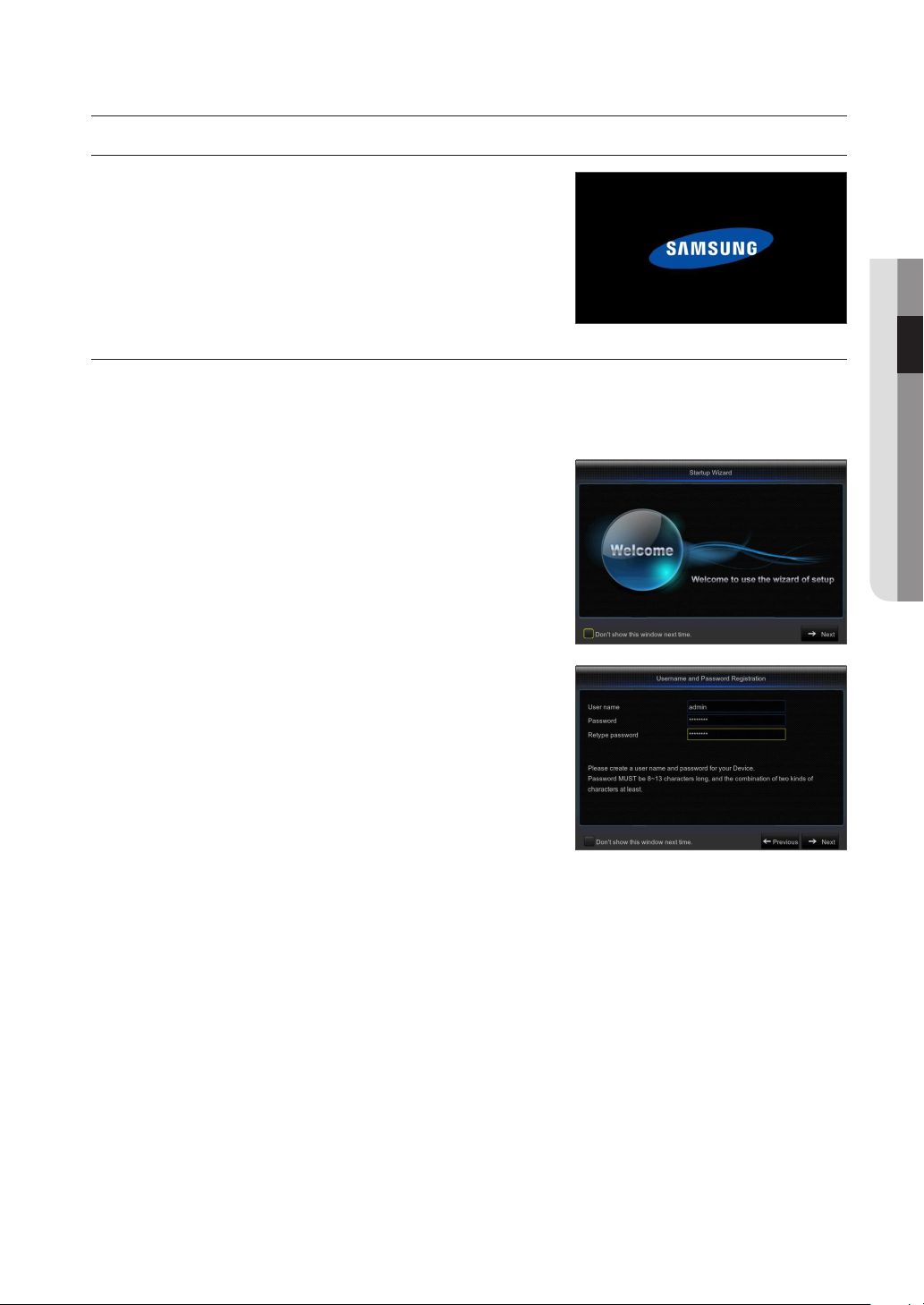
SYSTEM INITIALIZATION
After connecting the DVR power cable to wall outlet, the DVR system initializing
screen will appear.
It may take 40 seconds to start up, and the screen may beep 5~6 times.
`
M
STARTUP WIZARD
After the DVR startup is complete, the startup wizard will display.
Wizard setting menu includes: Homepage, admin password setting, hard drive management, video recording schedule, basic
system configuration, network setup, e-mail and DDNS setting. You can click on "Don't show this window next time" if you do not
wish to have the wizard setting to appear next time.
1. Set Admin Password: Please create a user name and password for your
device. Password MUST be 8~13 characters long, and with at least a
combination of two types of characters.
Retype password: Re-enter the password set above
● DVR BOOT UP
English _11
DVR Boot up
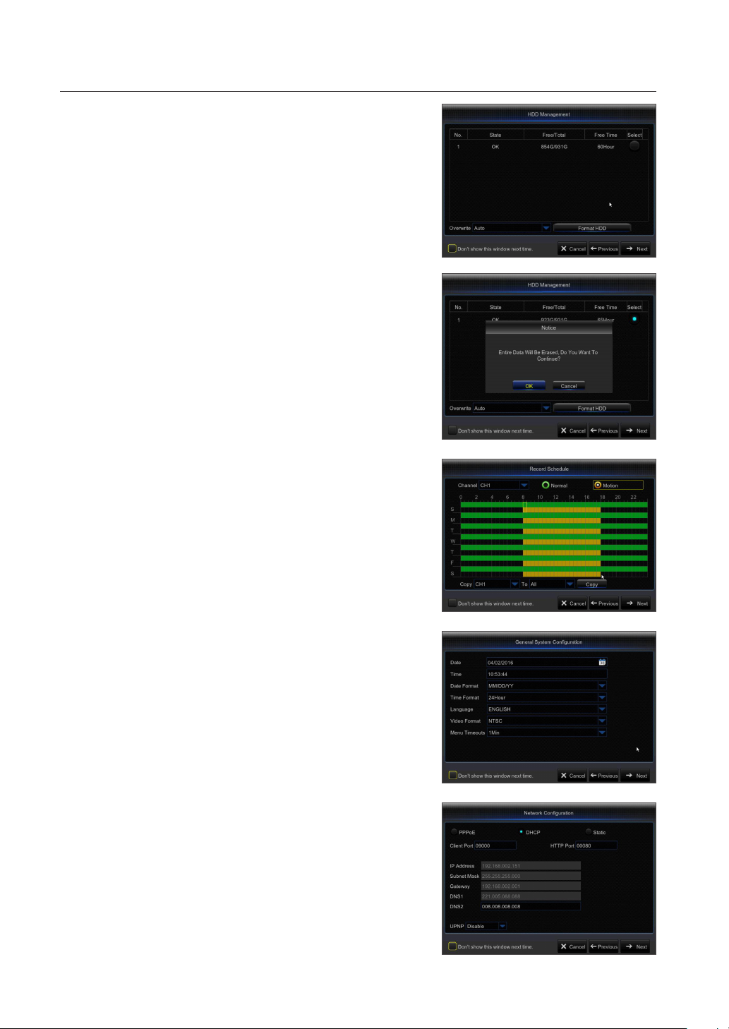
2. Hard Drive Management: Any new disk connected must be formatted before
use. Click on "Select" to highlight the hard drive to be formatted. Click on
"Format HDD" and the user login box will appear. Enter the password to log
in. Click on "OK" to format the disk when the "Entire Data Will Be Erased.
Do You Want To Continue?" dialog box appears. Formatting process is
complete when the progress bar is full.
3. Video Recording Schedule: Select the channel and the date to be set. One
week's schedule can be set.
The record schedule of the current channel can be copied to any other
channel or all channels.
In the Record menu and Record Search menu, when no colors are presented, it means
`
M
there are no recordings during that time.
"Green" stands for normal record and "yellow" stands for motion record.
`
4. General System Configuration: Set the date, time, date format, time format,
language, video format and menu timeouts.
5. Network Configuration (DHCP): In DHCP mode the router will automatically
assign an IP address to DVR. If the DVR fails to obtain an IP address, refer
to the DVR Router Guide. If the problem still cannot be resolved, contact
technical support.
12_ DVR Boot up
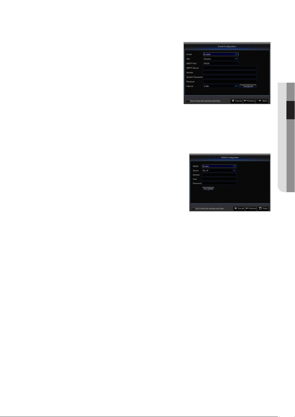
6. Email Configuration: Receive or Send DVR alerts via email.
•
SSL (Secure Socket Layer): This is an industry standard transport
protocol that establishes an encrypted link between the web server and
browser. This link ensures that all data that passes between the web server
and browser remains private and integral. If the setting is incorrect, check
you mail server's SMTP port
•
SMTP Port: The mail sending port used by SMTP (Simple Mail Transfer
Protocol) server is generally Port 25, or Port 465.
•
SMTP Server: Enter address of the mail server you want to connect to.
•
Sender address: Enter sender's mail address, which must correspond to
the server used.
For example, mailbox "aaa@gmail.com" should correspond to server "smtp.gmail.com".
•
Recipient address: Recipient's mail address, used to receive alarm image and message from DVR side. If system alarms
continually and sends Email images frequently, save the images to another location or remove them, so as to avoid
excessive space occupation and thereby affect your normal use of mailbox.
•
Time interval: A mail will be sent every three minutes by default. If the time interval for mail notification is set too short,
email server may deem mails as junk mails, so they cannot be transferred normally.
7. DDNS SETTING. User may set DDNS under network type of PPPoE/Static/
DHCP after applying dynamic domain service. User may remotely access DVR
through domain by using browser in the form of http://applied domain: mapped
HTTP port number when using DDNS domain name to access DVR.
•
Server address: Select dynamic domain name server provider. Available
domain name servers (DDNS_3322, DYNDNS, NO_IP, CHANGEIP, DNSEXIT)
•
Host name: dynamic domain name of the host obtained from dynamic
domain name service provider upon registration, for example, dvr2016.no-ip.
org
•
User Name: The user name registered upon application for dynamic domain
name.
•
Password: The password set upon registration.
•
Click on "Test DDNS". If connection succeeds, it will be indicated that "DDNS Test is Successful!
Perform remote access to DVR by using dynamic domain name, for example, http://dvr2016.no-ip.org: HTTP port number
(e.g. 19010)
8. Click on "Save" to finish setting of startup wizard.
● DVR BOOT UP
English _13

DVR Boot up
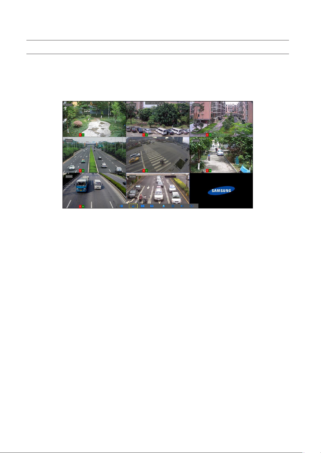
MAIN INTERFACE
In real-time preview mode: right click on any area to access the desired menu. Right click on it to open a context menu, whose menu
items may vary depending on the specific condition, such as sign-in, sign-out, split screen mode and various operation conditions.
Left click on any channel to access shortcut menu, where operations such as image capture, recording and image zoom-in are
available.
a b c d
e fghi
j k l m n o p q
The video recording marks are as shown below:
R
means common Recording.
M
means Motion detection recording.
M
means Motion detection without recording.
Component Name Function
Camera Type A means AHD camera. Absence of it means 960H camera.
a
Date & Time Display current date and time
b
Channel Name Display channel name
c
SAMSUNG Logo The logo of SAMSUNG will display only when video is loss.
d
Image Capture Make a snapshot of current video
e
Manual Recording Enable or disable manual recording
f
Quick Playback Make playback of the last 5 minutes of the video
g
Electronic Zoom-In Hold and drag mouse cursor to select a frame of current video to zoom in.
h
Channel Color Setting Set hue, brightness, contrast and saturation of current channel.
i
Main Menu Access the main menu
j
14_ DVR Boot up
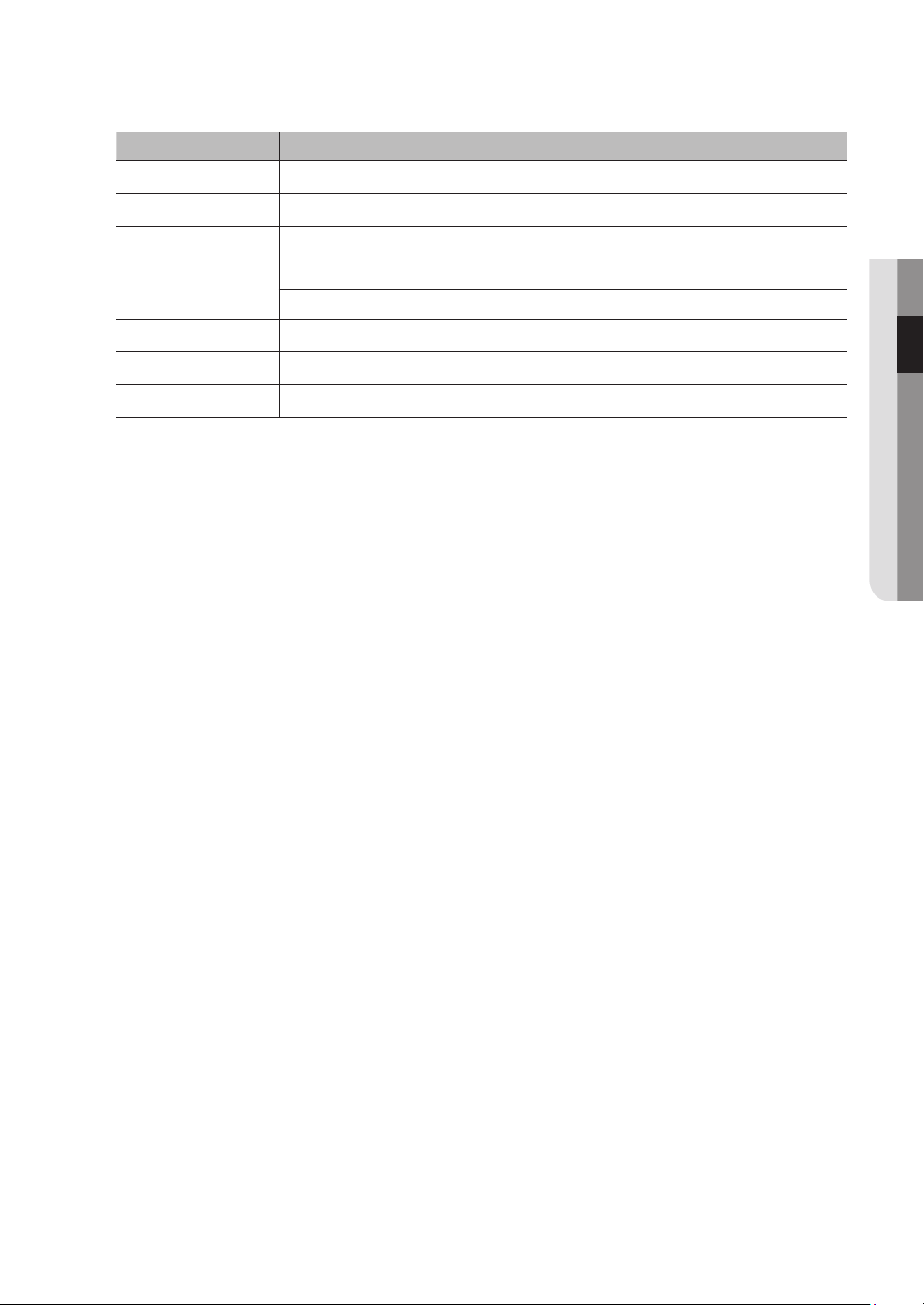
Component Name Function
Lock Sign out or access sign-in page.
k
Four-Channel Layout Display four channels of video.
l
Nine-Channel Layout Display nine channels of video.
m
N-Channel Layout
n
Polling Start or stop polling.
o
Sound Adjust volume or mute.
p
Playback Access video retrieval page.
q
Display six channels of video.
Display eight channels of video.
● DVR BOOT UP
English _15
DVR Menu
POPUP MENU
After finishing system initialization, right click the mouse on preview interface or slide the mouse to the bottom of screen to enter
into Pop-up Menu. Now you could perform parameter setting and operate on Main Menu, Multi-screen, Record Search, Sequence,
Volume and Brightness settings.
The options in the pop-up menu may vary slightly according to different parameter settings and application environment. The options
in the menu will be explained in detail in the following chapters.
16_ DVR Menu

MAIN MENU GUIDE
Display
Record
Live
Output
Private Zone
● DVR MENU
Record
Record Schedule
Main stream
Substream
Main Menu
Parameter
Record Search
Device
System
Capture
Network
Alarm
General
Events
Picture
HDD
Cloud Storage
General
Users
Info
Log
Capture
Capture Schedule
Network
Email
Email Schedule
DDNS
RTSP
FTP
Motion
General
DST
NTP
Advanced
Shutdown
Maintain
Events
English _17
DVR Menu
MAIN MENU
On LIVE mode, click the mouse button, or [Menu] button on the remote controller, or click [ ] icon on the toolbar to enter the main
menu screen.
If system interface is locked, refer to section 3.3 to unlock by entering your password.
In Main Menu mode, you can make settings for Parameter, Record Search, Device, System, Advanced and Shutdown.
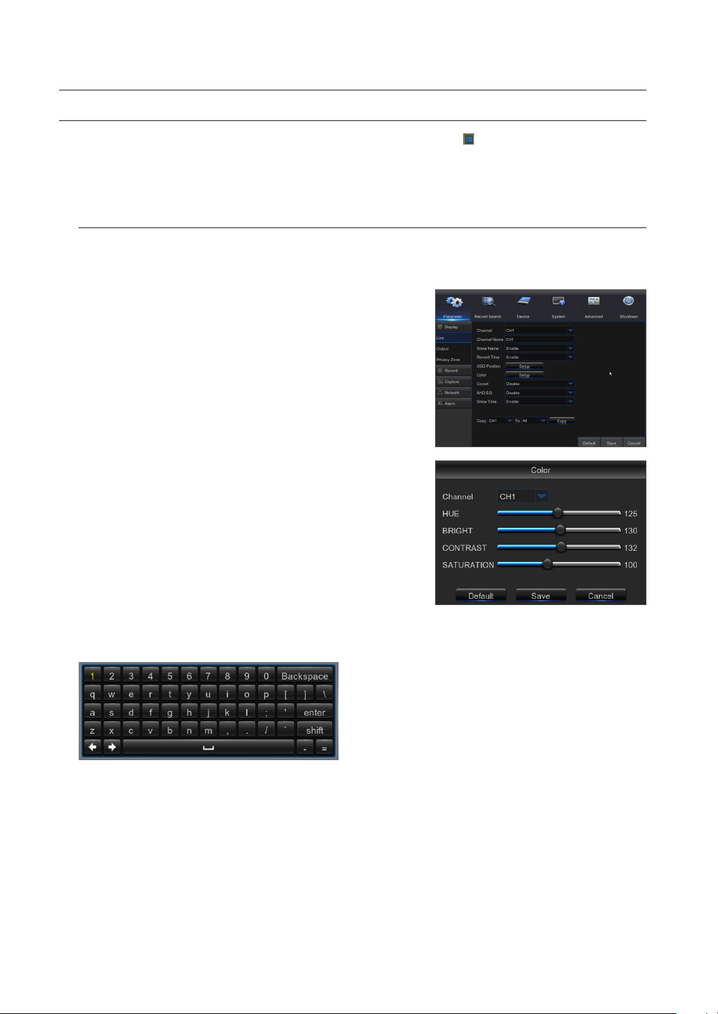
Parameter
Live
Go to "Main Menu" ; "Parameter" ; "Display" ; "Live"
•
Channel: Select the channel in the drop-down list.
•
Channel Name: Channel name, support up to 8 characters.
•
Show Name: Showing Channel name
•
Record Time: Enable or disable displaying system time in recording.
•
OSD Position: Adjustment the position of channel name and time display
•
Color: Click "Setup" to access the color settings
•
Covert: Enable/Disable Video hiding.
•
AHD EQ: Switch of AHD signal equalizer.
•
Show Time: Enable or disable the time displayed in the live interface.
•
Copy: Copy the parameters in the channel to any other channel or all
channels.
Adjust the brightness, hue, contrast and saturation of the image in selected
channel in "Live" interface.
To modify the parameter value in sub-menu and make it effective, click "Save" after
`
M
modification and a dialog box with message "Save parameters successful!" will pop up.
Click "OK" in the interface, then "Exit" to exit the menu. If you want to cancel the
modification, click "Cancel" to exit.
Use Virtual Keyboard
Virtual keyboard window will be displayed for input. Click on the desired characters to apply them. Press <Shift> to switch to
input of upper-case letters.
Press <Shift> again to switch to input of special characters. The virtual keyboard is used in the same way as with physical
keyboard.
For input of password, use letters and special characters other than <\> and <">.
18_ DVR Menu
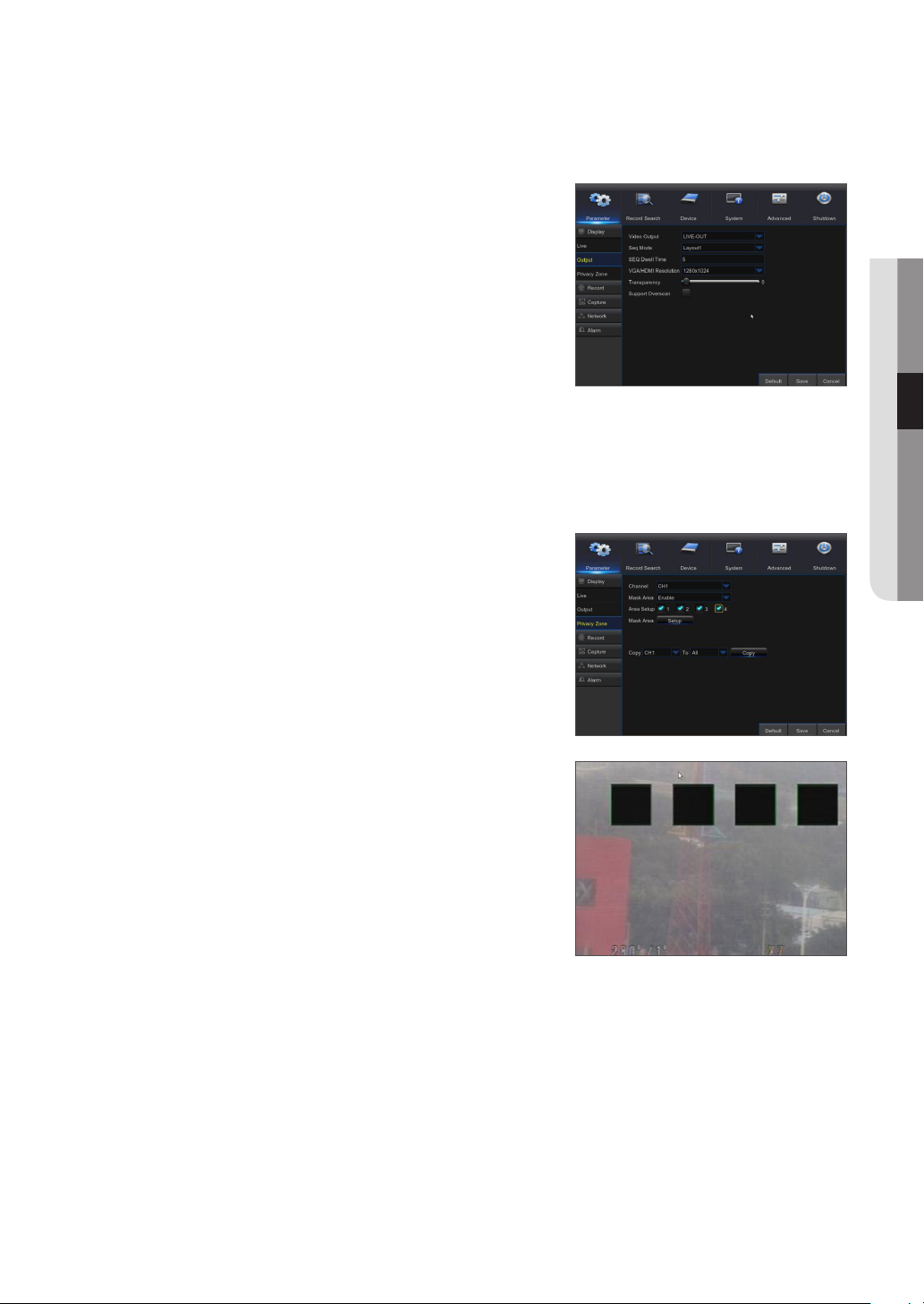
Output
Go to "Main Menu" ; "Parameter" ; "Display" ; "Output" to enter into the interface.
•
Video Output: Live Output
•
Sequence Mode: layout1, layout4, layout6
•
SEQ Time: Sequence time is set 5 seconds by default. User may set it as
required up to 300 seconds
•
VGA/HDMI Resolution: For VGA output or HDMI output, the optional
resolution includes 1024×768, 1280×1024, 1440×900, 1280×720,
1920×1080
•
Transparency: Adjust menu transparency in the range of 0-128.
•
Support Overscan: Support HDMI overscan
Private Zone
Go to "Main Menu" ; "Parameter" ; "Display" ; "Private Zone" to enter into the interface.
Privacy Zone is to block certain area(s) in the camera's field of view from recording in the selected channel.
1. Select the number of the zone(s) to be blocked (maximum of 4 zones can
be set for single channel)
2. Click "Setup" to adjust the position of the zone.
3. After finish setting, right click the mouse to return to the "Privacy Zone"
page.
4. Click "Save" to save the setting.
● DVR MENU
English _19
 Loading...