


SyncMaster 400MX-3, 460MX-3, 400FP-3, 460FP-3
LCD Display
User Manuals
The color and the appearance may differ depending on the
product, and the specifications are subject to change
without prior notice to improve the performance.

Safety Instructions
Notational
Note
These safety instructions must be followed to ensure your safety and prevent property damage.
Make sure to read the instructions carefully and use the product in the correct manner.
Warning / Caution
Failure to follow directions noted by this symbol could result in bodily harm
or damage to the equipment.
Note
Power
Prohibited
Do not disassemble
Do not touch
When not used for extended period of time, set your computer to DPM.
If using a screen saver, set it to active screen mode.
The images
countries).
Shortcut to Anti-Afterimage Instructions
here are for reference only, and are not applicable in all cases (or
Do not use a damaged power cord or plug or a damaged or loose power
outlet.
• Otherwise, this may result in electric shock or fire.
Important to read and understand at all times
Disconnect the plug from the
outlet
Ground to prevent an electric
shock
Do not touch the power plug with wet hands when removing or plug-
ging the plug into the outlet.
• Otherwise, this may result in electric shock.
Make sure to connect the power cord to a grounded power outlet.
• Otherwise, it may result in electric shock or personal injury.
Ensure that the power plug is plugged into the power outlet firmly and
correctly.
• Otherwise, this may result in fire.

Safety Instructions
Do not forcefully bend or pull the power plug and do not place any
heavy material on it.
• Otherwise, this may result in fire.
Do not connect multiple appliances to the same power outlet.
• Otherwise, this may cause fire due to overheating.
Do not disconnect the power cord while using the product.
Installation
• Otherwise, this
shock.
To disconnect the apparatus from the mains, the plug must be pulled
out from
erable.
• Otherwise, this may cause electric shock or fire.
provided power cord of another product.
• Otherwise, this may result in fire or electric shock.
• When
Be sure to contact an authorized Service Center
a location with heavy dust, high or low temperatures, high humidity, and exposed
to chemical substances and where it operates for 24 hours such as at airports,
train stations etc.
the mains socket, therefore the mains plug shall be readily op-
Use only the power cord provided by our company. Do not use the
Connect the power plug to a wall outlet that can be easily reached.
problem occurs with the product, you must unplug the power
a
plug to cut the power off completely. You cannot cut the power off
completely using only the power button on the product.
may result in damage to the product due to electric
installing your monitor in
when
Failure to do so may cause serious damage to your monitor.
Ensure that at least two persons lift and move the product.
• Otherwise,
age the product.
When installing the product in a cabinet or rack, make sure that the
front end of the bottom of the product does not project out.
• Otherwise, it may fall or cause personal injury.
Use a cabinet or rack of a size appropriate to the product.
•
DO NOT PLACE CANDLES, MOSQUITO REPELLANT, CIGARETTES AND
UCT.
• Otherwise, this may result in fire.
may be dropped and cause personal injury, and/or dam-
it
ANY HEATING APPLIANCES NEAR THE PROD-

Safety Instructions
Keep heating appliances as far away from the power cord or the product as possible.
• Otherwise, this may result in electric shock or fire.
Do not install it in a badly ventilated location such as a bookcase or
closet.
• Otherwise, this
temperature.
When putting the product down, make sure to put it down softly.
• Otherwise, this may result in damage to the screen display.
Do not place the front of the product on the floor.
• Otherwise, this may result in damage to the screen display.
Ensure that an authorized installation company installs the wall mount.
• Otherwise, it may fall and cause personal injury.
Make sure to install the specified wall mount.
•
Install your product in a well ventilated location. Ensure that there is
a clearance of more than 4 inches (10 cm) from the wall.
• Otherwise, it
perature.
Bend the outdoor antenna cable downwards at the location where it
goes in so that rainwater does not flow in.
may result in fire due to an increase in the internal
may result in fire due to an increase in the internal tem-
Clean
• If rainwater
Install the antenna far away from any high voltage cables.
• If
the
in electric shock or fire.
Ensure that the packaging vinyl is kept away from children.
• Otherwise,
with it.
If the height of your monitor is adjustable, do not place any object or
part of your body on the stand when lowering it.
• This may cause damage to the product or the person carrying it.
When cleaning the monitor case or the surface of the TFT-LCD screen, wipe
with a slightly moistened, soft cloth.
enters the product, it may result in electric shock or fire.
antenna touches or falls onto a high voltage cable, it may result
it
may result in serious harm (suffocation) if children play

Safety Instructions
Do not spray cleaner directly onto the surface of the product.
• Otherwise, this
structure and the screen surface may peel off.
When cleaning the power plug pins or dusting the power outlet, clean
it with a dry cloth.
• Otherwise, it may result in fire.
When cleaning the product, make sure to disconnect the power cord.
• Otherwise, it may result in electric shock or fire.
When cleaning the product, disconnect the power cord and clean it
with a soft, dry cloth.
• (Do
specified cloth only.
not use chemicals such as wax, benzene, alcohol, thinner, mosquito repellant, lubricant, or cleaner.) These may change the appearance of the product surface and peel off the indication labels on the
product.
Since the product housing is easily scratched, make sure to use the
may result in the discoloration and distortion of the
Others
When cleaning the product, do not spray water directly onto the main
body of the product.
• Ensure that water does not enter the product and that it is not wet.
• Otherwise, this may result in electric shock, fire or a malfunction.
The product is a high voltage product. Do not disassemble, repair or
modify the product yourself.
• Otherwise, this
needs to be repaired, contact a Service Center.
If there is a strange smell or a strange sound or smoke is coming from
the product,
Center.
• Otherwise, this may result in electric shock or fire.
Do not place this product in a location exposed to moisture, dust,
smoke, water, or in a car.
• Otherwise, this may result in electric shock or fire.
disconnect the power plug immediately and contact a Service
may result in electric shock or fire. If the product
When you drop the product or the case is broken, turn the power off
and disconnect the power cord. Contact a Service Center.
Otherwise, this may result in electric shock or fire.
•

Safety Instructions
If thunder or lightning is occurring, do not touch the power cord or
antenna cable.
• Otherwise, this may result in electric shock or fire.
Do not try to move the monitor by pulling only the wire or the signal
cable.
• Otherwise, it
product or fire due to damage to the cable.
Do not lift or move the product back and forwards or right and left
while only holding the power cord or signal cables.
• Otherwise, it
product or fire due to damage to the cable.
Make sure that the ventilating opening is not blocked by a table or
curtain.
• Otherwise, it
perature.
Do not place any containers containing water, vases, flowerpots, medicines as well as any metal on the product.
• If water
cord and contact a Service Center.
• This may result in a product malfunction, electric shock, or fire.
Do not use or keep combustible spray or flammable material near the
product.
• Otherwise, this may result in an explosion or fire.
may fall and result in electric shock, damage to the
may fall and result in electric shock, damage to the
may result in fire due to an increase in the internal tem-
or a foreign material enters the product, disconnect the power
Do not insert any metal, such as chopsticks, coins, pins and steel, or
flammable objects, such as matches or paper, inside the product (through
the ventilating openings, input and output terminals, etc).
• If water or foreign material enters the product, disconnect the power
cord and contact a Service Center.
• Otherwise, this may result in electric shock or fire.
When using a fixed screen for a long time, an afterimage or stain may
occur.
• If you are not using your product for a long period of time, put it into
sleep mode or use a moving screen saver.
Set a resolution and frequency appropriate to the product.
• Otherwise, your eyesight may be damaged.
When using headphones or earphones, do not turn the volume too high.
•
Having the sound too loud may damage your hearing.

Safety Instructions
To avoid eyestrain, do not sit too close to the product.
Take a rest for at least five (5) minutes after using the monitor for one
(1) hour.
This reduces eye fatigue.
Do not install it in an unstable location such as an unstable rack or
uneven surface or a location exposed to vibrations.
• Otherwise, it
product.
• If you use the product in a location exposed to vibrations, it may
damage the product and result in fire.
When moving the product, turn the power off and disconnect the power
plug, antenna cable, and all the cables connected to the product.
• Otherwise, it may result in electric shock or fire.
Ensure that children do not hang onto the product or climb up onto the
product.
•
The product may fall and cause personal injury or death.
If you do not use the product for a long period of time, disconnect the
power cord from the power outlet.
• Otherwise,
result in fire due to electric shock or leakage.
Do not place any heavy items or toys or confectionery, such as cookies
etc. that may attract the attention of children and to the product.
• Your
removed
children or infants cannot reach.
children
may result in personal injury or death.
Be careful that children do not place the battery in their mouths when
from
may fall and cause personal injury and/or damage the
this
may result in overheating or fire due to dust, and may
may hang onto the product causing it to fall and this
the remote control. Place the battery in a location that
• If children have had the battery in their mouths, consult your doctor
immediately.
When replacing the battery, insert it with the right polarity (+, -).
• Otherwise,
personal injury or damage due to leakage of the internal liquid.
Use only the specified standardized batteries, and do not use a new
battery and a used battery at the same time.
• Otherwise, the
jury or damage due to a leakage of the internal liquid.
battery may become damaged or it may cause fire,
the
batteries may be damaged or cause fire, personal in-
Safety Instructions
The batteries (and rechargeable batteries) are not ordinary refuse and
must be
returning the used or rechargeable batteries for recycling.
• The customer can return used or rechargeable batteries to a nearby
near any heat such as a fire or heater.
• This may reduce the lifetime of the product, and may result in fire.
product.
• Otherwise, this may result in electric shock or fire.
• Otherwise, this may result in electric shock or fire.
returned for recycling purposes. The customer is responsible for
public recycling center or to a store selling the same type of the battery
or rechargeable battery.
Do not place the product in a location exposed to direct sunlight or
Do not drop any objects onto the product or cause any impact to the
Do not use a humidifier near the product.
When there is a gas leak, do not touch the product or the power plug;
ventilate immediately.
• If a spark occurs, it may cause an explosion or fire.
If the product has been turned on for a long time, the display panel
becomes hot. Do not touch it.
Keep the small accessories in a location out of the reach of children.
Be careful when adjusting the angle of the product or the height of the
stand.
• This may
come caught.
• Also, if you tilt the product too far, it may fall and cause personal
injury.
Do not install the product in a location low enough for children to
reach.
result in personal injury as your hand or fingers may be-
• Otherwise, it may fall and result in personal injury.
Since the front part of the product is heavy, install the product on a
•
level and stable surface.
Do not put any heavy objects on the product.
• This may result in personal injury and/or damage to the product.

Introduction
Package Contents
Checking the Contents of the Package
Remove the lock from the package box, as shown in the figure above.
holding the grooves on both
•
•
• If any items are missing, contact your dealer.
• Contact a local dealer to purchase optional items.
Unpacking
Lift up the package box by
sides of the package box.
Note
After unpacking the package, make sure to check the contents of the package.
Store the packaging box in case you need to move the Product later.
Check the contents of the
package.
Remove the Styrofoam and
vinyl cover.
LCD Display

Manuals
Introduction
Quick Setup Guide Warranty Card
(Not available in all loca-
Cables
Power Cord D-Sub Cable
Others
Remote Control
Batteries (AAA X 2)
User's Guide
tions)
(BP59-00138B)
Sold separately
Semi Stand KIT LAN Cable USB Cable
RGB to BNC Cable RGB to COMPONENT Ca-
(Not available in all loca-
tions)
ble
Network Box

Sold separately
Wall Mount KIT TV Tuner box RS232C Cable
Your LCD Display
Introduction
Front
The color
to change without prior notice to improve the performance.
and the appearance may differ depending on the product, and the specifications are subject
MENU button [MENU]
Opens the
or return to the previous menu.
Navigate buttons (Up-Down buttons)
on-screen menu and exits from the menu. Also use to exit the OSD menu
Moves from
Adjust buttons (Left-Right buttons) / Volume buttons
Moves from one menu item to another horizontally or adjusts selected menu values. When OSD is not on the screen, press the button to adjust volume.
ENTER button [ENTER]
Activates a highlighted menu item.
SOURCE button [SOURCE]
Switches from PC mode to Video mode. Selects the input source that an external
device is connected to.
[PC] → [
playPort] → [MagicInfo] →[TV]
Note
• The [RGB/COMPONENT IN] port is compatible with RGB (PC) and Component signals.
However, the picture may display abnormally if the connected external input
signal is different from the selected video signal.
• MagicInfo can only be enabled when a network box is connected.
one menu item to another vertically or adjusts selected menu values.
DVI] → [AV] → [Component] → [HDMI1] → [HDMI2] → [Dis-
• A TV tuner box (sold separately) must be connected to use the TV.

D.MENU button
Opens the on-screen D.MENU.
Note
Introduction
The D.MENU
PIP button is enabled.
PIP button
Push the PIP button to turn the PIP screen On / Off.
Power button [ ]
Use this button for turning the LCD Display on and off.
Brightness Sensor
Automatically detects the surrounding brightness.
Note
This function does not work for this LCD Display.
Power indicator
Shows PowerSaver mode by blinking green
Note
See PowerSaver
saving functions. For energy conservation, turn your LCD Display OFF when it
is not needed or when leaving it unattended for long periods.
Remote Control Sensor
button is activated when a TV tuner is connected and otherwise, the
described in the manual for further information regarding power
Rear
Aim the remote control towards this spot on the LCD Display.
Note
See the
at the back may vary slightly depending on the model.
"Connections" section for details about cable connections. The LCD Display's configuration

Introduction
POWER S/W ON [
Switches the LCD Display On/Off.
POWER
The power
the wall outlet.
RGB/COMPONENT IN
Connection Terminal (Input))
• Connect the [RGB/COMPONENT IN] port
on the monitor to the RGB port on the PC using the D-SUB cable.
• Connect the [RGB/COMPONENT IN] port
on the monitor to the COMPONENT port on
the external device using the RGB to COMPONENT cable.
• Connect the [RGB/COMPONENT IN] port
on the monitor to the BNC port on the PC using the RGB to BNC cable.
cord plugs into the LCD Display and
│
] / OFF
(PC/COMPONENT
DVI IN (PC Video Connection Terminal)
Connect the [
DVI port on the PC using the DVI cable.
RGB/DVI/DP/HDMI AUDIO IN (PC/DVI/
DP/HDMI Audio Connection Terminal (Input))
Connect the [
terminal of the monitor and the speaker output
terminal of your computer's sound card using a
stereo cable (sold separately).
DP IN
Receives a signal from the Display port.
Connect a
DP IN on another display.
DVI IN] port on the monitor to the
RGB/DVI/DP/HDMI AUDIO IN]
DP cable to [DP IN] on the product and

Introduction
AV/COMPONENT AUDIO
Connect the [AV/COMPONENT AUDIO IN [L-
AUDIO-R]] port on the monitor to the audio
output port on the PC or on the external device
using an audio cable.
AV IN
Connect the [AV IN] terminal
the video output terminal of the external device
using a VIDEO cable.
AUDIO OUT
Connect a headphone or an External speaker.
DC OUT
Make sure
to the authorized TV-Tuner Box[SBB_DTC/
ZA].
to use connecting [DC OUT] terminal
IN [L-AUDIO-R]
of your monitor to
Otherwise, this may result in damage to
the product.
HDMI IN 1
• Connect the [
of your LCD Display to the HDMI terminal
of your digital output device using a HDMI
cable.
• Up to HDMI 1.3 can be supported.
Note
• A normal
camcorder, etc.) or a TV tuner box can be
connected to the [HDMI IN 1] terminal.
• To use a TV tuner box, make sure to connect
it to the [HDMI IN 1] terminal.
HDMI IN 2 (MAGICINFO)
• Connect the [
terminal at the back of your LCD Display to
the HDMI terminal of your digital output device using a HDMI cable.
HDMI IN 1] terminal at the back
external device (DVD player or
HDMI IN 2 (MAGICINFO)]
• Up to HDMI 1.3 can be supported.
Note
To use MagicInfo, the network box specified
separately by Samsung must be installed inside
Introduction
the product and the MagicInfo output
work box must be connected to the [HDMI IN 2
(MAGICINFO)] terminal.
For more information on how to purchase and install a network box, contact Samsung Electronics.
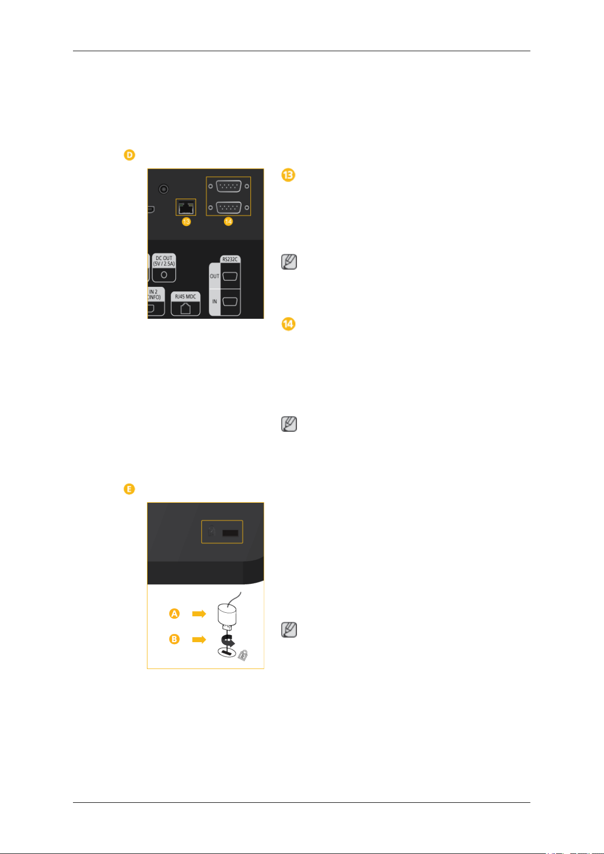
RJ 45 MDC (MDC PORT)
MDC(Multiple Display Control) Program Port
Connect the
product and LAN on the PC. To use an MDC, the
MDC Program must be installed on the PC.
Note
Go to Multi
the MDC Connection.
RS232C OUT/IN (RS232C Serial PORT)
MDC(Multiple Display Control) Program Port
Connect a
on the product and RS232C on the PC. To use an
MDC, the MDC Program must be installed on the
PC.
LAN cable to [RJ45 MDC] on the
Control and select RJ45 MDC as
serial cable (cross type) to [RS232C]
of the net-
Note
Go to Multi
as the MDC Connection.
Kensington Lock slot
A Kensington
enables users to lock the product so that they can
safely use it in public locations. Since the shape
and usage of the locking device may differ depending on the model and the manufacturer, for
more information, refer to the User Manual supplied with the locking device for more information.
Note
You must
rately.
Control and select RS232C MDC
Lock is an anti-theft device that
purchase the Kensington Lock sepa-
To lock the product, follow these steps:
1. Wrap the Kensington lock cable around a
large, stationary object such as a desk or
chair.

Introduction
2. Slide the end of the cable with the lock at-
tached
through the looped end of the Ken-
sington lock cable.
3. Insert the Kensington Lock into the security
slot (
4.
Lock the lock ( ).
Note
• These are
structions, see the User Manual supplied with
the locking device.
• You can purchase the locking device from an
electronics store, an online shop, or our service Center.
Connecting a Network Box (sold separately)
RGB OUT
MagicInfo video output port
MAGICINFO OUT
This is
and control signals of MagicInfo.
the output terminal for the video, audio,
) on the back of the display.
general instructions. For exact in-
It can be used by connecting it to the [HDMI IN
2 (MAGICINFO)] terminal using an HDMI cable.
LAN (LAN Connection Terminal)
Connects to
work access in MagicInfo mode.
Connecting a Network Box (sold separately)
USB (USB Connection Terminal)
Keyboard / Mouse, Mass Storage Device Compatible.
AUDIO OUT
Connect a headphone or an External speaker.
RS232C (RS232C Serial PORT)
Serial port
Connecting a Network Box (sold separately)
a LAN cable to allow Internet or net-

Introduction
POWER
Note
• See the "Connections" section for details about cable connections.
The power switches of both of the monitor and the network box must be turned on for the network
•
box to operate normally.
Remote Control
Note
The performance
near the LCD Display , causing a malfunction due to interference with the frequency.
Connect the [
and the [POWER] terminal of the monitor using
a power extension cable.
POWER
Connects to a mains socket via the power cord.
POWER S/W ON [ I ] / OFF
Turns the network box on or off.
of the remote control may be affected by a TV or other electronic device operating
POWER] terminal of the product
POWER
OFF
Number Buttons
DEL / GUIDE button
+ VOL -
SOURCE
D.MENU
TOOLS
Up-Down Left-Right buttons
INFO
The Color button and the PC/DVI/HDMI/DP
selection button.
TTX/MIX
MTS/DUAL
ENTER/PRE-CH
MUTE
CH/P
TV

Introduction
MENU
RETURN
EXIT
MagicInfo
POWER
OFF
Number Buttons
DEL / GUIDE button
+ VOL -
SOURCE
Turns the product On/Off.
Turns the product Off.
to
Used
MagicInfo.
Press to change the channel.
The "-" button is used to select Digital channels.
Electronic Program Guide (EPG) display.
This button
(sold separately) is connected.
Adjusts the audio volume.
Selects a connected external input source or MagicInfo mode.
Press the button to change the input signal SOURCE.
enter the password during the OSD adjustment or to use
Note
can only be used in TV mode while a TV tuner box
D.MENU
TOOLS
Up-Down Left-Right but-
tons
INFO
The Color button and the
PC/DVI/HDMI/DP selection
button.
Changing the
are connected to the LCD Display at the time.
DTV menu display
Note
This button
(sold separately) is connected.
Use to quickly select frequently used functions.
Note
This function does not work for this LCD Display.
Moves from
adjusts selected menu values.
Current picture
of the screen.
In TV mode, these buttons can be used to configure a list of channels.
SOURCE is only allowed for external devices that
can only be used in TV mode while a TV tuner box
one menu item to another horizontally, vertically or
information is displayed on the upper left corner

Introduction
TTX/MIX
MTS/DUAL
You can select the PC, DVI, HDMI or DP
input directly in a mode other than TV mode.
TV channels provide written information services via teletext.
- Teletext Buttons
Note
This function does not work for this LCD Display.
MTS-
You can select MTS (Multichannel Television Stereo) mode.
Audio Type MTS/S_Mode Default
FM Stereo Mono Mono Manual Change
Stereo
SAP
DUAL-
Mono ↔ Stereo
Mono ↔ SAP
(DisplayPort) external
Mono
ENTER/PRE-CH
MUTE
CH/P
STEREO/MONO,
MONO/NICAM STEREO can be operated depending on the
broadcasting type by using the DUAL button on the remote control
while watching TV.
Note
Enabled when a TV tuner box is connected.
This button
Note
Enabled when a TV tuner box is connected.
Pauses (mutes)
the lower left corner of the screen. The audio comes back on if
MUTE or - VOL + is pressed in the Mute mode.
In TV mode, selects TV channels.
Note
Enabled when a TV tuner box is connected.
is used to return to the immediately previous channel.
DUAL
the audio output temporarily. This is displayed on
l / DUAL ll and MONO/NICAM
TV
MENU
Allows you to watch an analogue or digital TV.
Note
Enabled when a TV tuner box is connected.
Opens the
adjustment menu.
on-screen menu and exits from the menu or closes the

Introduction
RETURN
EXIT
MagicInfo
User Installation Guide
Note
• Be sure to call an installation expert of Samsung Electronics to install the product.
•
The warranty becomes invalid if the product is installed by someone other than a professional
authorized by Samsung Electronics.
• A Samsung Electronics service center can provide details.
Tilt Angle and Rotation
Returns to the previous menu.
Exits from the menu screen.
MagicInfo Quick Launch Button.
Note
Enabled when a Network box is connected.
1
1. The product can be tilted up to 15 degrees from a vertical wall.
2. To use
the product in portrait mode, rotate it clockwise so that the LED indicator is at the bottom.
Ventilation requirement
2
1. Vertical wall mount condition
<Side view>

Introduction
A : min. 40 mm
B: Ambient temperature Measuring point < 35°C
• When installing the product onto a vertical wall, be sure there is a 40 mm space or more behind
the
product for ventilation, as shown above, and maintain the ambient temperature at 35°C or lower.
Note
A Samsung Electronics service center can provide details.
2. Embedded Mount guide
<Side view> <Top view>
A : min. 40 mm
B : min. 70 mm
C : min. 50 mm
D : min. 50 mm
E : Ambient temperature Measuring point < 35°C
• When embedding the product in a wall, be sure there is some space behind the product for venti-
lation, as shown above, and maintain the ambient temperature at 35°C or lower.
Note
A Samsung Electronics service center can provide details.

3. Floor mount guide
<Side view>
A : min. 50 mm
B: Ambient temperature Measuring point < 20°C
• When embedding the product in the floor, be sure there is a 50 mm space or more behind the product
for ventilation, as shown above, and maintain the ambient temperature at 20 °C or lower.
Note
A Samsung Electronics service center can provide details.
Introduction
Mechanical Layout
(400MX-3, 400FP-3)

(460MX-3, 460FP-3)
Introduction
Installation VESA Bracket
• When installing VESA, make sure to comply with the international VESA standards.
•
Purchasing VESA Bracket and Installation Information : Please contact your nearest SAMSUNG
Distributor to place an order. After your order is placed, installation professionals will visit you
and install the bracket.
• At least 2 persons are needed in order to move the LCD Display.
• SAMSUNG is not responsible for any product damage or any injury caused by installation at
customer's discretion.
Dimensions
(400MX-3, 400FP-3)
(460MX-3, 460FP-3)

Notice
Introduction
For securing
the bracket on a wall, use only machine screws of 6 mm diameter and 8 to 12 mm length.
Accessories (sold separately)
• Dimension with welcome board
(400MX-3, 400FP-3)
(460MX-3, 460FP-3)

Introduction
• Dimension with other accessories
Wall Bracket Installation
• Contact a technician for installing the wall bracket.

Introduction
• SAMSUNG Electronics
when the installation is done by the customer.
• This product is for installing on cement walls. The product may not stay in place when installed
on plaster or wood.
is not responsible for any damages to the product or harm to customers
Components
Only use the components and accessories shipped with the product.
Wall Bracket(1) Hinge(Left 1, Right1)Plastic
To mount the product on the wall bracket
The shape
the screw are the same)
of the product may vary depending on the model. (The assemblies of the plastic hanger and
Hanger
(4)
Screw
(A)(11)
Screw(B)
(4)
Anchor
(11)
1. Remove the 4 screws on the back of the product.
2. Insert the screw B into the plastic hanger.
Notice
• Mount the
plastic hangers.
product on the wall bracket and make sure it is properly fixed to the left and right
• Be careful when installing the product on the bracket as fingers can be caught in the holes.
• Make sure the wall bracket is securely fixed to the wall, or the product may not stay in place
after installation.
3. Tighten the 4 screws in step 2 (plastic hanger + screw B)to the rear holes of the product.

Introduction
4. Remove safety
Then place the product(2) so that it is firmly fixed to the bracket. Make sure to re-insert and tighten
the safety pin (3) to securely hold the product to the bracket.
A - LCD Display
B - Wall Bracket
C - Wall
pin (3) and insert the 4 product holders into the corresponding bracket holes (1).
Wall Bracket Angle Adjustment
Adjust the bracket angle to -2° before installing it on the wall.
1. Fix the product to the wall bracket.
2. Hold the
angle.
Note
You can adjust the bracket angle between -2° and 15°.
product at the top in the center and pull it forward (direction of the arrow) to adjust the

Make sure to use the top center, and not the left or the right side of the product to adjust the angle.
Remote Control (RS232C)
Cable connections
Introduction
interface
pin TxD(No.2) RxD(No.3) GND(No.5)
Bits rate 9600 bps
Data Bits 8 bit
Parity None
Stop Bits 1 bit
Flow control None
Maximum length 15 m (only shielded type)
• Pin assignment
RS232C(9 pin)
Pin Signal
1 Data Carrier Detect
2 Received Data
3 Transmitted Data
4 Data Terminal Ready
5 Signal Ground
6 Data Set Ready
7 Request to Send
8 Clear to Send
9 Ring Indicator
• RS232C cable

Introduction
Connector : 9-pin D-Sub
Cable : Cross (reversed) cable
-P1- -P1- -P2- -P2-
FEMALE Rx
2
--------->
3
Rx
FEMALE
• Connecting method
Tx
Gnd
3
5
<---------
----------
2
5
Tx
Gnd
Control codes
• Get control
• Set control
• commanding words
No. command type command Value range
1 Power control 0x11 0~1
Header command
ID
0xAA command type 0
Header command
ID
0xAA command
type
DATA Length
DATA
Length
1 Value
CheckSum
DATA
CheckSum

Introduction
2 Volume control 0x12 0~100
3 Input source control 0x14 -
4 Screen Mode control 0x18 -
5 Screen Size control 0x19 0~255
6 PIP on/off control 0x3C 0~1
7 Auto adjustment control 0x3D 0
8 Video wall Mode control 0x5C 0~1
9 Safety Lock 0x5D 0~1
- ID should show hexadecimal value of assigned ID, but ID 0 should be 0xFF.
- Every
If it exceeds two digits,for example, it is 11+FF+01+01=112, discard the number in the first digit
like below.
example)PowerOn&ID=0
If you want to control every mechanism connected with Serial Cable regardless of its ID, set ID
part to
not respond with ACK.
• Power Control
• Function
communication will be made in hexadecimals and Checksum is the sum of all remainings.
Header
0xAA 0x11 1 Power
Header command
0xAA 0x11 1 1
"0xFE" and send commands. At the time, each product will follow commands but it will
Personal Computer turns TV / Monitor power ON/OFF.
command
ID
ID
DATA
Length
DATA
Length
DATA 1
CheckSum
DATA 1
12
• Get Power ON/OFF Status
Header
0xAA 0x11 0
• Set Power ON/OFF
Header command
0xAA 0x11 1 Power
Power : Power code to be set on TV / Monitor
1 : Power ON
0 : Power OFF
command
ID
ID
DATA
Length
DATA Length
CheckSum
DATA
CheckSum
• Ack
Introduction
Header
0xAA 0xFF 3 ‘A’ 0x11 Power
Power : Same as above
• Nak
Header command
0xAA 0xFF 3 ‘N’ 0x11 ERR
ERR : Error code that shows what occurred error is
• Volume Control
• Function
Personal Computer changes volume of TV / Monitor.
• Get Volume Status
command
ID
ID
DATA
Length
DATA
Length
Ack/Nak r-CMD Val1
Ack/Nak r-CMD Val1
Check
Sum
Check
Sum
Header
0xAA 0x12 0
• Set Volume
Header command
0xAA 0x12 1 Volume
Volume : Volume value code to be set on TV / Monitor (0 ~ 100)
• Ack
Header command
0xAA 0xFF 3 ‘A’ 0x12 Volume
Volume : Same as above
•
Nak
command
ID
ID
DATA
Length
ID
DATA Length
DATA
Length
Ack/Nak r-CMD Val1
CheckSum
DATA
CheckSum
Check
Sum
Header command
ID
0xAA 0xFF 3 ‘N’ 0x12 ERR
ERR : Error code that shows what occurred error is
DATA
Length
Ack/Nak r-CMD Val1
Check
Sum

• Input Source Control
• Function
Personal Computer changes input source of TV / Monitor.
•
Get Input Source Status
Introduction
Header
0xAA 0x14 0
• Set Input Source
Header command
0xAA 0x14 1 Input Source
Input Source : Input Source code to be set on TV / Monitor
0x14 PC
0x1E BNC
0x18 DVI
0x0C AV
0x04 S-Video
0x08 Component
0x20 MagicInfo
0x1F DVI_VIDEO
0x30 RF(TV)
0x40 DTV
0x21 HDMI1
0x22 HDMI1_PC
0x23 HDMI2
0x24 HDMI2_PC
0x25 DisplayPort
command
ID
ID
DATA
Length
DATA Length
CheckSum
DATA
CheckSum
Caution
DVI_VIDEO, HDMI1_PC, HDMI2_PC → Get Only
In the case of MagicInfo, only possible with models include MagicInfo
In the case of TV, only possible with models include TV.
•
Ack
Header command
ID
DATA
Length
Ack/Nak r-CMD Val1
Check
Sum

Introduction
0xAA 0xFF 3 ‘A’ 0x14
Input Source : Same as above
• Nak
Header
0xAA 0xFF 3 ‘N’ 0x14 ERR
ERR : Error code that shows what occurred error is
• Screen Mode Control
Function
•
Personal Computer changes "Screen Mode" of TV/Monitor.
Cannot control when Video Wall is on and only operates when Picture Size is Auto Wide.
Caution
command
ID
DATA
Length
Input
Source
Ack/Nak r-CMD Val1
Check
Sum
Only works with models include TV.
• Get Screen Mode Status
Header
0xAA 0x18 0
• Set Picture Size
Header command
0xAA 0x18 1 Screen Mode
Screen Mode : Screen Mode code to be set on TV / Monitor
0x01 16 : 9
0x04 Zoom
0x31 Wide Zoom
0x0B 4 : 3
command
ID
ID
DATA
Length
DATA Length
CheckSum
DATA
CheckSum
• Ack
Header command
ID
0xAA 0xFF 3 ‘A’ 0x18
Screen Mode : Same as above
DATA
Length
Ack/Nak r-CMD Val1
Screen
Mode
Check
Sum

• Nak
Introduction
Header command
0xAA 0xFF 3 ‘N’ 0x18 ERR
ERR : Error code that shows what occurred error is
• Screen Size Control
•
Function
Personal Computer recognizes the screen size of TV / Monitor.
• Get Screen Size Status
Header
0xAA 0x19 0
• Ack
Header command
0xAA 0xFF 3 ‘A’ 0x19
ID
command
ID
DATA
Length
DATA
Length
Ack/Nak r-CMD Val1
DATA Length
ID
Ack/Nak r-CMD Val1
Screen
Size
Check
Sum
CheckSum
Check
Sum
Screen Size : Screen Size of TV / Monitor (Range : 0 ~ 255, Unit : Inch)
• Nak
Header command
0xAA 0xFF 3 ‘N’ 0x19 ERR
ERR : Error code that shows what occurred error is
• PIP ON / OFF Control
Function
•
The PC turns the PIP function of a TV or Monitor ON / OFF.
This does not operate in MagicInfo mode.
• Get the PIP ON / OFF Status
Header
0xAA 0x3C 0
ID
command
DATA
Length
Ack/Nak r-CMD Val1
DATA Length
ID
Check
Sum
CheckSum

• Set the PIP ON / OFF
Introduction
Header command
ID
0xAA 0x3C 1 PIP
PIP : The PIP ON / OFF code to set for the TV or Monitor
1 : PIP ON
0 : PIP OFF
•
Ack
Header command
ID
0xAA 0xFF 3 ‘A’ 0x3C PIP
PIP : Same as above
• Nak
Header command
ID
0xAA 0xFF 3 ‘N’ 0x3C ERR
DATA
Length
DATA
Length
DATA
Length
Ack/Nak r-CMD Val1
Ack/Nak r-CMD Val1
DATA
CheckSum
Check
Sum
Check
Sum
ERR : Error code that shows what occurred error is
• Auto Adjustment Control (PC, BNC Only)
Function
•
Personal Computer controls PC system screen automatically.
• Get Auto Adjustment Status
None
• Set Auto Adjustment
Header
0xAA 0x3D 1 Auto Adjust-
Auto Adjustment : 0x00 (Always)
command
ID
DATA
Length
DATA
CheckSum
ment
• Ack
Header command
ID
DATA
Length
Ack/Nak r-CMD Val1
Check
Sum

Introduction
0xAA 0xFF 3 ‘A’ 0x3D
• Nak
Header command
0xAA 0xFF 3 ‘N’ 0x3D ERR
ERR : Error code that shows what occurred error is
• Video Wall Mode Control
Function
•
Personal Computer converts Video Wall Mode of TV / Monitor when Video Wall is ON.
Only works with TV / Monitor where Video Wall is on.
Does not operate in MagicInfo
ID
DATA
Length
Auto Ad-
justment
Ack/Nak r-CMD Val1
Check
Sum
• Get Video Wall Mode
Header
0xAA 0x5C 0
• Set Video Wall Mode
Header command
0xAA 0x5C 1 Video Wall
Video Wall Mode : Video Wall Mode code to be set on TV / Monitor
1 : Full
0 : Natural
Ack
•
Header command
0xAA 0xFF 3 ‘A’ 0x5C
command
ID
ID
DATA
Length
ID
Ack/Nak r-CMD Val1
DATA Length
DATA
Length
DATA
Mode
Video
Wall
Mode
CheckSum
CheckSum
Check
Sum
Video Wall Mode : same as above
• Nak

Introduction
Header command
0xAA 0xFF 3 ‘N’ 0x5C ERR
ERR : Error code that shows what occurred error is
• Safety Lock
•
Function
Personal Computer turns Safety Lock function of TV / Monitor ON / OFF.
Can operate regardless of whether power is ON / OFF.
• Get Safety Lock Status
Header
0xAA 0x5D 0
• Set Safety Lock Enable / Disable
command
ID
DATA
Length
Ack/Nak r-CMD Val1
DATA Length
ID
Check
Sum
CheckSum
Header command
ID
0xAA 0x5D 1 Safety Lock
Safety Lock : Lock code to be set on TV / Monitor
1 : ON
0 : OFF
• Ack
Header
0xAA 0xFF 3 ‘A’ 0x5D
Safety Lock : Same as above
• Nak
Header
0xAA 0xFF 3 ‘N’ 0x5D
command
ID
command
ID
DATA
Length
DATA
Length
DATA
Length
Ack/Nak r-CMD Val1
Ack/Nak r-CMD Val1
DATA
Safety
Lock
Safety
Lock
CheckSum
Check
Sum
Check
Sum
ERR : Error code that shows what occurred error is
Connections
Connecting a Computer
The
to change without prior notice to improve the performance.
and the appearance may differ depending on the product, and the specifications are subject
color
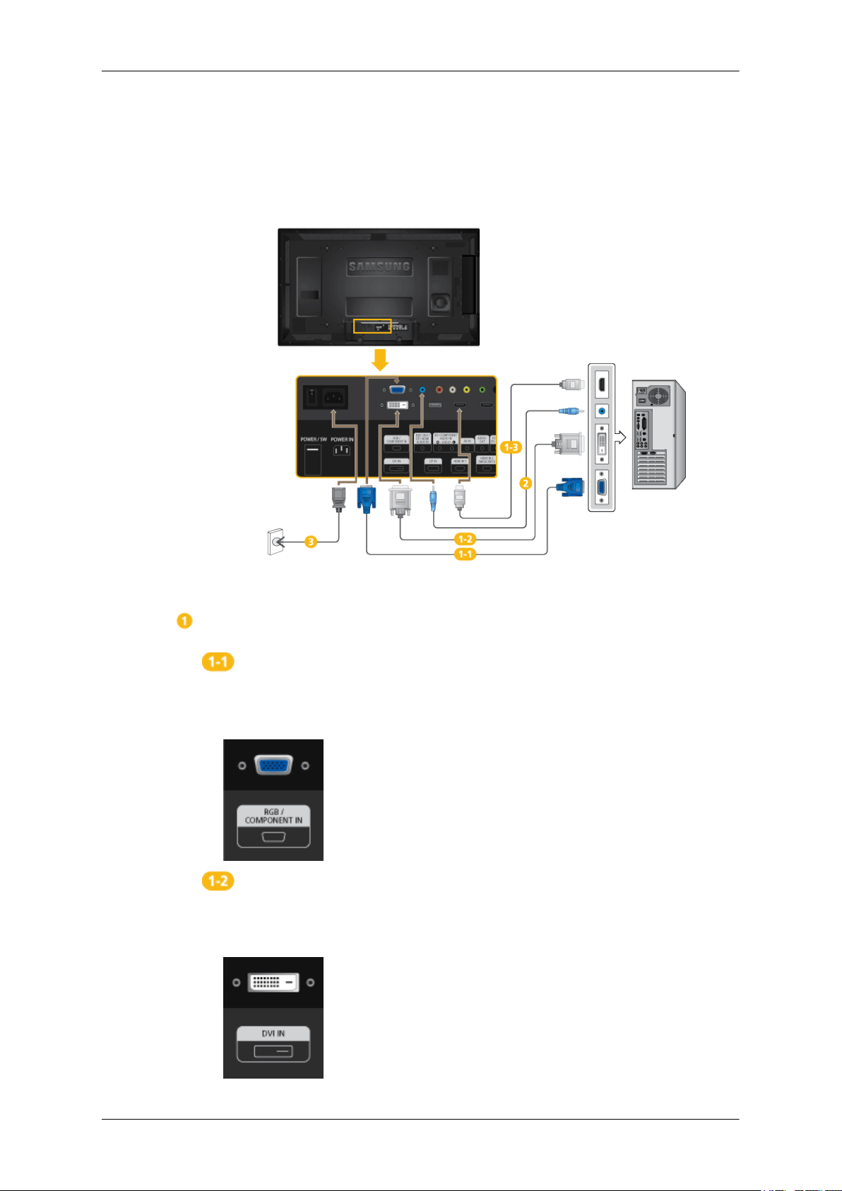
There are several ways to connect the computer to the monitor. Choose one from
the following options.
Using the D-sub (Analog) connector on the video card.
• Connect the
of your LCD Display and the 15 pin D-sub Port on the computer.
Using the DVI (Digital) connector on the video card.
• Connect
and the DVI port on the computer.
D-sub to the 15-pin, [RGB/COMPONENT IN] port on the back
the
DVI Cable to the [DVI IN] port on the back of your LCD Display

Connections
Using the D-sub (Digital) connector on the video card.
• Connect the [
HDMI port on the PC using the HDMI cable.
Note
Select HDMI2 or HDMI1
HDMI cable.
To obtain normal picture and audio from the PC, HDMI2 or HDMI1 must be
selected before PC is selected in Edit Name.
To enable audio when DVI Device is selected, be sure to establish the connection
using step (
HDMI IN 1] / [HDMI IN 2] port on the LCD Display to the
as an input source when connected to the PC via an
).
Connect the Audio cable for your LCD Display to the AUDIO port on the back
of the LCD Display.
Connect the power cord for your LCD Display to the POWER port on the back of
the LCD Display. Turn on the power switch.
Note
Contact a local SAMSUNG Electronics Service Center to buy optional items.
Connecting to Other devices
Note
• AV input
connected to the LCD Display. For detailed information on connecting AV input devices, refer to
the contents under Adjusting Your LCD Display.
• The LCD Display 's configuration at the back may vary slightly depending on the LCD Display
model.
devices such as DVD players, VCRs or camcorders as well as your computer can be

Connecting AV Devices
1. Connect an audio cable to [AV/COMPONENT AUDIO IN [L-AUDIO-R]] on the
product and the audio port on an external device such as a VCR or DVD player.
Connections
2. Connect a video cable to [AV IN]
external device.
3. Then, start the DVD, VCR or Camcorders with a DVD disc or tape inserted.
4. Press SOURCE on the product or remote control and select AV.
Connecting to a Camcorder
the product and the video output port on the
on
1. Locate the AV output jacks on the camcorder. They are usually found on the side
or back of the camcorder. Connect a video cable between the VIDEO OUTPUT
jack on the camcorder and the [AV IN] on the LCD Display .
2. Connect a set of audio cables between the AUDIO OUTPUT jacks on the camcorder and the [AV /COMPONENT AUDIO IN [L-AUDIO-R]] on the LCD
Display .

3. Press SOURCE on the product or remote control and select "AV".
4. Then, start the Camcorders with a tape inserted.
Note
The audio-video cables shown here are usually included with a Camcorder.
(If not, check your local electronics store.)
If your camcorder is stereo, you need to connect a set of two cables.
Connecting Using a HDMI Cable
Connections
1. Connect an HDMI cable to [HDMI IN 2 (MAGICINFO)] or [HDMI IN 1] on the
product and the HDMI output port on a digital device.
2. Press SOURCE on the product or remote control and select "HDMI1 / HDMI2"
Note
In HDMI mode, only PCM format audio is supported.

Connections
Connecting Using a DVI to HDMI Cable
Connect a DVI-HDMI cable to [HDMI IN
the DVI output port on the digital device.
Connect the red and white jacks of an RCA to stereo (for PC) cable to the same
colored audio
posite jack to the [RGB/DVI/DP/HDMI AUDIO IN] terminal of the LCD Display.
3. Press SOURCE on the product or remote control and select "HDMI1 / HDMI2"
Connecting a DVD Player
2 (MAGICINFO)] or [HDMI IN 1] and
output terminals of the digital output device, and connect the op-
Connect a RGB to Component cable between the [RGB/COMPONENT IN] port
on the LCD Display and the PR, Y, PB jacks on the DVD player.
Connect a set of audio cables between the [AV/COMPONENT AUDIO
AUDIO-R]] on the LCD Display and the AUDIO OUT jacks on the DVD player.
IN [L-
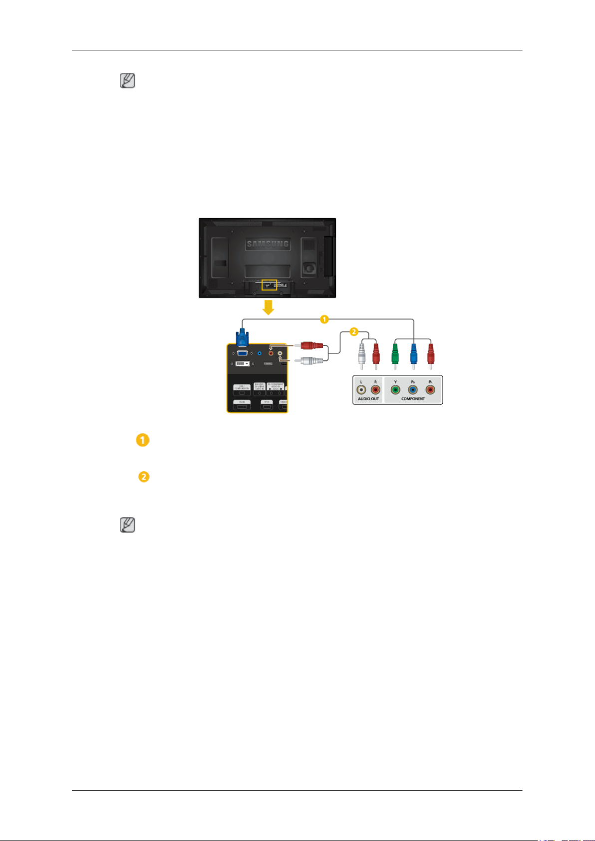
Note
Connections
• Press SOURCE
• Then, start the DVD Player with a DVD disc inserted.
• A RGB to component cable is optional.
• For an explanation of Component video, consult your DVD manual.
on the product or remote control and select "Component".
Connecting a DTV Set Top (Cable/Satellite) Box
Connect a set of audio cables between the [AV/COMPONENT AUDIO IN
• Press SOURCE
• For an explanation of Component video, see your Set Top Box owner's manual.
Connect a RGB to Component cable between the [RGB/COMPONENT IN] port
on the LCD Display and the PR, Y, PB jacks on the Set Top Box.
AUDIO-R]] on the LCD Display and the AUDIO OUT jacks on the Set Top Box.
Note
on the product or remote control and select "Component".
[L-

Connecting to an Audio System
1. Connect a set of audio cables between the AUX L, R jacks on the AUDIO SYSTEM and [AUDIO OUT] on LCD Display.
Connections
Connecting a Network Box (sold separately)
Note
• Network boxes are sold separately.
For more information on how to purchase and install a network box, contact Samsung Electronics.
•
Connecting the Power
Connect the [POWER] terminal of the product and the [POWER] terminal of the
installed network box using a power extension cable.
Connect the power cord to [POWER] on the network box and mains socket.
Turn on the power switch.

Connecting to MAGICINFO OUT
Connect the [MAGICINFO OUT] terminal of the network box and the [HDMI IN 2 (MAGICINFO)]
terminal of the monitor using the HDMI cable.
Connections
Connecting a LAN Cable
Connect the LAN cable between the [LAN] port on the product and the [LAN] port on your PC.

Connecting a USB devices
You can connect USB devices such as a mouse or keyboard.
Connections

Using the Software
Monitor Driver
Note
When prompted by the operating system for the monitor driver, insert the CD-ROM
included with
system to another. Follow the directions appropriate for the operating system you
have.
Prepare a blank disk and download the driver Program file at the Internet web site
shown here.
Internet web site :
http://www.samsung.com/
Installing the Monitor Driver (Automatic)
1. Insert CD into the CD-ROM drive.
Click "Windows".
2.
3. Choose your monitor model in the model list, then click the "OK" button.
this monitor. Driver installation is slightly different from one operating
4. If you can see following message window, then click the "Continue Anyway" button. Then click
"OK" button (Microsoft® Windows® XP/2000 Operating System).

Using the Software
Note
This monitor driver is certified by Microsoft, and installing it will not damage your system.
The certified driver will be posted on Samsung Monitor homepage.
http://www.samsung.com/
Installing the Monitor Driver (Manual)
Microsoft® Windows Vista™‚ Operating System
Insert your Manual CD into your CD-ROM drive.
1.
2.
Click (Start) and "Control Panel". Then, double-click on "Appearance and Personalization".
3. Click "Personalization" and then "Display Settings".
4. Click "Advanced Settings...".
5. Click "Properties" in the "Monitor" tab. If the "Properties" button is deactivated, it means the
configuration for your monitor is completed. The monitor can be used as is.
If
the message "Windows needs..." is displayed, as shown in the figure below, click "Continue".

Note
Using the Software
This monitor
The certified driver will be posted on Samsung Monitor homepage.
6. Click "Update Driver..." in the "Driver" tab.
7. Check the "Browse my computer for driver software" checkbox and click "Let me pick from a
list of device drivers on my computer".
driver is under certifying MS logo, and this installation will not damage your system.
8. Click "Have Disk...” and select the folder (for example, D:\Drive) where the driver setup file is
located, and click "OK".

Using the Software
9. Select the model that matches your monitor from the list of monitor models on the screen, and
click "Next".
10.
Click "Close" → "Close" → "OK" → "OK" on the following screens displayed in sequence.
Microsoft® Windows® XP Operating System

Using the Software
1. Insert CD into the CD-ROM drive.
2.
Click "Start" → "Control Panel", then click the "Appearance and Themes" icon.
3. Click "Display" icon and choose the "Settings" tab then click "Advanced...".
4. Click the "Properties" button on the "Monitor" tab and select "Driver" tab.
5. Click "Update Driver..." and select "Install from a list or..." then click "Next" button.
6. Select "Don't search, I will...", then click "Next" and then click "Have disk".

Using the Software
7. Click the "Browse" button then choose A:(D:\Driver) and choose your monitor model in the model
list and click the "Next" button.
8. If you can see the following message window, then click the "Continue Anyway" button. Then
click "OK" button.
Note
This monitor driver is certified by Microsoft, and this installation will not damage your system.
The certified driver will be posted on Samsung Monitor homepage.
http://www.samsung.com/
9. Click the "Close" button, then click the "OK" button continually.

Using the Software
10. Monitor driver installation is completed.
Microsoft® Windows® 2000 Operating System
When you can see "Digital Signature Not Found" on your monitor, follow these steps.
1. Choose "OK" button on the "Insert disk" window.
2.
Click the "Browse" button on the "File Needed" window.
3. Choose A:(D:\Driver), then click the "Open" button and then click "OK" button.
How to install
1. Click "Start", "Setting", "Control Panel".
2. Double click the "Display" icon.
3. Select the "Settings" tab and click "Advanced Properties" button.
4. Choose "Monitor".
Case1 : If the "Properties" button is inactive, it means your monitor is properly configured. Please
stop installation
Case2 : If the "Properties" button is active, click the "Properties" button, then follow the next
steps.
5. Click "Driver" and then click on "Update Driver...", then click on the "Next" button.
6. Choose "Display a list of the known drivers for this device so that I can choose a specific driver",
then click "Next" and then click "Have disk".
7. Click the "Browse" button, then choose A:(D:\Driver).
8. Click the "Open" button, then click "OK" button.
9. Choose your monitor model and click the "Next" button. Then click "Next" button.
10. Click the "Finish" button, then the "Close" button.
If you can see the "Digital Signature Not Found" window, then click the "Yes" button. Then click
the "Finish" button and the "Close" button.
Microsoft® Windows® Millennium Operating System
1. Click "Start", "Setting", "Control Panel".
2. Double click the "Display" icon.
3. Select the "Settings" tab and click "Advanced Properties" button.

Using the Software
4. Select the "Monitor" tab.
5. Click the "Change" button in the "Monitor Type" area.
6.
Choose "Specify the location of the driver".
7. Choose "Display a list of all the driver in a specific location...", then click "Next" button.
8. Click the "Have Disk" button.
9. Specify A:\(D:\driver), then click "OK" button.
10. Select "Show all devices" and choose the monitor that corresponds to the one you connected to
your computer and click "OK".
11. Continue choosing "Close" button and "OK" button until you close the Display Properties dialogue box.
Microsoft® Windows® NT Operating System
1. Click "Start", "Settings", "Control Panel", and then double-click "Display" icon.
2. In Display Registration Information window, click Settings Tab and then click "All Display
Modes".
3. Select a mode that you wish to use (Resolution, Number of Colors and Vertical frequency) and
then click "OK".
4. Click "Apply" button if you see the screen working normally after clicking "Test". If the screen
is not normal, change to a different mode (lower mode of resolution, Colors or frequency).
Note
If there
referring to the Preset Timing Modes in the user guide.
Linux Operating System
To execute X-Window, you need to make the X86Config file, which is a type of system setting file.
1. Press "Enter" at the first and the second screen after executing the X86Config file.
2. The third screen is for setting your mouse.
3. Set a mouse for your computer.
4. The next screen is for selecting a keyboard.
5. Set a Keyboard for your computer.
6. The next screen is for setting your monitor.
is no Mode at All Display Modes, select the level of resolution and vertical frequency by
7. First of all, set a horizontal frequency for your monitor. (You can enter the frequency directly.)
8. Set a vertical frequency for your monitor. (You can enter the frequency directly.)
9. Enter the model name of your monitor. This information will not affect the actual execution of
X-Window.
10. You have finished setting up your monitor. Execute X-Window after setting other requested
hardware.

MDC (Multi-Display Control)
Installation
1.
Insert the installation CD into the CD-ROM drive.
Click the MDC System installation Program.
2.
Note
If the
screen for installing the software does not appear, install it using the MDC System execution
file in the MDC folder of the CD-ROM.
3. If the installation wizard screen does appear, click "Next."
4. The "License Agreement" screen will appear. Click "Yes."
Using the Software
5. The "Customer Information" window will appear. Register the user information and click "Yes."
6. The "Choose Destination Location" window will appear. Specify the file location to install to and
click "Next."
Note
If the file location is not specified, the Program will be installed in the default file location.
7. The "Start Copying Files" window will appear. Confirm the file location and click "Next."
8.
The installation progress screen will appear.
9. The "InstallShield Wizard Complete" screen will appear. Click "Finish."
Note
Select " Launch MDC System" and click "Finish." The MDC Program will immediately be run.
10. If the installation is successfully completed, the quick MDC System execution icon will appear
on the desktop.
execution icon may not appear depending on specification of computer system or
MDC
monitor. If that happens, press F5 Key.
Installation Problems
The installation
environment.
of MDC can be affected by such factors as the video card, motherboard and the network

Uninstall
Using the Software
The MDC
Windows® Control Panel.
Perform the following steps remove MDC.
Select "Setting/Control Panel" on the "Start" menu and then double-click "Add/Delete a Program".
Select MDC System from the list and then click the "Add/Delete" button.
Using Serial MDC
Using Ethernet MDC
Program can be removed only by using the "Add or Remove Programs" option of the
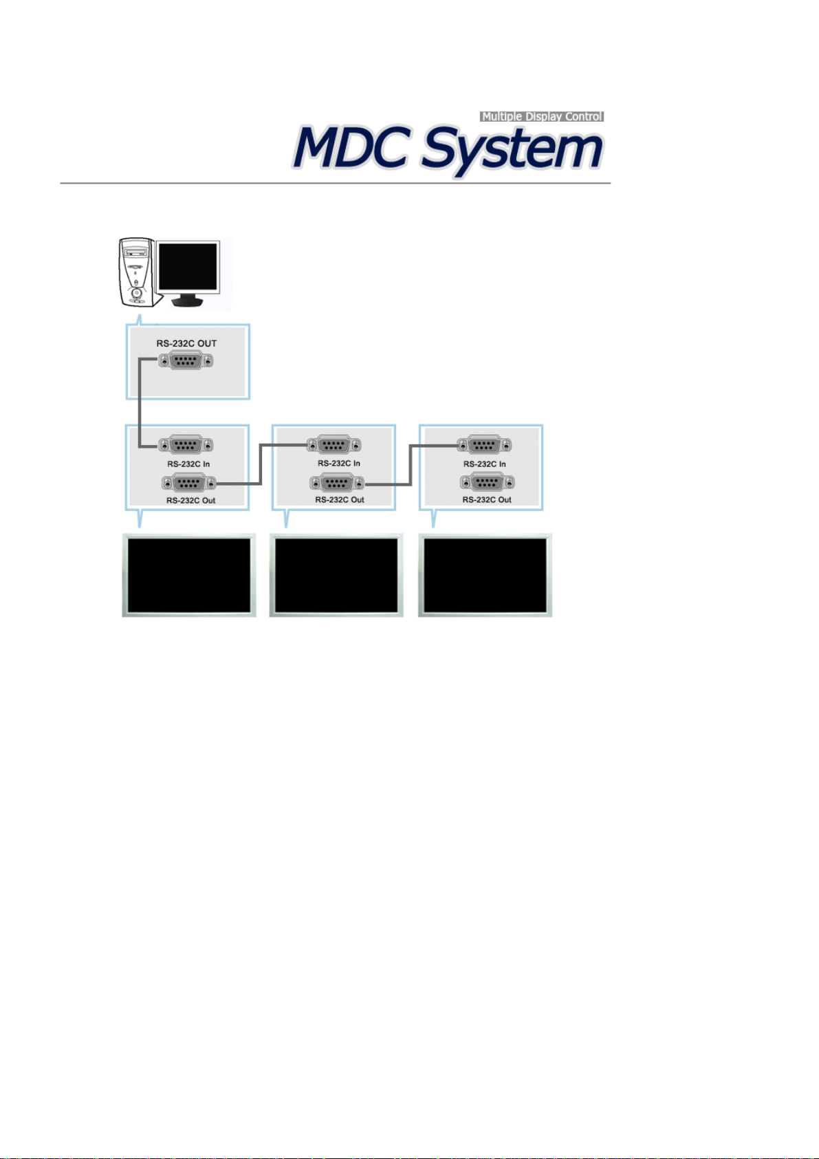
Introduction
Serial MDC
A Multiple Display Control (MDC) is an application allowing various displays to be easily and simultaneously
operated on a PC. RS-232C, a standard of serial communication, is used for the communication between a PC and
a display. Therefore, a serial cable should be connected between the serial port on a PC and the serial port on a
display.
Main Screen
Click Start > Program > Samsung > MDC System to start the program.
Select a set to see the volume of the selected set within the slider.
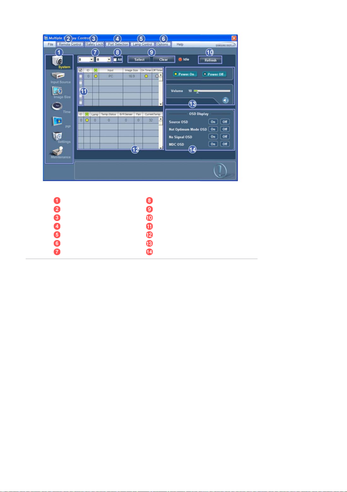
Main Icons All
Remote control Selection Buttons
Safety Lock Refresh
Port Selection Display Selection
Lamp Control Info Grid
Option... Control Tools
Dropdown Selectors OSD Display
1. Use the main icons to switch into each screen.
2. Allows you to enable or disable the remote control signal receiving function of the display unit.
3. Set the Safety Lock function.
When setting the Lock function, you can only operate power and lock buttons on the remote control and set.
4. The setting for the PC Serial Port can change. The original value is COM1.
5. Selects a Lamp adjustment mode.
6. Adjusts the number of LFD IDs and the frequency of search repeats.
7. Defines the range of LFD IDs to display. You can select or deselect t he displayed IDs using the Select or Clear
button.
8. All of the monitors can be selected or deselected.
9. Selects (Select) or deselects (Clear) LFD IDs displayed by configuring 7 and 8.
10. This searches for monitors. The maximum number is indicated in the Max LFD Id field.
11. Select a display from Display Selection.
12. Use Grid to view brief information on selected display.
13. Use Control Tools to control displays.
14. Switches the OSD function On/Off.
- May not be supported depending on the product.
<Note> The remote control Enable/Disable function operates whether or not the power is On/Off, and this
applies to all displays connected to the MDC. However, regardless of the status at the time the MDC is
shut down, the remote control signal receiving function of all displays is initialized to Enable when the
MDC is closed.
Port Selection
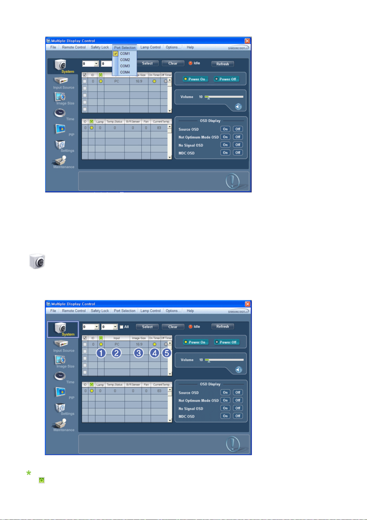
1. The Multiple Display Control is originally set to COM1.
2. If any port other than COM1 is used, COM1 through COM4 can be selected in the Port Selection Menu.
3. If the exact port name that is connected to the LCD Display using a serial cable is not selected, communication will
be unavailable.
4. The selected port is stored in the program and used for the next program as well.
System
1. Click System in the main menu to open the system adjustment screen.
Info Grid shows some basic information necessary to System.
1) (Power Status)
2) Input

3) Image Size
4) On Timer
5) Off Timer
2. Selects displays you want to adjust using the Select button or checkboxes.
System allows controlling some of the functions of the selected display.
1) Power On/Off
- Turns the power of the selected display On/Off.
2) Volume
- Controls the volume level of the selected display.
It receives the volume value of the selected display from the sets and displays it in the slider.
(If you deselect a single display or all displays, the default value 10 will be restored.)
3)
(Mute On/Off)
- Turns on/off the Mute function of the selected display.
When selecting one set at a time, turn on the Mute function for the selected set.
The Mute function is disabled automatically when you adjust the volume level.
(The values return to the default settings when you undo the selections or choose "Select All".)
The Volume Control and Mute features are available only for the displays whose power status is ON.
3. Selects whether to display the menu screen using the OSD Display menu.

1) Source OSD
- Sets whether the Source OSD will be displayed to indicate when the Source is changed.
2) Not Optimum Mode OSD
- Sets whether the Optimum Mode OSD will be displayed to indicate if the current mode is not supported.
3) No Signal OSD
- Sets whether the No Signal OSD will be displayed to indicate when there is no signal.
4) MDC OSD
- Sets whether the MDC OSD will be displayed to indicate when the settings are changed using the MDC.
Input Source
1. Click Input Source of the main icons and the Input Source control screen appears.
Selects displays you want to adjust using the Select button or checkboxes.
• TV Mode
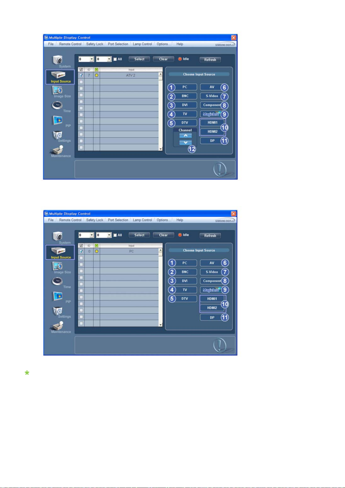
• PC Mode
Info Grid shows some basic information necessary to Input Source Control.
1) PC
- Changes the Input Source of the selected display to PC.
2) BNC
- Changes the Input Source of the selected display to BNC.
3) DVI
- Changes the Input Source of the selected display to DVI.
4) TV
- Changes the Input Source of the selected display to TV.
5) DTV
- Changes the Input Source of the selected display to DTV.
6) AV
- Changes the Input Source of the selected display to AV.
7) S-Video
- Changes the Input Source of the selected display to S-Video.
8) Component
- Changes the Input Source of the selected display to Component.
9) MagicInfo
- The Input source of MagicInfo works only on MagicInfo model.
10) HDMI1/HDMI2
- Changes the Input Source of the selected display to HDMI.
11) DP
- Switches the input source for the selected Display to DP.
12) Channel
- Channel arrow appears when the Input Source is TV.
HDMI2 may not be supported depending on the product.
DP may not be supported depending on the product.
TV Source can be selected only in products with TV and controlling channels is allowed only when
Input Source is TV.
The Input Source Control feature is available only for the displays whose power status is ON.
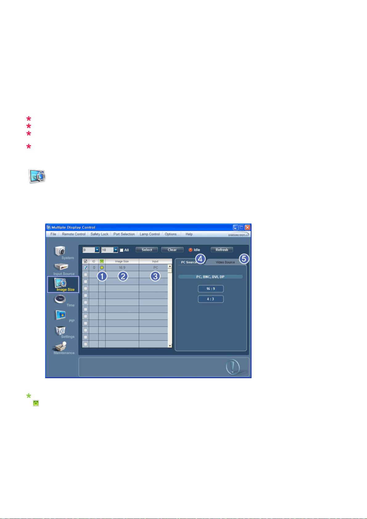
Image Size
PC, BNC, DVI, DP
1. Click Image Size of the main icons and the Image Size control screen appears.
Info Grid shows some basic information necessary to Image Size Control.
1)
( Power Status)
- Shows the power status of the current display.
2) Image Size
- Shows the current Image Size of the display in use.
3) Input
- Info Grid displays only the displays whose Input Source is PC, BNC, DVI and DP.
4) PC Source
- Click Image Size in the main menu to display the PC, BNC, DVI and DP tabs.
- The Image Size Control button controls Image Size available for PC, BNC, DVI and DP.
5) Video Source
- Using the Image Size adjustment button, you can adjust the Image Size to a value available in the PC, BNC, DVI
and DP.

DP may not be supported depending on the product.
The Input source of MagicInfo works only on MagicInfo model.
The Input source of TV works only on TV model.
Image Size Control is available only for the displays for which power status is ON.
Image Size
TV, AV, S-Video, Component, DVI(HDCP), HDMI1, HDMI2, DTV.
1. Click Image Size of the main icons and the Image Size control screen appears.
Info Grid shows some basic information necessary to Image Size Control.
1) To adjust Image Size in TV, AV, S-Video, Component, HDMI1, HDMI2 or DTV mode, click the Video Source tab.
Select the display you want to adjust by using the Select button or by checking the checkbox.
2) Info Grid displays only the display havi ng TV, AV, S-Video, Component, HDMI1, HDMI2 or DTV as input source.
3) Switch Image Size of the selected display randomly.
4) The screen modes can only be adjusted when a TV (PAL only) is connected and the Image Size item is set to Auto
Wide.
HDMI2 may not be supported depending on the product.
Custom may not be supported dependin g on t h e product.
Auto Wide, Zoom1 and Zoom2 are not available for selection when the input signal type for Component
and DVI (HDCP) is 720p or 1080i.
(The Auto Wide mode is available only for TV, AV, and S-Video.)
The Input source of MagicInfo works only on MagicInfo model.
The Input source of TV works only on TV model.
The Image Size Control feature is available only for the displays whose power status is ON.
Time
1. Click Time of the main icons and the Time Control screen appears.

Info Grid shows some basic information necessary to Time Control.
1) Set clock
- Set the current time for the selected display (PC Time).
- To change the current time, first change the PC Time.
2) Timer
- Sets up Timer1, Timer2, Timer3 and Holiday Management.
3) Shows whether Timer is activated.
The Input source of MagicInfo works only on MagicInfo model.
The Input source of TV works only on TV model.
Time Control is available only for the displays for which the power status is ON.
Time
Setting up Timer and Holiday Management
1. 1. Setting up Timer1, Timer2 and Timer3
1) On Time
- Sets the time in hours, in minutes and as AM/PM for turning the selected monitor on.
2) Off Time
- Sets the time in hours, in minutes and as AM/PM for turning the selected monitor off.
3)
Volume

- Selects the volume when the selected monitor is turned on.
4) Source
- Selects the external input source that will be displayed when the selected monitor is turned on.
5) Holiday
- Applies the Holiday Management function to the Timer.
6) Repeat
- Available selections include Once, EveryDay, Mon~Fri, Mon~Sat, Sat~Sun, and Manual.
z Once : The Timer goes off only once.
z EveryDay : EveryDay: The Timer repeats daily.
z Mon~Fri : The Timer repeats from Monday through Friday.
z Mon~Sat : The Timer repeats from Monday through Saturday.
z Sat~Sun : Sat~Sun: The Timer goes off on Saturday and Sunday.
z Manual : Select a day of the week you want the Timer to go off.
2. Setting Holiday Management
The Holiday Management function specifies the dates in which the monitor will not be turned on or off by the Timer.
1) Specifies the date.
2) Delete All
- Deletes all of the holidays.
3) Add
- Adds the specified date.
4)
- Deletes the schedule in the selected line.
The Holiday Management function can be turned on or off in the Timer setup menu.
The Input source of MagicInfo works only on MagicInfo model.
The Input source of TV works only on TV model.
Time Control is available only for the displays for which the power status is ON.
Only enabled for a TV when Source is set to TV in On Time mode.
Only enabled for a model with MagicInfo installed when Source is set to MagicInfo in On Time mode.
PIP
PIP Size
1. Click PIP of the main icons and the PIP control screen appears.
Selects displays you want to adjust using the Select button or checkboxes.

Info Grid shows some basic information necessary to PIP Size Control.
1) PIP Size
- Shows the current PIP Size of the display in use.
2) OFF
- Turns off the PIP of the selected display.
3) Large
- Turns on the PIP of the selected display and changes the size to Large.
4) Small
- Turns on the PIP of the selected display and changes the size to Small.
5) Double 1
- Turns on the PIP of the selected display and changes the size to Double 1.
6) Double 2
- Turns on the PIP of the selected display and changes the size to Double 2.
7) Double 3 (Picture By Picture)
- Turns on the PBP of the selected display and changes the size to Double 3.
The Input source of MagicInfo works only on MagicInfo model.
The Input source of TV works only on TV model.
PIP Size can be controlled with turning on the LCD Display power.
PIP
PIP Source
1. Click PIP of the main icons and the PIP control screen appears.

Info Grid shows some basic information necessary to PIP Source Control.
1) PIP Source
- PIP Source can be controlled with turning on the LCD Display power.
2) PC
- Changes the source of the PIP of the selected display to PC.
3) BNC
- Changes the source of the PIP of the selected display to BNC.
4) DVI
- Changes the source of the PIP of the selected display to DVI.
5) TV
- Changes the source of the PIP of the selected display to TV.
6) DTV
- Changes the source of the PIP of the selected display to DTV.
7) AV
- Changes the source of the PIP of the selected display to AV.
8) S-Video
- Changes the source of the PIP of the selected display to S-Video.
9) Component
- Changes the source of the PIP of the selected display to Component.
10) HDMI1/HDMI2
- Changes the source of the PIP of the selected display to HDMI.
11) DP
- Switches the PIP Source of the selected Display to DP.
HDMI2 may not be supported depending on the product.
DP may not be supported depending on the product.
Some of the PIP Sources may not be available for selection, depending on the input source type of the
Main Screen.
The Input source of MagicInfo works only on MagicInfo model.
The PIP Control feature is available only for the displays whose power status is ON and the PIP
function is set to ON.
Settings
Picture
1. Click Settings of the main icons and the Settings Control screen appears.

Basic information required to adjust the Picture is displayed in the main menu. Settings for the selected monitor will
be displayed if one of the connected monitors is selected, and the default settings will be displayed if all monitors
are selected by clicking All and Select. If a value is changed in this screen, the current mode will automatically
switch to custom mode.
1) Picture
- Available only for TV, AV, S-Video, Component, HDMI1, HDMI2, DTV.
2) Contrast
- Adjusts Contrast of the selected display.
3) Brightness
- Adjusts Brightness of the selected display.
4) Sharpness
- Adjusts Sharpness of the selected display.
5) Color
- Adjusts Color of the selected display.
6) Tint
- Adjusts Tint of the selected display.
- Available only for NT.
7) Color Tone
- Adjusts the Color Tone for the selected display.
8) Color Temp
- Adjusts the Color Temp for the selected display.
9) Brightness Sensor
- Adjusts the Brightness Sensor for the selected display.
10) Dynamic Contrast
- Adjusts the Dynamic Contrast for the selected display.
HDMI2 may not be supported depending on the product.
Brightness Sensor may not be supported depending on the product.
The Input source of MagicInfo works only on MagicInfo model.
Color Temp is only enabled if the Color Tone is set to Off.
The Input source of TV works only on TV model.
This feature is available only for the displays whose power status is ON and if no selection is made, the
factory default is displayed.
Settings
Picture PC

1. Click Settings of the main icons and the Settings Control screen appears.
Basic information required to adjust settings is displayed. Settings for the corresponding SET will be imported and
displayed on the slider if a display ID is selected, and the defau lt settings will be displayed if all display IDs are
selected by clicking All and Select. If a value is changed in this screen, the current mode will automatically switch to
custom mode.
1) Picture PC
- Available only for PC, BNC, DVI and DP.
2) Contrast
- Adjusts Contrast of the selected display.
3) Brightness
- Adjusts Brightness for the selected display.
4) Red
- Adjusts red Color of the selected display.
- Available only for NT.
5) Green
- Adjusts green Color of the selected display.
- Available only for NT.
6) Blue
- Adjusts blue Color of the selected display.
- Available only for NT.
7) Color Tone
- Adjusts the Color Tone for the selected display.
8) Color Temp
- Adjusts the Color Temp for the selected display.
9) Brightness Sensor
- Adjusts the Brightness Sensor for the selected display.
10) Dynamic Contrast
- Adjusts the Dynamic Contrast for the selected display.
DP may not be supported depending on the product.
Brightness Sensor may not be supported depending on the product.
The Input source of MagicInfo works only on MagicInfo model.
The Input source of TV works only on TV model.
Color Temp is only enabled if the Color Tone is set to Off.
This feature is available only for the displays whose power status is ON and if no selection is made, the
factory default is displayed.

Settings
Audio
1. Click Settings of the main icons and the Settings Control screen appears.
Basic information required to adjust Audio is displayed in the display window. Settings for the corresponding SET will
be imported and displayed on the slider if a display ID is selected, and the default settings will be displayed if all
display IDs are selected by clicking All and Select. If a value is changed in this screen, the current mode will
automatically switch to custom mode.
1) Audio
- Controls audio settings for all input sources.
2) Bass
- Adjusts Bass of the selected display.
3) Treble
- Adjusts Treble of the selected display.
4) Balance
- Adjusts Balance of the selected display.
5) SRS TS XT
- SRS TS XT Sound ON/OFF of the selected display.
6) Sound Select
- Select either Main or Sub when PIP is On.
The Input source of MagicInfo works only on MagicInfo model.
The Input source of TV works only on TV model.
This feature is available only for the displays whose power status is ON and if no selection is made, the
factory default is displayed.
Settings
Image Lock
1. Click Settings of the main icons and the Settings Control screen appears.

Info Grid shows some basic information necessary to Settings Control.
1) Image Lock
- Available only for PC, BNC.
2) Coarse
- Adjusts Coarse of the selected display.
3) Fine
- Adjusts Fine of the selected display.
4) Position
- Adjusts Position of the selected display.
5) Auto Adjustment
- Self-Adjust to the incoming PC signal.
The Input source of MagicInfo works only on MagicInfo model.
The Input source of TV works only on TV model.
Settings Control is available only for the displays for which the power status is ON.
Maintenance
Lamp Control
1. Click on the "Maintenance" icon in the Main Icon column to display the Maintenance screen.

An "Info Grid" showing several basic data items appears.
1) Maintenance
- Allows the Maintenance Control function for all input sources.
2) Lamp Control
- Automatically adjusts the backlight of the selected display at a specified time.
The Manual Lamp Control automatically turns off if you adjust using the Auto Lamp Control.
- Allows you to adjust the backlight of the selected display regardless of the time.
The Auto Lamp Control automatically turns off if you adjust using the Manual Lamp Control.
3) Ambient Light
- Detects the ambient light intensity at the designated monitor and automatically adjusts the picture brightness.
- You can specify a Reference value and designate a monitor that will automatically determine Lamp Value (the light
intensity from the lamp), based on the ambient light intensity.
Ambient Light is only supported for models that have a brightness sensor and is only enabled when
Ambient Brightness Mode is selected in the Lamp Control menu.
Auto Lamp Control and Manual Lamp Control are only enabled when User Control Mode is selected in
the Lamp Control menu.
The Maintenance Control feature is available only for the displays whose power status is ON.
The Input source of MagicInfo works only on MagicInfo model.
The Input source of TV works only on TV model.
Maintenance
Scroll
1. Click on the "Maintenance" icon in the Main Icon column to display the Maintenance screen.

1) Scroll
- This function is used to remove the afterimages that occur when a still screen is displayed on the sel ected
display
for a long time.
2) Pixel Shift
- This allows the screen to be moved finely at the specified time interval.
3) Safety Screen
- The Safety Screen function is used to prevent afterimages from occurring when a still screen is displayed on the
monitor for a long time. The Interval item is used to set the repetition cycle in hour units and the Time item is
used to set the time when the Safety Screen function must be performed.
The Type item can be set to Scroll, Pixel, Bar, Eraser, All White, or Pattern.
4) Safety Screen2
- This function is used to prevent afterimages from occurring. There are five (5) types that you can select and
control with this function.
For the Scroll type, the Time item can be set to 1, 2, 3, 4 or 5. For the Bar and Eraser types, it can be set
to 10, 20, 30, 40 or 50. For the All White and Pattern type, it can be set to 1, 5, 10, 20 or 30.
The Input source of MagicInfo works only on MagicInfo model.
The Input source of TV works only on TV model.
The Maintenance Control feature is available only for the displays whose power status is ON.
Maintenance
Video Wall
1. Click on the "Maintenance" icon in the Main Icon column to display the Maintenance screen.
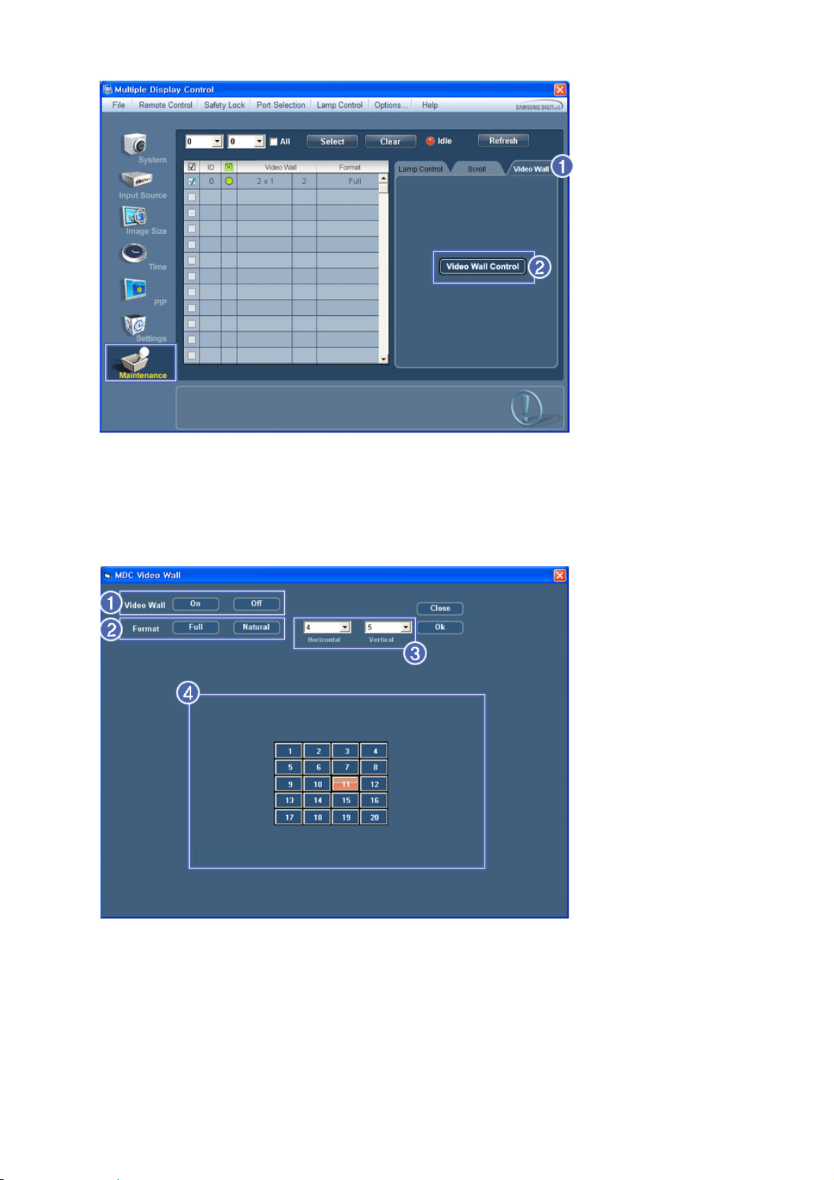
1) Video Wall
- A Video Wall is a set of video screens that are connected together, so that each screen shows a part of the whole
picture or so that the same picture is repeated on each screen.
2) Video Wall Control
- Video Wall properties can be configured.
1) On / Off
- Turns on/off the Video Wall function of the selected display.
2)
Format
- The format can be selected to see a divided screen.
z Full

z Natural
3) Video Wall (Screen divider)
- The screen can be divided into.
You can select a number of screens with a different layout when dividing.
z Select a mode from Screen divider.
z Select a display from Display Selection.
z The place will be set up by pressing a number in the selected mode.
z The maximum number of monitors that can be arranged: Horizontal X Vertical = 100
z Up to 15 monitors can be arranged in a row. The maximum value for Horizontal is 6 if Vertical is set to 15 while
the maximum value for Vertical is 6 if Horizontal is set to 15.
4) Viewing Screen Splits
- You can view and change the layout of screens using the Screen Divider settings.
The range of the Screen Divider setting may differ depending on the model.
You may not operate this function in MagicInfo.
The Input source of TV works only on TV model.
The Maintenance Control function is available only for the displays where the power status is ON.
Troubleshooting
1. The display you wish to control does not appear on the System Info Grid
- Check the connection of RS232C. (Check if it is properly connected to the Com1 port
- Check the displays to see if any of the other displays connected have the same ID. If more than one displays have
the same ID, those displays are not properly detected by the program due to data conflict.
- For monitors that support a Set ID between 0 to 99, you have to set the Set ID to a value between 0 and 99.
Note : Check if the Set ID of the monitor is a value between 0 and 99 (set the value using the Display menu).
2. The display you wish to control does not appear on the other Control Info Grids
- Check to see if the display power is ON. (You can check this in System Info Grid)
- Check if you can change the input source of the display.
3. The dialogue box appears repeatedly.
- Check to see if the display you wish to control is selected.
4. Both On Timer and Off Timer have been set but different time is showing.
- Apply current time to synchronize the display clocks.
5. The remote may not function properly when you turn off the remote Function, disconnect the RS-232C cable, or exit
the program in an Irregular manner. Rerun the program and turn the remote function again to Restore normal
functions.
<Note> This program may malfunction due to problems in communication circuits or interference from electronic
appliances nearby.

Settings Value Display In Multiple Display Mode
When there are more than one displays connected, the settings values are displayed as follows.
1. No selection: Displays the Factory Default Value.
2. Selected one display: Fetches and displays the settings value for the selected display.
3. Selected one display (ID1) and add another display (ID3): The program, which was displaying the settings value of
ID 1, fetches and displays the value of ID3.
4. If all sets are selected at the same time by clicking All and Select, the default value will be restored.
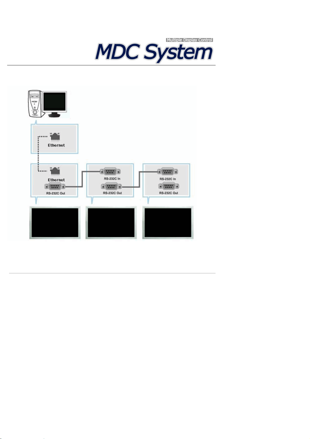
Introduction
Ehternet MDC
Unlike the previous method which used the serial data communication specifications RS-232C, an Ethernet
function has been added.
Connect the first display device and the PC by entering the IP address. To connect to another display device,
use an RS-232C serial cable. Refer to the figure above.
Main Screen
Click Start > Program > Samsung > MDC System to start the program.
Select a set to see the volume of the selected set within the slider.
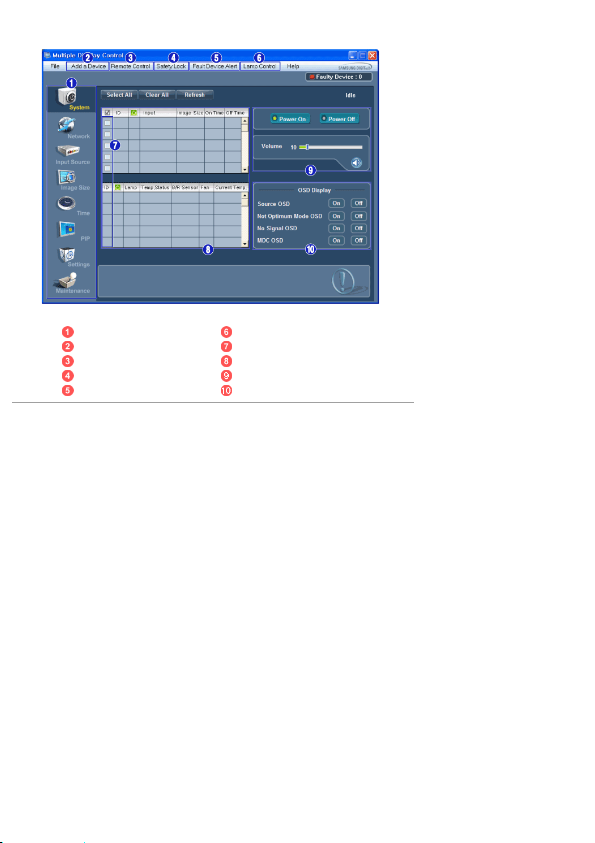
Main Icons Lamp Control
Add a Device Display Selection
Remote Control All
Safety Lock Control Tools
Fault Device Alert OSD Display
1. Use the main icons to switch into each screen.
2. You can add a device by entering the IP address configured on the monitor.
3. Allows you to enable or disable the remote control signal receiving function of the display unit.
4. Set the Safety Lock function.
5. When connecting to the monitor fails, it turns the function that transfers the result through an email on or off.
6. Selects a Lamp adjustment mode.
7. Select a display from Display Selection.
8. All of the monitors can be selected or deselected.
9. Use Control Tools to control displays.
10. Switches the OSD function On/Off.
When setting the Lock function, you can only operate power and lock buttons on the remote control and set.
- May not be supported depending on the product.
<Note> The remote control Enable/Disable function operates whether or not the power is On/Off, and this
applies to all displays connected to the MDC. However, regardless of the status at the time the
MDC is shut down, the remote control signal receiving function of all displays is initialized to
Enable when the MDC is closed.
Add a Device

1. Enter the IP address of the monitor to be connected and press the Add button to add the IP address. If you
click the OK button, adding the monitor is completed.
System
1. Click System in the main menu to open the system adjustment screen.
Info Grid shows some basic information necessary to System.
1)
2) Input
3) Image Size
4) On Timer
5) Off Timer
2. Selects displays you want to adjust using the Select All button or checkboxes.
(Power Status)

System allows controlling some of the functions of the selected display.
1) Power On/Off
- Turns the power of the selected display On/Off.
2) Volume
- Controls the volume level of the selected display.
It receives the volume value of the selected display from the sets and displays it in the slider.
(If you deselect a single display or all displays, the default value 10 will be restored.)
3)
The Volume Control and Mute features are available only for the displays whose power status is
3. Selects whether to display the menu screen using the OSD Display menu.
(Mute On/Off)
- Turns on/off the Mute function of the selected display.
When selecting one set at a time, turn on the Mute function for the selected set.
The Mute function is disabled automatically when you adjust the volume level.
(The values return to the default settings when you undo the selections or choose "Select All".)
ON.
1)
Source OSD

- Sets whether the Source OSD will be displayed to indicate when the Source is changed.
2) Not Optimum Mode OSD
- Sets whether the Optimum Mode OSD will be displayed to indicate if the current mode is not supported.
3) No Signal OSD
- Sets whether the No Signal OSD will be displayed to indicate when there is no signal.
4) MDC OSD
- Sets whether the MDC OSD will be displayed to indicate when the settings are changed using the MDC.
Network
1) Select or clear all the added devices; or refresh or delete selected devices.
2) The IP Address, ID (Ethernet or Serial), Mac Address and connection status of the connected monitor is displayed.
3) It can automatically check whether DHCP IP is set and then set the IP address.
4) It can automatically or manually set and then apply the IP Address, Subnet and Gateway of the selected monitor.
Input Source
Click Input Source of the main icons and the Input Source control screen appears.
1)
Selects displays you want to adjust using the Select All button or checkboxes.
• TV Mode

• PC Mode
Info Grid shows some basic information necessary to Input Source Control.
1) PC
- Changes the Input Source of the selected display to PC.
2) BNC
- Changes the Input Source of the selected display to BNC.
3) DVI
- Changes the Input Source of the selected display to DVI.
4) TV
- Changes the Input Source of the selected display to TV.
5) DTV
- Changes the Input Source of the selected display to DTV.
6) AV
- Changes the Input Source of the selected display to AV.
7) S-Video
- Changes the Input Source of the selected display to S-Video.
8)
Component

- Changes the Input Source of the selected display to Component.
9) MagicInfo
- The Input source of MagicInfo works only on MagicInfo model.
10) HDMI1/HDMI2
- Changes the Input Source of the selected display to HDMI.
11) DP
- Switches the input source for the selected display to DP.
12) Channel
- Channel arrow appears when the Input Source is TV.
HDMI2 may not be supported depending on the product.
DP may not be supported depending on the product.
The Input Source Control feature is available only for the displays whose power status is ON.
TV Source can be selected only in products with TV and controlling channels is allowed only when
Input Source is TV.
Image Size
PC, BNC, DVI, DP
1. Click Image Size of the main icons and the Image Size control screen appears.
Info Grid shows some basic information necessary to Image Size Control.
1)
2) Image Size
3) Input
4) PC Source
5) Video Source
The Input source of MagicInfo works only on MagicInfo model.
The Input source of TV works only on TV model.
Image Size Control is available only for the displays for which power status is ON.
( Power Status)
- Shows the power status of the current display.
- Shows the current Image Size of the display in use.
- Info Grid displays only the displays whose Input Source is PC, BNC, DVI and DP.
- Click Image Size in the main menu to display the PC, BNC, DVI and DP tabs.
- The Image Size Control button controls Image Size available for PC, BNC, DVI and DP.
- Click the Video Source tab to control Image Size for respective Input Source.
DP may not be supported depending on the product.

Image Size
TV, AV, S-Video, Component, DVI(HDCP), HDMI1, HDMI2, DTV
1. Click Image Size of the main icons and the Image Size control screen appears.
Info Grid shows some basic information necessary to Image Size Control.
1) To adjust Image Size in TV, AV, S-Video, Component, HDMI1, HDMI2 or DTV mode, click the Video Source
2) Info Grid displays only the display having TV, AV, S-Video, Component, HDMI1, HDMI2 or DTV as input source.
3) Switch Image Size of the selected display randomly.
4) The screen modes can only be adjusted when a TV (PAL only) is connected and the Image Size item is set to
tab.
Select the display you want to adjust by using the Select All button or by checking the checkbox.
Auto Wide.
Custom may not be supported depending on the product.
Auto Wide, Zoom1 and Zoom2 are not available for selection when the input signal type for
Component and DVI (HDCP) is 720p or 1080i.
(The Auto Wide mode is available only for TV, AV, and S-Video.)
The Input source of MagicInfo works only on MagicInfo model.
The Input source of TV works only on TV model.
The Image Size Control feature is available only for the displays whose power status is ON.
HDMI2 may not be supported depending on the product.
Time
1. Click Time of the main icons and the Time Control screen appears.

Info Grid shows some basic information necessary to Time Control.
1) Clock Set
- Set the current time for the selected display (PC Time).
- To change the current time, first change the PC Time.
2) Timer
- Sets up Timer1, Timer2, Timer3 and Holiday Management.
3) Shows whether Timer is activated.
The Input source of MagicInfo works only on MagicInfo model.
The Input source of TV works only on TV model.
Time Control is available only for the displays for which the power status is ON.
Time
Setting up Timer and Holiday Management
1. Setting up Timer1, Timer2 and Timer3
1) On Time
- Sets the time in hours, in minutes and as AM/PM for turning the selected monitor on.
2) Off Time
- Sets the time in hours, in minutes and as AM/PM for turning the selected monitor off.
3) Volume
- Selects the volume when the selected monitor is turned on.
4) Source
- Selects the external input source that will be displayed when the selected monitor is turned on.
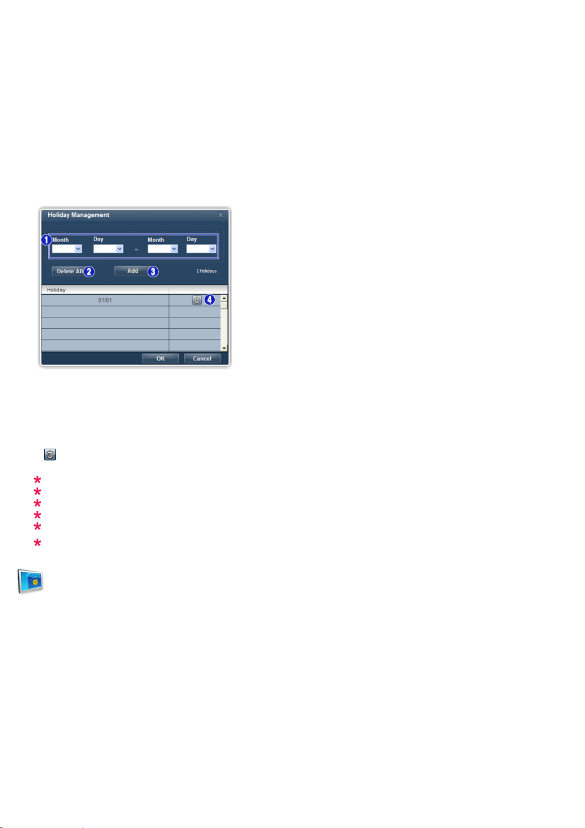
5) Holiday
- Applies the Holiday Management function to the Timer.
6) Repeat
- Available selections include Once, EveryDay, Mon~Fri, Mon~Sat, Sat~Sun, and Manual.
z
Once : The Timer goes off only once.
z
EveryDay : EveryDay: The Timer repeats daily.
z
Mon~Fri : The Timer repeats from Monday through Friday.
z
Mon~Sat : The Timer repeats from Monday through Saturday.
z
Sat~Sun : Sat~Sun: The Timer goes off on Saturday and Sunday.
z
Manual : Select a day of the week you want the Timer to go off.
2. Setting Holiday Management
The Holiday Management function specifies the dates in which the monitor will not be turned on or off by the
Timer.
1) Specifies the date.
2) Delete All
- Deletes all of the holidays.
3) Add
- Adds the specified date.
4)
- Deletes the schedule in the selected line.
The Holiday Management function can be turned on or off in the Timer setup menu.
The Input source of MagicInfo works only on MagicInfo model.
The Input source of TV works only on TV model.
Time Control is available only for the displays for which the power status is ON.
Only enabled for a TV when Source is set to TV in On Time mode.
Only enabled for a model with MagicInfo installed when Source is set to MagicInfo in On Time
mode.
PIP
PIP Size
1. Click PIP of the main icons and the PIP control screen appears.
Selects displays you want to adjust using the Select All button or checkboxes.

Info Grid shows some basic information necessary to PIP Size Control.
1) PIP Size
- Shows the current PIP Size of the display in use.
2) OFF
- Turns off the PIP of the selected display.
3) Large
- Turns on the PIP of the selected display and changes the size to Large.
4) Small
- Turns on the PIP of the selected display and changes the size to Small.
5) Double 1
6) Double 2
7) Double 3 (Picture By Picture)
- Turns on the PIP of the selected display and changes the size to Double 1.
- Turns on the PIP of the selected display and changes the size to Double 2.
- Turns on the PBP of the selected display and changes the size to Double 3.
PIP Size can be controlled with turning on the LCD Display power.
The Input source of TV works only on TV model.
The Input source of MagicInfo works only on MagicInfo model.
PIP
PIP Source
1. Click PIP of the main icons and the PIP control screen appears.

Info Grid shows some basic information necessary to PIP Source Control.
1) PIP Source
2) PC
3) BNC
4) DVI
5) TV
6) DTV
7) AV
8) S-Video
9) Component
10) HDMI1/HDMI2
11) DP
- PIP Source can be controlled with turning on the LCD Display power.
- Changes the source of the PIP of the selected display to PC.
- Changes the source of the PIP of the selected display to BNC.
- Changes the source of the PIP of the selected display to DVI.
- Changes the source of the PIP of the selected display to TV.
- Changes the source of the PIP of the selected display to DTV.
- Changes the source of the PIP of the selected display to AV.
- Changes the source of the PIP of the selected display to S-Video.
- Changes the source of the PIP of the selected display to Component.
- Changes the source of the PIP of the selected display to HDMI.
- Switches the PIP Source of the selected Display to DP.
Some of the PIP Sources may not be available for selection, depending on the input source type
of the Main Screen.
The PIP Control feature is available only for the displays whose power status is ON and the PIP
function is set to ON.
HDMI2 may not be supported depending on the product.
DP may not be supported depending on the product.
The Input source of MagicInfo works only on MagicInfo model.
HDMI2 may not be supported depending on the product.
Setting
Picture
1. Click Settings of the main icons and the Settings Control screen appears.
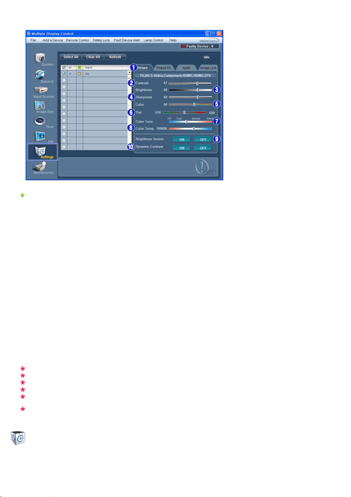
Basic information required to adjust the Picture is displayed in the main menu. Settings for the selected
monitor will be displayed if one of the connected monitors is selected, and the default settings will be
displayed if all monitors are selected by clicking All and Select. If a value is changed in this screen, the current
mode will automatically switch to custom mode.
1) Picture
- Available only for TV, AV, S-Video, Component, HDMI1, HDMI2, DTV.
2) Contrast
- Adjusts Contrast of the selected display.
3) Brightness
- Adjusts Brightness of the selected display.
4) Sharpness
- Adjusts Sharpness of the selected display.
5) Color
- Adjusts Color of the selected display.
6) Tint
- Adjusts Tint of the selected display.
- Available only for NT.
7) Color Tone
- Adjusts the Color Tone for the selected display.
8) Color Temp
- Adjusts the Color Temp for the selected display.
9) Brightness Sensor
- Adjusts the Brightness Sensor for the selected display.
10) Dynamic Contrast
- Adjusts the Dynamic Contrast for the selected display.
Brightness Sensor may not be supported depending on the product.
The Input source of MagicInfo works only on MagicInfo model.
Color Temp is only enabled if the Color Tone is set to Off.
The Input source of TV works only on TV model.
This feature is available only for the displays whose power status is ON and if no selection is
made, the factory default is displayed.
HDMI2 may not be supported depending on the product.
Setting
Picture PC
1. Click Settings of the main icons and the Settings Control screen appears.

Basic information required to adjust settings is displayed. Settings for the corresponding SET will be imported
and displayed on the slider if a display ID is selected, and the default settings will be displayed if all display IDs
are selected by clicking All and Select. If a value is changed in this screen, the current mode will automatically
switch to custom mode.
1) Picture PC
- Available only for PC, BNC, DVI and DP.
2) Contrast
- Adjusts Contrast of the selected display.
3) Brightness
- Adjusts Brightness for the selected display.
4) Red
- Adjusts red Color of the selected display.
- Available only for NT.
5) Green
- Adjusts green Color of the selected display.
- Available only for NT.
6) Blue
- Adjusts blue Color of the selected display.
- Available only for NT.
7) Color Tone
- Adjusts the Color Tone for the selected display.
8) Color Temp
- Adjusts the Color Temp for the selected display.
9) Brightness Sensor
- Adjusts the Brightness Sensor for the selected display.
10) Dynamic Contrast
- Adjusts the Dynamic Contrast for the selected display.
Brightness Sensor may not be supported depending on the product.
The Input source of MagicInfo works only on MagicInfo model.
The Input source of TV works only on TV model.
Color Temp is only enabled if the Color Tone is set to Off.
This feature is available only for the displays whose power status is ON and if no selection is
made, the factory default is displayed
DP may not be supported depending on the product.
Setting
Audio
1. Click Settings of the main icons and the Settings Control screen appears.

Basic information required to adjust Audio is displayed in the display window. Settings for the corresponding
SET will be imported and displayed on the slider if a display ID is selected, and the default settings will be
displayed if all display IDs are selected by clicking All and Select. If a value is changed in this screen, the
current mode will automatically switch to custom mode.
1) Audio
- Controls audio settings for all input sources.
2) Bass
- Adjusts Bass of the selected display.
3) Treble
- Adjusts Treble of the selected display.
4) Balance
- Adjusts Balance of the selected display.
5) SRS TS XT
- SRS TS XT Sound ON/OFF of the selected display.
6) Sound Select
- Select either Main or Sub when PIP is On.
This feature is available only for the displays whose power status is ON and if no selection is
made, the factory default is displayed.
The Input source of MagicInfo works only on MagicInfo model.
The Input source of TV works only on TV model.
Setting
Image Lock
1. Click Settings of the main icons and the Settings Control screen appears.
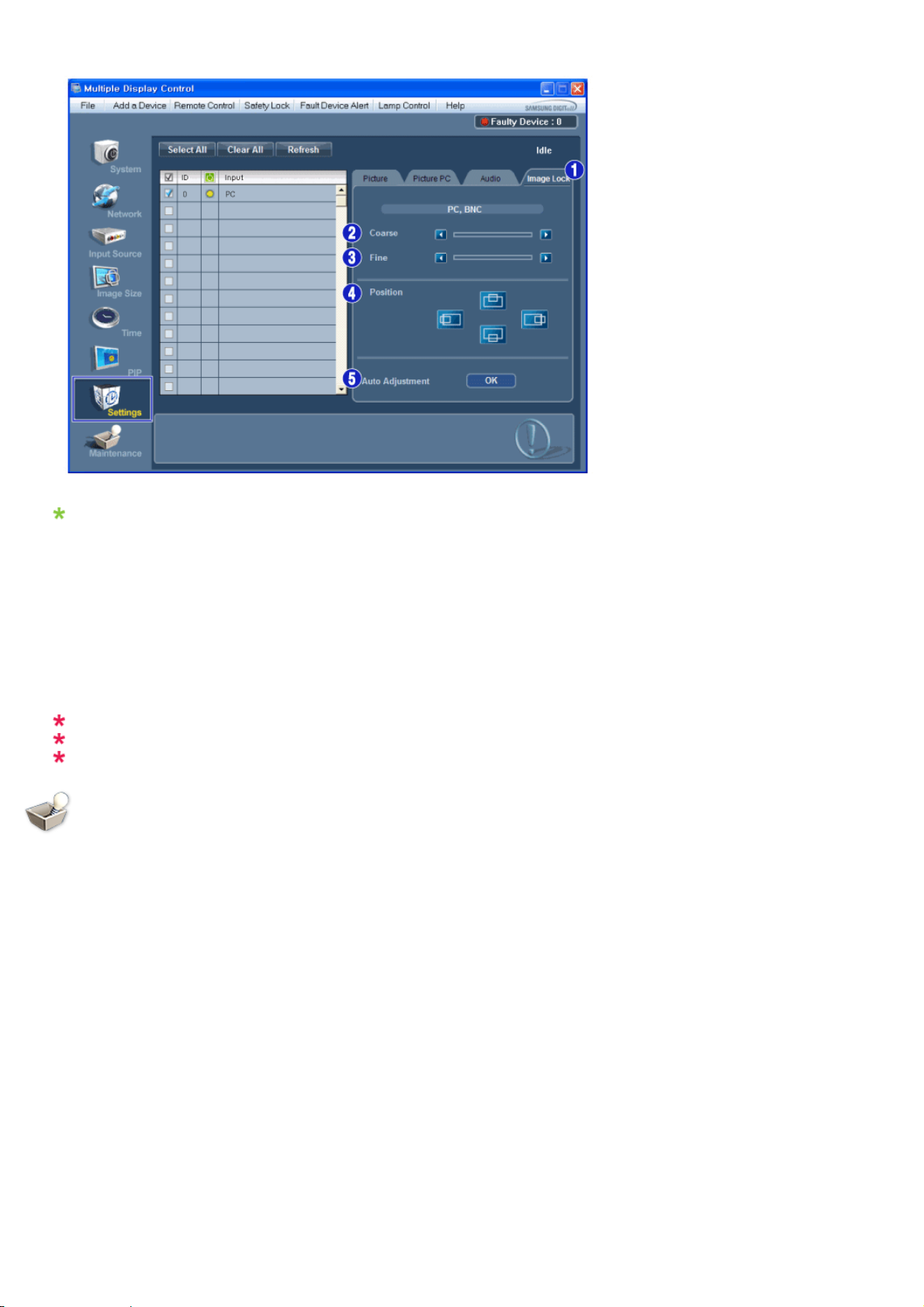
Info Grid shows some basic information necessary to Settings Control.
1) Image Lock
- Available only for PC, BNC.
2) Coarse
- Adjusts Coarse of the selected display.
3) Fine
- Adjusts Fine of the selected display.
4) Position
- Adjusts Position of the selected display.
5) Auto Adjustment
- Self-Adjust to the incoming PC signal.
The Maintenance Control feature is available only for the displays whose power status is ON.
The Input source of MagicInfo works only on MagicInfo model.
The Input source of TV works only on TV model.
Maintenance
Lamp Control
1. Click on the "Maintenance" icon in the Main Icon column to display the Maintenance screen.
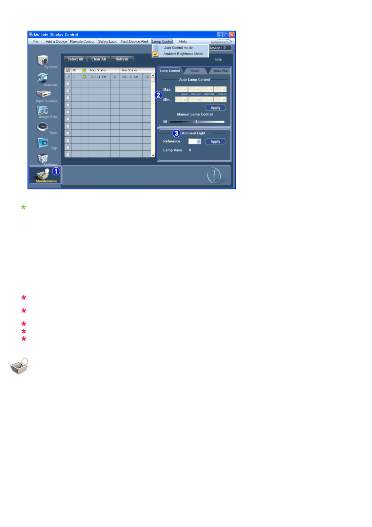
An "Info Grid" showing several basic data items appears.
1) Maintenance
- Allows the Maintenance Control function for all input sources.
2) Lamp Control
- Automatically adjusts the backlight of the selected display at a specified time.
The Manual Lamp Control automatically turns off if you adjust using the Auto Lamp Control.
- Allows you to adjust the backlight of the selected display regardless of the time.
The Auto Lamp Control automatically turns off if you adjust using the Manual Lamp Control.
3) Ambient Light
- Detects the ambient light intensity at the designated monitor and automatically adjusts the picture
brightness.
- You can specify a Reference value and designate a monitor that will automatically determine Lamp Value
(the light intensity from the lamp), based on the ambient light intensity.
Ambient Light is only supported for models that have a brightness sensor and is only enabled
when Ambient Brightness Mode is selected in the Lamp Control menu.
Auto Lamp Control and Manual Lamp Control are only enabled when User Control Mode is
selected in the Lamp Control menu.
The Maintenance Control feature is available only for the displays whose power status is ON.
The Input source of MagicInfo works only on MagicInfo model.
The Input source of TV works only on TV model.
Maintenance
Scroll
1. Click on the "Maintenance" icon in the Main Icon column to display the Maintenance screen.

1) Scroll
- This function is used to remove the afterimages that occur when a still screen is displayed on the selected
display for a long time.
2) Pixel Shift
- This allows the screen to be moved finely at the specified time interval.
3) Safety Screen
- The Safety Screen function is used to prevent afterimages from occurring when a still screen is displayed on
the monitor for a long time. The Interval item is used to set the repetition cycle in hour units and the Time
item is used to set the time when the Safety Screen function must be performed.
The Type item can be set to Scroll, Pixel, Bar, Eraser, All White, or Pattern.
4) Safety Screen2
- This function is used to prevent afterimages from occurring. There are five (5) types that you can select and
control with this function.
For the Scroll type, the Time item can be set to 1, 2, 3, 4 or 5. For the Bar and Eraser types, it can be
set to 10, 20, 30, 40 or 50. For the All White and Pattern type, it can be set to 1, 5, 10, 20 or 30.
The Maintenance Control feature is available only for the displays whose power status is ON.
The Input source of MagicInfo works only on MagicInfo model.
The Input source of TV works only on TV model.
Maintenance
Video Wall
1. Click on the "Maintenance" icon in the Main Icon column to display the Maintenance screen.

1) Video Wall
- A Video Wall is a set of video screens that are connected together, so that each screen shows a part of the
whole picture or so that the same picture is repeated on each screen.
2) Video Wall Control
- Video Wall properties can be configured.
1) On / Off
- Turns on/off the Video Wall function of the selected display.
2)
Format
- The format can be selected to see a divided screen.
z
Full

z
Natural
3) Video Wall (Screen divider)
- The screen can be divided into.
You can select a number of screens with a different layout when dividing.
z
Select a mode from Screen divider.
z
Select a display from Display Selection.
z
The place will be set up by pressing a number in the selected mode.
z
The maximum number of monitors that can be arranged: Horizontal X Vertical = 100
z
Up to 15 monitors can be arranged in a row. The maximum value for Horizontal is 6 if Vertical is set to 15
while the maximum value for Vertical is 6 if Horizontal is set to 15.
4) Viewing Screen Splits
- You can view and change the layout of screens using the Screen Divider settings.
The range of the Screen Divider setting may differ depending on the model.
You may not operate this function in MagicInfo.
The Input source of TV works only on TV model.
The Maintenance Control function is available only for the displays where the power status is ON.
Troubleshooting
1. The display you wish to control does not appear on the System Info Grid
- Check if the entered IP address is correct and check the connection status of the Ethernet cable.
- Check the displays to see if any of the other displays connected have the same ID. If more than one displays
have the same ID, those displays are not properly detected by the program due to data conflict.
- For monitors that support a Set ID between 0 to 99, you have to set the Set ID to a value between 0 and 99.
Note : Check if the Set ID of the monitor is a value between 0 and 99 (set the value using the Display
menu).
2. The display you wish to control does not appear on the other Control Info Grids
- Check to see if the display power is ON. (You can check this in System Info Grid)
- Check if you can change the input source of the display.
3. The dialogue box appears repeatedly.
- Check to see if the display you wish to control is selected.
4. Both On Timer and Off Timer have been set but different time is showing.
- Apply current time to synchronize the display clocks.
5. The remote may not function properly when you turn off the remote Function, disconnect the Ethernet cable, or
exit the program in an Irregular manner. Rerun the program and turn the remote function again to Restore normal
functions.
<Note> This program may malfunction due to problems in communication circuits or interference from electronic
appliances nearby.
Settings Value Display In Multiple Display Mode
When there are more than one displays connected, the settings values are displayed as follows.
1. No selection: Displays the Factory Default Value.
2. Selected one display: Fetches and displays the settings value for the selected display.
3. Selected one display (ID1) and add another display (ID3): The program, which was displaying the settings
4. If all sets are selected at the same time by clicking All and Select, the default value will be restored.
value of ID 1, fetches and displays the value of ID3.


Adjusting the LCD Display
Input
Available Modes
•
PC / DVI / DP
•
AV
•
Component
•
HDMI
•
MagicInfo
•
TV
Note
• MagicInfo can only be enabled when a network box(sold separately) is connected.
•
A TV tuner box (sold separately) must be connected to use the TV.
Source List
Use to select PC, HDMI or other external input sources connected to the LCD Display. Use to select
the screen of your choice.
1. PC
2. DVI
3. AV
4. Component
5. HDMI1
6. HDMI2
7. DisplayPort
8. MagicInfo - Enabled if a network box is connected.
9. TV- Enabled if a TV tuner box is connected.

Adjusting the LCD Display
Note
The [RGB/COMPONENT IN] port is compatible with a PC or component input.
PIP
PIP
However, the picture
connected input source.
Note
The PIP function is not available when Video Wall is On.
When external AV
to watch video from those devices in a small window super-imposed on the PC Video signal. (Off/
On)
Note
• PIP turns off when the LCD Display is switched to an external source.
•
If you select , , in Size, Position and Transparency will not be activated.
may not display normally if you select an input source different from the actual
devices such as VCRs or DVDs are connected to the LCD Display, PIP allows you
Source
Turns the PIP Screen Off/On.
• Off
• On
Selects the input source for the PIP.
Note
• PIP is disabled if the primary screen does not receive a signal.
• A TV tuner box (sold separately) must be connected to use the TV.
 Loading...