


 Loading...
Service Manual
(Empty page)

SAMSUNG MEDISON
DIAGNOSTIC ULTRASOUND SYSTEM
RS80A
Service Manual
English
SM-RS80A-ENG-01
(Empty page)
Safety Requirements
■Categorization
−Type of protection against electric shock: Class I
−Degree of protection against electric shock (when the patient is in physical contact): Type BF or type CF applied part
−Degree of protection against the ingress of harmful liquids: General equipment
−Degree of safety of use in the presence of flammable anesthetic agent mixed with air, oxygen, or nitrous oxide: Not suitable for use near flammable anesthetic agent mixed with air, oxygen, or nitrous oxide
−Mode of operation: Continuous operation
■Safety standards the device conforms to
−Medical electrical equipment, part 1: General requirements for basic safety and essential performance IEC 60601-1:2005/A1:2012
−Medical electrical equipment, part 1-2: General requirements for basic safety and essential performance - Collateral standards: Electromagnetic compatibility - Requirements and tests IEC 60601-1-2:2007
−Medical electrical equipment, part 1-6: General requirements for basic safety and essential performance - Collateral standards: Usability IEC 60601-1-6:2010
−Medical electrical equipment, part 2-37: Particular requirements for the basic safety and essential performance of ultrasonic medical diagnostic and monitoring equipment IEC
60601-2-37:2007
−Medical electrical equipment, part 1: General requirements for safety IEC 60601-1:1988,
A1:1991, A2:1995
−Medical electrical equipment, part 1-1: General requirements for safety - Collateral standards: General requirements for medical electrical systems IEC 60601-1-1:2000
−Medical electrical equipment, part 1-2: General requirements for safety - Collateral standards: Electromagnetic compatibility - Requirements and tests IEC 60601-1-2:2001,
A1:2004
−Medical electrical equipment, part 1-4: General requirements for safety - Collateral standards: Programmable electrical medical systems IEC 60601-1-4:1996, A1:1999

−Medical electrical equipment, part 2-37: Particular requirements for the basic safety and essential performance of ultrasonic medical diagnostic and monitoring equipment IEC
60601-2-37:2001, A1:2004, A2:2005
−Medical devices - Application of risk management ISO 14971:2007
−Medical electrical equipment, part 1: General requirements for safety UL 60601-1:2003
−Medical electrical equipment, part 1: General requirements for safety CAN/CSA C22.2
No. 601.1-M90:1990, R2003, R2005
−Biological evaluation of medical devices – part 1: Evaluation and testing ISO 10993-1:
2009
−Standard means for reporting the acoustic output of medical diagnostic ultrasonic equipment IEC 61157:2007
■Statements
The “C” and “US” of the CSA mark certifies that the product conforms to applicable Canadian and American standards and has been certified by Canadian and American certification agencies.
This mark certifies that the product conforms to applicable EEC standards and has been certified by the European certification agency.
This mark certifies that the product conforms to applicable EEC standards.
GMP symbol represents the Good Manufacturing Practice and quality standards in accordance with the Korean Quality Standards.

Precautions for Use
Be sure to read this operation manual thoroughly, to familiarize yourself with the operation of the product and the relevant safety information, before attempting to use the product.
■Keep this manual near the product and refer to it when using the product.
■Please familiarize yourself with the safety precautions in ‘Chapter 2. Safety’ and ‘Chapter 10. Maintenance’, in particular, contain important safety information and must be thoroughly understood.
■This manual does not include diagnosis results or opinions. Also, check the reference information for the measured area of the body before using the application’s measurement results in any diagnosis.
■This product is an ultrasound diagnosis device and cannot be used from the user’s PC. The manufacturer is not responsible for any problems that may be caused by such attempts.
■This product must only be used by persons who are trained and/or certified to operate clinical diagnostic devices. Unqualified persons must not use this product.
■The manufacturer is not responsible for any damage to this product caused by user carelessness and/or neglect.
■Product orders are based on individually agreed specifications and may not include all functions specified in this manual.
■Some functions, options, or probes may not be available in certain countries or regions.
■All reference material on standards, regulations, and related revisions are valid at the time of the publication of this manual.
■Screen images in this manual are examples and may differ from the actual screen or system.
■The content and specifications described in this manual are subject to change without prior notice.
■Products that are not manufactured by Samsung Medison are indicated with the trademarks of their respective owners.
■The following terms are used to highlight safety precautions that the user must be aware of:
|
|
|
|
|
|
DANGER |
|
|
Disregarding this instruction may result in death, serious injury, or other |
|
|
|
dangerous situations. |
|
|
|
|
|
|
|
|
|
|
|

WARNING Follow these instructions to prevent a serious accident, or damage to property.
CAUTION Follow these instructions to prevent a minor accident, or damage to property.
The accompanying information covers an installation, operation, or
NOTE maintenance procedure that requires careful attention from the user, but has little chance of leading directly to a dangerous situation.
If You Need Assistance
Contact the Samsung Medison customer service department or your local vendor if you need a service manual or any other support for the product.

Chapter 1 |
|
Introduction |
|
Product Specifications ................................................................................ |
3 |
Product Configuration................................................................................. |
6 |
Monitor ................................................................................................................ |
8 |
Control Panel .................................................................................................... |
11 |
Console............................................................................................................. |
18 |
Peripheral Devices............................................................................................ |
20 |
Probe ................................................................................................................ |
23 |
Clear Track ....................................................................................................... |
24 |
Accessories ...................................................................................................... |
24 |
Optional Features ............................................................................................. |
25 |
Chapter 1 Introduction 1 - 3
Product Specifications
Physical
Dimensions
Imaging modes
Gray Scale
Focusing
Probes
(Type BF / IPX7)
Probe connections
Height: 1,342mm (with monitor) Width: 560mm
Depth: 980mm
Weight: 140kg (with monitor)
Weight: Approx. 155kg (with Safety Working Load)
2D Mode
M-Mode Color Doppler
Pulsed Wave (PW) Spectral Doppler Continuous Wave (CW) Doppler Tissue Doppler Imaging (TDI) Tissue Doppler Wave (TDW)
Power Doppler (PD) S-Flow
ElastoScan Mode Color M-Mode Anatomical Mode 3D imaging Mode 4D imaging Mode
256 (8 bits)
Transmit focusing, maximum of eight points (four points simultaneously selectable)
Digital dynamic receive focusing (continuous)
Linear Array: L3-12A, L5-13, L7-16, LA2-9A, LA3-16A,
LA3-16AI
Curved Array: C2-6, CA1-7A, CA2-8A, CF4-9, E3-12A
3D: V4-8, V5-9, LV3-14A
Phased Array: PE2-4, PM1-6A
CW: CW6.0
Five Active Probe Ports (include one CW probe connector)

1 - 4 RS80A Service Manual
Monitor
ECG
Rear Panel
Input / Output
Connections
Image Storage
Application
Electrical
Parameters
Measurement
Packages
Signal processing (Pre-processing)
Signal processing (Post-processing)
Main Monitor
23 inch LCD monitor (LED backlight unit) called "LCD monitor" henceforth
Touch Screen Monitor
13.3 inch LCD monitor (LED backlight unit) called "LCD monitor" henceforth
USB Type (Type CF)
Audio in / out
Microphone
External Trigger in / out
External monitor DVI-I
Network
USB
Foot Switch
Maximum 12,700 frames for Cine memory
Maximum 8,192 Lines for Loop memory
Image filing system
Obstetrics, Gynecology, Urology, Abdomen, Vascular, Small Part, Pediatric, MSK, Contrast, Cardiac, TCD
100-240V~, 1400VA, 50/60Hz
OB, Gynecology, Cardiac, Vascular, Fetal Heart, Urology, Abdomen, Small Parts, Musculoskeletal, TCD, Pediatric Hips * Refer the Chapter 9 for additional information
TGC control
Mode-independent gain control
Acoustic power control (adjustable)
Dynamic aperture
Dynamic apodization
Dynamic range control (adjustable)
Image view area control
M-Mode sweep speed control
Frame average
Edge Enhancement / Blurring

Chapter 1 Introduction 1 - 5
Measurement
Auxiliary
User Interface
Pressure Limits
Humidity Limits
Temperature Limits
Gamma-scale windowing
Image orientation (left/right and up/down, rotation) White on black/black on white
Zoom
Trackball operation of multiple cursors
2D Mode: Linear measurements and area measurements using elliptical approximation or trace
M-Mode: Continuous readout of distance, time, and slope rate Doppler mode: Velocity and trace
USB Video Printer
USB Line Printer
USB to RS-232 Serial Cable
Foot Switch (IPX8)
USB Flash Memory Media
USB HDD
English, German, French, Spanish, Italian, Russian, Chinese
Operating: 700 – 1,060hPa
Storage: 700 – 1,060hPa
Operating: 30 – 75%
Storage & Shipping: 20 – 90%
Operating: 10 – 35 C
Storage & Shipping: -25 – 60 C
1 - 6 RS80A Service Manual
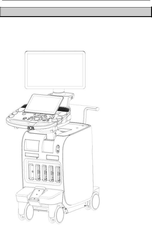
Product Configuration
This Product consists of monitor, control panel, console, peripheral devices and probes.
Monitor
Touch Screen
Control Panel
Probe Holder
Place for Gel WarmerCable Holder
DVD Drive
CW Probe PortECG Port
Clear Track (Optional)Probe Port
BrakeAir FilterWheels
[Figure 1.1 Product Front View]
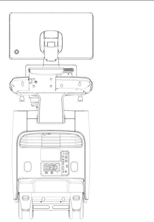
Chapter 1 Introduction 1 - 7
Monitor Arm
USB Port
Motorized Lift
Storage Compartment
Handle
Air Vent
Power Receptacle
Rear Panel
Cable Holder
[Figure 1.2 Product Rear View]
1 - 8 RS80A Service Manual
Monitor
Ultrasound images and other information are displayed on the color LCD monitor.
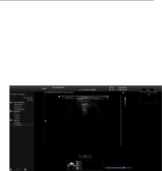
▐ Screen Layout
The monitor displays ultrasound images, operation menus and a variety of other information. As shown in the image below, the screen consists of the Title area, Preset Change and Ez Exam area, Image area, Thumbnail area, User Information, and User defined key area.
[Figure 1.3 Screen Layout]
Title Area
Displays patient information, hospital name, application, frame rate, depth, probe information, acoustic output information, and the current date and time.
Preset Change and Ez Exam area
Displays Preset Change. You can quickly change the preset of a probe. If you are using Ez Exam, the Ez Exam menu will be displayed.

Chapter 1 Introduction 1 - 9
You can set up the Ez Exam menu in Ez Exam Setup. NOTE For more information, please refer to ‘Chapter 3.
Utilities’.
Image Area
Displays ultrasound images. TGC, image information, annotation, and measurement information are also displayed.
Thumbnail Area
Images saved by selecting Save are displayed as thumbnails. If saving Single screens, up to 5 images are shown in a list; for Quad screens, up to 20 images can be displayed. Clicking with the pointer will enlarge the selected thumbnail in the Image area.
User Information Area
Information that is useful to the user, such as current system status, image information, selectable items, etc., is displayed.
User Key (User Defined Key) Area
Settings for User Defined Keys, including the positions of Set and Exit, are displayed. You can change the setting of each button in
Key.
NOTE |
For information on User Key Setup, please refer to |
|
‘Chapter 3. Utilities’. |
||
|

1 - 10 RS80A Service Manual
Principles of Operation of Diagnostic Ultrasound System
Medical ultrasound images are created by digital memory and computer when they convert the high-frequency wave signals that are transmitted and received by the probe.
As ultrasound waves propagate through the human body, they generate reflected signals whenever they encounter a change in density. For example, reflected signals are generated when signals pass from fatty tissues to muscle tissues. Reflected signals return to the probe where they are converted into electronic signals. The reflected signals are amplified and processed by analog and digital circuits that have filters for various frequencies and response time options. Then, they are again converted into high-frequency electronic signals, and saved as a series of digital image signals. The monitor displays the image signals stored in the storage device in real time.
The entire process of transmitting, receiving, and processing signals is controlled by the computer.
Chapter 1 Introduction 1 - 11
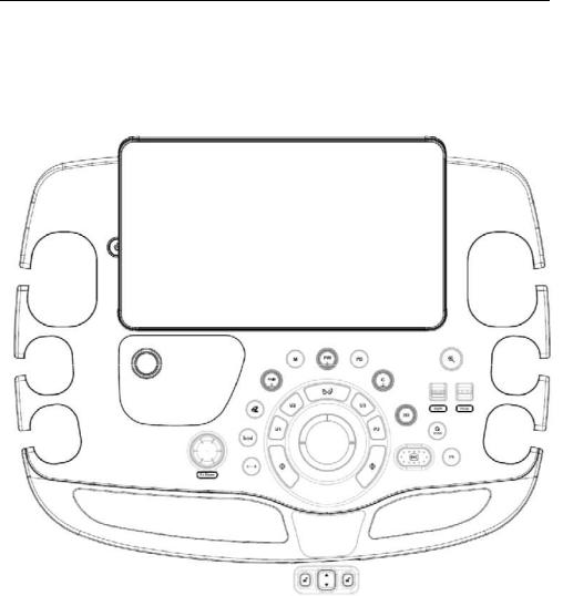
Control Panel
You control the system by using the control panel.
[Figure 1.4 Control Panel]
The control panel consists of soft menus, buttons, dials, dial-buttons, slider, and track.
The dial-button can be used both as a dial and a button.

1 - 12 RS80A Service Manual
▐ Functions of the Control Panel
The following are the descriptions and instructions for the controls on the control panel. For more information on controls with multiple functions, see Chapter 3 and later in this manual.
On/Off |
Button |
Turns the system on/off. |
|
|
|
||
|
|
|
|
2D |
Dial-button |
Button: Starts 2D Mode. |
|
Dial: Adjusts the 2D gain. |
|||
|
|
||
|
|
|
|
M |
Button |
Start or end M-Mode. |
|
|
|
|
|
PD |
Button |
Press this button to start/stop Power Doppler mode. |
|
|
|||
|
|
|
|
|
|
Button: Press this button to start/stop PW Spectral |
|
PW / Y |
Dial-button |
Doppler mode. |
|
Dial: Adjusts the PW gain. In 3D View, rotates the |
|||
|
|
||
|
|
image along the Y-axis. |
|
|
|
|
|
|
|
Button: Press this button to start/stop Color Doppler |
|
C / Z |
Dial-button |
mode. |
|
Dial: Adjusts the C gain. In 3D View, rotates the |
|||
|
|
||
|
|
image along the Z-axis. |
|
|
|
|
|
|
|
Button: Adjusts the angle of the sample volume in |
|
Angle / X |
Dial-button |
Spectral Doppler mode. It is also used to adjust the |
|
BodyMarker’s probe cursor or indicator angle. |
|||
|
|
||
|
|
Dial: In 3D View, rotates the image along the X-axis. |
|
|
|
|
|
Depth |
Switch |
Adjusts the scanning depth of the image. |
|
|
|
|
|
Focus |
Switch |
Changes location and number of focus on the target |
|
location you wish to study. |
|||
|
|
||
|
|
|
|
Zoom |
Dial-button |
Magnifies an image. |
|
|
|
||
|
|
|
Chapter 1 Introduction 1 - 13
|
|
Press this button to turn the Quick Scan function on. |
|
Q scan |
Button |
The ‘Q scan’ mark will appear at the top of the |
|
image. It can be used only in specific applications of |
|||
|
|
||
|
|
specific probes. |
|
|
|
|
|
Freeze |
Button |
Pauses/resumes scanning. |
|
|
|
||
|
|
|
|
|
|
Stands for User Key; functions can be assigned to |
|
U 1~3 |
Button |
these buttons as desired. The function of each |
|
button can be set in Setup > User Defined Key. The |
|||
|
|
settings are displayed in the User Defined Key area |
|
|
|
in the monitor. |
|
|
|
|
|
|
|
Stands for Peripheral Key; functions can be |
|
P 1~2 |
|
assigned to these buttons as desired. The function |
|
Button |
of each button can be set in Setup > User Defined |
||
|
Key. The settings are displayed in the User Defined |
||
|
|
||
|
|
Key area in the monitor. |
|
|
|
|
|
|
|
This button is used to assign user-defined |
|
|
|
functions. The function of each button can be set in |
|
|
|
Setup > User Defined Key. |
|
|
Button |
Set: Select an item or value using the trackball. Also |
|
Set/Exit |
used to change the function of the trackball. |
||
|
|||
|
|
Exit: Exits the function currently being used and |
|
|
|
returns to the previous state. |
|
|
|
|
|
Ez Exam |
Dial-button |
Uses the Ez Exam and Preset Change features. |
|
|
|
|
|
|
Button |
Deletes text, indicators, BodyMarkers, |
|
Clear |
measurement results, etc. displayed on an image. |
||
|
|||
|
|
|
|
|
Button |
Switch the trackball's current function to the next |
|
Change |
supported function. |
||
|
|||
|
|
|
|
Calculator |
Button |
Start measurements for the application. |
|
|
|
||
|
|
|
|
Caliper |
Button |
Start taking basic measurements such as distance, |
|
circumference, area, and volume. |
|||
|
|||
|
|
||
|
|
|
|
Trackball |
Trackball |
Moves the cursor on the screen. Also scrolls |
|
through Cine images. |
|||
|
|
||
|
|
|

1 - 14 RS80A Service Manual
Soft Menu Selects Soft Menu or changes the settings of the
Dial-button: selected Soft menu.
▐ Touch Screen
The touch screen is an operating tool that can be touched by the user to input data. The functions that are available in the current mode are shown in the form of buttons or a dial-button.
Touch Screen Layout
|
|
|
[Figure 1.5 Touch Screen]
These buttons are always displayed on the touch screen. Buttons that are in use are shown in blue, and buttons that cannot be used are deactivated.
Patient |
Displays the Patient Information screen, which is used for selecting a |
|
patient ID from the list or entering new patient information. |
||
|
Finishes the exam of the currently selected patient and resets the End Exam related data.
Probe |
Displays the Probe Selection screen to select or change the probe |
|
and application. |
||
|

Chapter 1 Introduction 1 - 15
Report |
Displays the Report screen, which shows the summary of |
|
measurement results of the current application. |
||
|
SonoView Launches SonoView, an image filing program.
Pointer |
Displays an arrow-shaped pointer on the screen. This can be used in |
|
Diagnosis mode. |
||
|
||
|
|
|
3D |
Starts or ends 3D mode. |
|
|
|
|
Setup |
Displays the Setup screen, where you can change the various |
|
settings of the product. |
||
|
Displays the mode that is currently in use.
The current Diagnosis mode and Utility are displayed in separate tabs. The tab currently in use is shown in blue; pressing the tab changes the content of the touch screen.
Changing Touchscreen Tabs
You can also change tabs by performing a page-turn action by dragging on the touch screen.
The menu items that are available in the current input mode are shown as buttons. The menu currently in use is shown in blue.
These buttons are always displayed on the touch screen. Buttons that are in use are shown in blue, and buttons that cannot be used are deactivated.
Back |
Exits the current screen and returns to the previous state. |
Exit
Exits the function currently being used and returns to the Scan mode.
Quad
Changes to Quad mode. Up to four images are displayed on the screen.
Single
Changes to Single mode. Only one image is displayed on the screen.
Dual
Changes to Dual mode. Up to two images are displayed on the screen.
BodyMarker Changes to the BodyMarker screen.

1 - 16 RS80A Service Manual
Annotation Changes to the Annotation screen.
Keyboard Displays the Screen Keyboard.
[Figure 1.6 Screen Keyboard]
This is the TGC area. Ten sliders for controlling Gain are displayed here. Moving the slider to the right increases the Gain, which makes the image brighter. TGC stands for Time Gain Compensation.
An excessively large difference between the Gain value CAUTION settings of adjacent TGC sliders may cause stripes to
appear in an image.
The Soft Menu items that are available in the current input mode are shown. The menu currently in use is shown in blue. Tap a touch screen button or use the Soft Menu dial-button on the control panel to change settings.
Changes the page of the touch screen.

Chapter 1 Introduction 1 - 17
▐ Adjusting the Control Panel
|
|
Do not apply excessive force to the control panel. |
CAUTION |
|
To transport the product, use the handle at the rear of |
|
||
|
|
the console. |
|
|
|
Adjusting Left-Right/Forward-Back
Press and hold one of the two  buttons at the center of the control panel handle, and move carefully to the left or right to adjust the position. Release the button to fix the control panel in the current position.
Moving Up and Down
Press the  automatic switch located at the center of the control panel handle to adjust the position vertically.
1 - 18 RS80A Service Manual
Console
The console consists of the interior and the exterior. The interior of the console mainly contains devices that produce ultrasound images. On the exterior of the console are various connectors, probe holder, storage compartment, handle, wheels, etc.
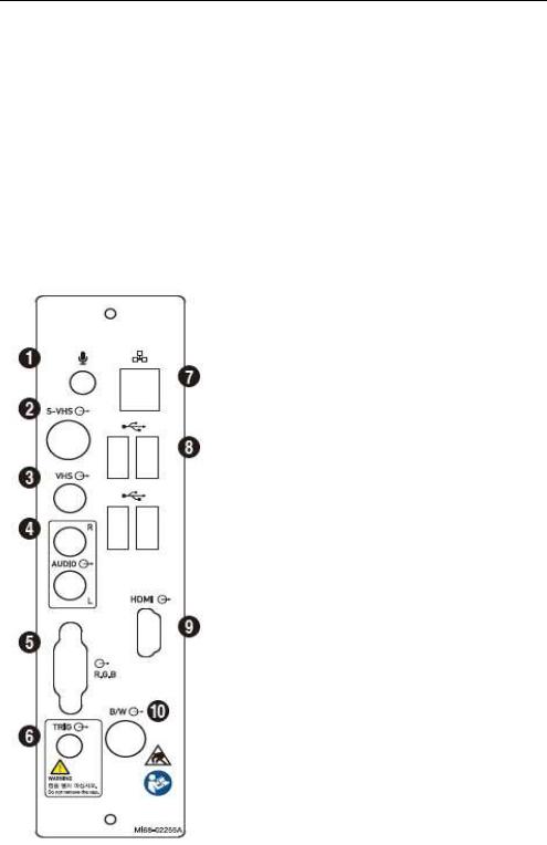
▐ Rear Panel
Rear Panel is located at the back of the product; it connects the system to the monitor and other peripheral devices.
Microphone Port (Input): Connects a microphone.
S-VHS port (Output): Provides an S-VHS connection for a VCR.
VHS Port (Output): Provides a VHS connection for a VCR.
Audio Port (Output): Outputs audio signal.
RGB Port (Output): Provides analog RGB signal output (supports 1280*1024 resolution).
Trig Port (In/Out): Not used.
Network Port (Input/Output): Used to connect to a network. Via DICOM network, patient information can be transferred to other servers.
USB Port (Input/Output): Used to connect to USB peripheral devices.
HDMI Port (Output): Outputs digital signals to the monitor. Use of a DVI monitor via a DVI adapter or cable is not recommended (supports 1920x1080 resolution only).
B/W Port (Output): Not used.
[Figure 1.7 Rear Panel]

Chapter 1 Introduction 1 - 19
▐ Power Receptacle
The power connection part is located at the bottom on the rear panel.
[Figure 1.8 Power Receptacle]
Power Outlet (Input): The power supply inside the product supplies electricity to external peripheral devices.
Power Inlet: Accepts the power cord, which connects to an external power supply.
Power Switch: Supplies or cuts power to the entire system.
Equipotential terminal: Must be connected to the equipotential bonding in a treatment room.
▐ Probe Holder
Probe holders are mounted at the left and right sides of the control panel.
1 - 20 RS80A Service Manual
Peripheral Devices
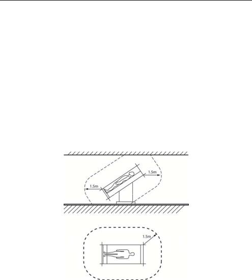
Peripheral devices can be connected to their corresponding ports on the left/right or rear sides of the console.
|
|
|
■ Do not install peripheral devices that are not listed in this |
|
|
|
manual within the patient environment. If you install an |
|
CAUTION |
|
unlisted device in the patient environment, it may cause an |
|
|
electrical hazard. |
|
|
|
|
■ Do not connect additional peripheral devices to socket of the |
|
|
|
auxiliary socket. Doing so may decrease the safety level. |
|
|
|
|
[Figure 2.9 Patient Environment]
|
NOTE |
|
|
For instructions on operating a peripheral device, please refer to the |
|
|
|
|
operation manual for the device. |
|
|
|
|
|
|
|
|
|
|
|
|
|
|

Chapter 1 Introduction 1 - 21
▐ Internal Peripheral Devices
These are peripheral devices mounted inside the system.
DVD-Multi
DVD-RW, DVD+RW, DVD-R, DVD+R, CD-R, CD-RW, CD-ROM
Hard Disc Drive
Min. 64Gbytes SATA SSD
▐External Peripheral Devices
External peripherals are mounted when their use is desired by the user; they are usually connected via appropriate ports on the Rear Panel.
When using a peripheral device via a USB port, always turn the power off before connecting/disconnecting the device.
CAUTION Connecting or disconnecting a USB device while power is turned on may cause the system and/or the USB device to
malfunction.
Use Utility > Storage Manager to mount or dismount a removable disk.
USB ports are located on the console and the Rear
NOTE
Panel.
We recommend that you connect USB storage devices (flash memory media, etc.) to the ports on the console, and other USB peripheral devices to the Rear Panel for convenience.
The following products are recommended:
USB Video Printer
-BW: Mitsubishi P-95DE, Sony UP-D897, Samsung ML-2955DW
-Color: Mitsubishi CP-30DW, Sony UP-D25MD, Samsung CLP-615ND

1 - 22 RS80A Service Manual
■You must install a printer and drivers that are compatible with the English version of Microsoft Windows 7TM . Contact Samsung Medison customer support division for inquiries about printer driver installation.
■When connecting a printer, make sure that it is the same as
CAUTION |
the printer that is configured in Microsoft WindowsTM or |
|
Setup. |
■Please note that different printers are connected via different ports. Printers should be connected to the printer port while the USB printer should be connected to the USB port.
USB to RS-232C Serial Cable
USB to Serial (RS-232C) Converter with FTDI Chipset (FTDI FT232BM Compatible)
|
NOTE |
|
For more information about the Open Line Transfer, |
|
|
refer to ‘Chapter 9. Probes’. |
|
|
|
||
|
|
|
|
Foot Switch
-3 Pedals HID Type
To assign functions to the foot switch, go to Setup > Peripherals > Foot Switch. You may select Freeze, Update, Record, Print1, Save, Store Clip, Volume Start, or Ez Exam.
Other
Flash Memory Media
■ If you are using USB 1.1 flash memory, the
|
system may fail to recognize the device. Remove |
|
|
the flash memory from the console and equip |
|
|
again with an appropriate device. |
|
NOTE |
||
■ When using a flash memory device which |
||
|
||
|
supports functions other than saving files, please |
|
|
check first to see if it is possible to save the file on |
|
|
a desktop PC. |
Loading...