

Page 1
Installation Instructions
!
!
➊
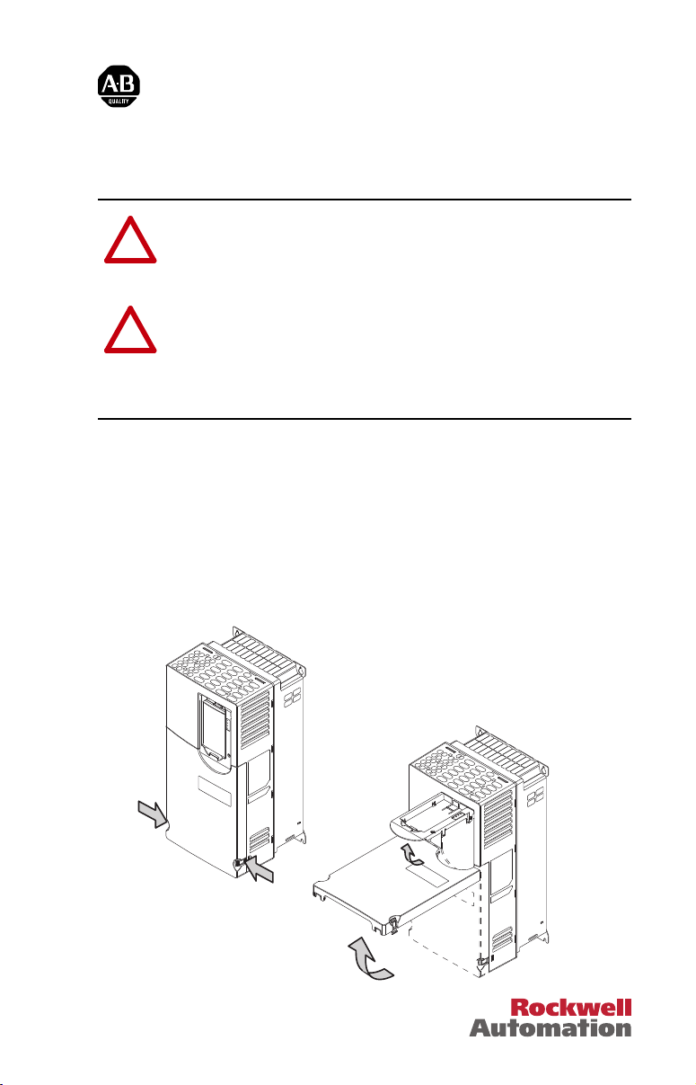
Remove power from the drive.
➋
Remove the drive cover and lift up the drive HIM cradle (with or without
the HIM installed) to its open position to access the drive control pod.
Network Communication Option Module
(for use with PowerFlex
ATTENTION: Risk of injury or death exists. The PowerFlex
750-Series drive may contain high voltages that can cause injury or
death. Remove power from the drive, and then verify power has been
discharged before removing the drive cover.
ATTENTION: Risk of equipment damage exists. The network
communication option module contains electrostatic discharge (ESD)
sensitive parts that can be damaged if you do not follow ESD control
procedures. Static control precautions are required when handling the
card. If you are unfamiliar with static control procedures, see Guarding
Against Electrostatic Damage, publication 8000-4.5.2.
Important: For the PowerFlex 20-750-PBUS Profibus option module, disregard
these instructions. Instead, see its User Manual, publication
750COM-UM004, for special installation instructions.
®
750-Series Drives)
Page 2
2
➌
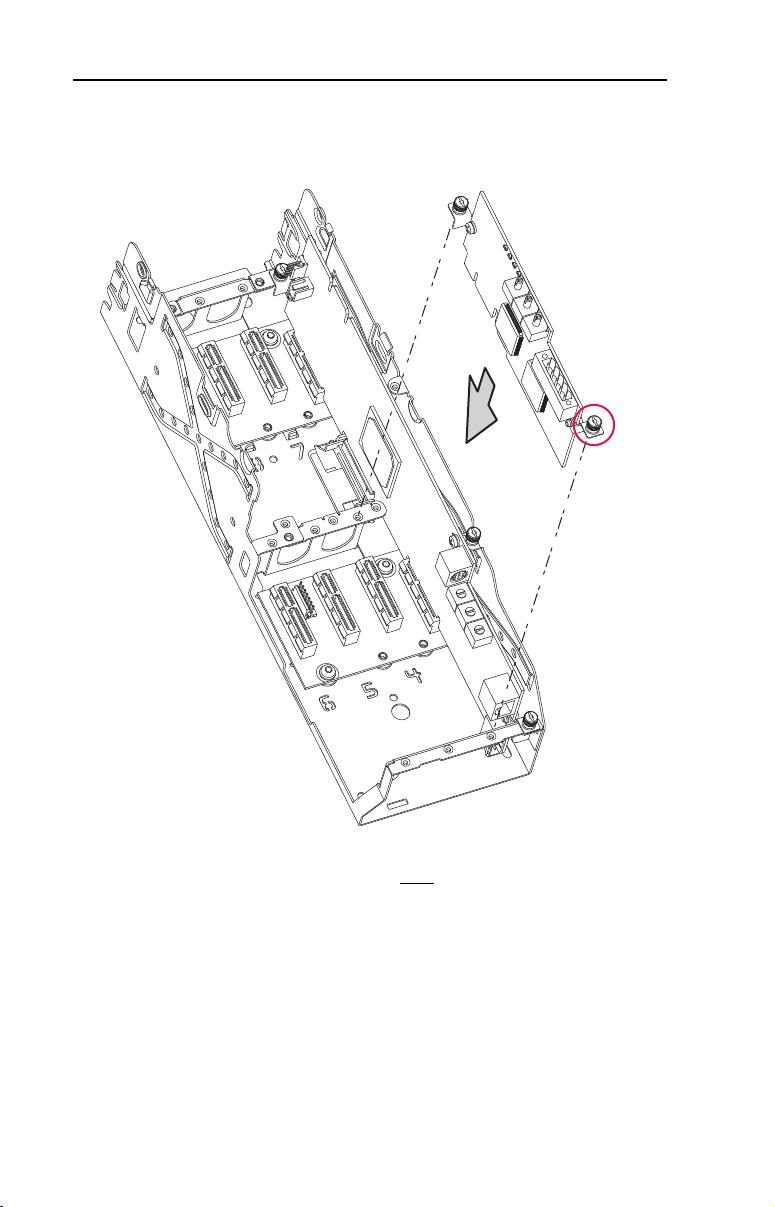
Insert the network communication option module into drive Port 4, 5 or 6.
Make sure the module is fully seated into the connector.
DETAIL A
➍
Important: If a PowerFlex 20-750-PBUS Profibus option module resides
in the adjacent port to the right
of the port in which the new
module is being installed—and the lower mounting screw of
the new module is a T15 Torx head screw (shown in DETAIL
A above)—that screw may electrically contact the metal
Profibus cable connector attached to the Profibus option
module. This may cause faulty operation. To prevent this,
perform steps 4-A through 4-C below. If a PowerFlex
20-750-PBUS Profibus option module is not in that port,
disregard these steps and proceed to step 5.
A. Remove the lower mounting screw, a T15 Torx head screw shown in
DETAIL A above, from the new module being installed.
Page 3

3
B. Replace the larger T15 Torx head screw with the smaller spare T8 Torx
head mounting screw that was shipped with the PowerFlex
20-750-PBUS Profibus option module.
C. Proceed to step 5.
TIP: To remove the captive T15 Torx head screw, the module must
be removed to back the screw out of the mounting clip.
➎
Tighten both of the option module mounting screws to the pod mounting
bracket to properly ground the module to the drive. Tighten both screws to
the recommended torque shown below.
0.45-0.67 N•m
(4.0-6.0 lb•in)
2 Places
Page 4

➏
See the network communication option module User Manual for complete
installation, setup, and communication instructions. To view or download
its User Manual, perform the following steps.
A. Go to Rockwell’s Literature Library website at
www.rockwellautomation.com/literature
.
B. From the ‘Search library by:’ pulldown menu, choose Publication
Number.
C. Enter ‘750COM-UM’ in the search field below.
D. From the search list results, find the appropriate option module User
Manual.
E. Right-click the PDF document icon in the PDF column, and select
‘Save Target As’.
F. Create or use an existing folder, and download the manual.
For information such as firmware updates and answers to drive-related
questions, go to the Drives Service & Support website at http://
www.ab.com/support/abdrives and click on the ‘Downloads’ or
‘Knowledgebase’ link.
www.rockwellautomation.com
Americas: Rockwell Automation, 1201 South Second Street,
Milwaukee, WI 53204-2496 USA,
Tel:
(1) 414.382.2000, Fax: (1) 414.382.4444
Europe
/
Middle East/Africa: Rockwell Automati
on,
Pegasus Park, De Kleetlaan 12a,
1831 Diegem, Belgium,
Tel: (32) 2 663 0600, Fax: (32) 2 663 0640
Asia Pacific: Rockwell Automation, Level 14, Core F, Cyberport 3, 100 Cyberport Road, Hong Kong, Tel: (852) 2887 4788, Fax: (852) 2508 1846
Power, Control and Information Solutions Headquarters
U.S. Allen-Bradley Drives Technical Support
Tel: (1) 262.512.8176, Fax: (1) 262.512.2222, Email: support@drives.ra.rockwell.com, Online: www.ab.com/support/abdrives
Publication 750COM-IN002B-EN-P – September, 2012 PN-169300
Supersedes 750COM-UM002A-EN-P – January 2008 Copyright © 2012 Rockwell Automation, Inc. All rights reserved. Printed in USA.
 Loading...