

Page 1
Installation Instructions
CompactLogix Analog Output Module
Catalog Numbers 1769-OF8C, 1769-OF8V
Topic Page
About the Module 5
Assembling the Module 7
Mounting Expansion I/O 8
Replacing a Single Module within a System 10
Module Spare/replacement Parts 11
Grounding the Module 11
System Wiring Guidelines 12
I/O Memory Mapping 17
RSLogix 5000 Controller Tags 22
Specifications 32
Additional Resources 38
Page 2
2 CompactLogix Analog Output Module
Important User Information
Solid-state equipment has operational characteristics differing from those of electromechanical
equipment. Safety Guidelines for the Application, Installation and Maintenance of Solid State Controls
(Publication SGI-1.1
http://www.rockwellautomation.com/literature/
solid-state equipment and hard-wired electromechanical devices. Because of this difference, and also
because of the wide variety of uses for solid-state equipment, all persons responsible for applying this
equipment must satisfy themselves that each intended application of this equipment is acceptable.
In no event will Rockwell Automation, Inc. be responsible or liable for indirect or consequential damages
resulting from the use or application of this equipment.
The examples and diagrams in this manual are included solely for illustrative purposes. Because of the
many variables and requirements associated with any particular installation, Rockwell Automation, Inc.
cannot assume responsibility or liability for actual use based on the examples and diagrams.
No patent liability is assumed by Rockwell Automation, Inc. with respect to use of information, circuits,
equipment, or software described in this manual.
Reproduction of the contents of this manual, in whole or in part, without written permission of Rockwell
Automation, Inc., is prohibited.
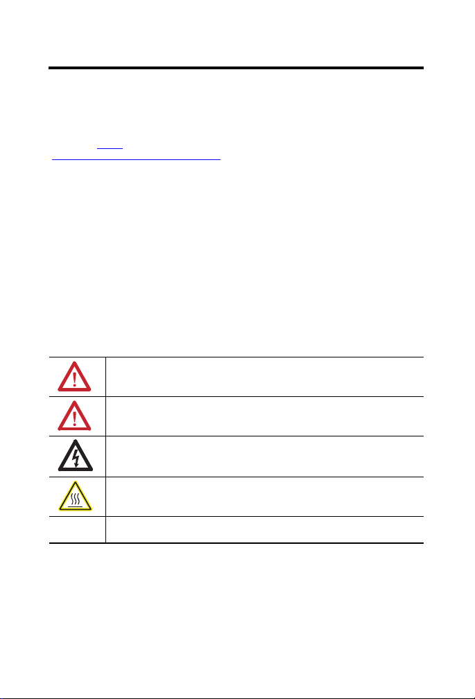
Throughout this manual, when necessary, we use notes to make you aware of safety considerations.
available from your local Rockwell Automation sales office or online at
WARNING: Identifies information about practices or circumstances that can cause an
explosion in a hazardous environment, which may lead to personal injury or death,
property damage, or economic loss.
ATTENTION: Identifies information about practices or circumstances that can lead to
personal injury or death, property damage, or economic loss. Attentions help you identify
a hazard, avoid a hazard and recognize the consequences.
SHOCK HAZARD: Labels may be on or inside the equipment, for example, drive or motor,
to alert people that dangerous voltage may be present.
) describes some important differences between
BURN HAZARD: Labels may be on or inside the equipment, for example, drive or motor,
to alert people that surfaces may reach dangerous temperatures.
IMPORTANT Identifies information that is critical for successful application and understanding of the
product.
Rockwell Automation Publication 1769-IN089A-EN-P - March 2011
Page 3
CompactLogix Analog Output Module 3
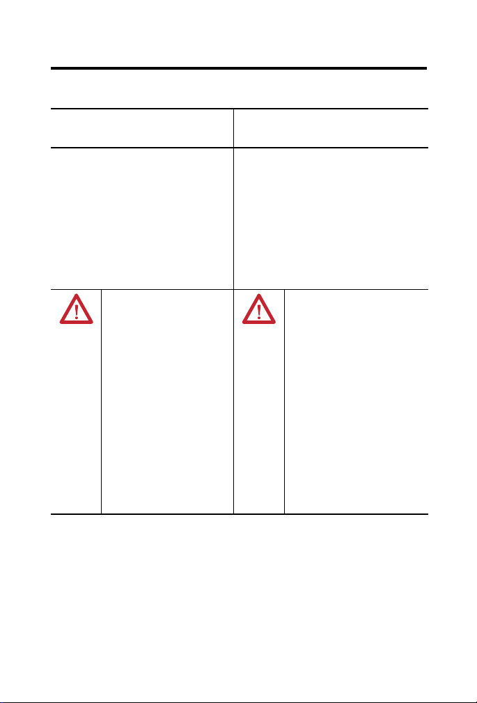
North American Hazardous Location Approval
The following information applies
when operating this equipment in
hazardous locations.
Products marked "CL I, DIV 2, GP A, B, C, D" are
suitable for use in Class I Division 2 Groups A, B, C,
D, Hazardous Locations and nonhazardous
locations only. Each product is supplied with
markings on the rating nameplate indicating the
hazardous location temperature code. When
combining products within a system, the most
adverse temperature code (lowest "T" number) may
be used to help determine the overall temperature
code of the system. Combinations of equipment in
your system are subject to investigation by the
local Authority Having Jurisdiction at the time of
installation.
WARNING:
Explosion Hazard -
•Do not disconnect equipment
unless power has been removed
or the area is known to be
nonhazardous.
•Do not disconnect connections to
this equipment unless power has
been removed or the area is
known to be nonhazardous.
Secure any external connections
that mate to this equipment by
using screws, sliding latches,
threaded connectors, or other
means provided with this product.
•Substitution of components may
impair suitability for Class I,
Division 2.
•If this product contains batteries,
they must only be changed in an
area known to be nonhazardous.
Informations sur l’utilisation de cet
équipement en environnements
dangereux.
Les produits marqués "CL I, DIV 2, GP A, B, C, D" ne
conviennent qu'à une utilisation en environnements
de Classe I Division 2 Groupes A, B, C, D dangereux et
non dangereux. Chaque produit est livré avec des
marquages sur sa plaque d'identification qui indiquent
le code de température pour les environnements
dangereux. Lorsque plusieurs produits sont combinés
dans un système, le code de température le plus
défavorable (code de température le plus faible) peut
être utilisé pour déterminer le code de température
global du système. Les combinaisons d'équipements
dans le système sont sujettes à inspection par les
autorités locales qualifiées au moment de
l'installation.
AVERTISSEMENT:
Risque d’Explosion –
•Couper le courant ou s'assurer que
l'environnement est classé non
dangereux avant de débrancher
l'équipement.
•Couper le courant ou s'assurer que
l'environnement est classé non
dangereux avant de débrancher les
connecteurs. Fixer tous les
connecteurs externes reliés à cet
équipement à l'aide de vis, loquets
coulissants, connecteurs filetés ou
autres moyens fournis avec ce
produit.
•La substitution de composants peut
rendre cet équipement inadapté à
une utilisation en environnement de
Classe I, Division 2.
•S'assurer que l'environnement est
classé non dangereux avant de
changer les piles.
Rockwell Automation Publication 1769-IN089A-EN-P - March 2011
Page 4

4 CompactLogix Analog Output Module
Environment and Enclosure
ATTENTION: This equipment is intended for use in a Pollution Degree 2
industrial environment, in overvoltage Category II applications (as defined
in IEC 60664-1), at altitudes up to 2000 m (6562 ft) without derating.
This equipment is considered Group 1, Class A industrial equipment according
to IEC/CISPR 11. Without appropriate precautions, there may be difficulties
with electromagnetic compatibility in residential and other environments due
to conducted and radiated disturbances.
This equipment is supplied as open-type equipment. It must be mounted within
an enclosure that is suitably designed for those specific environmental
conditions that will be present and appropriately designed to prevent personal
injury resulting from accessibility to live parts. The enclosure must have
suitable flame-retardant properties to prevent or minimize the spread of flame,
complying with a flame spread rating of 5VA, V2, V1, V0 (or equivalent) if
non-metallic. The interior of the enclosure must be accessible only by the use
of a tool. Subsequent sections of this publication may contain additional
information regarding specific enclosure type ratings that are required to
comply with certain product safety certifications.
Besides this publication, see:
• Industrial Automation Wiring and Grounding Guidelines, publication
• NEMA Standards publication 250 and IEC publication 60529, as applicable,
, for additional installation requirements.
1770-4.1
for explanations of the degrees of protection provided by different types of
enclosure.
Rockwell Automation Publication 1769-IN089A-EN-P - March 2011
Page 5
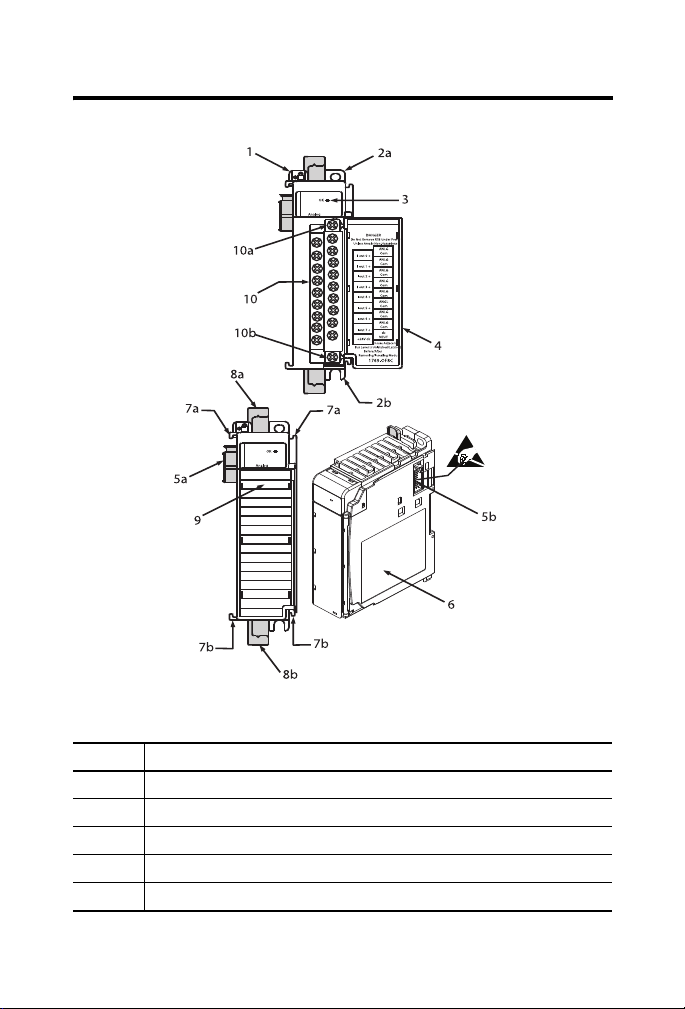
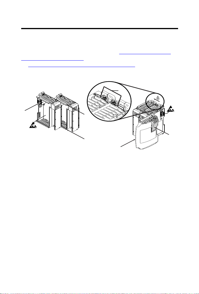
About the Module
CompactLogix Analog Output Module 5
Item Description
1 Bus lever (with locking function)
2a Upper panel mounting tab
2b Lower panel mounting tab
3 Module status indicator
4 Module door with terminal identification label
Rockwell Automation Publication 1769-IN089A-EN-P - March 2011
Page 6
6 CompactLogix Analog Output Module
Item Description
5a Movable bus connector with female pins
5b Stationary bus connector with male pins
6 Nameplate label
7a Upper tongue-and-groove slots
7b Lower tongue-and-groove slots
8a Upper DIN rail latch
8b Lower DIN rail latch
9 Write-on label (user ID tag)
10 Removable terminal block (RTB) with finger-safe cover
10a RTB upper retaining screw
10b RTB lower retaining screw
Prevent Electrostatic Discharge
ATTENTION: This equipment is sensitive to electrostatic discharge, which
can cause internal damage and affect normal operation. Follow these
guidelines when you handle this equipment:
• Touch a grounded object to discharge potential static.
• Wear an approved grounding wriststrap.
• Do not touch connectors or pins on component boards.
• Do not touch circuit components inside the equipment.
• Use a static-safe workstation, if available.
• Store the equipment in appropriate static-safe packaging when not in use.
Remove Power
WARNING: When you insert or remove the module while backplane
power is on, an electrical arc can occur. This could cause an explosion in
hazardous location installations.
Be sure that power is removed or the area is nonhazardous before proceeding.
Repeated electrical arcing causes excessive wear to contacts on both the
module and its mating connector. Worn contacts may create electrical
resistance that can affect module operation.
Rockwell Automation Publication 1769-IN089A-EN-P - March 2011
Page 7
CompactLogix Analog Output Module 7
6
5
4
3
1
1
2
Assembling the Module
The module can be attached to the controller or an adjacent I/O module before
or after mounting. For mounting instructions, see Panel Mounting on page 9, or
DIN Rail Mounting on page 10. To work with a system that is already mounted,
see Replacing a Single Module within a System
The following procedure shows you how to assemble the Compact I/O system.
1. Disconnect power.
2. Check that the bus lever of the module to be installed is in the unlocked
(fully right) position.
3. Use the upper and lower tongue-and-groove slots (1) to secure the
modules together (or to a controller).
4. Move the module back along the tongue-and-groove slots until the bus
connectors (2) line up with each other.
5. Push the bus lever back slightly to clear the positioning tab (3).
on page 10.
Use your fingers or a small screwdriver.
Rockwell Automation Publication 1769-IN089A-EN-P - March 2011
Page 8
8 CompactLogix Analog Output Module
IMPORTANT
Top
Bottom
Side Side
Host Controller
Compact I/O
Compact I/O
Compact I/O
Compact I/O
Compact I/O
End Cap
6. To allow communication between the controller and module, move the
bus lever fully to the left (4) until it clicks.
Be sure that it is locked firmly in place.
ATTENTION: When attaching I/O modules, it is very important that the
bus connectors are securely locked together to ensure proper electrical
connection.
7. Attach an end cap terminator (5) to the last module in the system by
using the tongue-and-groove slots as before.
8. Lock the end cap bus terminator (6).
A 1769-ECR or 1769-ECL right or left end cap must be used to terminate
the end of the serial communication bus.
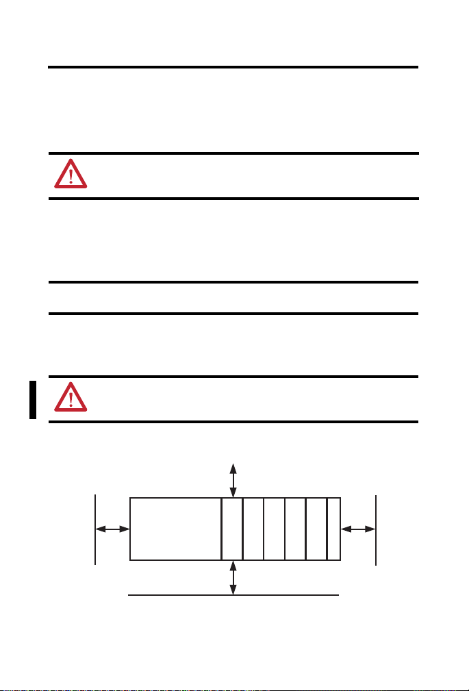
Mounting Expansion I/O
WARNING: When used in a Class I, Division 2, hazardous location, this
equipment must be mounted in a suitable enclosure with proper wiring
method that complies with the governing electrical codes.
Minimum Spacing
Rockwell Automation Publication 1769-IN089A-EN-P - March 2011
Page 9
CompactLogix Analog Output Module 9
Host
Compact I/O
Compact I/O
Compact I/O
End Cap
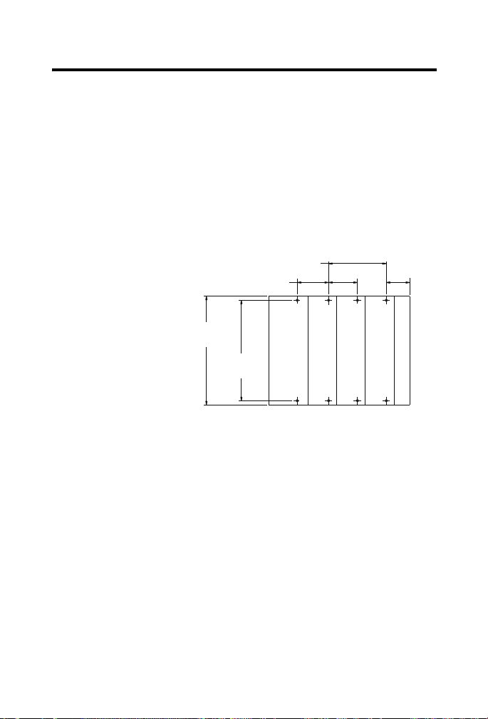
132 (5.197)
122.6±0.2
35
(1.38)
28.5
(1.12)
Refer to host controller documentation for this dimension.
For more than 2 modules: (number of modules-1) X 35mm (1.38 in.)
NOTE: All dimensions are in
mm (in.). Hole spacing
tolerance: ±0.4 mm (0.016 in.)
Maintain spacing from enclosure walls, wireways, and adjacent equipment.
Allow 50 mm (2 in.) of space on all sides for adequate ventilation, as shown.
Panel Mounting
Mount the module to a panel by using two screws per module. Use M4 or #8
panhead screws. Mounting screws are required on every module.
Panel Mounting Using the Dimensional Template
Panel Mounting Using Modules as a Template
The following procedure lets you use the assembled modules as a template for
drilling holes in the panel. If you have sophisticated panel mounting equipment,
you can use the dimensional template provided on page 9. Due to module
mounting hole tolerance, it is important to follow this procedure.
1. On a clean work surface, assemble no more than three modules.
2. Using the assembled modules as a template, carefully mark the center of
all module-mounting holes on the panel.
3. Return the assembled modules to the clean work surface, including any
previously mounted modules.
4. Drill and tap the mounting holes for the recommended M4 or #8 screw.
Rockwell Automation Publication 1769-IN089A-EN-P - March 2011
Page 10

10 CompactLogix Analog Output Module
TIP
5. Place the modules back on the panel, and check for proper hole
alignment.
6. Attach the modules to the panel by using the mounting screws.
If mounting more modules, mount only the last one of this group and put
the others aside. This reduces remounting time during drilling and
tapping of the next group.
7. Repeat steps 1
…6 for any remaining modules.
DIN Rail Mounting
ATTENTION: During panel or DIN rail mounting of all devices, be sure that
all debris (such as metal chips and wire strands is kept from falling into the
module. Debris that falls into the module could cause damage on power
up.
The module can be mounted using the following DIN rails: 35 x 7.5 mm (EN
50 022 - 35 x 7.5) or 35 x 15 mm (EN 50 022 - 35 x 15).
Before mounting the module on a DIN rail, close the DIN rail latches. Press
the DIN rail mounting area of the module against the DIN rail. The latches
will momentarily open and lock into place.
Replacing a Single Module within a System
The module can be replaced while the system is mounted to a panel (or DIN
rail). Follow the steps below:
1. Remove power.
See important note on page 6
2. On the module to be removed, remove the upper and lower mounting
screws from the module (or open the DIN latches using a flat-blade or
phillips-style screwdriver).
3. Move the bus lever to the right to disconnect (unlock) the bus.
.
Rockwell Automation Publication 1769-IN089A-EN-P - March 2011
Page 11

CompactLogix Analog Output Module 11
TIP
4. On the right-side adjacent module, move its bus lever to the right
(unlock) to disconnect it from the module to be removed.
5. Gently slide the disconnected module forward.
If you feel excessive resistance, check that the module has been
disconnected from the bus, and that both mounting screws have been
removed (or DIN latches opened).
It may be necessary to rock the module slightly from front to back to
remove it, or, in a panel-mounted system, to loosen the screws of
adjacent modules.
6. Before installing the replacement module, be sure that the bus lever on
the module to be installed, and on the right-side adjacent module are in
the unlocked (fully right) position.
7. Slide the replacement module into the open slot.
8. Connect the modules together by locking (fully left) the bus levers on
the replacement module and the right-side adjacent module.
9. Replace the mounting screws (or snap the module onto the DIN rail).
Module Spare/replacement Parts
• Terminal block, catalog number 1769-RTBN12 (1 per kit)
(A-B part number A22112-319-01)
• Door, catalog number 1769-RD (2 per kit)
Grounding the Module
ATTENTION: This product is intended to be mounted to a well-grounded
mounting surface such as a metal panel. Additional grounding connections
from the power supply's mounting tabs or DIN rail (if used) are not required
unless the mounting surface cannot be grounded. Refer to Industrial
Automation Wiring and Grounding Guidelines, Rockwell Automation
publication 1770-4.1
, for additional information.
Rockwell Automation Publication 1769-IN089A-EN-P - March 2011
Page 12

12 CompactLogix Analog Output Module
IMPORTANT
System Wiring Guidelines
WARNING: EXPLOSION HAZARD
All wiring must comply with N.E.C. article 501-4(b).
Consider the following when wiring your system:
• All module commons (ANLG COM) are connected in the analog
module. The analog common (ANLG COM) is not connected to earth
ground inside the module.
• Channels are not isolated from each other.
• Use Belden 8761, or equivalent, shielded wire.
• Under normal conditions, the drain wire and shield junction must be
connected to earth ground, via a panel or DIN rail mounting screw at
the analog I/O module end. Keep the shield connection to ground as
short as possible.
• To ensure optimum accuracy, limit overall cable impedance by keeping
your cable as short as possible. Locate the I/O system as close to your
sensors or actuators as your application will permit.
(1)
To comply with UL restrictions, this equipment must be powered from a
source compliant with Class 2 or Limited Voltage/Current.
(1) In environments where high frequency noise may be present, it may be necessary to ground the shield
Rockwell Automation Publication 1769-IN089A-EN-P - March 2011
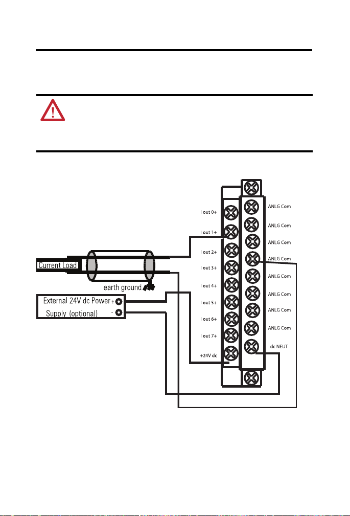
• Current outputs (Iout 0+ to Iout 7+) of the 1769-OF8C module source
current that returns to ANLG COM. Load resistance for a current
output channel must remain between 0…500 Ω.
• Voltage outputs (Vout 0+ to Vout 7+) of the 1769-OF8V module are
referenced to ANLG COM. Load resistance for a voltage output
channel must be equal to or greater than 1K W.
via a 0.1µF capacitor at the load end and also ground the module end without a capacitor.
Page 13

CompactLogix Analog Output Module 13
External Power Switch
Pressed on the top
Bus Power (default)
Pressed on the bottom
External Power
External Power Switch
The modules have an external 24V DC power switch that gives you the option
of using an external power supply. The switch is located in on the lower left
portion of the module’s circuit board, as shown below. With this switch pressed
on the top (default), 24V DC power is drawn from the 1769 system power
supply via the 1769 I/O bus. Pressed on the bottom, 24V DC power is drawn
from the external power supply.
Wire the external power supply to the module via the module’s terminal block.
The external power supply must be rated Class 2, with a 24V DC range of
20.4…26.4V DC and the following minimums:
• Volatge 135 mA
• Current 185mA
Rockwell Automation Publication 1769-IN089A-EN-P - March 2011
Page 14
14 CompactLogix Analog Output Module
Wiring Output Devices
Basic wiring of output devices is shown below.
ATTENTION: Miswiring of the module to an AC/DC source will damage
the module.
Be careful when stripping wires. Wire fragments that fall into a module could
cause damage at power up. Once wiring is complete, make sure the module is
free of all metal fragments.
• 1769-OF8C module:
Rockwell Automation Publication 1769-IN089A-EN-P - March 2011
Page 15

CompactLogix Analog Output Module 15
• 1769-OF8V module:
Labeling the Terminals
A removable, write-on label is provided with the module. Remove the label from
the door, mark the identification of each terminal with permanent ink, and slide
the label back into the door. Your markings (ID tag) will be visible when the
module door is closed.
Rockwell Automation Publication 1769-IN089A-EN-P - March 2011
Page 16

16 CompactLogix Analog Output Module
TIP
Wiring the finger-safe terminal block
Upper Retaining Screw
Lower Retaining Screw
Removing the Finger-Safe Terminal Block
WARNING: When you connect or disconnect the Removable Terminal
Block (RTB) with field side power applied, an electrical arc can occur. This
could cause an explosion in hazardous location installations.
Be sure that power is removed or the area is nonhazardous before proceeding.
To remove the terminal block, loosen the upper and lower retaining screws. The
terminal block will back away from the module as you remove the screws. When
replacing the terminal block, torque the retaining screws to 0.46 N•m
(4.1 lb•in).
Wiring the Finger-safe Terminal Block
When wiring the terminal block, keep the finger-safe cover in place.
1. Loosen the terminal screws to be wired.
2. Route the wire under the terminal pressure plate. You can use the bare
wire or a spade lug. The terminals will accept a 6.35 mm (0.25 in.) spade
lug.
Rockwell Automation Publication 1769-IN089A-EN-P - March 2011
The terminal screws are non-captive. Therefore, it is possible to use a
ring lug [maximum 1/4 inch o.d. with a 0.139 inch minimum i.d. (M3.5)]
with the module.
Page 17

CompactLogix Analog Output Module 17
TIP
IMPORTANT
3. Tighten the terminal screw making sure the pressure plate secures the
wire. Recommended torque when tightening terminal screws is 0.68
N•m (6 in•lb).
If you need to remove the finger-safe cover, insert a screw driver into one
of the square, wiring holes and gently pry the cover off. If you wire the
terminal block with the finger-safe cover removed, you will not be able to
put the cover back on the terminal block because the wires will obstruct
the cover.
Wire Size and Terminal Screw Torque
Each terminal accepts up to two wires with the following restrictions.
Wire Type Wire Size Terminal Screw
Solid Cu-90 °C (194 °F) #14…#22 AWG 0.68 N•m
Stranded Cu-90 °C (194 °F) #16…#22 AWG 0.68 N•m
Tor qu e
(6 lb•in)
(6 lb•in)
Retaining Screw
Tor qu e
0.46 N•m
(4.1 lb•in)
0.46 N•m
(4.1 lb•in)
I/O Memory Mapping
If you are using RSLogix 5000 software, version 15, please refer to
RSLogix 5000 Controller Tags
Output Data File
For each module, slot x, words 0…7 in the output data file contain the channel
0 …7 output data. Word 8 is used to unlatch any condition that has been latched.
Refer to the Compact I/O Analog Modules User Manual, publication
1769-UM002
Word
0 SGN Analog Output Data Channel 0
1 SGN Analog Output Data Channel 1
, for additional details.
1514131211109876543210
Rockwell Automation Publication 1769-IN089A-EN-P - March 2011
on page 22
Bit Position
Page 18

18 CompactLogix Analog Output Module
Bit Position
1514131211109876543210
Word
2 SGN Analog Output Data Channel 2
3 SGN Analog Output Data Channel 3
4 SGN Analog Output Data Channel 4
5 SGN Analog Output Data Channel 5
6 SGN Analog Output Data Channel 6
7 SGN Analog Output Data Channel 7
8 UU7 UO7 UU6 UO6 UU5 UO5 UU4 UO4 UU3 UO3 UU2 UO2 UU1 UO1 UU0 UO0
• SGN = Sign bit in two’s complement format.
• UU = Unlatch under-range (or low clamp exceeded) alarm.
• UO = Unlatch over-range (or high clamp exceeded) alarm.
Input Data File
For each module, slot x, input data file words 3…10 contain the state of the
module’s output data (output data echo) file words 0…7. During normal
operation, these input words represent the analog values that the outputs are
directed to by the control program.
Bit Position
151413121110987654321 0
Word
0 PFS7S6S5S4S3S2S1 S0
1 D3H3U3O3D2H2U2O2D1H1U1O1D0H0U0 O0
2 D7H7U7O7D6H6U6O6D5H5U5O5D4H4U4 O4
3 Channel 0 Data Value
4 Channel 1 Data Value
5 Channel 2 Data Value
6 Channel 3 Data Value
7 Channel 4 Data Value
8 Channel 5 Data Value
9 Channel 6 Data Value
10 Channel 7 Data Value
Rockwell Automation Publication 1769-IN089A-EN-P - March 2011
Page 19

CompactLogix Analog Output Module 19
IMPORTANT
• PF = Analog power fail.
• S = General status (over-range, under-range, or open-circuit).
• D = Open-circuit diagnostics.
• H = Output held bit.
• U = Under-range (or low-clamp exceeded) alarm.
• O = Over-range (or high-clamp exceeded) alarm
The output module’s input data file reflects the analog output data echo
of the module, not necessarily the electrical state of the output terminals.
It does not reflect shorted or open outputs.
Configuration Data File
The manipulation of the bits from this file is normally done with programming
software, such as RSLogix 500, RSNetWorx for DeviceNet software, during
initial configuration of the system. In that case, graphical screens are provided by
the programmer to simplify configuration. However, some devices, like the
1769-ADN DeviceNet adapter, also allow the bits to be altered as part of the
control program, using communication rungs. In that case, it is necessary to
understand the bit arrangement. The channel configuration words, the first two
words of each eight word group, are described on page 21
CompactLogix I/O Analog Modules User Manual, publication 1769-UM002,
for additional details.
. Refer to the
Word Description Word Description
0 Channel 0 Configuration Word 0 24 Channel 3 Configuration Word 0
1 Channel 0 Configuration Word 1 25 Channel 3 Configuration Word 1
2 Channel 0 Fault Value Word 26 Channel 3 Fault Value Word
3 Channel 0 Program Idle Mode Word 27 Channel 3 Program Idle Mode Word
4 Channel 0 Low Clamp 28 Channel 3 Low Clamp
5 Channel 0 High Clamp 29 Channel 3 High Clamp
6 Channel 0 Ramp Rate 30 Channel 3 Ramp Rate
Rockwell Automation Publication 1769-IN089A-EN-P - March 2011
Page 20

20 CompactLogix Analog Output Module
Word Description Word Description
7 Channel 0 Spare 31 Channel 3 Spare
8 Channel 1 Configuration Word 0 32 Channel 4 Configuration Word 0
9 Channel 1 Configuration Word 1 33 Channel 4 Configuration Word 1
10 Channel 1 Fault Value Word 34 Channel 4 Fault Value Word
11 Channel 1 Program Idle Mode Word 35 Channel 4 Program Idle Mode Word
12 Channel 1 Low Clamp 36 Channel 4 Low Clamp
13 Channel 1 High Clamp 37 Channel 4 High Clamp
14 Channel 1 Ramp Rate 38 Channel 4 Ramp Rate
15 Channel 1 Spare 39 Channel 4 Spare
16 Channel 2 Configuration Word 0 40 Channel 5 Configuration Word 0
17 Channel 2 Configuration Word 1 41 Channel 5 Configuration Word 1
18 Channel 2 Fault Value Word 42 Channel 5 Fault Value Word
19 Channel 2 Program Idle Mode Word 43 Channel 5 Program Idle Mode Word
20 Channel 2 Low Clamp 44 Channel 5 Low Clamp
21 Channel 2 High Clamp 45 Channel 5 High Clamp
22 Channel 2 Ramp Rate 46 Channel 5 Ramp Rate
23 Channel 2 Spare 47 Channel 5 Spare
Word Description Word Description
48 Channel 6 Configuration Word 0 56 Channel 7 Configuration Word 0
49 Channel 6 Configuration Word 1 57 Channel 7 Configuration Word 1
50 Channel 6 Fault Value Word 58 Channel 7 Fault Value Word
51 Channel 6 Program Idle Mode Word 59 Channel 7 Program Idle Mode Word
52 Channel 6 Low Clamp 60 Channel 7 Low Clamp
53 Channel 6 High Clamp 61 Channel 7 High Clamp
54 Channel 6 Ramp Rate 62 Channel 7 Ramp Rate
55 Channel 6 Spare 63 Channel 7 Spare
Rockwell Automation Publication 1769-IN089A-EN-P - March 2011
Page 21

CompactLogix Analog Output Module 21
Word/Bit 15 14 13 12 11 10 9 8 7 6 5 4 3 2 1 0
Word 0 E Reserved SIU SIO LA ER FM PM HI PFE
Word 1 Reserved Output Data
Format Select
Reserved Output
Type/Range
• E = Channel Enable: (0 = Disabled, 1 = output 0 and hold Enabled,
process changes)
• Reserved = Set to zero
• SIU = System interrupt low clamp, under-range alarms: (0 = Disabled, 1
= Enabled)
• SIO = System interrupt high clamp, over-range alarms: (0 = Disabled, 1
= Enabled)
• LA = Latch low/high clamp, under/over-range alarms: (0 = Disabled, 1
= Enabled)
• ER = Enable r amping : (0 = Disa bled, 1 = Enabled. Ramp rate limit ed by
fault states.)
• FM = Fault mode: (0 = Hold Last State, 1 = User Defined Value)
• PM = Program mode: (0 = Hold Last State, 1 = User Defined Value)
• HI = Hold for initialization: (0 = Disabled, 1 = Enabled)
• PFE = Program/idle to fault enable: (0 = Disabled, 1 = Enabled)
Channel Configuration Words
The first two words of each eight-word group in the configuration file let you
change the parameters of each channel independently. For example, words 8 and
9 correspond to channel 1 while words 56 and 57 correspond to channel 7.
Define Indicate this These bit settings
Program (idle)
to Fault Enable
Hold for
Initialization
Program (Idle)
Mode Data
(1)
Applied
Fault Mode Data
(1)
Applied
Disabled 0 0 0 0 0 0 0 0 0
Enabled 0 0 0 0 0 0 0 0 1
1514131211109876543210
0 0 0 0 0 0 0 0 0
0 0 0 0 0 0 0 0 1
Rockwell Automation Publication 1769-IN089A-EN-P - March 2011
Page 22

22 CompactLogix Analog Output Module
Define Indicate this These bit settings
Program (Idle)
Mode
Fault Mode Hold Last State
Enable
Ramping
System
Interrupt High
Clamp
System
Interrupt Low
Clamp
Enable
Channel
(1) These functions are not suppo rted by all controllers (for example, MicroLogix 1500) using any configuration method.
Output Range
Select
Output Data
Select
Hold Last State
User-Defined
(1)
Value
User-Defined Fault
(1)
Value
Disabled 0 0 0 0 0 0 0 0 0
Enabled 0 0 0 0 0 0 0 0 1
Disabled 0 0 0 0 0 0 0 0 0
Enabled 0 0 0 0 0 0 0 0 1
Disabled 0 0 0 0 0 0 0 00
Enabled 0 0 0 0 0 0 0 01
Disabled 0 0 0 0 0 0 0 0 0
Enabled 1 0 0 0 0 0 0 0 0
Refer to your controller manual for details.
Define Indicate this These bit settings
0 to 20 mA DC 00000 00000000
4 to 20 mA DC 00000 00000001
Raw/proportional
Counts
Engineering Units0000000100000
Scaled for PID 0000001000000
Percent Range 0000001100000
15141312111098765432 10
(1)
0 0 0 0 0 0 0 0 0
0 0 0 0 0 0 0 0 1
(1)
0 0 0 0 0 0 0 0 0
0 0 0 0 0 0 0 0 1
1514131211109876543210
0000000000000
RSLogix 5000 Controller Tags
Use the following controller tags with RSLogix 5000 software, version 15 and
later.
Rockwell Automation Publication 1769-IN089A-EN-P - March 2011
Page 23

CompactLogix Analog Output Module 23
Channel 0 and 1 Configuration Data
The following table lists channel 0 and 1 configuration data. The same
information applies to all channels.
- Local:1:C AB:1769_OF8C:C:0
Local:1:C.Ch0ProgToFaultEn BOOL Decimal
Local:1:C.Ch0HoldForInit BOOL Decimal
Local:1:C.Ch0ProgMode BOOL Decimal
Local:1:C.Ch0FaultMode BOOL Decimal
Local:1:C.Ch0RampEn BOOL Decimal
Local:1:C.Ch0AlarmLatchEn BOOL Decimal
Local:1:C.Ch0OverRangeInterruptEn BOOL Decimal
Local:1:C.Ch0UnderRangeInterruptEn BOOL Decimal
Local:1:C.Ch0En BOOL Decimal
+ Local:1:C.Ch0Range SINT Decimal
+ Local:1:C.Ch0Da taFormat SINT Decimal
+ Local:1:C.Ch0FaultValue INT Decimal
+ Local:1:C.Ch0Prog Value INT Decimal
+ Local:1:C.Ch0LClampValue INT De cimal
+ Local:1:C.Ch0HCl ampValue INT Decimal
+ Local:1:C.Ch0RampRate INT Decimal
Local:1:C.Ch1ProgToFaultEn BOOL Decimal
Local:1:C.Ch1HoldForInit BOOL Decimal
Local:1:C.Ch1ProgMode BOOL Decimal
Local:1:C.Ch1FaultMode BOOL Decimal
Local:1:C.Ch1RampEn BOOL Decimal
Local:1:C.Ch1AlarmLatchEn BOOL Decimal
Local:1:C.Ch1OverRangeInterruptEn BOOL Decimal
Local:1:C.Ch1UnderRangeInterruptEn BOOL Decimal
Rockwell Automation Publication 1769-IN089A-EN-P - March 2011
Page 24

24 CompactLogix Analog Output Module
Local:1:C.Ch1En BOOL Decimal
+ Local:1:C.Ch1Ra nge SINT Decimal
+ Local:1:C.C h1DataFormat SINT Decimal
+ Local:1:C.Ch1Fa ultVa lue INT Decimal
+ Local:1:C.C h1ProgValue INT Decimal
+ Local:1:C.Ch1LCla mpValue INT Decimal
+ Local:1:C.Ch1HCla mpValue INT D ecimal
+ Local:1:C.Ch1Ra mpRate INT Decimal
Tag Name To Select Make These Bit Settings
(1)
15-876543210
Ch#ProgToFaultEn Enable 1
Disable 0
Ch#HoldForInit Enable 1
Disable 0
Ch#ProgMode Enable 1
Disable 0
Ch#FaultMode Enable 1
Disable 0
Ch#RampEn Enable 1
Disable 0
Ch#AlarmLatchEn Enable 1
Disable 0
Ch#OverRangeInterruptEn Enable 1
Disable 0
Ch#UnderRangeInterruptEn Enable 1
Disable 0
Ch#En Enable 1
Disable 0
Ch#Range (1769-OF8C) 0…20 mA DC 0
4…20 mA DC 1
Ch#Range (1769-OF8V) -10…+10V dc
0…5V dc
0…10V dc
1…5V dc
00
01
10
11
Rockwell Automation Publication 1769-IN089A-EN-P - March 2011
Page 25

CompactLogix Analog Output Module 25
Tag Name To Select Make These Bit Settings
15-876543210
Ch#DataFormat Raw/proportional
counts
Engineering units 0 1
Scaled for PID 1 0
Percent range 1 1
(1) All bit positions left blank in table must be set to 0.
Input Data
1769-OF8C Input Data
Ch3
Status
Ch0
OpenWire
Ch2
OpenWire
Ch4
OpenWire
Ch6
OpenWire
(1)
Tag
Name
Combined
Status
Module
Status
Ch0_1
Status
Ch2_3
Status
Ch4_5
Status
Ch6_7
Status
(1) Bit positions left blank in table are always set to 0.
76543210
Ch7
Status
Ch1
OpenWire
Ch3
OpenWire
Ch5
OpenWire
Ch7
OpenWire
Ch6
Status
Ch1
InHold
Ch3
InHold
Ch5
InHold
Ch7
InHold
Ch5
Status
Ch1
Under
Range
Ch3
Under
Range
Ch5
Under
Range
Ch7
Under
Range
Bit Indicates This
Ch4
Status
Ch1
Over
Range
Ch3
Over
Range
Ch5
Over
Range
Ch7
Over
Range
Ch2
Status
Ch0
InHold
Ch2
InHold
Ch4
InHold
Ch6
InHold
Ch1
Status
Ch0
Under
Range
Ch2
Under
Range
Ch4
Under
Range
Ch6
Under
Range
(1)
00
Ch0
Status
Power
Fail
Ch0
Over
Range
Ch2
Over
Range
Ch4
Over
Range
Ch6
Over
Range
Rockwell Automation Publication 1769-IN089A-EN-P - March 2011
Page 26

26 CompactLogix Analog Output Module
1769-OF8C Input Data
- Local:1:I AB:1769_OF8C:I:0
+ Local:1:I.Fault DINT Binary
+ Local:1:I.Combined Status SINT Binary
Local:1:I.Ch0Status BOOL Decimal
Local:1:I.Ch1Status BOOL Decimal
Local:1:I.Ch2Status BOOL Decimal
Local:1:I.Ch3Status BOOL Decimal
Local:1:I.Ch4Status BOOL Decimal
Local:1:I.Ch5Status BOOL Decimal
Local:1:I.Ch6Status BOOL Decimal
Local:1:I.Ch7Status BOOL Decimal
+ Local:1:I.ModuleStatus SINT Binary
Local:1:I.PowerFail BOOL Decimal
+ Local:1:I.Ch0_1St atus SINT Binary
Local:1:I.Ch0OverRange BOOL Decimal
Local:1:I.Ch0UnderRange BOOL Decimal
Local:1:I.Ch0InHold BOOL Decimal
Local:1:I.Ch0OpenWire BOOL Decimal
Local:1:I.Ch1OverRange BOOL Decimal
Local:1:I.Ch1UnderRange BOOL Decimal
Local:1:I.Ch1InHold BOOL Decimal
Local:1:I.Ch1OpenWire BOOL Decimal
+ Local:1:I.Ch2_3St atus SINT Binary
Local:1:I.Ch2OverRange BOOL Decimal
Local:1:I.Ch2UnderRange BOOL Decimal
Local:1:I.Ch2InHold BOOL Decimal
Local:1:I.Ch2OpenWire BOOL Decimal
Local:1:I.Ch3OverRange BOOL Decimal
Local:1:I.Ch3UnderRange BOOL Decimal
Rockwell Automation Publication 1769-IN089A-EN-P - March 2011
Page 27

CompactLogix Analog Output Module 27
1769-OF8C Input Data
Local:1:I.Ch3InHold BOOL Decimal
Local:1:I.Ch3OpenWire BOOL Decimal
+ Local:1:I.Ch4_5Status SINT Binary
Local:1:I.Ch4OverRange BOOL Decimal
Local:1:I.Ch4UnderRange BOOL Decimal
Local:1:I.Ch4InHold BOOL Decimal
Local:1:I.Ch4OpenWire BOOL Decimal
Local:1:I.Ch5OverRange BOOL Decimal
Local:1:I.Ch5UnderRange BOOL Decimal
Local:1:I.Ch5InHold BOOL Decimal
Local:1:I.Ch5OpenWire BOOL Decimal
+ Local:1:I.Ch6_7Status SINT Binary
Local:1:I.Ch6OverRange BOOL Decimal
Local:1:I.Ch6UnderRange BOOL Decimal
Local:1:I.Ch6InHold BOOL Decimal
Local:1:I.Ch6OpenWire BOOL Decimal
Local:1:I.Ch7OverRange BOOL Decimal
Local:1:I.Ch7UnderRange BOOL Decimal
Local:1:I.Ch7InHold BOOL Decimal
Local:1:I.Ch7OpenWire BOOL Decimal
+ Local:1:I.Ch0ReadBa ck INT Decimal
+ Local:1:I.Ch1ReadBa ck INT Decimal
+ Local:1:I.Ch2ReadBa ck INT Decimal
+ Local:1:I.Ch3ReadBa ck INT Decimal
+ Local:1:I.Ch4ReadBa ck INT Decimal
+ Local:1:I.Ch5ReadBa ck INT Decimal
+ Local:1:I.Ch6ReadBa ck INT Decimal
+ Local:1:I.Ch7ReadBa ck INT Decimal
Rockwell Automation Publication 1769-IN089A-EN-P - March 2011
Page 28

28 CompactLogix Analog Output Module
1769-OF8V Input Data
Ch6
Status
Ch1
InHold
Ch3
InHold
Ch5
InHold
Ch7
InHold
(1)
Ch5
Ch4
Status
Status
Ch1
Ch1
Under
Over
Range
Range
Ch3
Ch3
Under
Over
Range
Range
Ch5
Ch5
Under
Over
Range
Range
Ch7
Ch7
Under
Over
Range
Range
Tag
Name
Combined
Status
Module
Status
Ch0_1
Status
Ch2_3
Status
Ch4_5
Status
Ch6_7
Status
(1) Bit positions left bla nk in table are always set to 0.
Bit Indicates This
7 654 3 210
Ch7
Status
Ch3
Status
Ch2
Status
Ch0
InHold
Ch2
InHold
Ch4
InHold
Ch6
InHold
Ch1
Status
Ch0
Under
Range
Ch2
Under
Range
Ch4
Under
Range
Ch6
Under
Range
Ch0
Status
Power
Fail
Ch0
Over
Range
Ch2
Over
Range
Ch4
Over
Range
Ch6
Over
Range
Rockwell Automation Publication 1769-IN089A-EN-P - March 2011
Page 29

CompactLogix Analog Output Module 29
1769-OF8V Input Data
- Local:1:I AB:1769_OF8V:I:0
+ Local:1:I.Fault DINT Binary
+ Local:1:I.CombinedStatus SINT Binary
Local:1:I.Ch0Status BOOL Decimal
Local:1:I.Ch1Status BOOL Decimal
Local:1:I.Ch2Status BOOL Decimal
Local:1:I.Ch3Status BOOL Decimal
Local:1:I.Ch4Status BOOL Decimal
Local:1:I.Ch5Status BOOL Decimal
Local:1:I.Ch6Status BOOL Decimal
Local:1:I.Ch7Status BOOL Decimal
+ Local:1:I.ModuleStatus SINT Binary
Local:1:I.PowerFail BOOL Decimal
+ Local:1:I.Ch0_1Status SINT Binary
Local:1:I.Ch0OverRange BOOL Decimal
Local:1:I.Ch0UnderRange BOOL Decimal
Local:1:I.Ch0InHold BOOL Decimal
Local:1:I.Ch1OverRange BOOL Decimal
Local:1:I.Ch1UnderRange BOOL Decimal
Local:1:I.Ch1InHold BOOL Decimal
+ Local:1:I.Ch2_3Status SINT Binary
Local:1:I.Ch2OverRange BOOL Decimal
Local:1:I.Ch2UnderRange BOOL Decimal
Local:1:I.Ch2InHold BOOL Decimal
Local:1:I.Ch3OverRange BOOL Decimal
Local:1:I.Ch3UnderRange BOOL Decimal
Local:1:I.Ch3InHold BOOL Decimal
Rockwell Automation Publication 1769-IN089A-EN-P - March 2011
Page 30

30 CompactLogix Analog Output Module
1769-OF8V Input Data
+ Local:1:I.Ch4_5St atus SINT Binary
Local:1:I.Ch4OverRange BOOL Decimal
Local:1:I.Ch4UnderRange BOOL Decimal
Local:1:I.Ch4InHold BOOL Decimal
Local:1:I.Ch5OverRange BOOL Decimal
Local:1:I.Ch5UnderRange BOOL Decimal
Local:1:I.Ch5InHold BOOL Decimal
+ Local:1:I.Ch6_7St atus SINT Binary
Local:1:I.Ch6OverRange BOOL Decimal
Local:1:I.Ch6UnderRange BOOL Decimal
Local:1:I.Ch6InHold BOOL Decimal
Local:1:I.Ch7OverRange BOOL Decimal
Local:1:I.Ch7UnderRange BOOL Decimal
Local:1:I.Ch7InHold BOOL Decimal
+ Local:1:I.Ch0Read Back INT Decimal
+ Local:1:I.Ch1Read Back INT Decimal
+ Local:1:I.Ch2Read Back INT Decimal
+ Local:1:I.Ch3Read Back INT Decimal
+ Local:1:I.Ch4Read Back INT Decimal
+ Local:1:I.Ch5Read Back INT Decimal
+ Local:1:I.Ch6Read Back INT Decimal
+ Local:1:I.Ch7Read Back INT Decimal
Rockwell Automation Publication 1769-IN089A-EN-P - March 2011
Page 31

CompactLogix Analog Output Module 31
Output Data
1769-OF8C and 1769-OF8V Output Data
Local:1:O AB:1769_OF8C:O:0 / AB:1769_OF8V:O:0
+ Local:1:O.Ch0Data INT Decimal
+ Local:1:O.Ch1Data INT Decimal
+ Local:1:O.Ch2Data INT Decimal
+ Local:1:O.Ch3Data INT Decimal
+ Local:1:O.Ch4Data INT Decimal
+ Local:1:O.Ch5Data INT Decimal
+ Local:1:O.Ch6Data INT Decimal
+ Local:1:O.Ch7Data INT Decimal
+ Local:1:O.AlarmU nlatch INT Binary
Local:1:O.Ch0OverRangeUnlatch BOOL Decimal
Local:1:O.Ch0UnderRangeUnlatch BOOL Decima l
Local:1:O.Ch1OverRangeUnlatch BOOL Decimal
Local:1:O.Ch1UnderRangeUnlatch BOOL Decima l
Local:1:O.Ch2OverRangeUnlatch BOOL Decimal
Local:1:O.Ch2UnderRangeUnlatch BOOL Decima l
Local:1:O.Ch3OverRangeUnlatch BOOL Decimal
Local:1:O.Ch3UnderRangeUnlatch BOOL Decima l
Local:1:O.Ch4OverRangeUnlatch BOOL Decimal
Local:1:O.Ch4UnderRangeUnlatch BOOL Decima l
Local:1:O.Ch5OverRangeUnlatch BOOL Decimal
Local:1:O.Ch5UnderRangeUnlatch BOOL Decima l
Local:1:O.Ch6OverRangeUnlatch BOOL Decimal
Local:1:O.Ch6UnderRangeUnlatch BOOL Decima l
Local:1:O.Ch7OverRangeUnlatch BOOL Decimal
Local:1:O.Ch7UnderRangeUnlatch BOOL Decima l
Rockwell Automation Publication 1769-IN089A-EN-P - March 2011
Page 32

32 CompactLogix Analog Output Module
Specifications
General Specifications 1769-OF8C and 1768-OF8V
Attribute 1769-OF8C and 1768-OF8V
Dimensions, HxWxD (approx.) 118 mm x 35 mm x 87 mm
Approximate Shipping Weight
(with carton)
Enclosure type rating None (open-style)
Wire Size 0.32…2.1 mm
Wiring Category
(1) Use this Conductor Category information for planning conductor routing. Refer to Industrial
Automation Wiring and Grounding Guidelines, publication 1770-4.1
Environmental Specifications 1769-OF8C and 1769-OF8V
Attribute 1769-OF8C and 1769-OF8V
Temperature, storage -40…85 °C (-40…185 °F)
Temperature, operating
• IEC 60068-2-1 (Test Ad,
• IEC 60068-2-2 (Test Bd,
• IEC 60068-2-14 (Test Nb,
Temperature, surrounding air, max 60 °C (140 °F)
Temperature, nonoperating
• IEC 60068-2-1 (Test Ab,
• IEC 60068-2-2 (Test Bb,
• IEC 60068-2-14 (Test Na,
North American temp code T4A
Vibration
IEC 60068-2-6 (Test Fc, Operating)
(1)
Operating Cold)
Operating Dry Heat)
Operating Thermal Shock)
Unpackaged Nonoperating Cold)
Unpackaged Nonoperating Dry
Heat)
Unpackaged Nonoperating
Thermal Shock)
Height including mounting tabs is 138 mm
4.65 in. x 1.38 in. x 3.43 in.
Height including mounting tabs is 5.43 in.
281g (0.62 lb.)
2
(22…14 AWG) solid copper wire or 0.32…1.3
2
(22…16 AWG) stranded copper wire rated at 90 °C
mm
(194 °F) insulation max
2 - on signal ports
.
0…60 °C (32…140 °F)
-40…85 °C (-40…185 °F)
5 g @ 10…500 Hz
Rockwell Automation Publication 1769-IN089A-EN-P - March 2011
Page 33

CompactLogix Analog Output Module 33
Environmental Specifications 1769-OF8C and 1769-OF8V
Attribute 1769-OF8C and 1769-OF8V
Shock, operating
IEC 60068-2-27 (Test Ea, Unpackaged
Shock)
Shock, nonoperating
IEC 60068-2-27 (Test Ea, Unpackaged
Shock)
Relative humidity
IEC 60068-2-30 (Test Db, Unpackaged
Damp Heat)
Emissions CISPR 11:
ESD immunity
IEC 61000-4-2
Radiated RF immunity
IEC 61000-4-3
EFT/B immunity
IEC 61000-4-4
Surge Transient Immunity
IEC 61000-4-5
Conducted RF immunity IEC 61000-4-6:
Supply power and current ratings Backplane (1769-OF8C):
20 g
30 g
5…95% noncondensing
Group 1, Class A
4 kV contact discharges
8 kV air discharges
10V/m with 1 kHz sine-wave 80% AM from 80…2000 MHz
10V/m with 200 Hz 50% Pulse 100% AM at 900 MHz
10V/m with 200 Hz 50% Pulse 100% AM at 1890 MHz
3V/m with 1 kHz sine-wave 80% AM from 2000…2700 MHz
±2 kV at 5 kHz on signal ports
±1 kV line-earth(CM) on shielded ports
10V rms with 1 kHz sine-wave 80% AM from 150 kHz…80
MHz
• 5V DC, 145mA
• 24V DC, 185 mA
Backplane (1769-OF8V):
• 5V DC, 145mA
• 24V DC, 135 mA
Field (1769-OF8C):
• 0…20 mA
• 4…20 mA
Field (1769-OF8V):
• -10V to… +10V, 0…+5V, 0…+10V, 1 to… +5V
Isolation voltage 30V (continuous), Reinforced Insulation Type, channel to
system and channel to channel.
Type tested at 710V DC for 60 s
Rockwell Automation Publication 1769-IN089A-EN-P - March 2011
Page 34

34 CompactLogix Analog Output Module
Output Specifications 1769-OF8C and 1769-OF8V
Attribute 1769-OF8C and 1769-OF8V
Analog normal operating ranges
Full Scale analog ranges
Number of outputs 8 single-ended
Bus current draw, max (1769-OF8C) 145 mA at 5V DC
Bus current draw, max (1769-OF8V) 145 mA at 5V DC
Heat dissipation (1769-OF8C): 2.69 total W (all points - 21 mA into 250 Ω - worst
Digital resolution across full range (1769-OF8C): 16 bits (unipolar)
Conversion rate (all channels) max. 5 ms
Step response to 63%
Resistive load on current output
(1769-OF8C)
Max inductive load (1769-OF8C) 0.1 mH
Load range output (1769-OF8V) > 1 kΩ at 10V DC
Max capacitive load (1769-OF8V) 1 µF
Field calibration None required
Overall accuracy
(4)
Accuracy drift with temperature (1769-OF8C): ±0.0058% FS per °C
Output ripple
range 0…50 kHz
(referred to output range)
(5)
(1)
(1769-OF8C): 0…20 mA, 4…20 mA
(1769-OF8V): ± 10V dc, 0…10V DC, 0…5V DC, 1…5V DC
(1)
(1769-OF8C): 0…21 mA, 3.2 to 21 mA
(1769-OF8V): ± 10.5V dc, -0.5…10.5V DC, -0.5…5.25V DC,
0.5…5.25V DC
185 mA at 24V DC
(2)
135 mA at 24V DC
case calculated)
(1769-OF8V): 2.16 total W (all points - 10.5V into 1 kΩ - worst
case calculated)
4…20 mA: 15.59 bits, 0.323 µA/bit
0…20 mA: 15.91 bits, 0.323 µA/bit
(1769-OF8V): 16 bits plus sign (bipolar)
±10V dc: 15.89 bits, 330 ?V/bit
0 to +5V dc: 13.89 bits, 330 µV/bit
0 to +10V dc: 14.89 bits, 330 µV/bit
+1 to +5V dc: 13.57 bits, 330 µV/bi
(3)
<2.9 ms
0…500 Ω (includes wire resistance)
(1769-OF8C): ±0.35% full scale at 25 °C (77 °F)
(1769-OF8V): ±0.5% full scale at 25 °C
(1769-OF8V): ±0.0086% FS per °C
±0.05%
Rockwell Automation Publication 1769-IN089A-EN-P - March 2011
Page 35

CompactLogix Analog Output Module 35
Output Specifications 1769-OF8C and 1769-OF8V
Attribute 1769-OF8C and 1769-OF8V
Non-linearity (in percent full scale) ±0.05%
Repeatability
(in percent full scale)
Output error over full temperature
Range
(0…60 °C [+32…+140 °F])
Output offset error
(0…60 °C [+32…+140 °F])
Output impedance (1769-OF8C): >1 MΩ
Open and short-circuit protection Yes
Maximum short-circuit current (1769-OF8C): 21 mA
Output overvoltage protection Yes
Time to detect open wire condition
(1769-OF8C)
Output response at system power up
and power down
Rated working voltage
Module OK status indicator On: module has power, has passed internal diagnostics, and is
Output group to bus isolation
(1769-OF8V)
Channel diagnostics Over- or under-range by bit reporting
System power supply distance rating The module may not be more than 8 modules away from the
Optional 24V DC Class 2 power supply
voltage range
Recommended cable Belden 8761 (shielded)
Vendor I.D. code 1
Product type code 10
Product code (1769-OF8C): 40
Input words 11
(6)
±0.05%
(1769-OF8C) Current: ±0.55%
(1769-OF8V) Current:±0.80%
±0.05%
(1769-OF8V): <1 Ω
(1769-OF8V): 30 mA
5 ms
±0.5V DC spike for < 5 ms
(7)
30V AC/30V DC
communicating over the bus
Flashing: external power failure
Off: Any of the above is not true
500V AC or 710V DC for 1 minute (qualification test)
30V AC/30V DC working voltage (IEC)
output wire broken or load resistance high by bit reporting
system power supply.
(8)
20.4 V…26.4 V DC
(1769-OF8V): 39
Rockwell Automation Publication 1769-IN089A-EN-P - March 2011
Page 36

36 CompactLogix Analog Output Module
Output Specifications 1769-OF8C and 1769-OF8V
Attribute 1769-OF8C and 1769-OF8V
Output words 9
Configuration words 64
(1) The over- or under-range flag will come on when the normal operating range (over/under) is exceeded.
The module will continue to convert the analog input up to the maximum full scale range. The flag
automatically resets when within the normal operating range unless configured to latch.
(2) If the optional 24V DC Class 2 power supply is used, the 24V DC current draw from the bus is 0 mA.
(3) Step response is the period of time between when the D/A converter was instructed to go from
minimum to full range until the device is at 63% of full range.
(4) Includes offset, gain, drift, non-linearity and repeatability error terms.
(5) Output ripple is the amount a fixed output varies with time, assuming a constant load and
temperature.
(6) Repeatability is the ability of the output module to reproduce output readings when the same
controller value is applied to it consecutively, under the same conditions and in the same direction.
(7) Rated working voltage is the maximum continuous voltage that can be applied at the input terminal,
including the input signal and the value that floats above ground potential (for example, 10V DC input
signal and 20V DC potential above ground).
(8) Failure to use a Class 2 power supply without regulation within these limits could result in improper
module operation.
Rockwell Automation Publication 1769-IN089A-EN-P - March 2011
Page 37

CompactLogix Analog Output Module 37
Certifications
Certifications
(when product is marked)
c-UL-us UL Listed for Class I, Division 2 Group A,B,C,D Hazardous
CE European Union 2004/108/EC EMC Directive, compliant with:
C-Tick Australian Radiocommunications Act, compliant with:
(1) See the Product Certification link at http//:www.ab.com
(1)
and other certification details.
1769-OF8C and 1769-OF8V
Locations, certified for U.S. and Canada. See UL File E10314.
• EN 61000-6-2; Industrial Immunity
• EN 61000-6-4; Industrial Emissions
• EN 61131-2; Programmable Controllers (Clause 8, Zone
A & B)
AS/NZS CISPR 11; Industrial Emissions
for Declarations of Conformity, Certificates,
Rockwell Automation Publication 1769-IN089A-EN-P - March 2011
Page 38

38 CompactLogix Analog Output Module
Additional Resources
These documents contain additional information concerning related Rockwell
Automation products.
Resource Description
1769-L32E and 1769-L35E CompactLogix
Controller Installation Instructions, publication
1769-IN020
1769-SDN Compact I/O DeviceNet Scanner
Module Installation Instructions, publication
1769-IN060
Industrial Automation Wiring and Grounding
Guidelines, publication 1770-4.1
Product Certifications website,
http://www.ab.com
You can view or download publications at
http://www.rockwellautomation.com/literature/. To order paper copies of
technical documentation, contact your local Rockwell Automation distributor
or sales representative.
Provides details about how to assemble and
mount the controller, how to upgrade firmware,
and controller technical specifications.
Provides information about installing the
1769-SDN module and technical specifications.
Provides general guidelines for installing a
Rockwell Automation industrial system.
Provides declarations of conformity, certificates,
and other certification details.
Rockwell Automation Publication 1769-IN089A-EN-P - March 2011
Page 39

Notes:
CompactLogix Analog Output Module 39
Rockwell Automation Publication 1769-IN089A-EN-P - March 2011
Page 40

Rockwell Otomasyon Ticaret A.Ş., Kar Plaza İş Merkezi E Blok Kat:6 34752 İçerenköy, İstanbul, Tel: +90 (216) 5698400
Rockwell Automation Support
Rockwell Automation provides technical information on the Web to assist you in using its products. At
http://www.rockwellautomation.com/support/
technical and application notes, sample code and links to software service packs, and a MySupport feature
that you can customize to make the best use of these tools.
For an additional level of technical phone support for installation, configuration, and troubleshooting, we
offer TechConnect support programs. For more information, contact your local distributor or Rockwell
Automation representative, or visit http://www.rockwellautomation.com/support/
Installation Assistance
If you experience a problem within the first 24 hours of installation, please review the information that's
contained in this manual. You can also contact a special Customer Support number for initial help in getting
your product up and running.
United States or Canada 1.440.646.3434
Outside United States or
Canada
Use the Worldwide Locator
http://www.rockwellautomation.com/support/americas/phone_en.html
contact your local Rockwell Automation representative.
New Product Satisfaction Return
Rockwell Automation tests all of its products to ensure that they are fully operational when shipped from
the manufacturing facility. However, if your product is not functioning and needs to be returned, follow
these procedures.
United States
Outside United States
Contact your distributor. You must provide a Customer Support case number
(call the phone number above to obtain one) to your distributor to complete
the return process.
Please contact your local Rockwell Automation representative for the return
procedure.
, you can find technical manuals, a knowledge base of FAQs,
.
at
, or
Documentation Feedback
Your comments will help us serve your documentation needs better. If you have any suggestions on how to
improve this document, complete this form, publication RA-DU002
http://www.rockwellautomation.com/literature/
Allen-Bradley, CompactLogix, RSLog ix, RSNetWor x, Rockwell Software, Rockwell Automation, and TechConnect are trademarks
of Rockwell Automation, Inc.
Trademarks not belonging to Rockwell Automation are property of their respective companies.
.
Publication 1769-IN089A-EN-P - March 2011 PN-101426
Copyright © 2011 Rockwell Automation, Inc. All rights reserved. Printed in the U.S.A.
, available at
 Loading...