

Page 1

Process Remote I/O (RIO)
Communication Interface Module
(Catalog Number
User Manual
1757-ABRIO
)
Page 2
Important User Information
Solid state equipment has operational characteristics differing from those of electromechanical equipment. Safety Guidelines
for the Application, Installation and Maintenance of Solid State Controls (publication SGI-1.1
Rockwell Automation sales office or online at http://literature.rockwellautomation.com
between solid state equipment and hard-wired electromechanical devices. Because of this difference, and also because of the
wide variety of uses for solid state equipment, all persons responsible for applying this equipment must satisfy themselves
that each intended application of this equipment is acceptable.
In no event will Rockwell Automation, Inc. be responsible or liable for indirect or consequential damages resulting from the
use or application of this equipment.
The examples and diagrams in this manual are included solely for illustrative purposes. Because of the many variables and
requirements associated with any particular installation, Rockwell Automation, Inc. cannot assume responsibility or liability
for actual use based on the examples and diagrams.
No patent liability is assumed by Rockwell Automation, Inc. with respect to use of information, circuits, equipment, or
software described in this manual.
Reproduction of the contents of this manual, in whole or in part, without written permission of Rockwell Automation, Inc., is
prohibited.
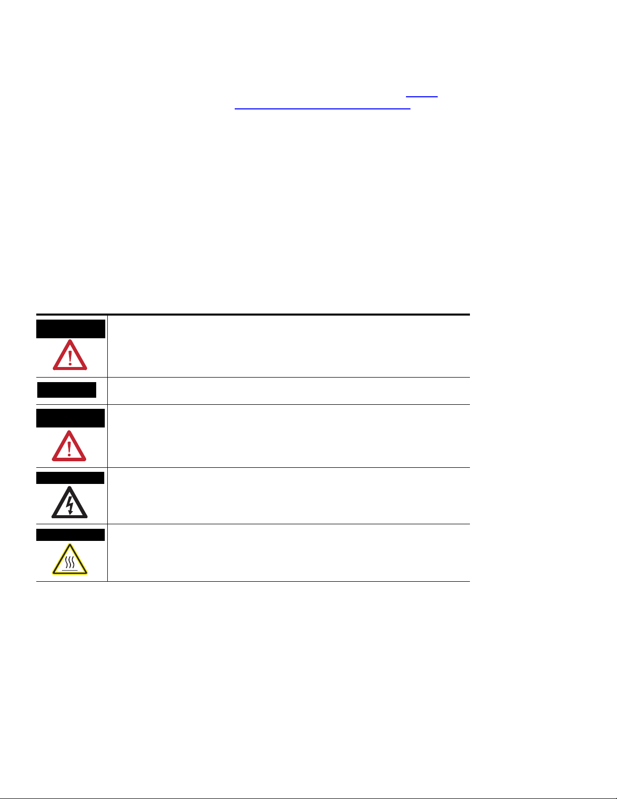
Throughout this manual, when necessary, we use notes to make you aware of safety considerations.
available from your local
) describes some important differences
WARNING
Identifies information about practices or circumstances that can cause an explosion in a
hazardous environment, which may lead to personal injury or death, property damage, or
economic loss.
IMPORTANT
ATTENTION
Identifies information that is critical for successful application and understanding of the product.
Identifies information about practices or circumstances that can lead to personal injury or death,
property damage, or economic loss. Attentions help you identify a hazard, avoid a hazard, and
recognize the consequence
SHOCK HAZARD
Labels may be on or inside the equipment, for example, a drive or motor, to alert people that
dangerous voltage may be present.
BURN HAZARD
Labels may be on or inside the equipment, for example, a drive or motor, to alert people that
surfaces may reach dangerous temperatures.
Allen-Bradley, Rockwell Automation, RSLogix 5000, ControlLogix, ProcessLogix, RSLinx, ControlFlash, and TechConnect are trademarks of Rockwell Automation, Inc.
Trademarks not belonging to Rockwell Automation are property of their respective companies.
Page 3

Table of Contents
Preface
Introduction
Configure the 1757-ABRIO Module
Purpose of this Manual . . . . . . . . . . . . . . . . . . . . . . . . . . . . . 7
Who Should Use this Manual. . . . . . . . . . . . . . . . . . . . . . . . . 7
Additional Resources. . . . . . . . . . . . . . . . . . . . . . . . . . . . . . . 7
Chapter 1
Introduction . . . . . . . . . . . . . . . . . . . . . . . . . . . . . . . . . . . . . 9
Process Remote I/O (RIO) Communication Interface Module . 9
RSLinx Software Requirements. . . . . . . . . . . . . . . . . . . . . . . 10
ProcessLogix System Quick Start . . . . . . . . . . . . . . . . . . . . . 11
RSLogix 5000 System Quick Start . . . . . . . . . . . . . . . . . . . . . 12
Update the 1757-ABRIO Module’s Firmware. . . . . . . . . . . . . 14
Using ControlFlash Software. . . . . . . . . . . . . . . . . . . . . . 14
Using NTools with ProcessLogix Software. . . . . . . . . . . . 15
Chapter 2
Introduction . . . . . . . . . . . . . . . . . . . . . . . . . . . . . . . . . . . . 17
AbRioCfg Software Overview. . . . . . . . . . . . . . . . . . . . . . . . 17
Mapping and Accessing RIO Network Data . . . . . . . . . . . . . 18
Installing AbRioCfg Software . . . . . . . . . . . . . . . . . . . . . . . . 19
Autoconfigure the I/O Racks . . . . . . . . . . . . . . . . . . . . . . . . 19
Adding Block Transfer Modules. . . . . . . . . . . . . . . . . . . . . . 23
Addressing Modes for 1771 . . . . . . . . . . . . . . . . . . . . . . 24
Configuring Block Transfer Modules . . . . . . . . . . . . . . . . . . 25
Scaling . . . . . . . . . . . . . . . . . . . . . . . . . . . . . . . . . . . . . . . . 26
Input Scaling . . . . . . . . . . . . . . . . . . . . . . . . . . . . . . . . . 26
Output Scaling. . . . . . . . . . . . . . . . . . . . . . . . . . . . . . . . 27
Tags Defined . . . . . . . . . . . . . . . . . . . . . . . . . . . . . . . . . . . 28
Create a Tag . . . . . . . . . . . . . . . . . . . . . . . . . . . . . . . . . 30
Mapping Data to Tags in AbRioCfg Software . . . . . . . . . . . . 31
Block Transfers . . . . . . . . . . . . . . . . . . . . . . . . . . . . . . . 31
I/O . . . . . . . . . . . . . . . . . . . . . . . . . . . . . . . . . . . . . . . . 32
Deleting Mapped Data . . . . . . . . . . . . . . . . . . . . . . . . . . 32
Tips for Configuring Modules . . . . . . . . . . . . . . . . . . . . . . . 32
Add Racks Offline . . . . . . . . . . . . . . . . . . . . . . . . . . . . . 33
Delete Racks Offline . . . . . . . . . . . . . . . . . . . . . . . . . . . 34
Change the Baud Rate Offline . . . . . . . . . . . . . . . . . . . . 35
Download the Configuration . . . . . . . . . . . . . . . . . . . . . . . . 35
Upload the Configuration . . . . . . . . . . . . . . . . . . . . . . . . . . 36
3Publication 1757-UM007D-EN-P - December 2008 3
Page 4

Table of Contents
Creating Generic Modules in
AbRioCfg Software
Configuring the ProcessLogix
Controller to Access Data on the
1757-ABRIO Module
Chapter 3
Introduction . . . . . . . . . . . . . . . . . . . . . . . . . . . . . . . . . . . . 37
Generic Module Overview. . . . . . . . . . . . . . . . . . . . . . . . . . 37
Generic Module Configuration File . . . . . . . . . . . . . . . . . . . 38
Configuration Block Transfer Write. . . . . . . . . . . . . . . . . 38
Data Block Transfer Read. . . . . . . . . . . . . . . . . . . . . . . . 41
Data Block Transfer Write . . . . . . . . . . . . . . . . . . . . . . . 45
Creating a Generic Module in AbRioCfg software . . . . . . . . . 48
Chapter 4
Introduction . . . . . . . . . . . . . . . . . . . . . . . . . . . . . . . . . . . . 51
Modes of Operation . . . . . . . . . . . . . . . . . . . . . . . . . . . . . . 51
CONFIG Mode. . . . . . . . . . . . . . . . . . . . . . . . . . . . . . . . 51
INACTIVE Mode . . . . . . . . . . . . . . . . . . . . . . . . . . . . . . 52
ACTIVE Mode (Run) . . . . . . . . . . . . . . . . . . . . . . . . . . . 52
FORCED ACTIVE Mode . . . . . . . . . . . . . . . . . . . . . . . . . 52
Configure the 1757-PLX52 Controller . . . . . . . . . . . . . . . . . . 53
Configuring RSLogix 5000
Software to Access Data on the
1757-ABRIO Module
Accessing Data through a DDE or
OPC Server
Chapter 5
Introduction . . . . . . . . . . . . . . . . . . . . . . . . . . . . . . . . . . . . 57
Modes of Operation . . . . . . . . . . . . . . . . . . . . . . . . . . . . . . 57
CONFIG Mode. . . . . . . . . . . . . . . . . . . . . . . . . . . . . . . . 57
INACTIVE Mode . . . . . . . . . . . . . . . . . . . . . . . . . . . . . . 58
ACTIVE Mode (Run) . . . . . . . . . . . . . . . . . . . . . . . . . . . 58
FORCED ACTIVE Mode . . . . . . . . . . . . . . . . . . . . . . . . . 59
Scheduled Digital I/O Connections in RSLogix 5000 Programs .
60
Scheduled Connection Types . . . . . . . . . . . . . . . . . . . . . 60
Setup an Exclusive-owner Connection . . . . . . . . . . . . . . 60
Setup Input-only Connections . . . . . . . . . . . . . . . . . . . . 63
Unscheduled I/O Connections in ControlLogix. . . . . . . . . . . 67
Create Message Commands to Read and Write All RIO
Network Data . . . . . . . . . . . . . . . . . . . . . . . . . . . . . . . . 68
Chapter 6
Introduction . . . . . . . . . . . . . . . . . . . . . . . . . . . . . . . . . . . . 75
Accessing Data from a DDE or OPC Server . . . . . . . . . . . . . 75
Configuring a Topic in RSLinx Software . . . . . . . . . . . . . 75
Accessing the Data. . . . . . . . . . . . . . . . . . . . . . . . . . . . . 76
4 Publication 1757-UM007D-EN-P - December 2008
Page 5

Monitoring the 1757-ABRIO
Module
Supported 1771 Modules
Table of Contents
Chapter 7
Introduction . . . . . . . . . . . . . . . . . . . . . . . . . . . . . . . . . . . . 77
Monitoring the Operation . . . . . . . . . . . . . . . . . . . . . . . . . . 77
Monitoring Digital I/O. . . . . . . . . . . . . . . . . . . . . . . . . . . . . 77
Monitoring the Data Value of Tags. . . . . . . . . . . . . . . . . . . . 78
Monitoring the Status of a Block Transfer. . . . . . . . . . . . . . . 79
Monitoring the Scanner Log. . . . . . . . . . . . . . . . . . . . . . . . . 80
Monitoring Diagnostic Counters. . . . . . . . . . . . . . . . . . . . . . 81
Active Rack List . . . . . . . . . . . . . . . . . . . . . . . . . . . . . . . 81
Global Diagnostic Counters . . . . . . . . . . . . . . . . . . . . . . 81
Fatal Errors . . . . . . . . . . . . . . . . . . . . . . . . . . . . . . . . . . . . . 82
Chapter 8
Introduction . . . . . . . . . . . . . . . . . . . . . . . . . . . . . . . . . . . . 83
Module Description. . . . . . . . . . . . . . . . . . . . . . . . . . . . . . . 83
1771-IFE Module. . . . . . . . . . . . . . . . . . . . . . . . . . . . . . . . . 84
Module Configuration . . . . . . . . . . . . . . . . . . . . . . . . . . 85
I/O Data . . . . . . . . . . . . . . . . . . . . . . . . . . . . . . . . . . . . 87
Diagnostic Data . . . . . . . . . . . . . . . . . . . . . . . . . . . . . . . 87
1771-OFE Module . . . . . . . . . . . . . . . . . . . . . . . . . . . . . . . . 89
Module Configuration . . . . . . . . . . . . . . . . . . . . . . . . . . 89
I/O Data . . . . . . . . . . . . . . . . . . . . . . . . . . . . . . . . . . . . 90
Diagnostic Data . . . . . . . . . . . . . . . . . . . . . . . . . . . . . . . 91
1771-IR Module. . . . . . . . . . . . . . . . . . . . . . . . . . . . . . . . . . 92
Module Configuration . . . . . . . . . . . . . . . . . . . . . . . . . . 92
I/O Data . . . . . . . . . . . . . . . . . . . . . . . . . . . . . . . . . . . . 94
Diagnostic Data . . . . . . . . . . . . . . . . . . . . . . . . . . . . . . . 94
1771-IXE Module . . . . . . . . . . . . . . . . . . . . . . . . . . . . . . . . 95
Module Configuration . . . . . . . . . . . . . . . . . . . . . . . . . . 95
I/O Data . . . . . . . . . . . . . . . . . . . . . . . . . . . . . . . . . . . . 96
Diagnostic Data . . . . . . . . . . . . . . . . . . . . . . . . . . . . . . . 97
1771-IL Module. . . . . . . . . . . . . . . . . . . . . . . . . . . . . . . . . . 98
Module Configuration . . . . . . . . . . . . . . . . . . . . . . . . . . 98
I/O Data . . . . . . . . . . . . . . . . . . . . . . . . . . . . . . . . . . . . 99
Diagnostic Data . . . . . . . . . . . . . . . . . . . . . . . . . . . . . . 100
1771-NOC Module . . . . . . . . . . . . . . . . . . . . . . . . . . . . . . 101
Module Configuration . . . . . . . . . . . . . . . . . . . . . . . . . 101
I/O Data . . . . . . . . . . . . . . . . . . . . . . . . . . . . . . . . . . . 102
Diagnostic Data . . . . . . . . . . . . . . . . . . . . . . . . . . . . . . 103
1771-NOV Module . . . . . . . . . . . . . . . . . . . . . . . . . . . . . . 104
Module Configuration . . . . . . . . . . . . . . . . . . . . . . . . . 104
I/O Data . . . . . . . . . . . . . . . . . . . . . . . . . . . . . . . . . . . 105
Diagnostic Data . . . . . . . . . . . . . . . . . . . . . . . . . . . . . . 106
Publication 1757-UM007D-EN-P - December 2008 5
Page 6

Table of Contents
Accessing HART Data
1771-NIV Module . . . . . . . . . . . . . . . . . . . . . . . . . . . . . . . 107
Module Configuration . . . . . . . . . . . . . . . . . . . . . . . . . 107
I/O Data . . . . . . . . . . . . . . . . . . . . . . . . . . . . . . . . . . . 108
Diagnostic Data . . . . . . . . . . . . . . . . . . . . . . . . . . . . . . 109
1771-NR Module . . . . . . . . . . . . . . . . . . . . . . . . . . . . . . . . 110
Module Configuration . . . . . . . . . . . . . . . . . . . . . . . . . 111
I/O Data . . . . . . . . . . . . . . . . . . . . . . . . . . . . . . . . . . . 113
Diagnostic Data . . . . . . . . . . . . . . . . . . . . . . . . . . . . . . 113
Chapter 9
Introduction . . . . . . . . . . . . . . . . . . . . . . . . . . . . . . . . . . . 115
Sending HART Commands Using RSLogix 5000 Software MSG .
115
HART Command Data . . . . . . . . . . . . . . . . . . . . . . . . . 117
Reply Data. . . . . . . . . . . . . . . . . . . . . . . . . . . . . . . . . . 120
Example: HART Command 36 . . . . . . . . . . . . . . . . . . . 122
1770-HT1 Module . . . . . . . . . . . . . . . . . . . . . . . . . . . . . . . 123
Rack Requirements . . . . . . . . . . . . . . . . . . . . . . . . . . . 123
Configuring the 1770-HT1 Module . . . . . . . . . . . . . . . . 124
HART Command status . . . . . . . . . . . . . . . . . . . . . . . . 129
Specifications
Troubleshooting
Appendix A
. . . . . . . . . . . . . . . . . . . . . . . . . . . . . . . . . . . . . . . . . . . . 131
Appendix B
Interpret the Status Indicators . . . . . . . . . . . . . . . . . . . . . . 133
RIO Status Indicator – Remote Devices Status . . . . . . . . 133
SYS Status Indicator – ControlBus Status . . . . . . . . . . . . 133
OK Status Indicator – Module Health . . . . . . . . . . . . . . 134
Status Display Power-up Messages. . . . . . . . . . . . . . . . . . . 134
Power Supply Indicator. . . . . . . . . . . . . . . . . . . . . . . . . . . 134
Interpret the Alphanumeric Display . . . . . . . . . . . . . . . . . . 135
Using AbRioCfg Software for Troubleshooting . . . . . . . . . . 136
Troubleshooting Problems. . . . . . . . . . . . . . . . . . . . . . . . . 137
Using RSLogix 5000 to Diagnose Problems. . . . . . . . . . . . . 138
General Tab . . . . . . . . . . . . . . . . . . . . . . . . . . . . . . . . 138
Connection Tab . . . . . . . . . . . . . . . . . . . . . . . . . . . . . . 138
Module Info Tab . . . . . . . . . . . . . . . . . . . . . . . . . . . . . 139
Backplane Tab. . . . . . . . . . . . . . . . . . . . . . . . . . . . . . . 139
Using Control Builder Software to Diagnose Problems . . . . 140
Troubleshooting 1757-ABRIO Module Communications . . . 140
6 Publication 1757-UM007D-EN-P - December 2008
Page 7

Operational Comparison Between
the 1757-ABRIO Module and a
PLC-5 System
Tag Descriptions for Scheduled
Data in RSLogix 5000 Software
Table of Contents
Appendix C
Normal Operational Messages . . . . . . . . . . . . . . . . . . . . . . 143
Exception Handling Messages . . . . . . . . . . . . . . . . . . . . . . 145
Appendix D
Configuration Tag . . . . . . . . . . . . . . . . . . . . . . . . . . . . 149
I and O Tags . . . . . . . . . . . . . . . . . . . . . . . . . . . . . . . . 149
Status Tag . . . . . . . . . . . . . . . . . . . . . . . . . . . . . . . . . . 151
Publication 1757-UM007D-EN-P - December 2008 7
Page 8

Table of Contents
8 Publication 1757-UM007D-EN-P - December 2008
Page 9
Preface
Purpose of this Manual
Who Should Use this Manual
Additional Resources
This manual describes how to configure and troubleshoot your
Process Remote I/O (RIO) Communication Interface Module.
For installation information, refer to the Process Remote I/O (RIO)
Communication Interface Module Installation Instructions, publication
1757-IN916
We assume you have a good understanding of Remote I/O (RIO)
modules as well as the host controller system (ProcessLogix or
ControlLogix).
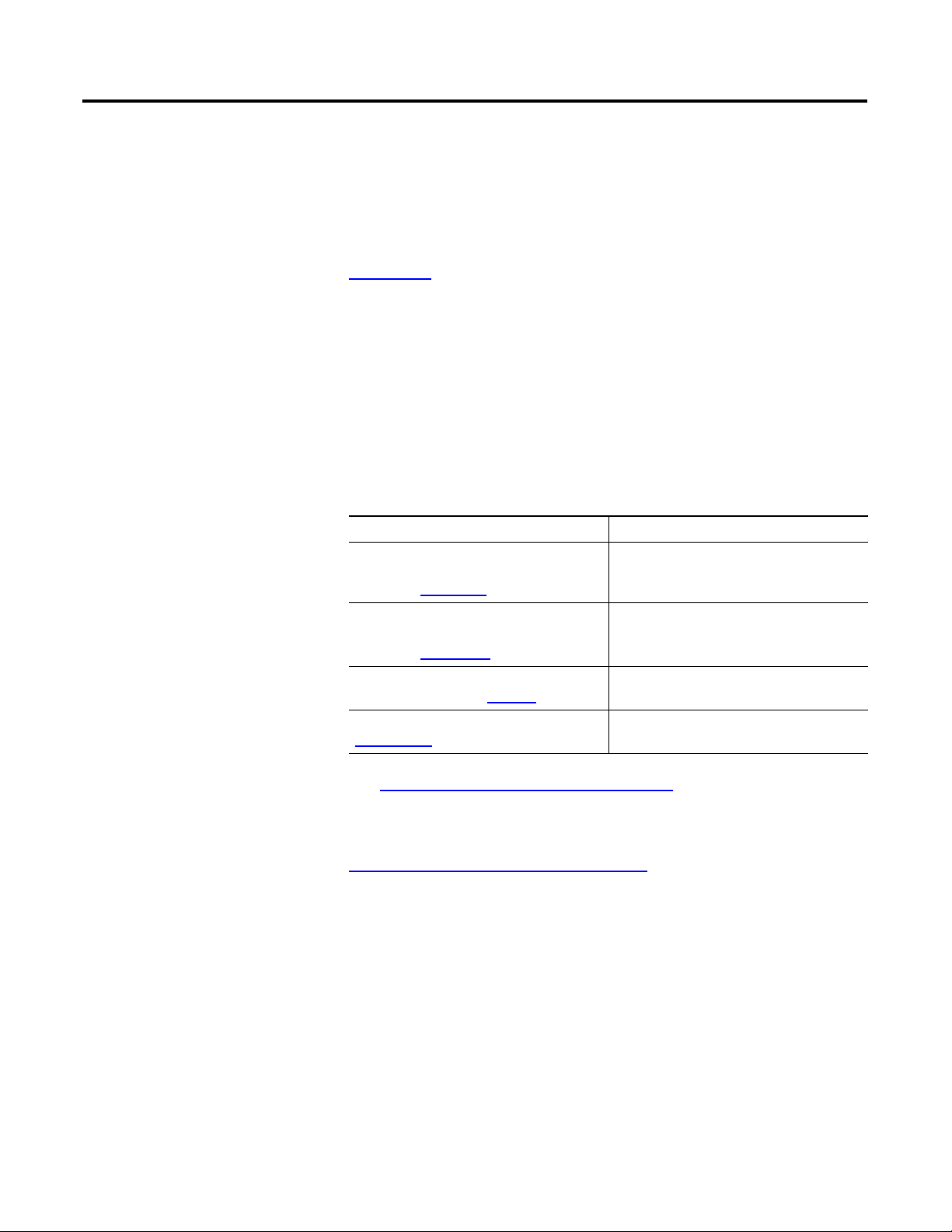
These documents contain additional information concerning related
Rockwell Automation products.
Resource Description
Process Remote I/O (RIO) Communication
Interface Module Installation Instructions,
publication 1757-IN916
Process Remote I/O (RIO) Communication
Interface Module Release Notes,
publication 1757-RN520
Industrial Automation Wiring and Grounding
Guidelines, publication 1770-4.1
.
Provides details on how to install the
1757-ABRIO module.
Provides release details on the 1757-ABRIO
module.
Provides general guidelines for installing a
Rockwell Automation industrial system.
Product Certifications website,
http://ab.com
See I/O Module Documentation
ControlLogix documentation.
You can view or download publications at
http://literature.rockwellautomation.com
technical documentation, contact your local Rockwell Automation
distributor or sales representative.
Provides declarations of conformity,
certificates, and other certification details.
on page 84 for a listing of related
. To order paper copies of
7Publication 1757-UM007D-EN-P - December 2008 7
Page 10

Table of Contents Preface
8 Publication 1757-UM007D-EN-P - December 2008
Page 11
Introduction
Chapter
1
Introduction
Process Remote I/O (RIO) Communication Interface Module
ProcessLogix
System Server
ProcessLogix and ControlLogix Controllers
This chapter:
describes the 1757-ABRIO Remote I/O Module.
lists the RSLinx software requirements.
provides update procedures for the module’s firmware.
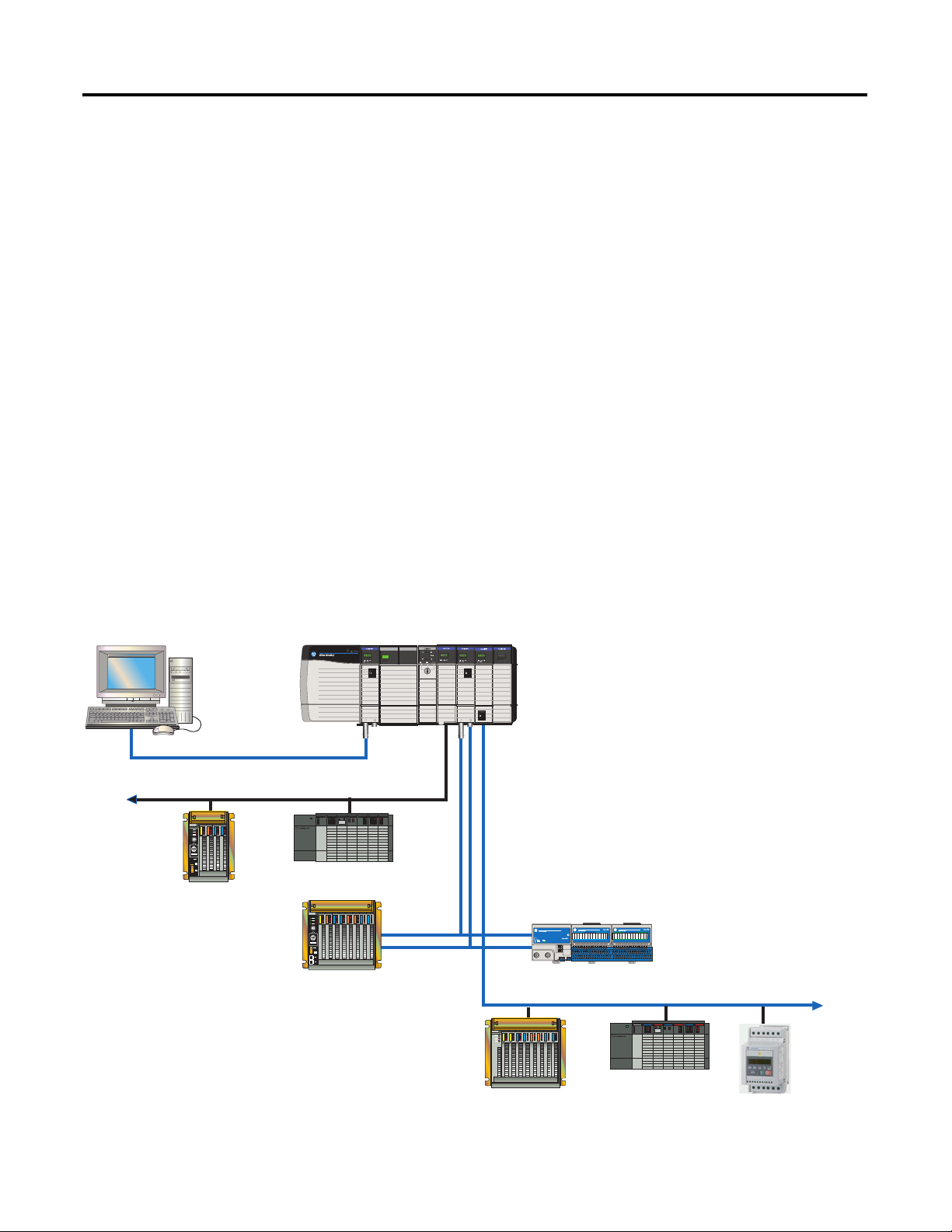
This document is a user guide for the 1757-ABRIO module, which lets
Rockwell Automation controllers (ProcessLogix or ControlLogix)
communicate with Allen-Bradley remote I/O. The module acts as a
RIO network scanner. The 1757-ABRIO module facilitates connection
to analog and discrete I/O devices as well as any block transfer
modules.
1757-ABRIO Module Example Topology
ControlNet Network
Data Highway + Network
ControlNet
Network
SLC Controller
PLC5
Controller
PLC5/C
Controller
43290
1771 Remote I/O
9Publication 1757-UM007D-EN-P - December 2008 9
Flex Ex Modules
Remote I/O Network
1746 Remote I/O
Drive
Supports
Block
Transfers limit of 32
words in a
block
Page 12

Chapter 1 Introduction
As an RIO network scanner, the module:
scans 1771 racks with rack numbers from 1 to 37 octal.
supports baud rates of 57.6, 115.2 and 230.4 kilobaud.
supports up to 32 adapters with any mix of full/partial racks.
automatically manages and performs block transfers, update
time can be defined for each block transfer.
provides full diagnostic counters for alarms and maintenance.
automatically performs scaling of raw analog data.
supports scheduled connections to update digital data with a
ControlLogix controller.
implements a watchdog timer in the module’s hardware.
If the firmware does not kick the watchdog within the time-out
period the watchdog times out and places the module into the
configured safe failure state.
automatically provides fault/fail safe commands to I/O modules
and controllers.
RSLinx Software Requirements
implements a jabber inhibit timer.
If the network transmitter is on longer than 150% of the longest
network frame time, the 1757-ABRIO module turns the
transmitter off and places the module into the configured safe
failure state.
supports firmware updates using NTools or ControlFlash
software.
supports direct DDE/OPC data access.
provides support for Rockwell Automation’s 1770-HT1,
1770-HT8, and 1770-HT16 HART interface products.
provides HART command set for calibration and diagnostics.
The AbRioCfg software requires RSLinx OEM software or above. You
cannot use RSLinx Lite software. To access the module using OPC or
DDE, you must have RSLinx 2.31 software or above.
If you are using ProcessLogix software, refer to the corresponding
ProcessLogix Installation and Upgrade Guide to determine the
appropriate RSLinx software version for your release.
10 Publication 1757-UM007D-EN-P - December 2008
Page 13

Introduction Chapter 1
ProcessLogix System Quick Start
Use the following steps to quickly get the module running in a
ProcessLogix system. Detailed information about each step is available
in other sections of this manual or in the installation manual. You can
only have one scanner per RIO network. Remove any other scanners
on the RIO network before continuing.
1. Install the 1757-ABRIO module in the chassis and connect it to
the RIO network.
See the Process Remote I/O (RIO) Communication Interface
Module Installation Instructions, publication 1757-IN916
2. Flash the controller with the latest firmware.
See Using NTools with ProcessLogix Software
3. Install the AbRioCfg software.
See Installing AbRioCfg Software
4. Autoconfigure or manually configure the RIO racks. This step
locates all connected racks.
on page 19.
on page 15.
.
See Autoconfigure the I/O Racks
Offline on page 33.
5. Add and configure block transfer modules.
See Adding Block Transfer Modules
6. Create tags for access by the ProcessLogix controller.
See Create a Tag
7. Map I/O data to the tags and save the configuration file.
See Mapping Data to Tags in AbRioCfg
8. Download the configuration to the 1757-ABRIO module.
See Download the Configuration
9. Configure the ProcessLogix controller to access information
within the 1757-ABRIO module using Control Builder software.
See Configure the 1757-PLX52 Controller
on page 30.
on page 19 and Add Racks
on page 23.
Software on page 31.
on page 35.
on page 53.
10. Access live data from the 1757-ABRIO module.
See Live Data Examples
Publication 1757-UM007D-EN-P - December 2008 11
on page 56.
Page 14

Chapter 1 Introduction
RSLogix 5000 System Quick Start
Use the following steps to quickly get the module running in an
RSLogix 5000 system. Detailed information about each step is
available in other sections of this manual or in the installation manual.
You can only have one scanner per RIO network. Remove any other
scanners on the RIO network before continuing.
1. Install the 1757-ABRIO module in the chassis and connect it to
the RIO network.
See the Process Remote I/O (RIO) Communication Interface
Module Installation Instructions, publication 1757-IN916
2. Flash the Controller with the latest firmware.
See Using ControlFlash Software
3. Install the AbRioCfg software.
See Installing AbRioCfg Software
4. Autoconfigure or manually configure the RIO racks. This step
locates all connected racks.
on page 14.
on page 19.
.
See Autoconfigure the I/O Racks
Offline on page 33.
5. Add and configure block transfer modules.
See Adding Block Transfer Modules
6. Create tags to access analog data from the ControlLogix
controller.
See Create a Tag
OR
Use scheduled updates to access digital data from the
ControlLogix controller.
See Scheduled Digital I/O Connections in RSLogix 5000
Programs on page 60.
7. Map I/O data to the tags and save the configuration file.
See Mapping Data to Tags in AbRioCfg
on page 30.
on page 19 and Add Racks
on page 23.
Software on page 31.
8. Download the configuration to 1757-ABRIO module.
See Download the Configuration
12 Publication 1757-UM007D-EN-P - December 2008
on page 35.
Page 15

Introduction Chapter 1
9. If you are using:
a. a scheduled network, establish an Exclusive Owner or Input
Only connection from the ControlLogix controller to access
digital data within the 1757-ABRIO module.
See Setup an Exclusive-owner Connection
Setup Input-only Connections
on page 63.
on page 60 or
b. an unscheduled network, configure tags and ladder logic in
RSLogix 5000 software to access information within the
1757-ABRIO module.
See Unscheduled I/O Connections in ControlLogix
on
page 67.
TIP
If you are using a scheduled ControlNet network, you
must also complete 9b to access analog or text data
from the 1757-ABRIO module.
10. If you are using a scheduled ControlNet network, schedule your
network through RSNetWorx for ControlNet software.
See the RSNetWorx Help and the ControlNet Modules in
Logix5000 Control Systems User Manual, publication
CNET-UM001
.
11. Access live data from the 1757-ABRIO module via:
a. scheduled connections.
See Scheduled Digital I/O Connections in RSLogix 5000
Programs on page 60 and Live Data Example on page 66.
b. unscheduled connections.
See Unscheduled I/O Connections in ControlLogix
on
page 67 and Live Data Example on page 73.
Publication 1757-UM007D-EN-P - December 2008 13
Page 16
Chapter 1 Introduction
Update the 1757-ABRIO Module’s Firmware
The 1757-ABRIO module supports firmware upgrades using
ControlFLASH or NTools software. The firmware version is displayed
on the 1757-ABRIO module’s 4-character display when you power up
the module.
For ProcessLogix software users, if your 1757-ABRIO module revision
is:
at or less than 1.2, use ControlFlash software to update the
module firmware.
greater than 1.2, use NTools software to update the module
firmware.
IMPORTANT
The module ships with the latest firmware installed.
You do not need to download firmware to the
1757-ABRIO module when you first receive it.
Using ControlFlash Software
Use the following procedure to update the module firmware using
ControlFLASH software.
1. Insert the 1757-ABRIO CD.
2. Click Start>Run.
3. Type this path or Browse to:
D:(or your CD-ROM drive letter)\ControlFlash\setup.exe
4. Click OK.
5. At the Welcome to ControlFLASH Setup window, click Next.
6. To accept the License Agreement, click Yes.
7. To accept the default location, click Next.
8. At the Setup Complete window,
a. Uncheck the Yes, I want to view the README file checkbox.
b. Check the Yes, I want to launch ControlFLASH checkbox.
c. Click Finish.
9. At the Welcome to ControlFLASH window, click Next.
14 Publication 1757-UM007D-EN-P - December 2008
Page 17

Introduction Chapter 1
10. Click 1757-ABRIO and click Next.
11. Expand the RSLinx Tree window to the location of the
1757-ABRIO module you wish to flash.
12. Select the module icon and click OK.
13. Confirm new revision for this update and click Next.
14. At the Summary window, click Finish.
15. To confirm the flash, click Yes.
16. Click OK.
If this update is successful, the Update Status window displays
the following message in green:
Update Complete. Please verify this new firmware update before
using the target device in its intended application.
17. Click OK and then click Cancel at the Welcome to ControlFLASH
Setup window.
18. Click Yes to end the configuration session.
Using NTools with ProcessLogix Software
On a ProcessLogix system, if the module firmware is at 1.2 or greater,
use the following procedure to update the module firmware using
NTools.
1. On the ProcessLogix Server, click Start>Run.
2. Type >ntools -c -u<.
3. To launch the Network Tools application, click OK.
4. Click OK at the warning about monitoring through Control
Builder software.
5. To initiate the network scan, click Resume.
6. Select the appropriate CNB or ENET icon.
7. Select the module to be updated in the chassis graphic.
Publication 1757-UM007D-EN-P - December 2008 15
Page 18

Chapter 1 Introduction
8. Click the firmware button and click Yes to acknowledge the
warning.
9. Navigate to:
D:(or your CD-ROM drive letter)\Firmware_NTools
10. Select the appropriate .nvs file.
11. To start the firmware load, click Open.
12. To confirm, click Yes.
The Status field in the lower portion of the Network Tools
window tracks the load progress.
13. When the load completes, click OK.
16 Publication 1757-UM007D-EN-P - December 2008
Page 19

Configure the 1757-ABRIO Module
Chapter
2
Introduction
AbRioCfg Software Overview
This chapter:
provides an overview of the AbRioCfg software.
gives an introduction to mapping and accessing RIO network
data.
explains how to install the AbRioCfg software.
explains how to autoconfigure I/O racks.
explains how to add and configure block transfer modules.
The 1757-ABRIO module ships with configuration software, called
AbRioCfg. This configuration software is an online configuration tool.
Use the configuration software to:
query the RIO network to determine the location and size of the
racks present.
manually add and configure racks present in RIO network.
add and configure supported block transfer modules.
import comma separated variable files to define the Generic
Module as any block transfer module that uses 16-bit integer
data.
add, edit, and delete racks offline.
create tags for access by the controller.
map I/O data to those tags.
download the configuration to the module, using RSLinx
software.
monitor data and diagnostics on the module.
change the baud rate of network communications in a
configuration and download to the module.
change the configuration of racks in a configuration and
download to the module.
upload a configuration from a module.
print the configuration.
17Publication 1757-UM007D-EN-P - December 2008 17
Page 20
Chapter 2 Configure the 1757-ABRIO Module
Mapping and Accessing RIO Network Data
Use the provided AbRioCfg software to create tags which are arrays of
digital, floating point or text values that the host controller reads or
writes using unscheduled messages.
You map data that the module receives or sends into these tags. The
data mapping is stored in flash memory on the 1757-ABRIO module.
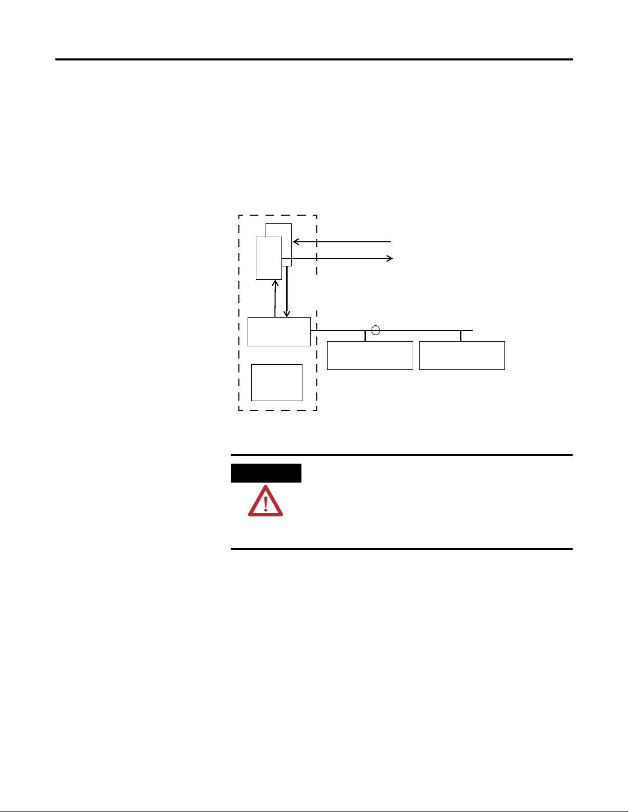
The 1757-ABRIO Module and Data Mapping
1757-ABRIO Module
Tag
Tag
RIO Network
Scanner
Scan
List
Write Data
Read Data
R/W Analog Data with Block Transfer Status
R/W digital Data
Scales Analog Data
Remote I/O
Modules
Analog/Digital Modules
Hard Configured for Safe/Fault States
ControlLogix or
ProcessLogix
Controller
RIO Network
Remote I/O
Modules
WARNING
It is essential that the control program on the host controller
matches the addresses in the mapping configuration on the
1757-ABRIO module. Otherwise the control program may
inadvertently write to the incorrect I/O locations. If you change
the data mappings on the 1757-ABRIO module, make sure that
the control program is using the correct addresses.
18 Publication 1757-UM007D-EN-P - December 2008
Page 21
Configure the 1757-ABRIO Module Chapter 2
Installing AbRioCfg Software
1. Verify that RSLinx software and RSLinx OEM or RSLinx
Professional (not RSLinx Lite) software is installed before you
install the AbRioCfg software.
2. Insert the CD supplied with the 1757-ABRIO module and run the
program setup.exe.
3. Confirm that you have RSLinx OEM or RSLinx Professional (not
RSLinx Lite) software installed.
IMPORTANT
Before you install a new version of AbRioCfg software, you must
delete the old version. Use the Add or Remove Programs utility in
your Windows Control Panel to remove the previous version.
IMPORTANT
Messages about the DTL32.DLL during installation or when you
run the software indicate problems with the RSLinx software
installation.
If you get these messages, install the proper version of RSLinx
software before you continue.
Removing the software does not delete stored configuration
files.
Autoconfigure the I/O Racks
TIP
The first step in building a configuration is to perform an
autoconfiguration. To complete an autoconfiguration, the RIO
network must be connected to the 1757-ABRIO module and the
module must be in “inactive” mode.
ATTENTION
1. Start AbRioCfg software.
If you see question marks for the 1757-ABRIO module when
running RSNetWorx or RSLinx software, install the EDS file
from the provided CD.
You do not need to load the firmware on the CD into your
1757-ABRIO module as the module ships with the latest version
of firmware. The firmware is on the CD for archival purposes
only.
When using AbRioCfg software, you must left-click to
select/highlight before you can right-click to activate menu
options.
Publication 1757-UM007D-EN-P - December 2008 19
Page 22
Chapter 2 Configure the 1757-ABRIO Module
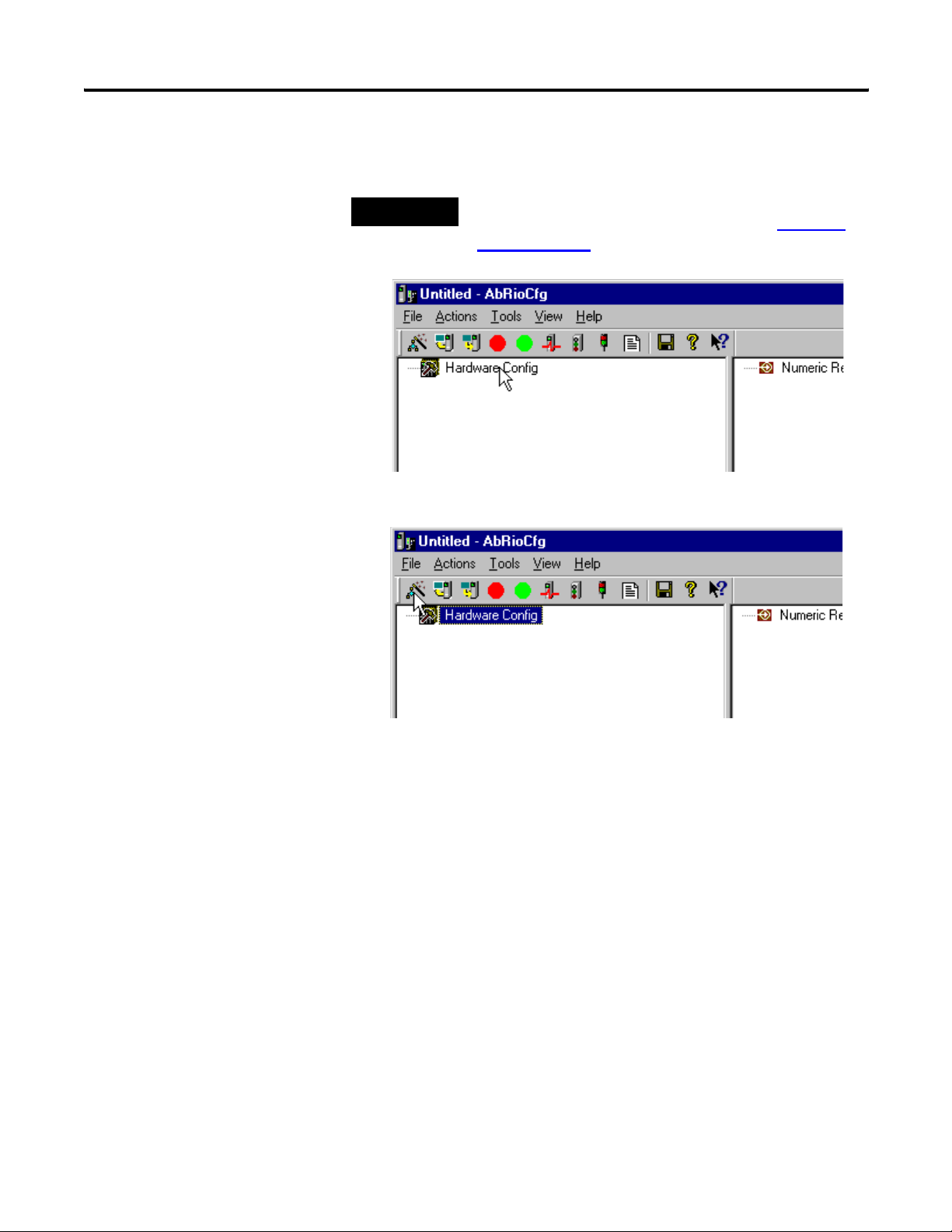
2. Click Hardware Config to highlight it and activate the AbRioCfg
menu toolbar.
TIP
With AbRioCfg software, 2.0 and higher, you can also manually
configure the I/O racks in your network. Refer to Add Racks
Offline on page 33 for more information.
3. Click the Autoconfig button in the toolbar.
An RSWho window opens.
20 Publication 1757-UM007D-EN-P - December 2008
Page 23
Configure the 1757-ABRIO Module Chapter 2
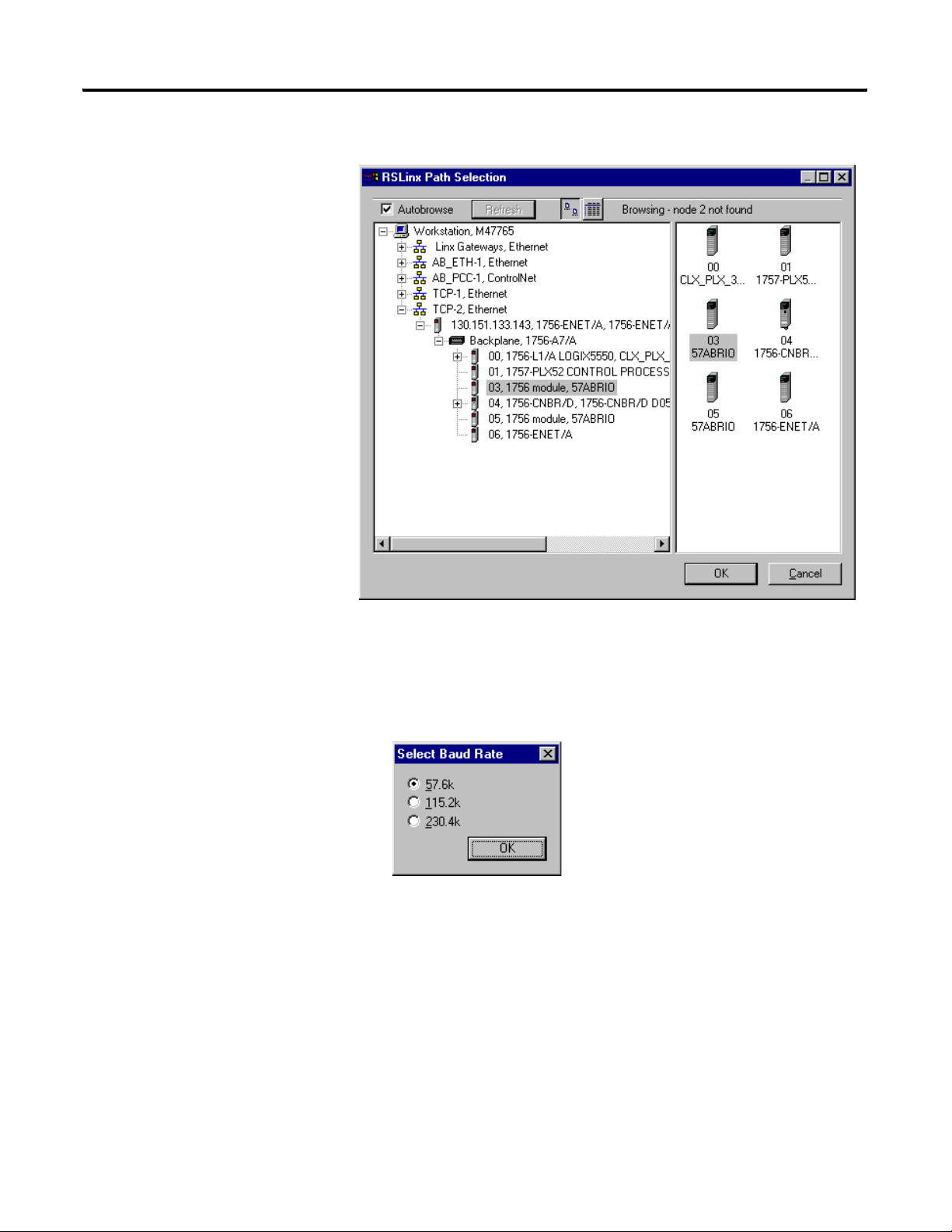
4. Navigate to the 1757-ABRIO module.
5. Select the module and click OK.
The Select Baud Rate dialog box opens.
6. Select the appropriate baud rate and click OK.
The baud rate in this example is set by
switches on the 1771-ASB adapter. See
your device documentation for how to
set the desired baud rate. All racks or
devices on one RIO network must
operate at the same baud rate.
Publication 1757-UM007D-EN-P - December 2008 21
Page 24
Chapter 2 Configure the 1757-ABRIO Module
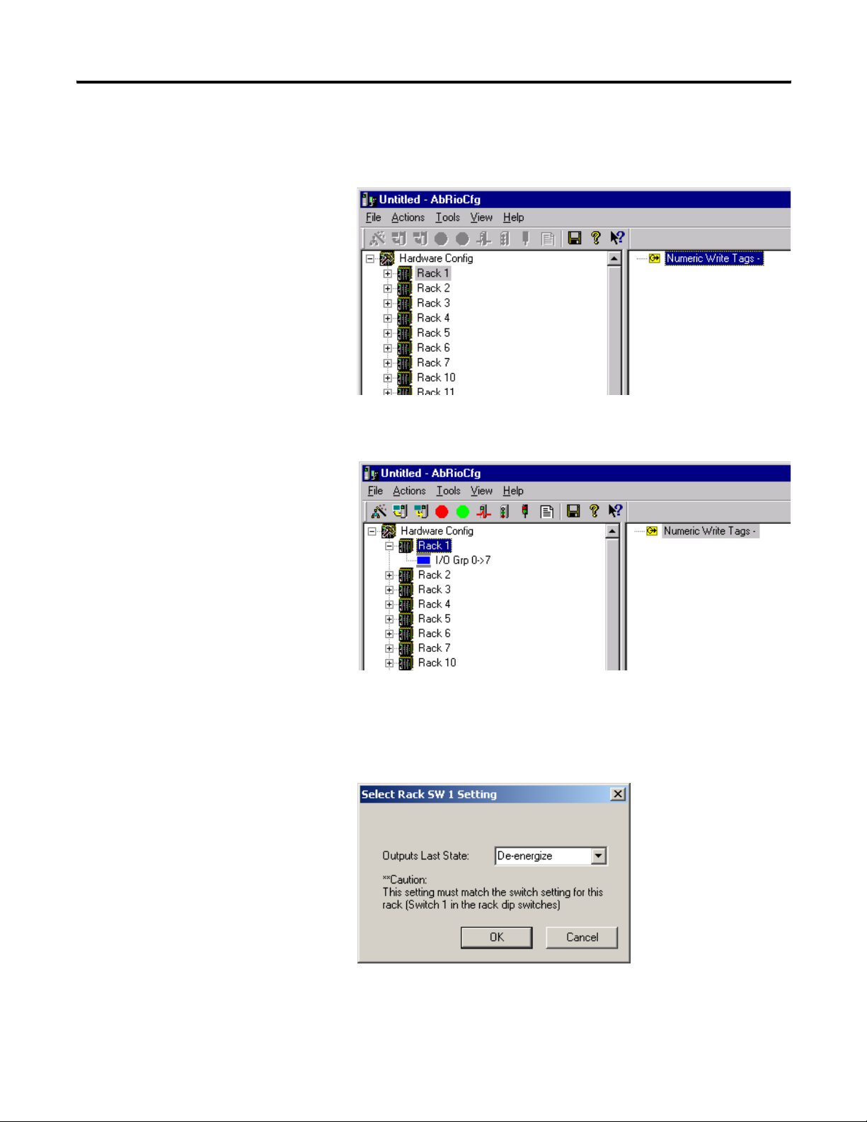
The 1757-ABRIO module sends messages to all possible racks
and builds the network rack configuration from the responses. It
displays a list of the racks it found in the network tree.
If you expand a rack, the partial racks that make up that rack
number are displayed.
7. If you are using 1771 remote I/O modules,
a. Right-click the rack in the network tree and select Enter Rack
Switch Setting.
The Select Rack Setting dialog box opens.
22 Publication 1757-UM007D-EN-P - December 2008
Page 25
Configure the 1757-ABRIO Module Chapter 2
b. Select the value that matches the Last State switch setting in
the backplane of the I/O chassis, either De-energize or Hold
Last State.
This setting tells the 1757-ABRIO module what to do if the
controller stops updating the tag to which this chassis’s digital
data is mapped.
Adding Block Transfer Modules
c. Repeat steps 7a
I/O modules.
Autoconfiguration can locate the racks present on the network but it
cannot detect the analog I/O modules in those racks. Remote I/O
protocol does not allow for module identification to be communicated
on the network. Because of this, Block Transfer modules need to be
added manually. You do not have to add digital modules.
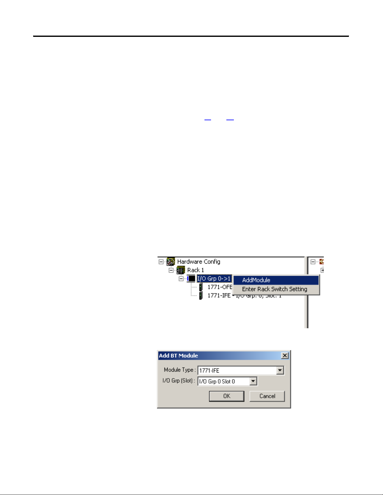
To add a block transfer module, complete the following steps.
1. Expand the rack that contains the analog I/O module in the
network tree.
2. Right-click the partial rack that contains the module and select
Add Module.
and 7b for all racks that contain 1771 remote
The Add BT Module dialog box opens.
3. Select the Module Type from the pull-down menu.
Publication 1757-UM007D-EN-P - December 2008 23
Page 26

Chapter 2 Configure the 1757-ABRIO Module
4. Select the slot location for the module.
To do this, you should be familiar with Allen-Bradley addresses
and, in particular, with 1771 addressing modes (see below).
See I/O Module Documentation
on page 84 for a list of related
ControlLogix documentation.
5. Click OK.
Addressing Modes for 1771
The 1771 chassis have three addressing modes - 1/2-slot, 1-slot and
2-slot addressing. The addressing mode is set by switches in the
backplane of the chassis and is set on a per-chassis basis. The
addressing mode determines how physical block transfer modules
map into logical addresses (rack, I/O group and slot).
In the following tables, the addresses used for modules in a 16-slot
rack in each addressing mode. The rack switches are set for rack 1,
starting I/O group 0.
As illustrated in the 2-slot addressing table below, the controller
addresses two I/O module slots as one I/O group. For example, for a
chassis at rack 1, starting I/O group 0, a block transfer module in the
first slot would be at address rack 1, I/O group 0, slot 0. A module in
the next slot would be at rack 1, I/O group 0, slot 1.
2-Slot Addressing
Slot in chassis0123456789101112131415
Rack 1111111111111111
I/O Group 0011223344556677
Slot 0101010101010101
As illustrated in the 1-slot addressing table below, the controller
addresses one I/O module slot as one I/O group. For example, for a
chassis at rack 1, starting I/O group 0, a block transfer module in the
first slot would be at address rack 1, I/O group 0, slot 0. A module in
the next slot would be at rack 1, I/O group 1, slot 0.
1-Slot Addressing
Slot in chassis0123456789101112131415
Rack 1111111122222222
I/O Group 0123456701234567
Slot 0000000000000000
24 Publication 1757-UM007D-EN-P - December 2008
Page 27
Configure the 1757-ABRIO Module Chapter 2
As illustrated in the 1/2-slot addressing table below, the controller
addresses 1/2 of an I/O module slot as one I/O group. For example,
for a chassis at rack 1, starting I/O group 0, a block transfer module in
the first slot would be at address rack 1, I/O group 0, slot 0. A module
in the next slot would be at rack 1, I/O group 2, slot 0.
1/2-Slot Addressing
Slot in chassis0123456789101112131415
Rack 1111222233334444
I/O Group 0246024602460246
Slot 0000000000000000
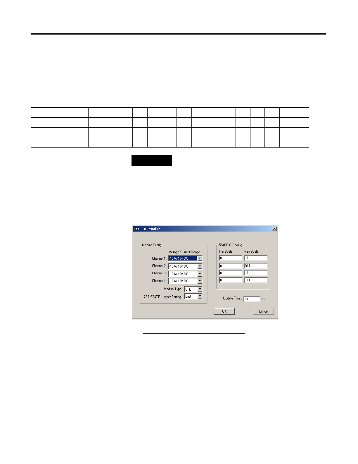
Configuring Block Transfer Modules
TIP
When you add a block transfer module, the configuration dialog box
for that module opens. The contents of the dialog box are specific to
each module type.
You cannot change the location of a module in the
configuration once you have created it. You must delete the
module and create a new one at the new location.
See Supported 1771 Modules
information on configuring individual modules.
To edit the configuration for a module, double-click the module in the
network tree, or right-click the module and select Configure.
Publication 1757-UM007D-EN-P - December 2008 25
on page 83 or the online help for
Page 28

Chapter 2 Configure the 1757-ABRIO Module
Scaling
Part of the configuration procedure for analog modules is entering
scaling values. The 1757-ABRIO module performs scaling between
raw I/O data and floating point user values.
You can send floating point output values to the 1757-ABRIO module
which it converts to raw output values using the scaling values you
supplied in the configuration. Similarly, the 1757-ABRIO module
converts raw input data to floating point values, using the scaling you
enter. The 1757-ABRIO module supports scaling values from -3.4e38
to 3.4e38. Scaling is done on a per-channel basis.
Input Scaling
For analog input modules, you must supply the floating point values
to which you want the minimum and maximum raw data scaled.
Minimum corresponds to the lowest raw value.
Maximum corresponds to the maximum raw value.
EXAMPLE
If a raw input range is 1 5 V dc and you set the minimum
scaling value to 12.3 and the maximum scaling value to 77.4,
a raw input voltage of 1 produces a scaled input value of 12.3.
A raw input voltage of 5 V dc produces a scaled input value of
77.4
A raw input value outside the range of 1 5 V dc produces an
input of NaN (not a number). Modules also have underrange
and overrange bits to indicate data overflows.
26 Publication 1757-UM007D-EN-P - December 2008
Page 29
Configure the 1757-ABRIO Module Chapter 2
Output Scaling
For output modules, you supply the floating point values you want to
correspond to the minimum and maximum raw output values.
ATTENTION
The minimum scale value may not be larger than the maximum
scale value
EXAMPLE
If a channel has a range of 1 5 V dc and you set the minimum
scaling value to 12.3 and the maximum scaling value to 77.4,
when you set the output value to 12.3, the module produces a
raw output value of 1 V dc. When you set the output value to
77.4, the module produces a raw output of 5 V dc.
If you set the value outside the minimum and maximum scaling
values, the raw output is clamped at the minimum or maximum.
Publication 1757-UM007D-EN-P - December 2008 27
Page 30
Chapter 2 Configure the 1757-ABRIO Module
Tags Defined
The ProcessLogix or ControlLogix controller accesses data for the
1757-ABRIO module using unscheduled messages that read or write
tags. For more information on how the controllers access this data, see
Configuring the ProcessLogix Controller to Access Data on the
1757-ABRIO Module on page 51 and Configuring RSLogix 5000
Software to Access Data on the 1757-ABRIO Module on page 57.
Before you program the controller to read or write to the 1757-ABRIO
module, you must define the tags in AbRioCfg software.
The 1757-ABRIO module supports the following five types of tags.
Numeric Read (1) and Numeric Write (2) tags
– Numeric read and numeric write tags are arrays of 64 scaled
floating point values.
– You can map data from block transfer modules to these tags.
28 Publication 1757-UM007D-EN-P - December 2008
Page 31

Configure the 1757-ABRIO Module Chapter 2
Flag Read (3) and Flag Write (4) tags
– Flag read and write tags are arrays of 512 bits.
– Block transfer modules also have status bits that can be
mapped to flag read tags.
– Dragging an entire I/O Grp to a Flag Read or Flag Write tag
will expose all discrete read or write values for that rack as
well as the Rack Global Status tag.
Text Read (5) tags
– Text read tags are arrays of 64 bytes.
– They are used only with the 1770-HT1 HART module.
From the ProcessLogix or ControlLogix perspective, the HART
interface is read only. You can read text and tags from the
HART, but you can’t write data to the HART.
Publication 1757-UM007D-EN-P - December 2008 29
Page 32

Chapter 2 Configure the 1757-ABRIO Module
Create a Tag
If you are planning to use automatic digital tags via a scheduled
connection to the 1757-ABRIO module from a ControlLogix controller,
do not create tags. Refer to Scheduled Digital I/O Connections in
RSLogix 5000 Programs on page 60. For all other tag types (analog,
text) and unscheduled connections, tags must be manually created.
To create a tag, complete the following steps.
1. Select the appropriate tab for the type of tag you want to create.
2. Right-click the root of the tree in the tag area and select Add
Tag.
The Add a Tag dialog box opens.
3. Type a tag name.
Tag names can be from 1 to 32 characters in length and must be
unique.
4. Type a message timeout time.
This is the time during which the host controller must update
the tag. The range of values is from 100 to 15000 ms. The default
is 5000 ms.
If the message timeout is exceeded, the tag times out and the
1757-ABRIO module takes the appropriate action.
5. Click OK to accept the tag.
You can create a maximum of 64 tags, of any combination of
types.
30 Publication 1757-UM007D-EN-P - December 2008
Page 33

Configure the 1757-ABRIO Module Chapter 2
Mapping Data to Tags in AbRioCfg Software
If you are using a ControlLogix controller, no actions are necessary to
read or write digital data with scheduled connections. Refer to
Scheduled Digital I/O Connections in RSLogix 5000 Programs
page 60 for more information.
TIP
If you are using a ProcessLogix controller, you need to create flag
read and flag write tags in AbRioCfg software to have access to this
data.
Rack Digital Data
If you would like to use scheduled ControlNet connections to
the 1757-ABRIO module via a ControlLogix controller, do not
map any racks to digital tags. This is done for you when the
scheduled connection is established. Refer to Scheduled Digital
I/O Connections in RSLogix 5000 Programs on page 60 for more
information.
on
Block Transfers
When mapping block transfer modules, drag the analog module from
the network tree to the location in the tag where you want the data to
be located.
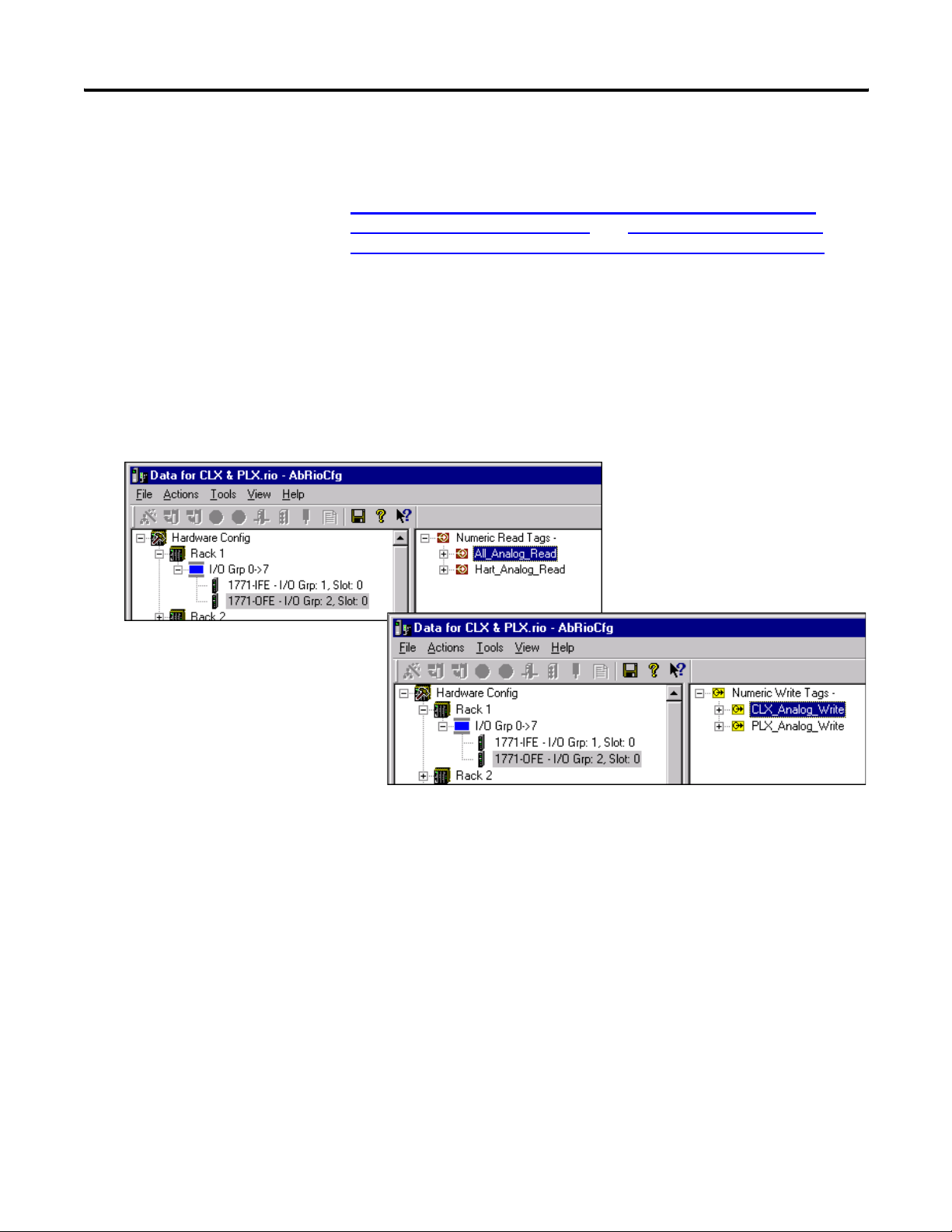
Block transfer read data can be mapped to numeric read tags.
Block transfer write data can be mapped to numeric write tags.
You cannot map individual registers; all the data for a rack or I/O
module is mapped to the tag. You can map data from many I/O
modules into the same tag.
Mappings must be unique. You cannot map a block transfer module
to more than one tag of the same type or to multiple locations within
the same tag.
In addition, block transfer modules have status information that can
be mapped to flag read tags. Refer to Supported 1771 Modules
page 83 for detailed information on status information.
on
Publication 1757-UM007D-EN-P - December 2008 31
Page 34

Chapter 2 Configure the 1757-ABRIO Module
I/O
To map I/O data to a tag, complete the following steps.
1. Expand the tag to show the tag elements.
2. Scroll to display the destination in the tag where you want to
add the data.
3. Drag the rack or block transfer module to the desired location in
the tag.
Deleting Mapped Data
To delete mapped data from a tag, complete the following steps.
Tips for Configuring Modules
1. Select any element of the data.
2. Click Delete.
You cannot delete individual elements of the data for an I/O module.
When you delete an element you delete all the data for the particular
module. Data is not affected for the other modules mapped to the
same tag.
Use the largest range of raw values possible for the 1757-ABRIO
module and optimum data resolution. The scaling should be done to
engineering units in the module.
The following operations are features of firmware version 2.1. To use
these features, you need the following:
Firmware version 2.1 or above for the 1757-ABRIO module
AbRioCfg software version 2.0 or above
AbRioCfg software version 2.0 or above can open or upload
configurations made with previous versions of AbRioCfg
software.
32 Publication 1757-UM007D-EN-P - December 2008
Page 35

Configure the 1757-ABRIO Module Chapter 2
Add Racks Offline
To add a rack, complete the following steps.
1. Right-click Hardware Config and select Add A Rack.
2. Enter the Rack Number (1 to 37 octal), Starting I/O Group
(0,2,4,6) and Ending I/O Group (1,3,5,7) and click OK.
Publication 1757-UM007D-EN-P - December 2008 33
Page 36

Chapter 2 Configure the 1757-ABRIO Module
Delete Racks Offline
To delete racks offline, complete the following steps.
1. Right-click the partial rack and select Delete Rack.
A warning dialog box opens.
2. Click OK.
When you delete a rack, all I/O modules on the rack and flag
mappings for the rack are deleted. If this partial rack is the only one in
the rack number, the rack number will be deleted from the tree.
34 Publication 1757-UM007D-EN-P - December 2008
Page 37

Configure the 1757-ABRIO Module Chapter 2
Change the Baud Rate Offline
To change the baud rate offline, complete the following steps.
1. Select Actions>Change Baud Rate.
The Select Baud Rate dialog box opens.
2. Select the desired baud rate and click OK.
A warning window opens
Download the Configuration
3. To select the path to the 1757-ABRIO module from an RSWho
window, click Yes.
To make this change in the offline file only, click No.
To download the configuration to the 1757-ABRIO module from
AbRioCfg software, select Actions>Download config or click the
Download Configuration to Module button on the toolbar.
WARNING
Downloading a configuration disrupts communication between
the 1757-ABRIO module and the RIO network.
If the module is in active or forced active mode, the
configuration program asks if you want to remove it from
active mode.
Scaling data for modules that have not been mapped to tags is
not downloaded with the configuration.
Publication 1757-UM007D-EN-P - December 2008 35
Page 38

Chapter 2 Configure the 1757-ABRIO Module
Upload the Configuration
To upload a configuration from a 1757-ABRIO module, select
Actions>Upload config or click the Upload Config From Module
button on the toolbar.
36 Publication 1757-UM007D-EN-P - December 2008
Page 39

Chapter
Creating Generic Modules in AbRioCfg
Software
3
Introduction
Generic Module Overview
This chapter describes using a generic module type which supports
any block transfer I/O module that uses 16-bit integer data. To use
these features, you need the following:
Firmware version 2.1 or above of the firmware for the
1757-ABRIO module
AbRioCfg software version 2.1 or above
AbRioCfg software version 2.1 or above can open or upload
configurations made with previous versions of AbRioCfg
software.
If you are using a 1771 module refer to Supported 1771 Modules
page 83.
If you need to access HART data refer to Accessing HART Data
page 115.
The generic module type makes it possible to do the following:
on
on
Configure and communicate with any block transfer I/O module
that uses 16-bit integer data. You create the configuration file as
a comma-separated variable (CSV) file, using a spreadsheet or
text editor, and import it using AbRioCfg software.
Configure a block transfer module that is already supported by
AbRioCfg software in ways that the standard configuration does
not allow, for example, using fewer channels than in the
standard module configuration, or adding features not
supported by the standard configuration.
Have up to 100 different generic module types in an
1757-ABRIO configuration file, and an unlimited number of
modules made from those 100 types.
37Publication 1757-UM007D-EN-P - December 2008 37
Page 40

Chapter 3 Creating Generic Modules in AbRioCfg Software
Generic Module Configuration File
The Generic Module configuration file consists of these sections.
– the configuration block transfer write (BTW)
– the data block transfer read
– the data block transfer write
Most configuration files have a configuration block transfer write.
Some may have both data block transfer read and data block transfer
write sections; others will have just one or the other. The maximum
size for each section is 64 words of data.
You can add comments to the file by preceding them with a
semicolon. Comments can be added to the end of an existing line or
can occupy separate lines. The configuration file can be created as a
text file or as a spreadsheet using a program like Excel and saved as a
CSV file.
IMPORTANT
To use a text file, separate the data fields with commas. To use a
spreadsheet, put the data values in separate columns.
The length of a CSV filename must not exceed 31 characters.
TIP
Sample configuration files are available for your use. The files
are located in the \GenProfile directory on the supplied
1757-ABRIO CD.
Configuration Block Transfer Write
The configuration block transfer write section (Config BTW) contains
the data that is sent to the module to set how it operates. The
configuration block transfer write is sent:
at powerup
when communication is restored after being lost
when the remote I/O network switches from program to run
The first line of the configuration block transfer write is the keyword
“configbtw”, followed by the block transfer length, in words.
EXAMPLE
configbtw, 13
This is followed by data definitions that consist of an offset and a
value.
38 Publication 1757-UM007D-EN-P - December 2008
Page 41

Creating Generic Modules in AbRioCfg Software Chapter 3
The offset is the offset into the block transfer and ranges from 0 to the
block transfer length - 1. For example, if the block transfer is 10 words
long, the allowed offsets range from 0 to 9.
The value can be in one of the following formats:
Format Range
Binary 0b0000000000000000 to 0b1111111111111111
Hexadecimal 0x0000 to 0xFFFF
Unsigned integer 0 to 65535
Signed integer -32768 to 32767
Binary values start with a leading “0b”. Hexadecimal values start with
a leading “0x”. It's usually easier and less prone to error to enter the
values in binary or hexadecimal.
TIP
EXAMPLE
If a module does not require a configuration block transfer
write, you can omit the Config BTW section of the configuration
file. For example, an SLC analog module does not require a
Config BTW section in the file.
0, 0b1011001100100001
7, 0xB321
11, 45857
Only non-zero values need be entered; all other values in the
configuration block transfer will default to 0.
Publication 1757-UM007D-EN-P - December 2008 39
Page 42

Chapter 3 Creating Generic Modules in AbRioCfg Software
Example: 1771-IFE Module
The following configuration block transfer write file configures a
1771-IFE for the following:
differential operation (8 input channels)
each channel set for 1-5 VDC or 4-20 mA
two's complement binary data format
each channel's raw data scaled between 0 and 4095
configbtw, 21 ; length 21
0, 0
1, 0
2, 0x0500 ; differential inputs, binary
3, 0
4, 0
5, 0
6, 0x4095 ; channel 1 scaling
7, 0
8, 0x4095 ; channel 2 scaling
9, 0
10, 0x4095 ; channel 3 scaling
11, 0
12, 0x4095 ; channel 4 scaling
13, 0
14, 0x4095 ; channel 5 scaling
15, 0
16, 0x4095 ; channel 6 scaling
17, 0
18, 0x4095 ; channel 7 scaling
19, 0
20, 0x4095 ; channel 8 scaling
Refer to the 1771-IFE module documentation for configuration details.
40 Publication 1757-UM007D-EN-P - December 2008
Page 43

Creating Generic Modules in AbRioCfg Software Chapter 3
Example: 1771-OFE module
The following configuration block transfer write file configures a
1771-OFE for:
binary data format
raw data from 0 to 0x0fff (0 to 4095 decimal) on each channel
configbtw, 13 ; length 13
4, 0x8000 ; binary data format
6, 0x0fff ; maximum raw value channel 1
8, 0x0fff ; maximum raw value channel 2
10, 0x0fff ; maximum raw value channel 3
12, 0x0fff ; maximum raw value channel 4
0 values have been omitted.
Refer to the 1771-OFE module documentation for the details.
Data Block Transfer Read
The data block transfer read defines the cyclic block transfer read that
is used to read data from an input module, and is sometimes used to
read status data from an output module.
The data block transfer read consists of a numeric section and a flag
section.
The beginning of the data block transfer read section is marked by the
keyword “databtr”, followed by the block transfer read length.
EXAMPLE
Numeric Data
The numeric section of the data block transfer read defines the I/O
data - its location, format, and scaling.
The beginning of the numeric section is marked by the keyword
“numeric”, followed by the number of values to be defined, and the
data format.
databtr, 15
Publication 1757-UM007D-EN-P - December 2008 41
Page 44

Chapter 3 Creating Generic Modules in AbRioCfg Software
AbRioCfg software checks the number of values to be defined against
the actual number of definitions and indicates an error if they do not
match.
The format can be one of:
Format Range of values
BCD 0 to 9999
Unsigned 0 to 65535
Integer -32768 to 32767
All items must have the same format.
EXAMPLE
numeric, 4, BCD
numeric, 8, integer
This is followed by definitions for the I/O data values, each on a row
of the spreadsheet (or line of a text file). Each definition consists of
the following fields:
Quantity Description
BTR offset Offset into BTR data The BTR offset is the offset into
the BTR data for the I/O data value
Underrange offset
(1)
Underrange bit Bit number, 0
Overrange offset
(1)
Overrange bit Bit number, 0
Polarity offset
(1)
Polarity bit Bit number, 0
Minimum raw value Minimum raw input
Maximum raw value Maximum raw input
Minimum scale value Minimum floating point scaled value that corresponds
Maximum scale value Maximum floating point scaled value that
(1)
If the offset is not used, the field must be left blank (not 0).
Word offset of underrange bit, 0–15
–15
Word offset of overrange bit, 0–15
–15
Word offset of polarity bit, 0–15
–15
to minimum raw value
corresponds to maximum raw value
Some modules have data underrange and overrange bits to indicate
out-of-range inputs.
If the underrange or overrange bit is set, the AbRioCfg software
sets the I/O value to NaN.
42 Publication 1757-UM007D-EN-P - December 2008
Page 45

Creating Generic Modules in AbRioCfg Software Chapter 3
If the module does not have overrange or underrange bits, leave
those fields blank in the configuration file.
Some modules have a separate polarity bit to indicate the sign of an
input.
If the polarity bit is set, the 1757-ABRIO module assigns the
corresponding data a negative value.
the 1757-ABRIO module uses the polarity offset and bit only for
the BCD data type. It ignores them for the other data types.
If the data type is BCD, enter the raw minimum and maximum values
in decimal, not hexadecimal. For example is the range is 0 to 9999,
enter the value as 9999, not 0x9999.
EXAMPLE
A 1771-IFE module has channel 1 data at offset 4, the
underrange bit is in offset 1, bit 0, the overrange bit is in offset
2, bit 0, and the polarity bit is in offset 3, bit 0. The raw data
ranges from 0 to 4095. We want to scale the raw data to
floating point values from 0 to 1000.
In a text file:
4,1, 0, 2, 0, 3, 0, 0, 4095, 0, 1000
In a spreadsheet:
numeric 4 BCD
41 020300409501000
Flag Data
In some cases the block transfer read contains data that we want to
map to flag read tags, for example, a module error bit. If a module has
flag data defined, you can then map it to flag read data in AbRioCfg
software.
The flag data section of the Data Block Transfer read defines the
location of this discrete data.
The beginning of the flag section is marked by a line containing the
keyword “flag”, followed by the total length of the flags data, in bits.
The length must be a multiple of 8.
EXAMPLE
flag, 32
This is followed by a number of lines that define where the flag data
is found. Each line consists of an offset and a length. The maximum
number of flag data definition lines is 4.
Publication 1757-UM007D-EN-P - December 2008 43
Page 46

Chapter 3 Creating Generic Modules in AbRioCfg Software
The offset is an offset into the block transfer. It can range from 0 to
the length of the block transfer - 1. If the offset is followed by an “H”,
it refers to the high byte of the block transfer word. The length can
range from 8 to 504 and must be a multiple of 8. The sum of the
lengths in the data definitions must match the length in the “flag” line.
EXAMPLE
flag, 32
0,8
2H,8
4,16
Example: 1771-IFE Module
The following definitions assign the underrange and overrange bits
from a 1771-IFE module to flag data.
flag, 32
1,16
2,16
Special Flag Read Data
In addition to any flag read data you define in the configuration file,
the Generic Module always has 8 bits of predefined flag read data.
This data is found at the beginning of the flag data for the module. It
consists of the following flags:
Bit Description
0 Good communication, set to 1 if the block transfer to the module is
updating, 0 otherwise.
1 BTR Raw underrange bit, set if the raw input to the module is less than the
defined raw minimum. The module sets the scaled input to NaN.
2 BTR raw overrange, set if the raw input to the module is greater than the
defined raw maximum. The module sets the scaled input to NaN.
3 Reserved
4 Reserved
5 BTW raw underrange, set if the calculated output value is less than the
defined raw minimum. The module clamps the output at the raw minimum.
6 BTW raw overrange, set if the calculated output value is greater than the
defined raw maximum. The module clamps the value at the raw maximum.
7 BTW NaN, set if the floating point value written from the host is NaN.
44 Publication 1757-UM007D-EN-P - December 2008
Page 47

Creating Generic Modules in AbRioCfg Software Chapter 3
Sample 1771-IFE Configuration File
configbtw, 21 ; length 21
2, 0x0500 ; differential inputs, binary
5, 0
6, 0x4095 ; channel 1 scaling
7, 0
8, 0x4095 ; channel 2 scaling
9, 0
10, 0x4095 ; channel 3 scaling
11, 0
12, 0x4095 ; channel 4 scaling
13, 0
14, 0x4095 ; channel 5 scaling
15, 0
16, 0x4095 ; channel 6 scaling
17, 0
18, 0x4095 ; channel 7 scaling
19, 0
20, 0x4095 ; channel 8 scaling
databtr, 12
numeric, 4, signed
4, 1, 0, 2, 0, 3, 0, 0, 4095, 0, 1000
5, 1, 0, 2, 0, 3, 0, 0, 4095, 0, 1000
6, 1, 0, 2, 0, 3, 0, 0, 4095, 0, 1000
7, 1, 0, 2, 0, 3, 0, 0, 4095, 0, 1000
8, 1, 0, 2, 0, 3, 0, 0, 4095, 0, 1000
9, 1, 0, 2, 0, 3, 0, 0, 4095, 0, 1000
10, 1, 0, 2, 0, 3, 0, 0, 4095, 0, 1000
11, 1, 0, 2, 0, 3, 0, 0, 4095, 0, 1000
flag, 32
1, 16
2, 16
Data Block Transfer Write
The data block transfer write defines the cyclic block transfer read that
is used to write data to an output module. The data block transfer
write consists of a numeric section and a flag section. The beginning
of the data block transfer write section is marked by the keyword
“databtw, followed by the block transfer write length.
EXAMPLE
Publication 1757-UM007D-EN-P - December 2008 45
databtw, 12
Page 48

Chapter 3 Creating Generic Modules in AbRioCfg Software
Numeric Data
The numeric section of the data block transfer write defines the I/O
data - its location, format, and scaling.
The beginning of the numeric section is marked by the keyword
“numeric”, the number of values to be defined, and the data format.
AbRioCfg software checks the number of values to be defined against
the actual number of definitions and indicates an error if they do not
match.
The format can be one of the following.
Format Range of values
BCD 0 to 9999
Unsigned 0 to 65535
Integer -32768 to 32767
All items must have the same format.
EXAMPLE
numeric, 4, BCD
numeric, 8, integer
This line is followed by definitions for the I/O data values, each on a
row of the spreadsheet (or line of a text file). Each definition consists
of the following fields:
Quantity Description
BTW offset Offset into BTW data
Polarity offset Word offset of polarity bit
Polarity bit Bit number, 0-15
Minimum raw value Minimum raw output
Maximum raw value Maximum raw output
Minimum scale value Minimum floating point scaled value that corresponds
to minimum raw value
Maximum scale value Maximum floating point scaled value that corresponds
to maximum raw value
The BTW offset is the offset into the BTW data for the I/O data value.
Some modules have a separate polarity bit to indicate the sign of an
input. If the data being written is negative, the 1757-ABRIO module
sets the polarity bit.
46 Publication 1757-UM007D-EN-P - December 2008
Page 49

Creating Generic Modules in AbRioCfg Software Chapter 3
The 1757-ABRIO module uses the polarity offset and bit only for the
BCD data type. It ignores them for the other data types.
TIP
If the data type is BCD, enter the raw minimum and maximum
values in decimal, not hexadecimal. For example is the range is
0 to 9999, enter the value as 9999, not 0x9999.
If the scaled valued written is NaN, the raw output gets set to the
corresponding value in the configuration data. For example, if an I/O
data value is at offset 7 in the data block transfer write, the value at
offset 7 in the configuration block transfer write is written if the host
controller writes NaN to the tag that is mapped to the I/O value.
EXAMPLE
A 1771-OFE module has channel 1 data at offset 0. The polarity
bit is offset 4 bit 0. We want to write floating point values from
0 to 1000 and have them scaled to the raw values 0 to 4095.
In a text file:
0, 4, 0, 0, 4095, 0, 1000
In a spreadsheet:
0 4 0 0 4095 0 1000
Flag Data
In some cases the block transfer write contains data that we want to
map to flag write tags.
The flag data section of the Data Block Transfer write defines the
location of this discrete data.
The beginning of the flag section is marked by a line containing the
keyword “flag”, followed by the total length of the flags data, in bits.
The length can be from 8 to 504 and must be a multiple of 8.
EXAMPLE
This is followed by a number of lines that define where the flag data
is found. Each line consists of an offset and a length. The maximum
number of flag definition lines is 4.
The offset is an offset into the block transfer. It can range from 0 to
the length of the block transfer - 1. If the offset is followed by an “H”,
it refers to the high byte of the block transfer word.
flag, 32
The length can range from 8 to 504 and must be a multiple of 8.
Publication 1757-UM007D-EN-P - December 2008 47
Page 50

Chapter 3 Creating Generic Modules in AbRioCfg Software
The sum of the lengths in the data definitions must match the length
in the “flag” line.
Creating a Generic Module in AbRioCfg software
EXAMPLE
flag, 32
0,8
2H,8
4,16
Example 1771-OFE Configuration File
configbtw, 13 ; length 13
4, 0x8000 ; binary data format
6, 0x0fff ; maximum raw value channel 1
8, 0x0fff ; maximum raw value channel 2
10, 0x0fff ; maximum raw value channel 3
12, 0x0fff ; maximum raw value channel 4
databtw, 12
numeric, 4
0, 4, 0, 0, 4095, 0, 1000
1, 4, 1, 0, 4095, 0, 1000
2, 4, 2, 0, 4095, 0, 1000
3, 4, 3, 0, 4095, 0, 1000
To add a generic module in AbRioCfg software, complete the
following steps.
1. Right-click the rack to which the module will be added and
select Add Module.
48 Publication 1757-UM007D-EN-P - December 2008
Page 51

Creating Generic Modules in AbRioCfg Software Chapter 3
2. Select a Module Type of Generic Module, the location for the
module and click OK.
3. Browse to or type the CSV file and path and click Import.
AbRioCfg software imports the configuration file and displays
the contents, or gives an error message if it finds problems with
the file.
4. Assign values for the BTR and BTW Update Times.
5. Click OK to accept the module.
You can now map the data to tags by dragging the Generic module to
the desired numeric read, numeric write, flag read or flag write tag.
To change the configuration, re-import the configuration. If the
generic module was mapped to tags, the mappings will be deleted
and must be reassigned.
Publication 1757-UM007D-EN-P - December 2008 49
Page 52

Chapter 3 Creating Generic Modules in AbRioCfg Software
You can export the generic module configuration by clicking the
Export button in the Generic Module dialog box. Since comments in
the original file are not imported (and therefore are not exported), it is
usually better to modify the original configuration file and save it with
a new name. Export may be useful if you upload a configuration that
contains a generic module from a 1757-ABRIO module and you do
not have the original file.
50 Publication 1757-UM007D-EN-P - December 2008
Page 53

Chapter
4
Configuring the ProcessLogix Controller to
Access Data on the 1757-ABRIO Module
Introduction
Modes of Operation
This chapter describes:
the operating modes of the 1757-ABRIO module.
how to access data on the module from a ProcessLogix
controller.
There are four modes of operation for the module.
CONFIG
INACTIVE (Program)
ACTIVE (Run)
FORCED ACTIVE
The mode of the 1757-ABRIO module determines the RIO network
mode.
Modes related to RIO network operations:
INACTIVE (Program) mode, digital inputs continue to update
but digital outputs and block transfers do not.
ACTIVE (Run) mode, digital inputs and outputs update, and
block transfers update.
CONFIG Mode
The module is in CONFIG mode while AbRioCfg software downloads
a configuration. CONFIG mode is largely invisible to the user unless
the configuration being downloaded is large. After downloading, the
software returns the module to INACTIVE mode.
51Publication 1757-UM007D-EN-P - December 2008 51
Page 54

Chapter 4 Configuring the ProcessLogix Controller to Access Data on the 1757-ABRIO Module
INACTIVE Mode
The module is in INACTIVE mode when it is not receiving messages
from either a host controller or via OPC/DDE. The module is also in
INACTIVE mode when it has not been put in FORCED ACTIVE mode
by AbRioCfg software.
When the module is in INACTIVE mode, the RIO network is placed in
program mode with input updates but no output updates. The
1757-ABRIO module must be in the INACTIVE mode to accept a
download.
ACTIVE Mode (Run)
The module is in ACTIVE mode when it receives a message from
either a host controller or from an OPC or DDE server. When the
module is in ACTIVE mode, the RIO network is in run mode.
The module is in ACTIVE mode as long as any tag is being updated.
Each tag has an associated time-out. The tag is considered to be
updating until the time-out expires. If all tags have timed out, the
1757-ABRIO module automatically switches to INACTIVE mode.
If you try to download a configuration when the module is in ACTIVE
mode, AbRioCfg software asks if you want to take the module out of
ACTIVE mode. If you click OK, AbRioCfg software changes the mode,
downloads the configuration, then puts the module in INACTIVE
mode.
FORCED ACTIVE Mode
The module is in FORCED ACTIVE mode when you set ACTIVE mode
from the AbRioCfg program. FORCED ACTIVE mode lets you send
and receive data without having to create messages in the module. It
is intended primarily for setting up and testing RIO networks.
If you try to download a configuration when the module is in
FORCED ACTIVE mode, AbRioCfg software asks if you want to take
the module out of ACTIVE mode. If you click OK, AbRioCfg software
changes the mode, downloads the configuration, then puts the
module in INACTIVE mode.
IMPORTANT
52 Publication 1757-UM007D-EN-P - December 2008
When the module is in FORCED ACTIVE mode, the RIO network
is in run mode.
Page 55

Configuring the ProcessLogix Controller to Access Data on the 1757-ABRIO Module Chapter 4
Configure the 1757-PLX52 Controller
To access tag data on the 1757-ABRIO module from a ProcessLogix
controller, use the REQNUMARRAY, REQFLAGARRAY and
REQTEXTARRAY Exchange Blocks with CIPREAD and CIPWRITE
commands to read and write tags.
Use Control Builder software to complete the following steps.
1. Select the Exchange Block from the Library in Control Builder.
2. Add the desired Exchange Block to the CM (Control Module) by
dragging it into the CM window.
– REQFLAGARRAY for flag data
– REQNUMARRAY for numeric data
– REQTEXTARRAY for text data
3. Expand the Exchange Block by double-clicking on it.
4. Select the Main tab.
5. Give the block a name and set the execution order.
6. Select either CIPREAD or CIPWRITE for the message command.
Publication 1757-UM007D-EN-P - December 2008 53
Page 56

Chapter 4 Configuring the ProcessLogix Controller to Access Data on the 1757-ABRIO Module
7. Set the number of values to be read or written.
a. Flag arrays, 512 max
b. Numeric arrays, 64 max
c. Text arrays, 64 max
Array Examples
Flag Arrays
Numeric Arrays
Text Arrays
8. Set the data type to be read or written.
a. Numeric arrays, set Data Type in Target Device to FLOAT32.
b. Text arrays, set the Number of String Values to 1 and the Char
Length of String Values to 64.
9. Select the Communications tab.
10. Set the Path from the ProcessLogix controller to the 1757-ABRIO
module.
See the tip on page 72
or Control Builder Help for information
on entering the path.
54 Publication 1757-UM007D-EN-P - December 2008
Page 57

Configuring the ProcessLogix Controller to Access Data on the 1757-ABRIO Module Chapter 4
11. Set the File Name in the Exchange Blocks to the names of the
tags you created in the 1757-ABRIO module.
12. Perform any other configuration required by your application on
the other tabs.
IMPORTANT
Be sure to expose the Error codes in your Exchange Blocks.
13. Click OK to accept the block.
14. Wire the ready flag (READYFL) to the send flag (SENDFL) for
each exchange block.
15. Download the CM to the ProcessLogix controller and activate it.
Publication 1757-UM007D-EN-P - December 2008 55
Page 58

Chapter 4 Configuring the ProcessLogix Controller to Access Data on the 1757-ABRIO Module
Live Data Examples
Double-click function block
56 Publication 1757-UM007D-EN-P - December 2008
Page 59

Chapter
5
Configuring RSLogix 5000 Software to Access
Data on the 1757-ABRIO Module
Introduction
Modes of Operation
This chapter describes:
the operating modes of the 1757-ABRIO module.
how to access data on the module from a ControlLogix
controller.
There are four modes of operation for the module.
CONFIG
INACTIVE (Program)
ACTIVE (Run)
FORCED ACTIVE
The mode of the 1757-ABRIO module determines the RIO network
mode.
Modes related to RIO network operations:
INACTIVE (Program) mode, digital inputs continue to update
but digital outputs and block transfers do not.
ACTIVE (Run) mode, digital inputs and outputs update, and
block transfers update.
CONFIG Mode
The module is in CONFIG mode while AbRioCfg software downloads
a configuration. CONFIG mode is largely invisible to the user unless
the configuration being downloaded is large. After downloading, the
software returns the module to INACTIVE mode.
57Publication 1757-UM007D-EN-P - December 2008 57
Page 60

Chapter 5 Configuring RSLogix 5000 Software to Access Data on the 1757-ABRIO Module
INACTIVE Mode
The module is in INACTIVE mode when it is not receiving messages
from either a host controller or via OPC/DDE. The module is also in
INACTIVE mode when it has not been put in FORCED ACTIVE mode
by AbRioCfg software.
When the module is in INACTIVE mode, the RIO network is placed in
program mode with input updates but no output updates. The
1757-ABRIO module must be in the INACTIVE mode to accept a
download.
When scheduled connections are used, the 1757-ABRIO module’s
mode will always follow the ControlLogix controller’s mode regardless
if it is receiving messages. For example, when the controller is in
PROGRAM mode, the module is in INACTIVE mode.
ACTIVE Mode (Run)
The module is in ACTIVE mode when it receives a message from
either a host controller or from an OPC or DDE server. When the
module is in ACTIVE mode, the RIO network is in run mode.
The module is in ACTIVE mode as long as any tag is being updated.
Each tag has an associated time-out. The tag is considered to be
updating until the time-out expires. If all tags have timed out, the
1757-ABRIO module automatically switches to INACTIVE mode.
If you try to download a configuration when the module is in ACTIVE
mode, AbRioCfg software asks if you want to take the module out of
ACTIVE mode. If you click OK, AbRioCfg software changes the mode,
downloads the configuration, then puts the module in INACTIVE
mode.
When scheduled connections are used, the 1757-ABRIO module’s
mode will always follow the ControlLogix controller’s mode regardless
if it is receiving messages. For example, when the controller is in RUN
mode, the module is in ACTIVE mode.
58 Publication 1757-UM007D-EN-P - December 2008
Page 61

Configuring RSLogix 5000 Software to Access Data on the 1757-ABRIO Module Chapter 5
FORCED ACTIVE Mode
The module is in FORCED ACTIVE mode when you set ACTIVE mode
from the AbRioCfg program. FORCED ACTIVE mode lets you send
and receive data without having to create messages in the module. It
is intended primarily for setting up and testing RIO networks.
If you try to download a configuration when the module is in
FORCED ACTIVE mode, AbRioCfg software asks if you want to take
the module out of ACTIVE mode. If you click OK, AbRioCfg software
changes the mode, downloads the configuration, then puts the
module in INACTIVE mode.
IMPORTANT
When the module is in FORCED ACTIVE mode, the RIO network
is in run mode.
Publication 1757-UM007D-EN-P - December 2008 59
Page 62

Chapter 5 Configuring RSLogix 5000 Software to Access Data on the 1757-ABRIO Module
Scheduled Digital I/O Connections in RSLogix 5000 Programs
1757-ABRIO module firmware versions 1.2 and above support
scheduled connections for exchanging digital input and output data
between the 1757-ABRIO module and the host ControlLogix
controller. This results in much faster updates for the digital data than
is possible using unscheduled messages. This section describes how
to configure the module and the format of the scheduled data.
When you add a 1757-ABRIO module to the I/O Configuration of an
RSLogix 5000 program using the generic 1757-MODULE profile, a data
connection is created for the digital remote I/O data. See Tag
Descriptions for Scheduled Data in RSLogix 5000 Software on
page 149 for more information about the status tag when using
ControlLogix. The status tag gives global status for digital data and
individual rack status.
TIP
In order to access any numeric read, numeric write, or text read
data from the ControlLogix controller you must also complete
Unscheduled I/O Connections in ControlLogix
on page 67.
Scheduled Connection Types
There are two types of scheduled connection.
Exclusive Owner, read/write
Input Only, read only
Setup an Exclusive-owner Connection
Configure a generic module profile in RSLogix 5000 software to
represent the 1757-ABRIO module. This dictates the format and
amount of scheduled data, and how often the scheduled data is
transferred. The ControlLogix controller is the owner of the
connection and controls the digital outputs. The connection is referred
to as an exclusive-owner connection.
IMPORTANT
In order for the scheduled connection to control the outputs of a
chassis, the chassis must not be mapped to any flag write tag
in the AbRioCfg software configuration that has been
downloaded to the 1757-ABRIO module.
60 Publication 1757-UM007D-EN-P - December 2008
Page 63

Configuring RSLogix 5000 Software to Access Data on the 1757-ABRIO Module Chapter 5
Remote I/O Operating Modes
If there is an exclusive-owner connection to the 1757-ABRIO module,
the module’s remote I/O mode (run or program) follows the owner
ControlLogix controller’s Run or Program mode. If the owner
ControlLogix controller is in Program mode, the 1757-ABRIO module
is in program mode (even if the module is receiving messages). If the
ControlLogix controller is in Remote Test mode, the remote I/O mode
for the 1757-ABRIO module is program.
The remote I/O mode is not affected by the operating mode of a
ControlLogix controller that has an input-only connection to the
1757-ABRIO module. In the absence of an exclusive-owner
connection, the 1757-ABRIO module’s remote I/O mode is determined
by whether it is receiving messages, as before.
Add a Module as an Exclusive-owner Connection
To configure the 1757-ABRIO module in RSLogix 5000 software, the
ControlLogix controller must be offline.
1. Create a new project for your type of controller.
2. Type a name for the controller, and select the slot it occupies in
the ControlLogix chassis.
3. Click OK.
4. Right-click on I/O configuration and select New Module.
5. Under Other, select the 1756-MODULE Generic 1756 Module
and click OK.
The Module Properties dialog box opens.
Publication 1757-UM007D-EN-P - December 2008 61
Page 64

Chapter 5 Configuring RSLogix 5000 Software to Access Data on the 1757-ABRIO Module
6. Type a Name and a Description for the module, if desired.
7. Set the Slot number for the module in the ControlLogix chassis.
8. For the Comm Format, select Data - INT - With Status.
9. Select the following values for the Connection Parameters.
Assembly
Instance
Input 1 250
Output 2 248
Configuration 4 0
Status Input 5 10
Status Output 6 N/A
Size
10. Verify that the Open Module Properties checkbox is checked
and click OK.
11. Set the module’s Requested Packet Interval (RPI).
This is how often the module's scheduled data is updated in the
controller. The value can range from 0.2 to 750 ms. The default
time is 5 ms.
12. Click OK.
13. Save the program and download it to the ControlLogix
controller.
62 Publication 1757-UM007D-EN-P - December 2008
Page 65

Configuring RSLogix 5000 Software to Access Data on the 1757-ABRIO Module Chapter 5
Output Priority
If a digital rack is mapped to a flag write tag in the AbRioCfg software,
the flag data takes precedence over the digital outputs in the
scheduled connection, even if nothing is writing to the flag write tag.
To control outputs on a chassis using a scheduled connection, make
sure the chassis is not mapped to a flag write tag.
Setup Input-only Connections
The 1757-ABRIO module also supports input-only connections. In a
ControlLogix system, multiple controllers can receive inputs from a
module, but only one controller can control the outputs. An
input-only connection does not require the presence of an exclusive
owner connection. More than one ControlLogix controller can open
an input-only connection to the 1757-ABRIO module and receive its
inputs.
Add a Module as an Input-only Connection
To configure an input-only connection to the 1757-ABRIO module in
RSLogix 5000 software, you must be offline.
1. Create a new project for your type of controller.
2. Type a name for the controller, and select the slot it occupies in
the ControlLogix chassis.
3. Click OK.
4. Right-click on I/O configuration and select New Module.
5. Under Other, select the 1756-MODULE Generic 1756 Module
and click OK.
Publication 1757-UM007D-EN-P - December 2008 63
Page 66

Chapter 5 Configuring RSLogix 5000 Software to Access Data on the 1757-ABRIO Module
The Module Properties dialog box opens.
6. Type a Name and a Description for the module, if desired.
7. Set the Slot number for the module in the ControlLogix chassis.
8. For the Comm Format, select Input Data - INT - With Status.
9. Select the following values for the Connection Parameters.
Assembly
Instance
Input 1 250
Output 3 N/A
Configuration 4 0
Status Input 5 10
Status Output 6 N/A
Size
64 Publication 1757-UM007D-EN-P - December 2008
Page 67

Configuring RSLogix 5000 Software to Access Data on the 1757-ABRIO Module Chapter 5
10. Verify that the Open Module Properties checkbox is checked
and click OK.
11. Set the module’s Requested Packet Interval.
This is how often the module's scheduled data is updated in the
controller. The value can range from 0.2 to 750 ms. The default
is 5 ms.
Publication 1757-UM007D-EN-P - December 2008 65
Page 68

Chapter 5 Configuring RSLogix 5000 Software to Access Data on the 1757-ABRIO Module
12. Click OK.
13. Save the program and download it to the ControlLogix
controller.
Click the 1757-ABRIO module to
display the new tags. See Tag
Descriptions for Scheduled Data in
RSLogix 5000 Software on
page 149 for details.
Live Data Example
66 Publication 1757-UM007D-EN-P - December 2008
Page 69

Configuring RSLogix 5000 Software to Access Data on the 1757-ABRIO Module Chapter 5
Unscheduled I/O Connections in ControlLogix
There are several tasks you need to complete before you can access
data from ControlLogix. You need to create the following:
Tags for messages
Tags for storage areas
Message commands to read RIO network data
Message commands to write RIO network data
Use RSLogix 5000 message instructions (MSG) to access tags on the
1757-ABRIO module. Refer to RSLogix 5000 Online Help and the
Logix5000 Controllers General Instructions Reference Manual,
publication 1756-RM003
Before you create the MSG instruction, create a tag of type MESSAGE
to act as a control for the MSG instruction. You must also create a
source (write) or destination (read) tag for the data written to or read
from the 1757-ABRIO module.
, for details on messages.
1. Create Tags For All Messages and All Storage Areas
RSLogix 5000 Example Tags in Program Mode
For message type,
select CIP Data
Table Read or
Data Table Write.
On a Read, the
source is a
1757-ABRIO Tag
Name. The
Destination, on a
Read, is an
RSLogix 5000 Tag
Name.
These are the tags
you will reference
in your message
commands.
Publication 1757-UM007D-EN-P - December 2008 67
Page 70

Chapter 5 Configuring RSLogix 5000 Software to Access Data on the 1757-ABRIO Module
2. Create Message Commands to Read and Write All RIO Network Data
RSLogix 5000 Example Message Commands in Program Mode
Use the Browse
button ( ) to
locate the
read/write tags
you want to
reference in your
message
commands. See
Create a Tag
on
page 30 for more
information.
This table shows the source (write) or destination (read) data type to
use with each 1757-ABRIO tag type and the size for each type.
ControlLogix Data types
1757-ABRIO Tag Source/destination Type Storage Data Size
Numeric read REAL 64
Numeric write REAL 64
Flag read DINT 16
Flag Write DINT 16
Text read SINT 64
68 Publication 1757-UM007D-EN-P - December 2008
Page 71

Configuring RSLogix 5000 Software to Access Data on the 1757-ABRIO Module Chapter 5
Use the following steps to add the MSG instruction.
WARNING
The EN_CC bit in a ControlLogix MESSAGE tag defaults to on. If
the message executes successfully even once, it gets retried
periodically, even if the ladder logic has disabled the message.
If you want to keep the connection open no matter what, turn
on the bit.
Turn off the EN_CC bit in any ControlLogix MESSAGE tag you
use in a MSG instruction to access data on the 1757-ABRIO
module.
1. Add the MSG instruction to the ladder logic, along with
whatever logic you want to use to cause the instruction to
execute.
2. Open the Message Configuration dialog box by clicking the
button in the instruction.
3. Select the Message Type.
The Message type should be either CIP Data Table Read to read
a tag from the 1757-ABRIO module or CIP Data Table Write to
write a tag to the 1757-ABRIO module.
Publication 1757-UM007D-EN-P - December 2008 69
Page 72

Chapter 5 Configuring RSLogix 5000 Software to Access Data on the 1757-ABRIO Module
4. Select the Source Element.
If you are writing to the 1757-ABRIO module, this is the
ControlLogix controller tag.
If you are reading from the 1757-ABRIO module, this is the
name of the tag in the 1757-ABRIO module.
TIP
IMPORTANT
Use this tag To
All_Analog_Read Read data from input modules.
The tag is listed under Numeric Read Tags.
All_Flag_Read[100] Flag read for status and digital data.
This is the message needed to get to analog
data.
If you are reading flag read tags using a ControlLogix controller,
you must append [100] to the 1757-ABRIO tag name. This tells
the 1757-ABRIO module that the message is coming from a
ControlLogix controller.
The 1757-ABRIO module must return different data types to
ProcessLogix and ControlLogix controllers. For example, to read
a tag with name FlagRead, you would create a MSG instruction
with Source Element set to FlagRead[100].
5. Type the Number of Elements.
This is usually the number from the table on page 68
. You can
select a size smaller than the maximum if not all of the elements
in the 1757-ABRIO module tag have been mapped.
6. Select the Destination Element.
70 Publication 1757-UM007D-EN-P - December 2008
Page 73

Configuring RSLogix 5000 Software to Access Data on the 1757-ABRIO Module Chapter 5
7. Select the Communication tab.
8. Type the path from the ControlLogix controller to the
1757-ABRIO module.
Publication 1757-UM007D-EN-P - December 2008 71
Page 74

Chapter 5 Configuring RSLogix 5000 Software to Access Data on the 1757-ABRIO Module
When you are using scheduled connections in ControlLogix this
is automatically populated with your 1757-ABRIO module’s
name and address through an RSNetworx network polling.
TIP
Illustrated is the path from the
ProcessLogix or the ControlLogix
controller to the remote 1757-ABRIO
module.
Path = 1,4,2,20,1,2
1: From the backplane
4: Node, 1756-CNBR Module in slot 4
TIP
The 1757-ABRIO module, ProcessLogix controller and
ControlLogix controller (most likely) will not be in the same
racks. Refer to RSLogix 5000 Online Help and the Logix5000
Controllers General Instructions Reference Manual, publication
1756-RM003
for details on MSG paths.
If you need to manually input the communications path to a module, follow this
general example of how to find the path to the rack.
2: Path out of the CNBR, ControlNet
20: MAC ID of the target CNBR in the remote rack
1: From the CNBR, via the backplane
2:Slot location of the 1757-ABRIO module
9. Click OK to accept the MSG instruction.
10. After all message instructions are configured, save the program
and download it to the ControlLogix controller.
72 Publication 1757-UM007D-EN-P - December 2008
Page 75

Configuring RSLogix 5000 Software to Access Data on the 1757-ABRIO Module Chapter 5
Live Data Example
Publication 1757-UM007D-EN-P - December 2008 73
Page 76

Chapter 5 Configuring RSLogix 5000 Software to Access Data on the 1757-ABRIO Module
Ladder Rung Example
74 Publication 1757-UM007D-EN-P - December 2008
Page 77

Chapter
6
Accessing Data through a DDE or OPC Server
Introduction
Accessing Data from a DDE or OPC Server
This chapter describes how to access data on the module using a DDE
or OPC Server.
You can access data on the 1757-ABRIO module directly using a DDE
or OPC server such as RSLinx software, without the intervention of a
host controller.
Configuring a Topic in RSLinx Software
Use the following procedure to use RSLinx software as a DDE or OPC
server to access data on the 1757-ABRIO module.
1. Start RSLinx software
2. Select DDE/OPC Topic Configuration from the main menu.
3. Click New to create a new DDE or OPC topic, and give the topic
a name.
4. Select the Data Source tab and browse to the 1757-ABRIO
module.
5. Select the Data Collection tab.
6. Set the Processor Type to Logix5000.
7. Check Polled Messages and set the poll period to an appropriate
value.
8. Un-check Unsolicited Messages.
9. Leave the remaining values at their default values and click
Apply.
10. Select the Advanced Communication tab.
11. Select the Communications Driver you are using.
75Publication 1757-UM007D-EN-P - December 2008 75
Page 78

Chapter 6 Accessing Data through a DDE or OPC Server
12. Change Local or Remote Addressing defaults to Local.
13. Click Done to accept the DDE/OPC topic.
Accessing the Data
1. Start your DDE or OPC client.
2. Connect to RSLinx software.
If you are using a bridge device to communicate with the
1757-ABRIO module, select Remote and configure the bridging.
Refer to the RSLinx software documentation for detailed
information on how to configure bridging.
The 1757-ABRIO module supports browsing of tags.
3. Type or browse to the tags you want to monitor in the client.
76 Publication 1757-UM007D-EN-P - December 2008
Page 79

Chapter
Monitoring the 1757-ABRIO Module
7
Introduction
Monitoring the Operation
This chapter provides the following information on:
monitoring the operation of the 1757-ABRIO module.
monitoring the data value of tags.
monitoring the status of a block transfer.
monitoring the scanner log.
recognizing and clearing fatal errors.
The AbRioCfg software lets you monitor the operation of the module
and perform maintenance operations. Tag, block transfer, and module
diagnostic counters are available only from AbRioCfg software, and
are not available to a ProcessLogix or ControlLogix controller.
AbRioCfg software can be used to:
display the current values of the digital inputs and outputs.
display the current values of block transfer data, along with
diagnostic information on the block transfer.
display the current contents of a tag.
display the module log, which consists of messages from the
firmware running on the module.
clear the log.
copy the contents of the log to the clipboard for use by another
application. This is often useful for technical support.
clear fatal errors and dump the fatal error log to a file for use by
technical support.
Monitoring Digital I/O
77Publication 1757-UM007D-EN-P - December 2008 77
To monitor the current value of digital inputs or digital outputs on all
racks, select Tools>Monitor Inputs or Tools>Monitor Outputs.
Rows correspond to racks 1 to 37 octal; columns correspond
to I/O groups 0 to 7.
Data can be displayed in hexadecimal, signed decimal, or
unsigned decimal using the View menu or buttons on the
toolbar. The default format is hexadecimal. One hexadecimal
digit corresponds to 4 digital bits.
You can use the monitor program to edit data.
Page 80

Chapter 7 Monitoring the 1757-ABRIO Module
Use the Edit>Write toolbar button or the menu item to enable editing.
You can now change any data and it will be written to the network
(outputs) or to the data table (inputs). However if the same data is
being updated by I/O modules or the controller, the value you write is
overwritten the next time this I/O module is scanned.
Monitoring the Data Value of Tags
To monitor the current data value in a tag, complete the following
steps.
1. Select the corresponding tab for the data type of the tag you
want to monitor (Numeric read, etc.).
2. Select the tag you want to monitor.
3. Right-click the tag and select Monitor Tag.
The tag monitor displays the raw data for the tag, as well as
diagnostic data.
The raw data can be displayed as floating point, hexadecimal, signed,
or unsigned integer.
Refer to the following table for tag diagnostic information.
Tag Diagnostic Counters
Counter Description
Tag Name
Command Read or write
Type Numeric, flag or text
The tag name in
AbRioCfg software
MsgNum 0 to 63, used internally by the 1757-ABRIO module
Len Tag length, units are bytes for flag and text tags, floats for
numeric tags
Req count Number of updates this tag has been accessed (read or written)
Avg Req Time Average update time for this tag, in ms. This is the average of
the previous 64 updates.
Min Req Time Minimum request time for this tag, in ms
Max Req Time Maximum update time for this tag, in ms
Time out The message time-out, in ms
Status Active or Inactive
To clear the diagnostic counters, select Actions>ClearDiagCounters or
click the Clear Diag Counters button on the toolbar.
78 Publication 1757-UM007D-EN-P - December 2008
Page 81

Monitoring the 1757-ABRIO Module Chapter 7
If you attempt to monitor a tag that has not been downloaded to the
1757-ABRIO module, AbRioCfg software displays a message that
indicates there is a configuration mismatch between the configuration
in AbRioCfg software and the configuration in the 1757-ABRIO
module.
Monitoring the Status of a Block Transfer
TIP
Use the same procedure to monitor digital and text data.
To monitor the current status of a block transfer, complete the
following steps.
1. Expand the chassis where the block transfer module you want
to monitor is located.
2. Select the module you want to monitor.
3. Right-click the module to highlight and select Monitor BT from
the menu.
The block transfer monitor displays the raw data for the block transfer
and some diagnostic information. For input modules there is both a
block transfer read and a block transfer write. The write consists of
configuration data.
The raw data can be displayed as hexadecimal, signed, or unsigned
integer. The default for block transfer data is hexadecimal.
Refer to the following table for diagnostic information on block
transfer reads.
Block Transfer Read Diagnostics
Counter Description
State Active/Inactive
Type Module type
BTR Len Block transfer read length
Req Update Time Requested update time in the module configuration, in ms
Avg Update Time Average update time for this block transfer read, in ms. This
is the average of the previous 8 updates.
Min Update Time Minimum update time for this block transfer read, in ms
Max Update Time Maximum update time for this block transfer read, in ms
Update Count Running count of updates for this block transfer read
Publication 1757-UM007D-EN-P - December 2008 79
Page 82

Chapter 7 Monitoring the 1757-ABRIO Module
Block Transfer Read Diagnostics
Counter Description
Ignored Req Running count of update requests ignored by the block
transfer module.
Prot Errors Running count of protocol errors for this block transfer read.
If this counter is incrementing, the module isn't responding
correctly. Possible causes are length mismatch, invalid reply.
Request Count Count of the number of times on successive scans this block
transfer was requested. If this is consistently a high number,
increase the requested update time - the module cannot
respond quickly enough at the current requested time. The
counter applies to both the BTR and BTW for this module.
Refer to the following table for block transfer write diagnostics.
Block Transfer Write Diagnostic Data
Counter Description
Monitoring the Scanner Log
The scanner log displays messages from the 1757-ABRIO firmware,
showing its normal operation and error messages. It may be useful in
tracking down errors and for Technical Support.
To monitor the scanner log, select Tools>Monitor Scanner Log.
To clear the scanner log, select Edit>ClearLog or click the Clear Log
button.
CFG len Length of the configuration data for this module.
BTW data len data length
Req Update Time Requested update time in module configuration, in ms.
Avg Update Time Average update time for this block transfer write, in ms. This
is the average of the previous 8 updates.
Min Update Time Minimum update time for this block transfer write, in ms.
Max Update Time Maximum update time for this block transfer write, in ms.
Update Count Running count of updates for this block transfer write.
Ignored Req Running count of update requests ignored by the destination
module for this block transfer write.
Prot Errs Running count of protocol errors for this block transfer write.
To copy the contents of the log to the Windows clipboard for use in
another application, select Edit>Copy or click Select All then the Copy
button.
80 Publication 1757-UM007D-EN-P - December 2008
Page 83

Monitoring the 1757-ABRIO Module Chapter 7
Monitoring Diagnostic Counters
The 1757-ABRIO module maintains diagnostic counters that indicate
the state of communication on the entire RIO network, as well as
counters related to each chassis. It also maintains an active rack list.
To monitor the diagnostic counters, select Tools>Monitor Diagnostic
Counters or click the Start the Diagnostics Counters Monitor button.
Active Rack List
The active rack list shows where the racks are located. If the bit is set
there is a rack at that rack number and starting I/O group. It does not
show the rack size.
The rows represent starting I/O groups. The columns represent the
rack numbers.
Global Diagnostic Counters
The global diagnostic counters consist of the following.
Global Diagnostic Counters
Counter Description
Tx This counter increments each time the 1757-ABRIO module transmits a
packet.
RxGood This counter increments when the 1757-ABRIO module receives a good
packet.
RxTout This counter increments when the 1757-ABRIO module sends a packet
but does not receive a reply.
RxBadCRC This counter increments when the 1757-ABRIO module receives a
packet with a bad CRC. Check cabling and termination on the RIO
network.
RxNoise This counter increments when the 1757-ABRIO module hears a carrier
without receiving a packet. Check cabling and termination on the RIO
network.
RxAbort This counter increments when the 1757-ABRIO module receives an
opening flag, then the packet ends without a closing flag.
PrtclErr This counter increments when the 1757-ABRIO module receives a
packet that makes no sense in terms of the protocol.
UpdAvg Average update time for all configured racks. This is the average of the
previous 64 updates.
UpdMin Minimum update time for all configured racks.
UpdMax Maximum update time for all configured racks.
Publication 1757-UM007D-EN-P - December 2008 81
Page 84

Chapter 7 Monitoring the 1757-ABRIO Module
The rack diagnostic counters consist of the following counters for
each partial rack.
Rack Diagnostic Counters
Counter Description
Rx This counter increments when the 1757-ABRIO module receives a
packet from this rack.
Crc This counter increments when the 1757-ABRIO module receives a
packet with a bad CRC from this rack.
Tout This counter increments when the 1757-ABRIO module sends a packet
to this rack and does not receive a reply within the time-out period.
Prtcl This counter increments when the 1757-ABRIO module receives a
packet from this rack that does not make sense in terms of the
protocol.
Fatal Errors
Fatal errors occur when the firmware on the module encounters an
unexpected condition. The module stops scanning, turns all three
status indicators red, displays the fatal error number on the 4-character
display, and stores a fatal error log that indicates the cause of the fatal
error.
To clear the fatal error and capture the fatal error log:
1. Cycle power to the module.
The 4-character display should show “FatalErrorCapture
required”.
2. Start AbRioCfg software.
3. Select Tools>Fatal Error Capture.
4. Store the fatal error log to a file.
This also clears the fatal error on the module.
5. Contact Rockwell Automation Technical Support and provide
them with the fatal error log, which will help diagnose the cause
of the problem.
Clearing fatal errors also clears the configuration on the module. After
you clear the fatal error, download the configuration to the module
using AbRioCfg software.
82 Publication 1757-UM007D-EN-P - December 2008
Page 85

Supported 1771 Modules
Chapter
8
Introduction
Module Description
This chapter:
lists the supported 1771 modules.
describes module configuration, I/O Data, and diagnostic data.
The 1757-ABRIO module supports all digital 1771 modules and the
following 1771 block transfer modules. For information on how to
communicate with other block transfer I/O modules, see Creating
Generic Modules in AbRioCfg Software on page 37.
Refer to the corresponding pages in this chapter for information about
configuring these modules with the 1757-ABRIO module.
Supported modules
Module Description Page
1771-IFE Analog input module 84
1771-OFE Analog output module 89
1771-IR RTD input module 92
1771-IXE Thermocouple/millivolt module 95
1771-IL Analog input module 98
1771-NOC High resolution current output module 101
1771-NIV High resolution voltage input module 107
1771-NOV High resolution voltage output module 104
1771-NR RTD input module 110
The AbRioCfg software handles the details of module configuration
using the parameters you supply. For applicable modules, the
1757-ABRIO module scales the raw data to floating point values using
optimal data resolution on the I/O module.
83Publication 1757-UM007D-EN-P - December 2008 83
Page 86

Chapter 8 Supported 1771 Modules
Refer to the following publications for information on installing and
using the supported modules.
I/O Module Documentation
Module Installation Instructions User Manual
1771-ASB NA 1771-UM001
1771-IFE 1771-5.45 1771-6.5.90
1771-6.5.115
1771-OFE 1771-IN044 1771-6.5.30
1771-IR 1771-5.63 1771-6.5.76
1771-IXE 1771-5.64 1771-6.5.130
1771-IL 1771-5.62 1771-6.5.91
1771-NOC NA 1771-UM127
1771-NIV NA 1771-UM127
1771-NOV NA 1771-UM127
1771-NR NA 1771-UM127
1771-IFE Module
1770-HT1 NA 1770-6.5.19
The 1771-IFE module is a 12-bit analog input module that can be
configured as 16 single-ended inputs or 8 differential inputs. Each
channel can be configured as one of the following.
IFE Channel Configurations
1 to 5 VDC 4 to 20 mA
0 to 5 VDC 0 to 20 mA
-5 to 5 VDC -20 to 20 mA
-10 to 10 VDC
Select between current or voltage by using jumpers on the module.
Select the range when you configure the 1771-IFE module in
AbRioCfg software.
84 Publication 1757-UM007D-EN-P - December 2008
Page 87

Supported 1771 Modules Chapter 8
Module Configuration
Configuring the 1771-IFE module consists of setting the following:
single-ended or differential operation
range and scaling for each channel
digital filter and time constant
real time sampling and time constant
module update time
When you add a 1771-IFE module to a rack, the 1771-IFE Module
dialog box opens.
Publication 1757-UM007D-EN-P - December 2008 85
Page 88

Chapter 8 Supported 1771 Modules
To configure the 1771-IFE module, complete the following steps.
1. Set the Input Type to single-ended or differential operation.
2. For each channel select the voltage or current range and enter
the scaling values.
The low scaling value corresponds to the minimum input
voltage or current; the high scaling value corresponds to the
maximum voltage or current.
For example, if the scaling values are 10.0 and 22.5 and the
range is configured for 0 to 5V dc, an input of 0V dc produces a
scaled input value of 10.0 and an input of 5V dc produces a
scaled input of 22.5. The range of scaling values is -3.4e38 to
3.4e38.
3. If desired, enable digital filtering and set the digital filtering time
constant.
If digital filtering is enabled, it applies to all channels. The digital
filtering time constant can range from 0.01 to .99 seconds.
4. If desired, enable real-time sampling.
If real-time sampling is enabled, the sampling rate is set for the
data and overrides the Update Time. The real-time sampling
period can range from 0.1 to 3.1 seconds.
5. Type the Update Time.
The Update Time is the rate at which the block transfer read,
which reads the data from the 1771-IFE module, executes. The
range of values is 1 to 16382 ms. This sets the requested update
rate, the actual rate depends on the baud rate, the number of
racks on the RIO network and whether block transfers are
running to other modules in the same rack.
6. Click OK to accept the configuration.
If you edit an existing 1771-IFE module and change the module
between single-ended and differential, any existing mappings for the
module will be deleted.
86 Publication 1757-UM007D-EN-P - December 2008
Page 89

Supported 1771 Modules Chapter 8
I/O Data
The 1771-IFE module returns the 8 or 16 words of floating point data
to the host controller, depending on whether the module is
configured for single-ended or differential operation.
IFE I/O Data
Numeric Offset Description
0 Channel 1 data
1 Channel 2 data
2 Channel 3 data
3 Channel 4 data
4 Channel 5 data
5 Channel 6 data
6 Channel 7 data
7 Channel 8 data
8 Channel 9 data (if applicable)
9 Channel 10 data (if applicable)
10 Channel 11 data (if applicable)
11 Channel 12 data (if applicable)
12 Channel 13 data (if applicable)
13 Channel 14 data (if applicable)
14 Channel 15 data (if applicable)
15 Channel 16 data (if applicable)
Map this data to a numeric read tag.
Diagnostic Data
The 1771-IFE module has 40-bits of diagnostic data that can be
mapped to a flag read tag.
IFE Diagnostic Data
Bit Description
0 Module good communication
8 Channel 1 underrange
9 Channel 2 underrange
10 Channel 3 underrange
11 Channel 4 underrange
Publication 1757-UM007D-EN-P - December 2008 87
Page 90

Chapter 8 Supported 1771 Modules
IFE Diagnostic Data
Bit Description
12 Channel 5 underrange
13 Channel 6 underrange
14 Channel 7 underrange
15 Channel 8 underrange
16 Channel 9 underrange
17 Channel 10 underrange
18 Channel 11 underrange
19 Channel 12 underrange
20 Channel 13 underrange
21 Channel 14 underrange
22 Channel 15 underrange
23 Channel 16 underrange
24 Channel 1 overrange
25 Channel 2 overrange
26 Channel 3 overrange
27 Channel 4 overrange
28 Channel 5 overrange
29 Channel 6 overrange
30 Channel 7 overrange
31 Channel 8 overrange
32 Channel 9 overrange
33 Channel 10 overrange
34 Channel 11 overrange
35 Channel 12 overrange
36 Channel 13 overrange
37 Channel 14 overrange
38 Channel 15 overrange
39 Channel 16 overrange
The Good Communication bit is set when the 1757-ABRIO module is
successfully communicating with the 1771-IFE module, and is 0
otherwise.
The underrange and overrange bits are set when the raw input for a
channel is outside the configured voltage or current range.
88 Publication 1757-UM007D-EN-P - December 2008
Page 91

Supported 1771 Modules Chapter 8
1771-OFE Module
The 1771-OFE module is a four-channel analog output module. The
module is available in three different types.
The 1771-OFE1 module has jumper-selectable voltage ranges.
The 1771-OFE2 module is a 4 to 20 mA current module.
The 1771-OFE3 module is a 0 to 50 mA current module.
The 1771-OFE1 module supports ranges of 1 to 5V dc, 0 to 10V dc
and -10 to 10V dc.
Module Configuration
When you add a 1771-OFE module to a rack, the 1771-OFE Module
dialog box opens.
To configure a 1771-OFE module, complete the following steps
1. Select the Module Type, either OFE1, OFE2 or OFE3.
Publication 1757-UM007D-EN-P - December 2008 89
Page 92

Chapter 8 Supported 1771 Modules
2. For each channel select the range for each channel and enter the
scaling values.
The low scaling value corresponds to the minimum output
voltage or current; the high scaling value corresponds to the
maximum output voltage or current.
EXAMPLE
If the scaling values are 10.0 and 22.5 and the range is
configured for 0 to 5V dc, a value of 10.0 produces an output of
0V dc and a value of 22.5 produces an output of 5V dc. The
range of scaling values is -3.4e38 to 3.4e38.
Values received from a controller that are outside the scaled
range are clamped to the scaled range value.
3. Set the LAST STATE jumper setting to match the jumpers on the
1771-OFE module.
The setting can be Last, Min, Mid, or Max. This value determines
how the 1757-ABRIO module responds to a loss of
communication with the host controller.
4. Set the Update Time.
The Update Time is the rate at which the block transfer write,
which writes data to the 1771-OFE module, occurs. The range of
values is from 1 to 16382 ms. This sets the requested update
rate; the actual rate depends on the baud rate, the number of
racks on the RIO network and whether block transfers are
running to other modules in the same rack.
5. Click OK to accept the module configuration.
I/O Data
4 words of floating point data are written to the 1771-OFE module.
1771-OFE I/O Data
Data Word Description
0 Channel 1 data
1 Channel 2 data
2 Channel 3 data
3 Channel 4 data
You map this data to a numeric write tag.
90 Publication 1757-UM007D-EN-P - December 2008
Page 93

Supported 1771 Modules Chapter 8
Diagnostic Data
The 1771-OFE module has 8 bits of diagnostic data that can be
mapped to a flag read tag.
OFE Diagnostic Data
Bit Description
0 OFE good communication bit
1 reserved
2 reserved
3 reserved
4 Channel 1 data invalid bit
5 Channel 2 data invalid bit
6 Channel 3 data invalid bit
7 Channel 4 data invalid bit
The good communication bit is set if the 1757-ABRIO module is
successfully communicating with the 1771-OFE module.
The data invalid bits are set if the value written to the channel is
outside the range of the scaling values entered in the configuration
dialog.
Publication 1757-UM007D-EN-P - December 2008 91
Page 94

Chapter 8 Supported 1771 Modules
1771-IR Module
The 1771-IR module is a 6-channel RTD module. Supported RTDs
include 100-ohm platinum and 10-ohm copper. You can use any other
type but the results are returned in ohms.
Module Configuration
When you add a 1771-IR module to a rack, the 1771-IR Module dialog
box displays.
92 Publication 1757-UM007D-EN-P - December 2008
Page 95

Supported 1771 Modules Chapter 8
To configure the 1771-IR module, complete the following steps.
1. Set the global RTD type to either 10-ohm copper or 100-ohm
platinum. If the RTD you are using is neither of these two, you
will override each channel to report the results in ohms.
2. If the RTD type is set to 10-ohm copper, enter the resistance
value at 25 C.
3. Select the Units of measurement, either degrees Fahrenheit or
Celsius, or Ohms.
4. If Ohms is the selected unit of measurement, select a resolution
of 10 M per count or 30 M per count.
5. For each channel, set the bias, gain and offset.
Refer to the RTD Input Module User Manual, publication
1771-6.5.129
, for more information.
6. If you want any of the channel results to be returned in Ohms,
check the Channel Units Override box for that channel.
7. If you want to use real-time sampling (RTS), check the RTS Rate
Enabled box and select the sampling rate from 0.1 to 3.1
seconds.
8. Type the module Update Time.
The Update Rate is the rate at which the block transfer read,
which reads the data from the 1771-IR module, occurs. The
range of values is 1 to 16382 ms. This sets the requested update
rate; the actual rate depends on the baud rate, the number of
racks on the RIO network and whether block transfers are
running to other modules in the same rack.
9. Click OK to accept the values.
Publication 1757-UM007D-EN-P - December 2008 93
Page 96

Chapter 8 Supported 1771 Modules
I/O Data
The 1771-IR module returns 6 words of floating point data to the host
controller.
1771-IR Module I/O Data
Data Word Description
0 Channel 1 data
1 Channel 2 data
2 Channel 3 data
3 Channel 4 data
4 Channel 5 data
5 Channel 6 data
This data is mapped to a numeric read tag.
Diagnostic Data
The 1771-IR module returns 16 bits of diagnostic data to the host
controller.
1771-IR Module Diagnostic Data
Data Bit Description
0 Module good communication
1 Channel 1 underrange
2 Channel 2 underrange
3 Channel 3 underrange
4 Channel 4 underrange
5 Channel 5 underrange
6 Channel 6 underrange
7 reserved
8 Channel 1 overrange
9 Channel 2 overrange
10 Channel 3 overrange
11 Channel 4 overrange
12 Channel 5 overrange
13 Channel 6 overrange
14 reserved
15 reserved
This data can be mapped to a flag read tag.
94 Publication 1757-UM007D-EN-P - December 2008
Page 97

Supported 1771 Modules Chapter 8
1771-IXE Module
The 1771-IXE module is an 8-channel thermocouple input module.
The channels are configured in groups of four. The module supports
types E, J, K, T, R and S thermocouples.
The module can also be used as a millivolt input module. The range is
from -100 to 100 mV.
Module Configuration
When you add a 1771-IXE module to a rack, the 1771-IXE Module
dialog box displays.
To configure the 1771-IXE module, complete the following steps.
1. Select the thermocouple type for each of the two groups of
channels, either one of the supported thermocouple types or
millivolts.
2. Set the units of measurement, either degrees Fahrenheit or
Celsius.
If you have selected millivolts for the returned data, this entry is
ignored.
Publication 1757-UM007D-EN-P - December 2008 95
Page 98

Chapter 8 Supported 1771 Modules
3. Set the gain and offset for each channel.
See the Thermocouple/Millivolt Input Module User Manual,
publication 1771-6.5.130
, for more information.
4. If desired, enable real-time sampling (RTS) and set the sampling
rate, from 0.1 to 3.1 seconds.
This becomes the effective data update rate and may override
the update rate if the update rate is smaller.
5. Set the Update Time for the module’s block transfer.
The range is 1 to 16382 milliseconds. This sets the requested
update rate; the actual rate depends on the baud rate, the
number of racks on the RIO network and whether block
transfers are running to other modules in the same rack.
I/O Data
The 1771-IXE module returns 9 words of floating point data.
1771-IXE Module I/O Data
Data Word Description
0 Channel 1 data
1 Channel 2 data
2 Channel 3 data
3 Channel 4 data
4 Channel 5 data
5 Channel 6 data
6 Channel 7 data
7 Channel 8 data
8 Cold junction temperature
This data can be mapped to a numeric read tag.
96 Publication 1757-UM007D-EN-P - December 2008
Page 99

Supported 1771 Modules Chapter 8
Diagnostic Data
The 1771-IXE module returns 24 bits of diagnostic data.
1771-IXE Module Diagnostic Data
Bit Description
0 Module good communication
1 Out of range
2 RTS time-out
3 reserved
4 Low cold junction temperature
5 High cold junction temperature
6 reserved
7 Calibration EEPROM failed
8 Channel 1 underrange
9 Channel 2 underrange
10 Channel 3 underrange
11 Channel 4 underrange
12 Channel 5 underrange
13 Channel 6 underrange
14 Channel 7 underrange
15 Channel 8 underrange
16 Channel 1 overrange
17 Channel 2 overrange
18 Channel 3 overrange
19 Channel 4 overrange
20 Channel 5 overrange
21 Channel 6 overrange
22 Channel 7 overrange
23 Channel 8 overrange
This data can be mapped to a flag read tag.
Publication 1757-UM007D-EN-P - December 2008 97
Page 100

Chapter 8 Supported 1771 Modules
1771-IL Module
The 1771-IL module is an 8-channel voltage or current input module.
Select voltage or current for each channel using jumpers on the
module.
The module supports the following ranges:
1771-IL Module Ranges
Voltage Current
1 to 5 VDC 4 to 20 mA
0 to 5 VDC 0 to 20 mA
-5 to 5 VDC -20 to 20 mA
-10 to 10 VDC
Module Configuration
When you add a 1771-IL module to a rack, the 1771-IL Module dialog
box displays.
98 Publication 1757-UM007D-EN-P - December 2008
 Loading...