

Page 1

ControlLogix Analog I/O Modules
Catalog Numbers
IR6I, 1756-IT6I, 1756-IT6I2, 1756-OF4, 1756-OF6CI, 1756-OF6VI, 1756-OF8
User Manual
1756-IF16, 1756-IF6CIS, 1756-IF6I, 1756-IF8, 1756-
Page 2
Important User Information
WARNING
IMPORTANT
ATTENTION
SHOCK HAZARD
BURN HAZARD
Solid state equipment has operational characteristics differing from those of electromechanical equipment. Safety Guidelines
for the Application, Installation and Maintenance of Solid State Controls (publication SGI-1.1
Automation sales office or online at http://www.rockwellautomation.com/literature/
between solid state equipment and hard-wired electromechanical devices. Because of this difference, and also because of the
wide variety of uses for solid state equipment, all persons responsible for applying this equipment must satisfy themselves that
each intended application of this equipment is acceptable.
In no event will Rockwell Automation, Inc. be responsible or liable for indirect or consequential damages resulting from the use
or application of this equipment.
The examples and diagrams in this manual are included solely for illustrative purposes. Because of the many variables and
requirements associated with any particular installation, Rockwell Automation, Inc. cannot assume responsibility or liability for
actual use based on the examples and diagrams.
No patent liability is assumed by Rockwell Automation, Inc. with respect to use of information, circuits, equipment, or software
described in this manual.
Reproduction of the contents of this manual, in whole or in part, without written permission of Rockwell Automation, Inc., is
prohibited.
Throughout this manual, when necessary, we use notes to make you aware of safety considerations.
available from your local Rockwell
) describes some important differences
Identifies information about practices or circumstances that can cause an explosion in a hazardous environment,
which may lead to personal injury or death, property damage, or economic loss.
Identifies information that is critical for successful application and understanding of the product.
Identifies information about practices or circumstances that can lead to personal injury or death, property damage,
or economic loss. Attentions help you identify a hazard, avoid a hazard, and recognize the consequence.
Labels may be on or inside the equipment, for example, a drive or motor, to alert people that dangerous voltage may
be present.
Labels may be on or inside the equipment, for example, a drive or motor, to alert people that surfaces may reach
dangerous temperatures.
Allen-Bradley, Rockwell Automation, Rockwell Software, RSLogix 5000, Logix5000, RSNetWorx, RSLinx, PowerFlex, DeviceNet, EtherNet/IP, Data Highway Plus-Remote I/O, and TechConnect are trademarks of
Rockwell Automation, Inc.
Trademarks not belonging to Rockwell Automation are property of their respective companies.
Page 3

Summary of Changes
Introduction
New and Updated
Information
Changes throughout this manual revision are marked by change bars, as shown to
the right of this paragraph.
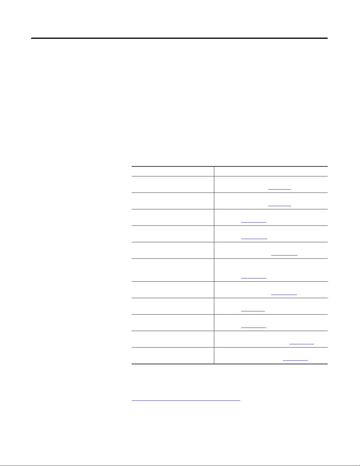
The table explains the new and updated information in this manual.
Section Changes
Chapter 3
Chapter 4
Appendix A
Appendix D
Appendix F
and Chapter 6 Caution for disabling all alarms because it affects the
Using electronic keying with examples of Exact Match,
Compatible, and Disabled Keying.
underrange/overrange detection feature.
Updated I/O specifications.
Updated power-sizing chart and link to an interactive
spreadsheet to calculate total power consumption for
modules in a chassis configuration.
Updated information on interface modules (IFMs)
and pre-wired cables that are available with
analog I/O modules.
Publication 1756-UM009C-EN-P - December 2010 3
Page 4

Summary of Changes
Notes:
4 Publication 1756-UM009C-EN-P - December 2010
Page 5

Table of Contents
Preface
What Are ControlLogix
Analog I/O Modules?
Analog I/O Operation in the
ControlLogix System
Introduction . . . . . . . . . . . . . . . . . . . . . . . . . . . . . . . . . . . . . . . . . . . . . . 13
Who Should Use This Manual. . . . . . . . . . . . . . . . . . . . . . . . . . . . . . . . 13
Additional Resources . . . . . . . . . . . . . . . . . . . . . . . . . . . . . . . . . . . . . . . 13
Chapter 1
Introduction . . . . . . . . . . . . . . . . . . . . . . . . . . . . . . . . . . . . . . . . . . . . . . 15
I/O Module in the ControlLogix System . . . . . . . . . . . . . . . . . . . . . . . 17
Module Identification and Status Information . . . . . . . . . . . . . . . . . . . 19
Preventing Electrostatic Discharge . . . . . . . . . . . . . . . . . . . . . . . . . . . . 20
Chapter 2
Introduction . . . . . . . . . . . . . . . . . . . . . . . . . . . . . . . . . . . . . . . . . . . . . . 21
Ownership . . . . . . . . . . . . . . . . . . . . . . . . . . . . . . . . . . . . . . . . . . . . . . . 21
Using RSNetWorx and RSLogix 5000 Software. . . . . . . . . . . . . . . . . . 22
Direct Connections . . . . . . . . . . . . . . . . . . . . . . . . . . . . . . . . . . . . . . . . 23
Input Module Operation . . . . . . . . . . . . . . . . . . . . . . . . . . . . . . . . . . . . 24
Input Modules in a Local Chassis . . . . . . . . . . . . . . . . . . . . . . . . . . . . . 24
Real Time Sample (RTS) . . . . . . . . . . . . . . . . . . . . . . . . . . . . . . . . . 24
Requested Packet Interval (RPI) . . . . . . . . . . . . . . . . . . . . . . . . . . . 25
Triggering Event Tasks . . . . . . . . . . . . . . . . . . . . . . . . . . . . . . . . . . 26
Input Modules in a Remote Chassis . . . . . . . . . . . . . . . . . . . . . . . . . . . 27
Remote Input Modules Connected Via
the ControlNet Network . . . . . . . . . . . . . . . . . . . . . . . . . . . . . . . . . 27
Remote Input Modules Connected Via
the EtherNet/IP Network . . . . . . . . . . . . . . . . . . . . . . . . . . . . . . . 28
Output Module Operation. . . . . . . . . . . . . . . . . . . . . . . . . . . . . . . . . . . 29
Output Modules in a Local Chassis. . . . . . . . . . . . . . . . . . . . . . . . . . . . 29
Output Modules in a Remote Chassis. . . . . . . . . . . . . . . . . . . . . . . . . . 30
Remote Output Modules Connected Via
the ControlNet Network . . . . . . . . . . . . . . . . . . . . . . . . . . . . . . . . . 30
Remote Output Modules Connected Via
the EtherNet/IP Network . . . . . . . . . . . . . . . . . . . . . . . . . . . . . . . 31
Listen-only Mode . . . . . . . . . . . . . . . . . . . . . . . . . . . . . . . . . . . . . . . . . . 32
Multiple Owners of Input Modules. . . . . . . . . . . . . . . . . . . . . . . . . . . . 33
Configuration Changes in an Input Module with Multiple Owners . . 34
Chapter 3
ControlLogix Analog
I/O Module Features
Publication 1756-UM009C-EN-P - December 2010 5
Introduction . . . . . . . . . . . . . . . . . . . . . . . . . . . . . . . . . . . . . . . . . . . . . . 35
Common Analog I/O Features. . . . . . . . . . . . . . . . . . . . . . . . . . . . . . . 35
Removal and Insertion Under Power (RIUP) . . . . . . . . . . . . . . . . 36
Module Fault Reporting . . . . . . . . . . . . . . . . . . . . . . . . . . . . . . . . . 36
Configurable Software . . . . . . . . . . . . . . . . . . . . . . . . . . . . . . . . . . . 36
Electronic Keying . . . . . . . . . . . . . . . . . . . . . . . . . . . . . . . . . . . . . . 37
Access to System Clock for Timestamp Functions . . . . . . . . . . . . 44
Rolling Timestamp. . . . . . . . . . . . . . . . . . . . . . . . . . . . . . . . . . . . . . 44
Producer/Consumer Model . . . . . . . . . . . . . . . . . . . . . . . . . . . . . . 44
Page 6

Table of Contents
Non-isolated Analog
Voltage/Current Input Modules
(1756-IF16, 1756-IF8)
Status Indicator Information. . . . . . . . . . . . . . . . . . . . . . . . . . . . . . 45
Full Class I Division 2 Compliance. . . . . . . . . . . . . . . . . . . . . . . . . 45
Agency Certification . . . . . . . . . . . . . . . . . . . . . . . . . . . . . . . . . . . . 45
Field Calibration. . . . . . . . . . . . . . . . . . . . . . . . . . . . . . . . . . . . . . . . 45
Sensor Offset . . . . . . . . . . . . . . . . . . . . . . . . . . . . . . . . . . . . . . . . . . 46
Latching of Alarms . . . . . . . . . . . . . . . . . . . . . . . . . . . . . . . . . . . . . 46
Data Format. . . . . . . . . . . . . . . . . . . . . . . . . . . . . . . . . . . . . . . . . . . 46
Module Inhibiting . . . . . . . . . . . . . . . . . . . . . . . . . . . . . . . . . . . . . . 47
Relationship Between Module Resolution, Scaling, Data Format . . . . 48
Module Resolution. . . . . . . . . . . . . . . . . . . . . . . . . . . . . . . . . . . . . . 48
Scaling. . . . . . . . . . . . . . . . . . . . . . . . . . . . . . . . . . . . . . . . . . . . . . . . 50
Data Format as Related to Resolution and Scaling . . . . . . . . . . . . 51
Chapter 4
Introduction . . . . . . . . . . . . . . . . . . . . . . . . . . . . . . . . . . . . . . . . . . . . . . 55
Choose a Wiring Method. . . . . . . . . . . . . . . . . . . . . . . . . . . . . . . . . . . . 56
Single-ended Wiring Method. . . . . . . . . . . . . . . . . . . . . . . . . . . . . . 56
Differential Wiring Method. . . . . . . . . . . . . . . . . . . . . . . . . . . . . . . 57
High-speed Mode Differential Wiring Method . . . . . . . . . . . . . . . 57
Choose a Data Format. . . . . . . . . . . . . . . . . . . . . . . . . . . . . . . . . . . . . . 58
Features Specific to Non-Isolated Analog Input Modules. . . . . . . . . . 59
Multiple Input Ranges . . . . . . . . . . . . . . . . . . . . . . . . . . . . . . . . . . . 59
Module Filter . . . . . . . . . . . . . . . . . . . . . . . . . . . . . . . . . . . . . . . . . . 60
Real Time Sampling . . . . . . . . . . . . . . . . . . . . . . . . . . . . . . . . . . . . . 61
Underrange/Overrange Detection . . . . . . . . . . . . . . . . . . . . . . . . . 61
Digital Filter . . . . . . . . . . . . . . . . . . . . . . . . . . . . . . . . . . . . . . . . . . . 62
Process Alarms. . . . . . . . . . . . . . . . . . . . . . . . . . . . . . . . . . . . . . . . . 63
Rate Alarm . . . . . . . . . . . . . . . . . . . . . . . . . . . . . . . . . . . . . . . . . . . . 64
Wire Off Detection . . . . . . . . . . . . . . . . . . . . . . . . . . . . . . . . . . . . . 64
Use Module Block and Input Circuit Diagrams . . . . . . . . . . . . . . . . . . 67
Field-side Circuit Diagrams. . . . . . . . . . . . . . . . . . . . . . . . . . . . . . . 68
Wire the 1756-IF16 Module . . . . . . . . . . . . . . . . . . . . . . . . . . . . . . . . . 70
Wire the 1756-IF8 Module . . . . . . . . . . . . . . . . . . . . . . . . . . . . . . . . . . 74
1756-IF16 Module Fault and Status Reporting . . . . . . . . . . . . . . . . . . 78
1756-IF16 Fault Reporting in Floating Point Mode. . . . . . . . . . . . . . . 79
1756-IF16 Module Fault Word Bits – Floating Point Mode . . . . . 80
1756-IF16 Channel Fault Word Bits – Floating Point Mode . . . . 80
1756-IF16 Channel Status Word Bits – Floating Point Mode. . . . 81
1756-IF16 Fault Reporting in Integer Mode. . . . . . . . . . . . . . . . . . . . . 82
1756-IF16 Module Fault Word Bits – Integer Mode. . . . . . . . . . . 83
1756-IF16 Channel Fault Word Bits – Integer Mode . . . . . . . . . . 83
1756-IF16 Channel Status Word Bits – Integer Mode . . . . . . . . . 84
1756-IF8 Module Fault and Status Reporting . . . . . . . . . . . . . . . . . . . 85
1756-IF8 Fault Reporting in Floating Point Mode. . . . . . . . . . . . . . . . 86
1756-IF8 Module Fault Word Bits – Floating Point Mode . . . . . . 87
1756-IF8 Channel Fault Word Bits – Floating Point Mode . . . . . 87
6 Publication 1756-UM009C-EN-P - December 2010
Page 7

Sourcing Current Loop Input
Module (1756-IF6CIS) and Isolated
Analog Voltage/Current Input
Module (1756-IF6I)
Table of Contents
1756-IF8 Channel Status Word Bits – Floating Point Mode. . . . . 88
1756-IF8 Fault Reporting in Integer Mode. . . . . . . . . . . . . . . . . . . . . . 89
1756-IF8 Module Fault Word Bits – Integer Mode . . . . . . . . . . . . 90
1756-IF8 Channel Fault Word Bits – Integer Mode . . . . . . . . . . . 90
1756-IF8 Channel Status Word Bits – Integer Mode . . . . . . . . . . 91
Chapter 5
Introduction . . . . . . . . . . . . . . . . . . . . . . . . . . . . . . . . . . . . . . . . . . . . . . 93
Use the Isolated Power Source on the 1756-IF6CIS . . . . . . . . . . . . . . 94
Power Calculations with the 1756-IF6CIS Module . . . . . . . . . . . . 94
Other Devices in the Wiring Loop . . . . . . . . . . . . . . . . . . . . . . . . . 94
Choose a Data Format . . . . . . . . . . . . . . . . . . . . . . . . . . . . . . . . . . . . . . 95
Features Specific to the 1756-IF6I and 1756-IF6CIS Modules . . . . . . 96
Multiple Input Ranges . . . . . . . . . . . . . . . . . . . . . . . . . . . . . . . . . . . 96
Notch Filter . . . . . . . . . . . . . . . . . . . . . . . . . . . . . . . . . . . . . . . . . . . 97
Real Time Sampling . . . . . . . . . . . . . . . . . . . . . . . . . . . . . . . . . . . . . 98
Underrange/Overrange Detection . . . . . . . . . . . . . . . . . . . . . . . . . 98
Digital Filter . . . . . . . . . . . . . . . . . . . . . . . . . . . . . . . . . . . . . . . . . . . 99
Process Alarms. . . . . . . . . . . . . . . . . . . . . . . . . . . . . . . . . . . . . . . . 100
Rate Alarm . . . . . . . . . . . . . . . . . . . . . . . . . . . . . . . . . . . . . . . . . . . 101
Wire Off Detection . . . . . . . . . . . . . . . . . . . . . . . . . . . . . . . . . . . . 102
Use Module Block and Input Circuit Diagrams . . . . . . . . . . . . . . . . . 104
Field-side Circuit Diagrams . . . . . . . . . . . . . . . . . . . . . . . . . . . . . . 105
Wire the 1756-IF6CIS Module . . . . . . . . . . . . . . . . . . . . . . . . . . . . . . 106
Wire the 1756-IF6I Module . . . . . . . . . . . . . . . . . . . . . . . . . . . . . . . . 109
1756-IF6CIS or 1756-IF6I Module Fault and Status Reporting . . . . 111
Fault Reporting in Floating Point Mode . . . . . . . . . . . . . . . . . . . . . . . 112
Module Fault Word Bits – Floating Point Mode . . . . . . . . . . . . . 113
Channel Fault Word Bits – Floating Point Mode . . . . . . . . . . . . 113
Channel Status Word Bits – Floating Point Mode . . . . . . . . . . . . 114
Fault Reporting in Integer Mode. . . . . . . . . . . . . . . . . . . . . . . . . . . . . 115
Module Fault Word Bits – Integer Mode . . . . . . . . . . . . . . . . . . . 116
Channel Fault Word Bits – Integer Mode . . . . . . . . . . . . . . . . . . 116
Channel Status Word Bits – Integer Mode. . . . . . . . . . . . . . . . . . 117
Publication 1756-UM009C-EN-P - December 2010 7
Page 8

Table of Contents
Temperature-measuring Analog
Modules (1756-IR6I, 1756-IT6I,
and 1756-IT6I2)
Chapter 6
Introduction . . . . . . . . . . . . . . . . . . . . . . . . . . . . . . . . . . . . . . . . . . . . . 119
Choose a Data Format. . . . . . . . . . . . . . . . . . . . . . . . . . . . . . . . . . . . . 120
Temperature-measuring Module Features . . . . . . . . . . . . . . . . . . . . . 121
Multiple Input Ranges . . . . . . . . . . . . . . . . . . . . . . . . . . . . . . . . . . 121
Notch Filter . . . . . . . . . . . . . . . . . . . . . . . . . . . . . . . . . . . . . . . . . . 122
Real Time Sampling . . . . . . . . . . . . . . . . . . . . . . . . . . . . . . . . . . . . 123
Underrange/Overrange Detection . . . . . . . . . . . . . . . . . . . . . . . . 123
Digital Filter . . . . . . . . . . . . . . . . . . . . . . . . . . . . . . . . . . . . . . . . . . 124
Process Alarms. . . . . . . . . . . . . . . . . . . . . . . . . . . . . . . . . . . . . . . . 125
Rate Alarm . . . . . . . . . . . . . . . . . . . . . . . . . . . . . . . . . . . . . . . . . . . 126
10 Ohm Offset. . . . . . . . . . . . . . . . . . . . . . . . . . . . . . . . . . . . . . . . 126
Wire Off Detection . . . . . . . . . . . . . . . . . . . . . . . . . . . . . . . . . . . . 127
Sensor Type . . . . . . . . . . . . . . . . . . . . . . . . . . . . . . . . . . . . . . . . . . 128
Temperature Units. . . . . . . . . . . . . . . . . . . . . . . . . . . . . . . . . . . . . 130
Input Signal to User Count Conversion . . . . . . . . . . . . . . . . . . . . 130
Wire Length Calculations . . . . . . . . . . . . . . . . . . . . . . . . . . . . . . . 131
Differences Between the 1756-IT6I and 1756-IT6I2 Modules . . . . . 131
Cold Junction Compensation . . . . . . . . . . . . . . . . . . . . . . . . . . . . 132
Improved Module Accuracy . . . . . . . . . . . . . . . . . . . . . . . . . . . . . 135
Use Module Block and Input Circuit Diagrams . . . . . . . . . . . . . . . . . 136
Field-side Circuit Diagrams. . . . . . . . . . . . . . . . . . . . . . . . . . . . . . 137
Wire the Modules . . . . . . . . . . . . . . . . . . . . . . . . . . . . . . . . . . . . . . . . . 138
Fault and Status Reporting. . . . . . . . . . . . . . . . . . . . . . . . . . . . . . . . . . 141
Fault Reporting in Floating Point Mode . . . . . . . . . . . . . . . . . . . . . . . 142
Module Fault Word Bits – Floating Point Mode . . . . . . . . . . . . . 143
Channel Fault Word Bits – Floating Point Mode . . . . . . . . . . . . 143
Channel Status Word Bits – Floating Point Mode . . . . . . . . . . . . 144
Fault Reporting in Integer Mode. . . . . . . . . . . . . . . . . . . . . . . . . . . . . 145
Module Fault Word Bits – Integer Mode . . . . . . . . . . . . . . . . . . . 146
Channel Fault Word Bits – Integer Mode . . . . . . . . . . . . . . . . . . 146
Channel Status Word Bits – Integer Mode. . . . . . . . . . . . . . . . . . 147
Chapter 7
Non-isolated Analog Output
Modules (1756-OF4 and 1756-OF8)
8 Publication 1756-UM009C-EN-P - December 2010
Introduction . . . . . . . . . . . . . . . . . . . . . . . . . . . . . . . . . . . . . . . . . . . . . 149
Choose a Data Format. . . . . . . . . . . . . . . . . . . . . . . . . . . . . . . . . . . . . 150
Non-isolated Output Module Features . . . . . . . . . . . . . . . . . . . . . . . . 150
Ramping/Rate Limiting. . . . . . . . . . . . . . . . . . . . . . . . . . . . . . . . . 151
Hold for Initialization . . . . . . . . . . . . . . . . . . . . . . . . . . . . . . . . . . 151
Open Wire Detection . . . . . . . . . . . . . . . . . . . . . . . . . . . . . . . . . . 152
Clamping/Limiting . . . . . . . . . . . . . . . . . . . . . . . . . . . . . . . . . . . . 152
Clamp/Limit Alarms . . . . . . . . . . . . . . . . . . . . . . . . . . . . . . . . . . . 153
Data Echo . . . . . . . . . . . . . . . . . . . . . . . . . . . . . . . . . . . . . . . . . . . 153
User Count Conversion to Output Signal . . . . . . . . . . . . . . . . . . 153
Use Module Block and Output Circuit Diagrams . . . . . . . . . . . . . . . 154
Page 9

Isolated Analog Output Modules
(1756-OF6CI and 1756-OF6VI)
Table of Contents
Field-side Circuit Diagrams . . . . . . . . . . . . . . . . . . . . . . . . . . . . . . 156
Wire the 1756-OF4 Module. . . . . . . . . . . . . . . . . . . . . . . . . . . . . . . . . 157
Wire the 1756-OF8 Module. . . . . . . . . . . . . . . . . . . . . . . . . . . . . . . . . 158
1756-OF4 and 1756-OF8 Module Fault and Status Reporting . . . . . 159
1756-OF4 and 1756-OF8 Fault Reporting in Floating Point Mode . 160
Module Fault Word Bits – Floating Point Mode . . . . . . . . . . . . . 161
Channel Fault Word Bits – Floating Point Mode . . . . . . . . . . . . 161
Channel Status Words Bits – Floating Point Mode . . . . . . . . . . . 162
1756-OF4 and 1756-OF8 Fault Reporting in Integer Mode . . . . . . . 163
Module Fault Word Bits – Integer Mode . . . . . . . . . . . . . . . . . . . 164
Channel Fault Word Bits – Integer Mode . . . . . . . . . . . . . . . . . . 164
Channel Status Word Bits – Integer Mode. . . . . . . . . . . . . . . . . . 165
Chapter 8
Introduction . . . . . . . . . . . . . . . . . . . . . . . . . . . . . . . . . . . . . . . . . . . . . 167
Choose a Data Format . . . . . . . . . . . . . . . . . . . . . . . . . . . . . . . . . . . . . 168
Isolated Output Module Features . . . . . . . . . . . . . . . . . . . . . . . . . . . . 168
Ramping/Rate Limiting. . . . . . . . . . . . . . . . . . . . . . . . . . . . . . . . . 169
Hold for Initialization . . . . . . . . . . . . . . . . . . . . . . . . . . . . . . . . . . 169
Clamping/Limiting . . . . . . . . . . . . . . . . . . . . . . . . . . . . . . . . . . . . 170
Clamp/Limit Alarms . . . . . . . . . . . . . . . . . . . . . . . . . . . . . . . . . . . 170
Data Echo . . . . . . . . . . . . . . . . . . . . . . . . . . . . . . . . . . . . . . . . . . . 171
User Count Conversion to Output Signal . . . . . . . . . . . . . . . . . . 171
Use Module Block and Output Circuit Diagrams . . . . . . . . . . . . . . . 172
Field-side Circuit Diagrams . . . . . . . . . . . . . . . . . . . . . . . . . . . . . . 174
Drive Different Loads with the 1756-OF6CI. . . . . . . . . . . . . . . . . . . 174
Wire the 1756-OF6CI Module . . . . . . . . . . . . . . . . . . . . . . . . . . . . . . 177
Wire the 1756-OF6VI Module . . . . . . . . . . . . . . . . . . . . . . . . . . . . . . 178
1756-OF6CI and 1756-OF6VI Module Fault, Status Reporting . . . . 179
Fault Reporting in Floating Point Mode . . . . . . . . . . . . . . . . . . . . . . . 180
Module Fault Word Bits – Floating Point Mode . . . . . . . . . . . . . 181
Channel Fault Word Bits – Floating Point Mode . . . . . . . . . . . . 181
Channel Status Word Bits – Floating Point Mode . . . . . . . . . . . . 182
Fault Reporting in Integer Mode. . . . . . . . . . . . . . . . . . . . . . . . . . . . . 183
Module Fault Word Bits – Integer Mode . . . . . . . . . . . . . . . . . . . 184
Channel Fault Word Bits – Integer Mode . . . . . . . . . . . . . . . . . . 184
Channel Status Word Bits in Integer Mode . . . . . . . . . . . . . . . . . 185
Publication 1756-UM009C-EN-P - December 2010 9
Page 10

Table of Contents
Install ControlLogix I/O Modules
Configure ControlLogix
Analog I/O Modules
Chapter 9
Introduction . . . . . . . . . . . . . . . . . . . . . . . . . . . . . . . . . . . . . . . . . . . . . 187
Install the I/O Module . . . . . . . . . . . . . . . . . . . . . . . . . . . . . . . . . . . . 187
Key the Removable Terminal Block . . . . . . . . . . . . . . . . . . . . . . . . . . 188
Connect Wiring . . . . . . . . . . . . . . . . . . . . . . . . . . . . . . . . . . . . . . . . . . 189
Connect the Grounded End of the Cable . . . . . . . . . . . . . . . . . . 190
Connect the Ungrounded End of the Cable . . . . . . . . . . . . . . . . 192
Three Types of RTBs (each RTB comes with housing) . . . . . . . 192
Recommendations for Wiring Your RTB. . . . . . . . . . . . . . . . . . . 194
Assemble the RTB and the Housing. . . . . . . . . . . . . . . . . . . . . . . . . . 194
Install the Removable Terminal Block . . . . . . . . . . . . . . . . . . . . . . . . 195
Remove the Removable Terminal Block . . . . . . . . . . . . . . . . . . . . . . 196
Remove the Module from the Chassis . . . . . . . . . . . . . . . . . . . . . . . . 197
Chapter 10
Introduction . . . . . . . . . . . . . . . . . . . . . . . . . . . . . . . . . . . . . . . . . . . . . 199
Configuration Process Overview . . . . . . . . . . . . . . . . . . . . . . . . . 200
Create a New Module . . . . . . . . . . . . . . . . . . . . . . . . . . . . . . . . . . . . . 202
Communication Format . . . . . . . . . . . . . . . . . . . . . . . . . . . . . . . . 205
Modify Default Configuration for Input Modules . . . . . . . . . . . . . . . 207
Connection Tab . . . . . . . . . . . . . . . . . . . . . . . . . . . . . . . . . . . . . . . 209
Configuration Tab . . . . . . . . . . . . . . . . . . . . . . . . . . . . . . . . . . . . . 210
Alarm Configuration Tab . . . . . . . . . . . . . . . . . . . . . . . . . . . . . . . 212
Calibration Tab . . . . . . . . . . . . . . . . . . . . . . . . . . . . . . . . . . . . . . . 214
Configure the RTD Module . . . . . . . . . . . . . . . . . . . . . . . . . . . . . . . . 215
Configure the Thermocouple Modules . . . . . . . . . . . . . . . . . . . . . . . . 216
Modify Default Configuration for Output Modules . . . . . . . . . . . . . 218
Connection Tab . . . . . . . . . . . . . . . . . . . . . . . . . . . . . . . . . . . . . . . 219
Configuration Tab . . . . . . . . . . . . . . . . . . . . . . . . . . . . . . . . . . . . . 220
Output State Tab . . . . . . . . . . . . . . . . . . . . . . . . . . . . . . . . . . . . . 221
Limits Tab . . . . . . . . . . . . . . . . . . . . . . . . . . . . . . . . . . . . . . . . . . . 223
Calibration Tab . . . . . . . . . . . . . . . . . . . . . . . . . . . . . . . . . . . . . . . 225
Download Configuration Data to the Module . . . . . . . . . . . . . . . . . . 225
Edit Configuration . . . . . . . . . . . . . . . . . . . . . . . . . . . . . . . . . . . . . . . . 226
Reconfigure Module Parameters in Run Mode . . . . . . . . . . . . . . . . . 227
Reconfigure Parameters in Program Mode. . . . . . . . . . . . . . . . . . . . . 229
Configure I/O Modules in a Remote Chassis . . . . . . . . . . . . . . . . . . 230
View Module Tags . . . . . . . . . . . . . . . . . . . . . . . . . . . . . . . . . . . . . . . . 232
10 Publication 1756-UM009C-EN-P - December 2010
Page 11

Calibrate the ControlLogix
Analog I/O Modules
Troubleshoot Your Module
Table of Contents
Chapter 11
Introduction . . . . . . . . . . . . . . . . . . . . . . . . . . . . . . . . . . . . . . . . . . . . . 233
Difference of Calibrating an Input Module and Output Module . . . 234
Calibrating in Either Program or Run Mode . . . . . . . . . . . . . . . . 235
Calibrate Your Input Modules. . . . . . . . . . . . . . . . . . . . . . . . . . . . . . . 235
Calibrating the 1756-IF16 or 1756-IF8 Modules . . . . . . . . . . . . . 235
Calibrating the 1756-IF6CIS or 1756-IF6I Modules . . . . . . . . . . 241
Calibrating the 1756-IR6I . . . . . . . . . . . . . . . . . . . . . . . . . . . . . . . 248
Calibrating the 1756-IT6I or 1756-IT6I2 . . . . . . . . . . . . . . . . . . . 253
Calibrate Your Output Modules . . . . . . . . . . . . . . . . . . . . . . . . . . . . . 259
Current Meter Calibrations . . . . . . . . . . . . . . . . . . . . . . . . . . . . . . 259
Voltage Meter Calibrations . . . . . . . . . . . . . . . . . . . . . . . . . . . . . . 266
Chapter 12
Introduction . . . . . . . . . . . . . . . . . . . . . . . . . . . . . . . . . . . . . . . . . . . . . 273
Status Indicators for Input Modules . . . . . . . . . . . . . . . . . . . . . . . 273
Status Indicators for Output Modules . . . . . . . . . . . . . . . . . . . . . 274
Use RSLogix 5000 Software for Troubleshooting . . . . . . . . . . . . . . . 275
Fault Type Determination . . . . . . . . . . . . . . . . . . . . . . . . . . . . . . . 276
Analog I/O Module Specifications
Analog I/O Tag Definitions
Appendix A
1756-IF6CIS. . . . . . . . . . . . . . . . . . . . . . . . . . . . . . . . . . . . . . . . . . 279
1756-IF6I . . . . . . . . . . . . . . . . . . . . . . . . . . . . . . . . . . . . . . . . . . . . 284
1756-IF8 . . . . . . . . . . . . . . . . . . . . . . . . . . . . . . . . . . . . . . . . . . . . . 289
1756-IF16 . . . . . . . . . . . . . . . . . . . . . . . . . . . . . . . . . . . . . . . . . . . . 294
1756-IR6I . . . . . . . . . . . . . . . . . . . . . . . . . . . . . . . . . . . . . . . . . . . . 299
1756-IT6I . . . . . . . . . . . . . . . . . . . . . . . . . . . . . . . . . . . . . . . . . . . . 304
1756-IT6I2 . . . . . . . . . . . . . . . . . . . . . . . . . . . . . . . . . . . . . . . . . . . 308
1756-OF4 . . . . . . . . . . . . . . . . . . . . . . . . . . . . . . . . . . . . . . . . . . . . 312
1756-OF6CI. . . . . . . . . . . . . . . . . . . . . . . . . . . . . . . . . . . . . . . . . . 316
1756-OF6VI. . . . . . . . . . . . . . . . . . . . . . . . . . . . . . . . . . . . . . . . . . 320
1756-OF8 . . . . . . . . . . . . . . . . . . . . . . . . . . . . . . . . . . . . . . . . . . . . 323
Appendix B
Integer Mode Tags . . . . . . . . . . . . . . . . . . . . . . . . . . . . . . . . . . . . . . . . 327
Integer Input Tags . . . . . . . . . . . . . . . . . . . . . . . . . . . . . . . . . . . . . 327
Integer Output Tags . . . . . . . . . . . . . . . . . . . . . . . . . . . . . . . . . . . 328
Integer Configuration Tags . . . . . . . . . . . . . . . . . . . . . . . . . . . . . 329
Floating Point Mode Tags . . . . . . . . . . . . . . . . . . . . . . . . . . . . . . . . . . 331
Floating Point Input Tags . . . . . . . . . . . . . . . . . . . . . . . . . . . . . . . 331
Floating Point Output Tags . . . . . . . . . . . . . . . . . . . . . . . . . . . . . 333
Floating Point Configuration Tags . . . . . . . . . . . . . . . . . . . . . . . . 334
Publication 1756-UM009C-EN-P - December 2010 11
Page 12

Table of Contents
Use Ladder Logic To Perform
Run Time Services and
Reconfiguration
Choose Correct Power Supply
Additional Specification
Information
Appendix C
Using Message Instructions. . . . . . . . . . . . . . . . . . . . . . . . . . . . . . 339
Processing Real-time Control and Module Services. . . . . . . . . . . 339
One Service Performed Per Instruction . . . . . . . . . . . . . . . . . . . . 340
Create a New Tag. . . . . . . . . . . . . . . . . . . . . . . . . . . . . . . . . . . . . . . . . 340
Enter Message Configuration . . . . . . . . . . . . . . . . . . . . . . . . . . . . 344
Configuration Tab . . . . . . . . . . . . . . . . . . . . . . . . . . . . . . . . . . . . . 345
Communication Tab . . . . . . . . . . . . . . . . . . . . . . . . . . . . . . . . . . . 347
Unlatch Alarms in the 1756-IF6I Module . . . . . . . . . . . . . . . . . . 348
Unlatch Alarms in the 1756-OF6VI Module . . . . . . . . . . . . . . . . 351
Reconfiguring a 1756-IR6I Module . . . . . . . . . . . . . . . . . . . . . . . 353
Considerations With This Ladder Logic Example . . . . . . . . . . . . 355
Perform Module Reset Service . . . . . . . . . . . . . . . . . . . . . . . . . . . 357
Appendix D
Power-sizing Chart . . . . . . . . . . . . . . . . . . . . . . . . . . . . . . . . . . . . . . . . 359
Appendix E
Analog to Digital (A/D) Converter Accuracy . . . . . . . . . . . . . . . . . . 361
Calibrated Accuracy . . . . . . . . . . . . . . . . . . . . . . . . . . . . . . . . . . . . . . . 362
Error Calculated Over Hardware Range . . . . . . . . . . . . . . . . . . . . . . . 363
How Operating Temperature Changes Affect Module Accuracy . . . 363
Gain Drift With Temperature . . . . . . . . . . . . . . . . . . . . . . . . . . . . 363
Module Error Over Full Temperature Range . . . . . . . . . . . . . . . 364
RTD and Thermocouple Error Calculations . . . . . . . . . . . . . . . . . . . 365
RTD Error . . . . . . . . . . . . . . . . . . . . . . . . . . . . . . . . . . . . . . . . . . . 365
Thermocouple Error . . . . . . . . . . . . . . . . . . . . . . . . . . . . . . . . . . . 366
Module Error at 25 °C (77 °F) (-12…30 mV Range) . . . . . . . . . 367
Module Error at 25 °C (77 °F) (-12…78 mV Range) . . . . . . . . . 370
Thermocouple Resolution . . . . . . . . . . . . . . . . . . . . . . . . . . . . . . . . . . 373
Module Resolution (-12…30 mV Range). . . . . . . . . . . . . . . . . . . 374
Module Resolution (-12…78 mV Range). . . . . . . . . . . . . . . . . . . 377
How to Deal with Incorrect Thermocouple Temp Readings . . . 381
Appendix F
1492 AIFMs for Analog
Introduction . . . . . . . . . . . . . . . . . . . . . . . . . . . . . . . . . . . . . . . . . . . . . 383
I/O Modules
Glossary
Index
12 Publication 1756-UM009C-EN-P - December 2010
Page 13
Preface
Introduction
Who Should Use This
Manual
Additional Resources
This manual describes how to install, configure, and troubleshoot your
ControlLogix analog I/O module.
You must be able to program and operate a Rockwell Automation
ControlLogix controller to efficiently use your analog I/O modules. If you
need additional information, refer to the related documentation listed below.
The following table lists related ControlLogix products and documentation.
Related Documentation
Cat. No. Resource
1756-A4, 1756-A7, 1756-A10,
1756-A13, 1756-A17
1756-PA72, 1756-PB72, 1756-PA75,
1756-PB75, 1756-PH75, 1756-PC75
1756 digital I/O modules ControlLogix Digital I/O Modules User Manual,
1756-CNB, 1756-CNBR ControlNet Modules in Logix5000 Control Systems,
ControlLogix Chassis, Series B Installation
Instructions, publication
ControlLogix Power Supplies Installation
Instructions, publication
publication
publication
1756-UM058
CNET-UM001
1756-IN080
1756-IN613
1756-DNB DeviceNet Modules in Logix5000 Control Systems
User Manual, publication
1756-DHRIO ControlLogix Data Highway Plus-Remote I/O
Communication Interface Module User Manual,
publication
1756-ENBT, 1769-ENET EtherNet/IP Modules in Logix5000 Control Systems
User Manual, publication
1756-Lx ControlLogix Selection Guide,
publication
1756-Lx ControlLogix System User Manual,
publication
1756-Lx, 1769-Lx, 1789-Lx,
PowerFlex 700S
1756-Lx, 1769-Lx, 1789-Lx, 1794-Lx,
PowerFlex 700S
Logix5000 Controllers Common Procedures
Programming Manual, publication
Logix5000 Controllers General Instructions
Reference Manual, publication
1756-UM514
1756-SG001
1756-UM001
DNET-UM004
ENET-UM001
1756-PM001
1756-RM003
If you need more information on these products, contact your local Rockwell
Automation distributor or sales office. The documentation listed in the Related
Documentation table is available at
http://www..rockwellautomation.com/literature
.
Publication 1756-UM009C-EN-P - December 2010 13
Page 14

Preface
Notes:
14 Publication 1756-UM009C-EN-P - December 2010
Page 15

Chapter
1
What Are ControlLogix Analog I/O Modules?
Introduction
This chapter provides an overview of the ControlLogix analog I/O modules
to explain to you how they operate.
Topic Page
I/O Module in the ControlLogix System 17
Parts Illustration of the ControlLogix Analog I/O Module 18
Module Identification and Status Information 19
Preventing Electrostatic Discharge 20
ControlLogix analog I/O modules are interface modules that convert analog
signals to digital values for inputs and convert digital values to analog signals
for outputs. Controllers can then use these signals for control purposes.
By using the producer/consumer network model, ControlLogix analog I/O
modules produce information when needed while providing additional system
functions.
The table lists several features available on ControlLogix analog I/O modules.
ControlLogix Analog I/O Module Features
Feature Description
Removal and insertion
under power (RIUP)
Producer/consumer
communication
Rolling timestamp of data A 15-bit module-specific rolling timestamp with millisecond
Multiple data formats Analog I/O modules offer the option of IEEE 32-bit floating
Module resolution Analog input modules use 16-bit resolution, and analog
On-board features Scaling to engineering units, alarming, and under/overrange
Publication 1756-UM009C-EN-P - December 2010 15
You can remove and insert modules and removable terminal
blocks (RTB) while power is applied.
This communication is an intelligent data exchange
between modules and other system devices in which each
module produces data without first being polled.
resolution that indicates when data was sampled and/or
applied. This timestamp may be used to calculate the
interval between channel or field-side updates.
point or 16-bit integer data formats.
output modules offer 13…16-bit output resolution
(depending on the module type), to detect data changes.
detection, are some examples of the I/O module features.
Page 16

Chapter 1 What Are ControlLogix Analog I/O Modules?
ControlLogix Analog I/O Module Features
Feature Description
Calibration ControlLogix analog I/O module ships from the factory with
Coordinated system time
(CST) time stamp of data
Agency Certification
factory calibration. You can recalibrate the module
calibration on a channel-by-channel or module-wide basis to
increase accuracy in customer-specific applications,
if necessary.
A 64-bit system clock places a time stamp on the transfer of
data between the module and its owner-controller within
the local chassis.
Full agency certification for in any application that requires
approval.
Agency certification varies depending on the catalog
number. To see a list of the certifications associated with
each catalog number, see
Appendix A
.
16 Publication 1756-UM009C-EN-P - December 2010
Page 17
What Are ControlLogix Analog I/O Modules? Chapter 1
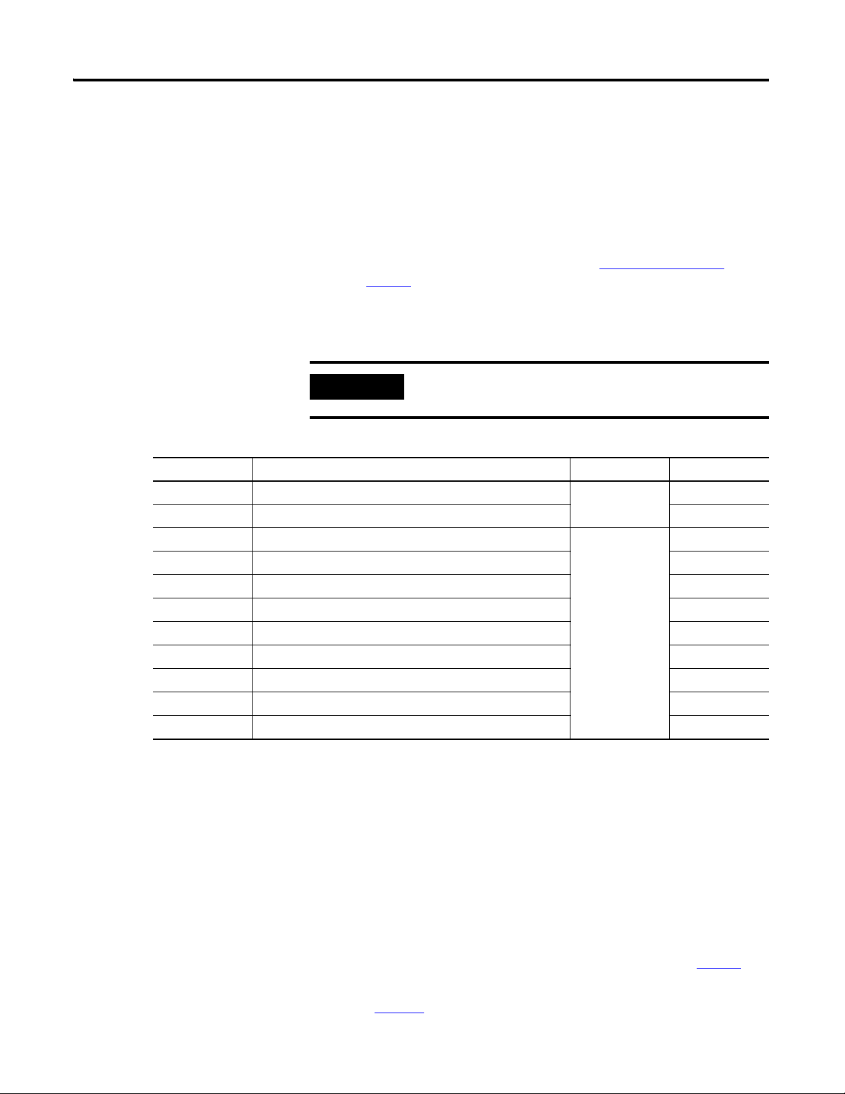
IMPORTANT
I/O Module in the ControlLogix System
Types of ControlLogix Analog I/O Modules
Cat. No. Description RTB Used Page
1756-IF16 16-point non-isolated analog current/voltage input module
1756-IF8 8-point non-isolated analog current/voltage input module 289
ControlLogix modules mount in a ControlLogix chassis and use a removable
terminal block (RTB) or a Bulletin 1492 interface module
(1)
cable to connect
to all field-side wiring.
Before you install and use your module, you should do the following:
• Install and ground a 1756 chassis and power supply
(2)
. To install these
products, refer to the publications listed in Additional Resources
on page 13.
• Order and receive an RTB or IFM and its components for your
application.
RTBs and IFMs are not included with your
module purchase.
36-pin
294
1756-IF6CIS 6-point sourcing current loop input module
279
1756-IF6I 6-point isolated analog current/voltage input module 284
1756-IR6I 6-point isolated RTD input module 299
1756-IT6I 6-point isolated Thermocouple/mV input module 304
1756-IT6I2 6-point isolated Enhanced Thermocouple/mV input module 308
20-pin
1756-OF4 4-point non-isolated analog current/voltage output module 312
1756-OF8 8-point non-isolated analog current/voltage output module 323
1756-OF6CI 6-point isolated analog current output module 316
1756-OF6VI 6-point isolated analog voltage output module 320
(1)
The ControlLogix system has been agency certified using only the ControlLogix RTBs (1756-TBCH, 1756-TBNH,
1756-TBSH and 1756-TBS6H). Any application that requires agency certification of the ControlLogix system
using other wiring termination methods may require application specific approval by the certifying agency. To
see what analog interface modules are used with each ControlLogix analog I/O module, see Appendix F
(2)
In addition to standard ControlLogix power supplies, ControlLogix Redundant Power Supplies are also available
for your application. For more information on these supplies, see the ControlLogix Selection Guide,
publication 1756-SG001
, or contact your local Rockwell Automation distributor or sales representative.
.
Publication 1756-UM009C-EN-P - December 2010 17
Page 18
Chapter 1 What Are ControlLogix Analog I/O Modules?
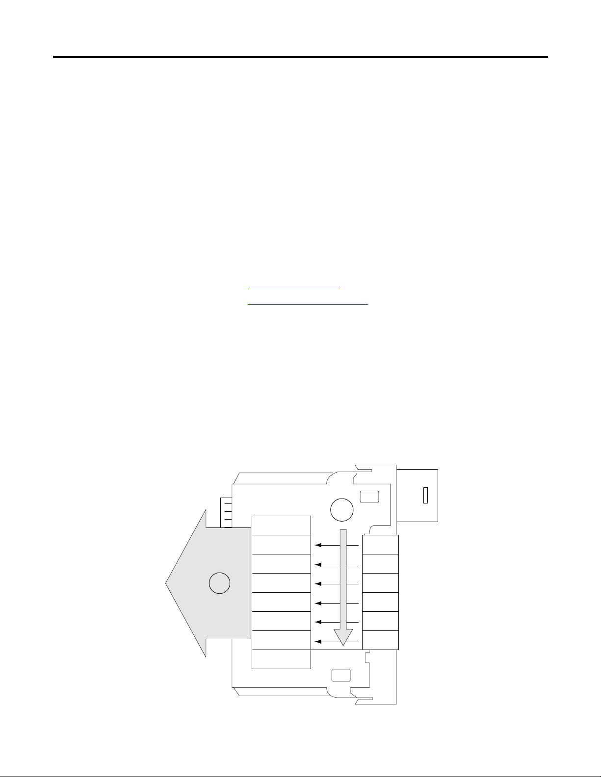
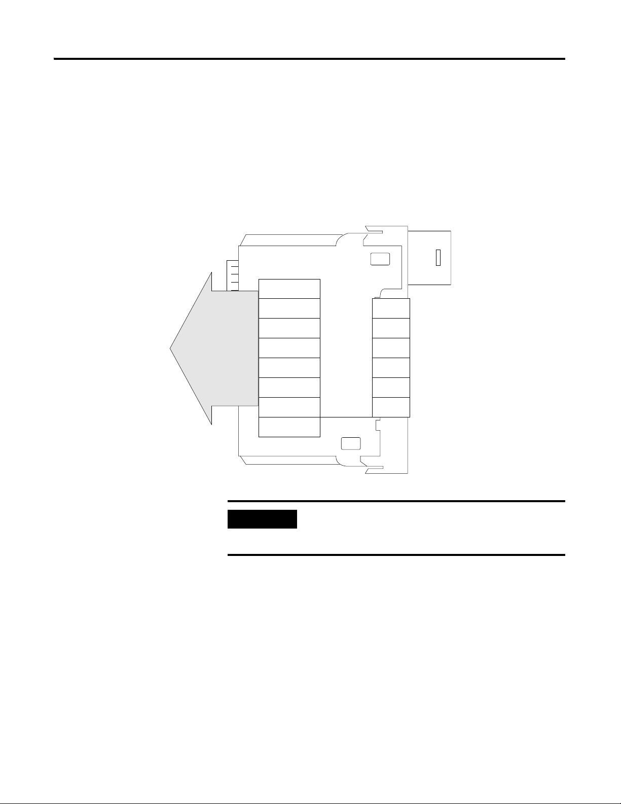
Removable Terminal Block
1
2
3
4
5
6
40200-M
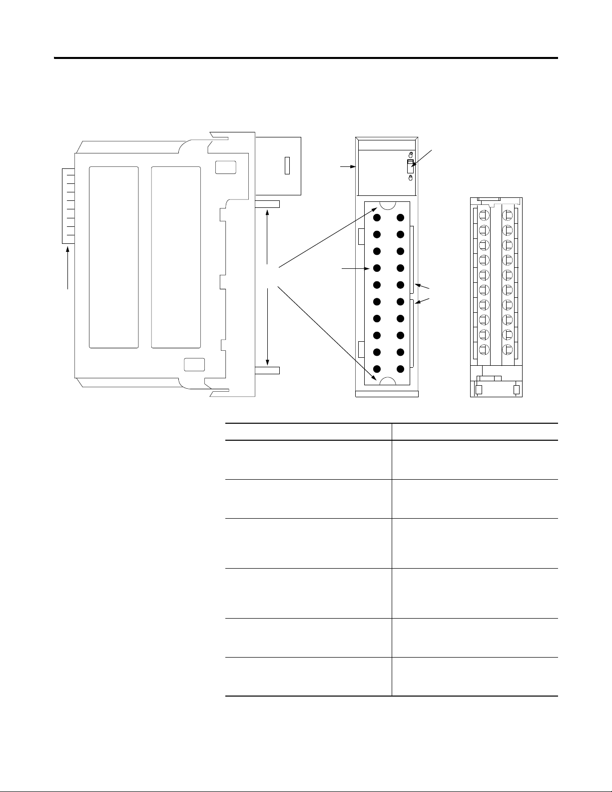
Parts Illustration of the ControlLogix Analog I/O Module
Item Description
1 Backplane connector - Interface for the
ControlLogix system that connects the
module to the backplane.
2 Top and bottom guides - Guides provide
assistance in seating the RTB or IFM cable
onto the module.
3 Status indicators - Indicators display the
status of communication, module health,
and input/output devices. Indicators help in
troubleshooting anomalies.
4 Connectors pins - Input/output, power,
and grounding connections are made to the
module through these pins with the use of
an RTB or IFM.
5 Locking tab - The locking tab anchors the
RTB or IFM cable on the module,
maintaining wiring connections.
6 Slots for keying - Mechanically keys the
RTB to prevent inadvertently making the
wrong wire connections to your module.
18 Publication 1756-UM009C-EN-P - December 2010
Page 19

What Are ControlLogix Analog I/O Modules? Chapter 1
IMPORTANT
Module Identification and Status Information
Each ControlLogix I/O module maintains specific identification information
that separates it from all other modules. This information assists you in
tracking all the components of your system.
For example, you can track module identification information to be aware of
exactly what modules are located in any ControlLogix rack at any time. While
retrieving module identity, you can also retrieve the module’s status.
Module Identification and Status Information
Item Description
Product Type Module’s product type, such as Analog I/O
or Digital I/O module
Catalog Code Module’s catalog number
Major Revision Module’s major revision number
Minor Revision Module’s minor revision number
Status Module’s status that shows the following information:
• Controller ownership (if any)
• Whether module has been configured
• Device Specific Status, such as:
• Self-Test
• Flash update in progress
• Communications fault
• Not owned (outputs in program mode)
• Internal fault (need flash update)
• Run mode
• Program mode (output mods only)
• Minor recoverable fault
• Minor unrecoverable fault
• Major recoverable fault
• Major unrecoverable fault
Vendor ID Module manufacturer vendor, for example Allen-Bradley
Serial Number Module serial number
Length of ASCII Text String Number of characters in module’s text string
ASCII Text String Number of characters in module’s text string
You must perform a WHO service to retrieve this information.
Publication 1756-UM009C-EN-P - December 2010 19
Page 20

Chapter 1 What Are ControlLogix Analog I/O Modules?
ATTENTION
Preventing Electrostatic Discharge
This module is sensitive to electrostatic discharge.
This equipment is sensitive to electrostatic discharge, which
can cause internal damage and affect normal operation. Follow
these guidelines when you handle this equipment:
• Touch a grounded object to discharge potential static.
• Wear an approved grounding wriststrap.
• Do not touch connectors or pins on component
boards.
• Do not touch circuit components inside the equipment.
• If available, use a static-safe workstation.
• When not in use, store the equipment in appropriate
static-safe packaging.
20 Publication 1756-UM009C-EN-P - December 2010
Page 21

Analog I/O Operation in the ControlLogix System
Chapter
2
Introduction
I/O modules are interfaces between the controller and the field devices that
comprise the ControlLogix system. Analog signals, which are continuous, are
converted by the module and used by the controller to mandate field-device
results.
This chapter describes how analog I/O modules operate within the
ControlLogix system.
Topic Page
Ownership 21
Using RSNetWorx and RSLogix 5000 Software 22
Direct Connections 23
Input Module Operation 24
Input Modules in a Local Chassis 24
Real Time Sample (RTS) 24
Requested Packet Interval (RPI) 25
Input Modules in a Remote Chassis 27
Output Module Operation 29
Output Modules in a Local Chassis 29
Output Modules in a Remote Chassis 30
Listen-only Mode 32
Multiple Owners of Input Modules 33
Configuration Changes in an Input Module with Multiple Owners 34
Ownership
Publication 1756-UM009C-EN-P - December 2010 21
Every I/O module in the ControlLogix system must be owned by a
ControlLogix controller. This owner-controller:
• stores configuration data for every module that it owns.
• can be local or remote in regard to the I/O module’s position.
• sends the I/O module configuration data to define the module’s
behavior and begin operation within the control system.
Each ControlLogix I/O module must continuously maintain communication
with its owner to operate normally.
Page 22

Chapter 2 Analog I/O Operation in the ControlLogix System
Typically, each module in the system will have one owner only. Input modules
can have more than one owner. Output modules, however, are limited to a
single owner.
For more information on the increased flexibility provided by multiple owners
and the ramifications of using multiple owners, see
Input Module with Multiple Owners
on
page 34
Configuration Changes in an
.
Using RSNetWorx and RSLogix 5000 Software
The I/O configuration portion of the RSLogix5000 programming software
generates the configuration data for each I/O module in the control system,
whether the module is in a local or remote chassis. A remote chassis, also
known as networked, contains the I/O module but not the module’s
owner-controller. A remote chassis can be connected to the controller via a
scheduled connection on the ControlNet network or an
EtherNet/IP network.
RSLogix 5000 configuration data is transferred to the controller during the
program download and subsequently transferred to the appropriate I/O
modules. I/O modules in the local chassis, and modules in a remote chassis
connected via the EtherNet/IP network, or unscheduled connections on the
ControlNet network, are ready to run as soon as the configuration data has
been downloaded. However, to enable scheduled connections to I/O modules
on the ControlNet network, you must schedule the network by using
RSNetWorx for ControlNet software.
Running RSNetWorx software transfers configuration data to I/O modules on
a scheduled ControlNet network and establishes a network update time (NUT)
for the ControlNet network that is compliant with the desired communication
options specified for each module during configuration.
Anytime a controller references a scheduled connection to I/O modules on a
scheduled ControlNet network, you must run RSNetWorx software to
configure the ControlNet network.
Refer to the following general steps when configuring I/O modules.
1. Configure all I/O modules for a given controller by using RSLogix 5000
programming software and download that information to the controller.
2. If the I/O configuration data references a scheduled connection to a
module in a remote chassis connected via the ControlNet network, run
RSNetWorx for ControlNet software to schedule the network.
22 Publication 1756-UM009C-EN-P - December 2010
Page 23

Analog I/O Operation in the ControlLogix System Chapter 2
IMPORTANT
3. After running RSNetWorx software, perform an online save of the
RSLogix 5000 project so the configuration information that
RSNetWorx software sends to the controller is saved..
You must run RSNetWorx for ControlNet software whenever a
new I/O module is added to a scheduled ControlNet chassis.
When a module is permanently removed from a remote chassis,
we recommend that you run RSNetWorx for ControlNet
software to reschedule the network and optimize the allocation
of network bandwidth.
Direct Connections
ControlLogix analog I/O modules use direct connections only.
A direct connection is a real-time data transfer link between the controller and
the device that occupies the slot that the configuration data references. When
module configuration data is downloaded to an owner-controller, the
controller attempts to establish a direct connection to each of the modules
referenced by the data.
If a controller has configuration data referencing a slot in the control system,
the controller periodically checks for the presence of a device there. When a
device’s presence is detected there, the controller automatically sends the
configuration data, and one of the following events occurs:
• If the data is appropriate to the module found in the slot, a connection
is made and operation begins.
• If the configuration data is not appropriate, the data is rejected and an
error message displays in the software. In this case, the configuration
data can be inappropriate for any of a number of reasons.
For example, a module’s configuration data may be appropriate except
for a mismatch in electronic keying that prevents normal operation.
The controller maintains and monitors its connection with a module. Any
break in the connection, such as removal of the module from the chassis while
under power, causes the controller to set fault status bits in the data area
associated with the module. The RSLogix 5000 programming software
monitors this data area to annunciate the module’s failures.
Publication 1756-UM009C-EN-P - December 2010 23
Page 24
Chapter 2 Analog I/O Operation in the ControlLogix System
On-Board Memory
Status Data
Channel Data
Channel Data
Channel Data
Channel Data
Channel Data
Channel Data
Ch 0
Ch 1
Ch 2
Ch 3
Ch 4
Ch 5
Tim estamp
41361
1
2
Input Module Operation
Input Modules in a Local Chassis
In traditional I/O systems, controllers poll input modules to obtain their input
status. In the ControlLogix system, a controller does not poll analog input
modules after a connection is established. Instead, the modules multicast their
data periodically. The frequency depends on the options chosen during
configuration and where in the control system that input module physically
resides.
An input module’s behavior varies depending upon whether it operates in the
local chassis or in a remote chassis. The following sections detail the
differences in data transfers between these set-ups.
When a module resides in the same chassis as the owner-controller, the
following two configuration parameters will affect how and when an input
module produces data:
Real Time Sample (RTS)
•
•
Requested Packet Interval (RPI)
Real Time Sample (RTS)
This configurable parameter, which is set during the initial configuration by
using RSLogix5000 software, instructs the module to perform two
basic operations:
1. Scan all of its input channels and store the data into on-board memory.
2. Multicast the updated channel data (as well as other status data) to the
backplane of the local chassis.
24 Publication 1756-UM009C-EN-P - December 2010
Page 25
Analog I/O Operation in the ControlLogix System Chapter 2
On-Board Memory
Status Data
Channel Data
Channel Data
Channel Data
Channel Data
Channel Data
Channel Data
Ch 0
Ch 1
Ch 2
Ch 3
Ch 4
Ch 5
Tim estamp
41362
IMPORTANT
Requested Packet Interval (RPI)
This configurable parameter also instructs the module to multicast its channel
and status data to the local chassis backplane.
The RPI, however, instructs the module to produce the current contents of its
on-board memory when the RPI expires, (that is, the module does not update
its channels prior to the multicast).
The RPI value is set during the initial module configuration by
using RSLogix 5000 software. This value can be adjusted when
the controller is in Program mode.
The module will reset the RPI timer each time an RTS is performed. This
operation dictates how and when the owner-controller in the local chassis will
receive updated channel data, depending on the values given to these
parameters.
If the RTS value is less than or equal to the RPI, each multicast of data from
the module will have updated channel information. In effect, the module is
only multicasting at the RTS rate.
Publication 1756-UM009C-EN-P - December 2010 25
Page 26
Chapter 2 Analog I/O Operation in the ControlLogix System
RTS
100 ms - Updated data
RPI
25 ms - Same input data
as the previous RTS
25 50 75 100 125 150 175 200 225 250 275 300 325 350 375 400
Time (ms)
40946
IMPORTANT
If the RTS value is greater than the RPI, the module produces at both the RTS
rate and the RPI rate. Their respective values will dictate how often the
owner-controller will receive data and how many multicasts from the module
contain updated channel data.
In the example below, the RTS value is 100 ms and the RPI value is 25 ms.
Only every fourth multicast from the module will contain updated channel
data.
Triggering Event Tasks
When configured, ControlLogix analog input modules can trigger an event
task. The event task lets you execute a section of logic immediately when an
event (that is, receipt of new data) occurs.
Your ControlLogix analog I/O module can trigger event tasks every RTS, after
the module has sampled and multicast its data. Events tasks are useful for
synchronizing process variable (PV) samples and proportional integral
derivative (PID) calculations.
ControlLogix analog I/O modules can trigger event tasks at
every RTS but not at the RPI. For example, in the illustration
above, an event task can be only triggered every 100 ms.
26 Publication 1756-UM009C-EN-P - December 2010
Page 27
Analog I/O Operation in the ControlLogix System Chapter 2
ControlNet network
Multicast data
40947
Local Chassis Remote Chassis
Input Modules in a Remote Chassis
If an input module physically resides in a remote chassis, the role of the RPI
and the module’s RTS behavior change slightly with respect to getting data to
the owner-controller, depending on what network type you are using to
connect to the modules.
Remote Input Modules Connected Via the ControlNet Network
When remote analog I/O modules are connected to the owner-controller via a
scheduled ControlNet network, the RPI and RTS intervals still define when
the module will multicast data within its own chassis (as described in the
previous section). However, only the value of the RPI determines how often
the owner-controller will receive it over the network.
When an RPI value is specified for an input module in a remote chassis
connected by a scheduled ControlNet network, in addition to instructing the
module to multicast data within its own chassis, the RPI also ‘reserves’ a spot
in the stream of data flowing across the ControlNet network.
The timing of this ‘reserved’ spot may or may not coincide with the exact value
of the RPI, but the control system guarantees that the owner-controller
receives data at least as often as the specified RPI.
As shown in the illustration below, the input data within the remote chassis is
multicast at the configured RPI. The ControlNet bridge module sends input
data back to the owner-controller at least as often as the RPI.
The ‘reserved’ spot on the network and the module’s RTS are asynchronous to
each other. This means there are best and worst Case scenarios as to when the
owner-controller will receive updated channel data from the module in a
networked chassis.
Publication 1756-UM009C-EN-P - December 2010 27
Page 28

Chapter 2 Analog I/O Operation in the ControlLogix System
TIP
TIP
Best Case RTS Scenario
In the best case scenario, the module performs an RTS multicast with updated
channel data just before the ‘reserved’ network slot is made available. In this
case, the remotely-located owner-controller receives the data almost
immediately.
Worst Case RTS Scenario
In the worst case scenario, the module performs an RTS multicast just after
the ‘reserved’ network slot has passed. In this case, the owner-controller will
not receive data until the next scheduled network slot.
Because it is the RPI and not the RTS that dictates when the
module’s data will be sent over the network, we recommend
the RPI value be set less than or equal to the RTS to make sure
that updated channel data is received by the owner-controller
with each receipt of data.
Remote Input Modules Connected Via the EtherNet/IP Network
When remote analog input modules are connected to the owner-controller via
an EtherNet/IP network, data is transferred to the owner-controller in the
following way:
• At the RTS or RPI (whichever is faster), the module broadcasts data
within its own chassis.
• The 1756 Ethernet bridge module in the remote chassis immediately
sends the module’s data over the network to the owner-controller as
long as it has not sent data within a time frame that is one-quarter the
value of the analog input module’s RPI.
For example, if an analog input module uses an RPI = 100 ms, the
Ethernet module sends module data immediately on receiving it if
another data packet was not sent within the last 25 ms.
The Ethernet module will either multicast the module’s data to all
devices on the network or unicast to a specific owner-controller
depending on the setting of the Unicast box, as shown on
For more information, see the Guidelines to Specify an RPI
Rate for I/O Modules section in the Logix5000 Controllers
Design Considerations Reference Manual,
publication
1756-RM094
.
page 209
.
28 Publication 1756-UM009C-EN-P - December 2010
Page 29

Analog I/O Operation in the ControlLogix System Chapter 2
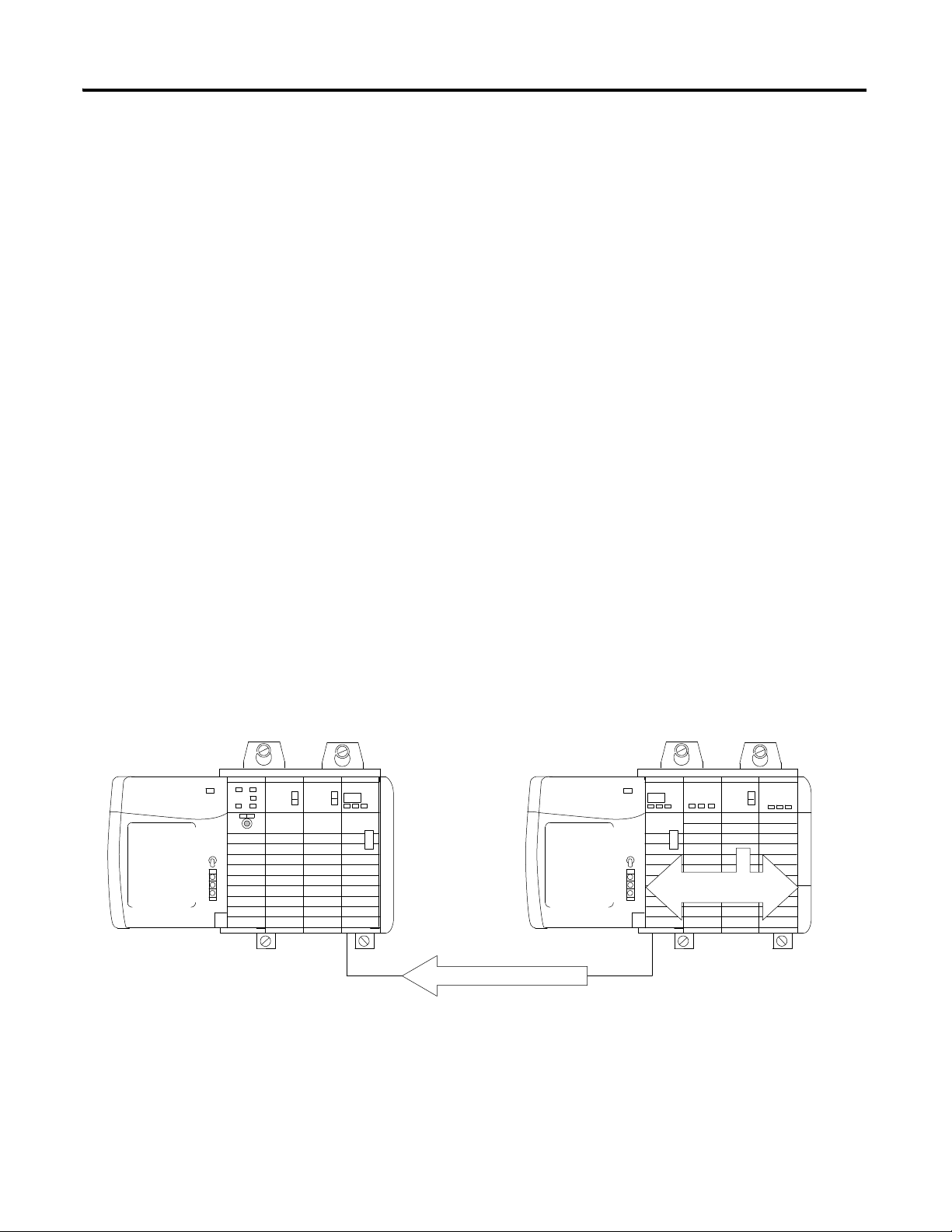
40949
Data sent from owner at the RPI
Owner-controller Output module
Output Module Operation
The RPI parameter governs exactly when an analog output module receives
data from the owner-controller and when the output module echoes data. An
owner-controller sends data to an analog output module only at the period
specified in the RPI. Data is not sent to the module at the end of the
controller’s program scan.
When an analog output module receives new data from an owner-controller
(that is, every RPI), the module automatically multicasts or ‘echoes’ a data
value that corresponds to the analog signal present at the output terminals to
the rest of the control system. This feature, called Output Data Echo, occurs
whether the output module is local or remote.
Depending on the value of the RPI, with respect to the length of the controller
program scan, the output module can receive and ‘echo’ data multiple times
during one program scan.
When the RPI is less than the program scan length, the controller effectively
allows the module’s output channels to change values multiple times during a
single program scan because the output module is not dependent on reaching
the end of the program to send data.
Output Modules in a Local Chassis
When specifying an RPI value for an analog output module, you instruct the
controller when to broadcast the output data to the module. If the module
resides in the same chassis as the owner-controller, the module receives the
data almost immediately after the controller sends it.
Publication 1756-UM009C-EN-P - December 2010 29
Page 30
Chapter 2 Analog I/O Operation in the ControlLogix System
ControlNet
Output data at least as often as RPI
Immediate backplane
transfers to module
Data sent from owner
at module’s RPI rate
Owner-controller ControlNet Bridge module ControlNet Bridge module Output module
41360
Output Modules in a Remote Chassis
If an output module resides in a remote chassis, the role of the RPI changes
slightly with respect to getting data from the owner-controller, depending on
what network type you are using to connect to the modules.
Remote Output Modules Connected Via the ControlNet Network
When remote analog output modules are connected to the owner-controller
via a scheduled ControlNet network, in addition to instructing the controller
to multicast the output data within its own chassis, the RPI also ‘reserves’ a
spot in the stream of data flowing across the ControlNet network.
The timing of this ‘reserved’ spot may or may not coincide with the exact value
of the RPI, but the control system will guarantee that the output module will
receive data at least as often as the specified RPI.
The ‘reserved’ spot on the network and when the controller sends the output
data are asynchronous to each other. This means there are best and worst case
scenarios as to when the module will receive the output data from the
controller in a networked chassis.
Best Case RPI Scenario
In the best case scenario, the controller sends the output data just before the
‘reserved’ network slot is available. In this case, the remotely-located output
module receives the data almost immediately.
30 Publication 1756-UM009C-EN-P - December 2010
Page 31

Analog I/O Operation in the ControlLogix System Chapter 2
IMPORTANT
Worst Case RPI Scenario
In the worst case scenario, the controller sends the data just after the ‘reserved’
network slot has passed. In this case, the module does not receive the data
until the next scheduled network slot.
These best and worst case scenarios indicate the time required
for output data to transfer from the controller to the module
once the controller has produced it.
The scenarios do not take into account when the module will
receive new data (updated by the user program) from the
controller. That is a function of the length of the user program
and its asynchronous relationship with the RPI.
Remote Output Modules Connected Via the EtherNet/IP Network
When remote analog output modules are connected to the owner-controller
via an EtherNet/IP network, the controller multicasts data in the
following ways:
• At the RPI, the owner-controller multicasts data within its own chassis.
• When the RPI timer expires or a programmed Immediate Output (IOT)
instruction is executed. An IOT sends data immediately and resets the
RPI timer.
Publication 1756-UM009C-EN-P - December 2010 31
Page 32

Chapter 2 Analog I/O Operation in the ControlLogix System
IMPORTANT
Listen-only Mode
Any controller in the system can listen to the data from any I/O module (that
is, input data or ‘echoed’ output data) even if the controller does not own the
module. In other words, the controller does not have to own a module’s
configuration data to listen to it.
During the I/O configuration process, you can specify one of several
‘Listen-Only’ modes in the Comm Format box on the New Module dialog
box. See
Choosing a ‘Listen-Only’ mode option allows the controller and module to
establish communications without the controller sending any configuration
data. In this instance, another controller owns the module being listened to.
page 205
for more Comm Format details.
If a ‘Listen-Only’ connection is being used by any controller to
the module, any connections over the Ethernet network cannot
use the Unicast option. See the Unicast box on
for details.
The ‘Listen-Only’ controller continues to receive multicast data
from the I/O module as long as a connection between an
owner-controller and I/O module is maintained
If the connection between all owner-controllers and the module
is broken, the module stops multicasting data and connections
to all ‘Listening controllers’ are also broken.
page 209
32 Publication 1756-UM009C-EN-P - December 2010
Page 33

Analog I/O Operation in the ControlLogix System Chapter 2
IMPORTANT
Input Module
Configuration
Data
Xxxxx
Xxxxx
Xxxxx
Input Module
Configuration
Data
Xxxxx
Xxxxx
Xxxxx
41056
Initial Configuration Initial Configuration
Controller A Controller BInput Module
AB
Multiple Owners of Input Modules
Because ‘Listening controllers’ lose their connections to modules when
communication with the owner stops, the ControlLogix system lets you define
more than one owner for input modules.
Only input modules can have multiple owners. If multiple
owners are connected to the same input module, they must
maintain identical configuration for that module.
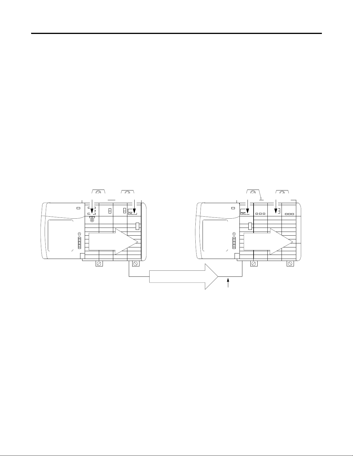
In the example below, Controller A and Controller B have both been
configured to be the owner of the input module.
When multiple controllers are configured to own the same input module, the
following events occur:
• When the controllers begin downloading configuration data, both try to
establish a connection with the input module.
• Whichever controller’s data arrives first establishes a connection.
• When the second controller’s data arrives, the module compares it to its
current configuration data (the data received and accepted from the first
controller).
– If the configuration data sent by the second controller matches the
configuration data sent by the first controller the connection is also
accepted.
– If any parameter of the second configuration data is different from
the first, the module rejects the connection; RSLogix 5000 software
alerts you to the rejected connection through an error message.
The advantage of multiple owners over a ‘Listen-only’ connection is that now
either of the controllers can lose the connection to the module and the module
will continue to operate and multicast data to the system because of the
connection maintained by the other owner-controller.
Publication 1756-UM009C-EN-P - December 2010 33
Page 34

Chapter 2 Analog I/O Operation in the ControlLogix System
Input Module
Configuration
Data
Xxxxx
Xxxxx
Xxxxx
Input Module
Configuration
Data
Xxxxx
Xxxxx
Xxxxx
41056
Modified Configuration Initial Configuration
Controller A Controller BInput Module
AB
Controller B is unaware that changes were made by Controller A.
IMPORTANT
Configuration Changes in an Input Module with Multiple Owners
You must be careful when changing an input module’s configuration data in a
multiple owner scenario. When the configuration data is changed in one of the
owners, for example, Controller A, and sent to the module, that configuration
data is accepted as the new configuration for the module. Controller B
continues to listen, unaware that any changes have been made in the module’s
behavior.
A pop-up screen in RSLogix 5000 software alerts you to the
possibility of a multiple owner situation and lets you inhibit the
connection before changing the module’s configuration. When
changing configuration for a module with multiple owners, we
recommend the connection be inhibited.
To prevent other owners from receiving potentially erroneous data, do the
following steps when changing a module’s configuration in a multiple
owner-controller scenario while online.
1. For each owner-controller, inhibit the controller’s connection to the
module, either in the software on the Connection tab or the pop-up
window warning of the multiple owner-controller condition.
2. Make the appropriate configuration data changes in the software. For
detailed information on using RSLogix 5000 software to change
configuration, see
3. Repeat
step 1
and
Chapter 10
step 2
.
for all owner-controllers, making the exact same
changes in all controllers.
4. Disable the Inhibit box in each owner’s configuration.
34 Publication 1756-UM009C-EN-P - December 2010
Page 35

Chapter
3
ControlLogix Analog I/O Module Features
Introduction
Common Analog I/O Features
This chapter describes features that are common to all ControlLogix analog
I/O modules.
ControlLogix analog input modules convert an analog signal of either volts,
millivolts, milliamps, or ohms that is connected to the module's screw
terminals into a digital value.
The digital value that represents the magnitude of the analog signal is then
transmitted on the backplane to either a controller or other control entities.
ControlLogix output modules convert a digital value that is delivered to the
module via the backplane into an analog signal of -10.5…10.5 volts
or 0…21 milliamps.
The digital value represents the magnitude of the desired analog signal. The
module converts the digital value into an analog signal and provides this signal
on the module's screw terminals.
The following table lists common features for analog I/O modules.
Feature Page
Removal and Insertion Under Power (RIUP) 36
Module Fault Reporting 36
Configurable Software 36
Electronic Keying 37
Access to System Clock for Timestamp Functions 44
Rolling Timestamp 44
Producer/Consumer Model 44
Status Indicator Information 45
Full Class I Division 2 Compliance 45
Agency Certification 45
Field Calibration 45
Sensor Offset 46
Latching of Alarms 46
Publication 1756-UM009C-EN-P - December 2010 35
Page 36

Chapter 3 ControlLogix Analog I/O Module Features
Removal and Insertion Under Power (RIUP)
All ControlLogix I/O modules can be inserted and removed from the chassis
while power is applied. This feature allows greater availability of the overall
control system because, while the module is being removed or inserted, there
is no additional disruption to the rest of the controlled process.
Module Fault Reporting
ControlLogix analog I/O modules provide both hardware and software
indication when a module fault has occurred. Each module has a status fault
indicator. RSLogix 5000 software graphically displays this fault and includes a
fault message that describes the nature of the fault. This feature lets you
determine how your module has been affected and what action should be
taken to resume normal operation.
For more information on module fault reporting as it relates to specific
modules, see the chapter describing that module, either chapter
4, 5, 6, 7
or 8.
Configurable Software
The RSLogix 5000 software uses a custom, easily understood interface to write
configuration. All module features are enabled or disabled through the I/O
configuration portion of the software.
You can also use the software to interrogate any module in the system to
retrieve:
• serial number.
• revision information.
• catalog number.
• vendor identification.
• error/fault information.
• diagnostic counters.
By eliminating such tasks as setting hardware switches and jumpers, the
software makes module configuration easier and more reliable.
36 Publication 1756-UM009C-EN-P - December 2010
Page 37

ControlLogix Analog I/O Module Features Chapter 3
Electronic Keying
The electronic keying feature automatically compares the expected module, as
shown in the RSLogix 5000 I/O Configuration tree, to the physical module
before I/O communication begins. You can use electronic keying to help
prevent communication to a module that does not match the type and revision
expected.
For each module in the I/O Configuration tree, the user-selected keying
option determines if, and how, an electronic keying check is performed.
Typically, three keying options are available.
• Exact Match
• Compatible Keying
• Disable Keying
You must carefully consider the benefits and implications of each keying
option when selecting between them. For some specific module types, fewer
options are available.
Electronic keying is based on a set of attributes unique to each product
revision. When a Logix5000 controller begins communicating with a module,
this set of keying attributes is considered.
Keying Attributes
Attribute Description
Vendor The manufacturer of the module, for example, Rockwell
Automation/Allen-Bradley.
Product Type The general type of the module, for example, communication
adapter, AC drive, or digital I/O.
Product Code The specific type of module, generally represented by its catalog
number, for example, 1756-IB16I.
Major Revision A number that represents the functional capabilities and data
exchange formats of the module. Typically, although not always, a
later, that is higher, Major Revision supports at least all of the data
formats supported by an earlier, that is lower, Major Revision of the
same catalog number and, possibly, additional ones.
Minor Revision A number that indicates the module’s specific firmware revision.
Minor Revisions typically do not impact data compatibility but may
indicate performance or behavior improvement.
You can find revision information on the General tab of a module’s Properties
dialog box.
Publication 1756-UM009C-EN-P - December 2010 37
Page 38

Chapter 3 ControlLogix Analog I/O Module Features
IMPORTANT
General Tab
Exact Match
Exact Match Keying requires all keying attributes, that is, Vendor, Product
Type, Product Code (catalog number), Major Revision, and Minor Revision, of
the physical module and the module created in the software to match precisely
to establish communication. If any attribute does not match precisely, I/O
communication is not permitted with the module or with modules connected
through it, as in the case of a communication module.
Changing electronic keying selections online may cause the I/O
communication connection to the module to be disrupted and
may result in a loss of data.
Use Exact Match keying when you need the system to verify that the module
revisions in use are exactly as specified in the project, such as for use in
highly-regulated industries. Exact Match keying is also necessary to enable
Automatic Firmware Update for the module via the Firmware Supervisor
feature from a Logix5000 controller.
38 Publication 1756-UM009C-EN-P - December 2010
Page 39

ControlLogix Analog I/O Module Features Chapter 3
EXAMPLE
IMPORTANT
Module Configuration
Vendor = Allen-Bradley
Product Type = Digital Input
Module
Catalog Number = 1756-IB16D
Major Revision = 3
Minor Revision = 1
Physical Module
Vendor = Allen-Bradley
Product Type = Digital Input
Module
Catalog Number = 1756-IB16D
Major Revision = 3
Minor Revision = 2
Communication is prevented
In the following scenario, Exact Match keying prevents I/O
communication:
• The module configuration is for a 1756-IB16D module with
module revision 3.1. The physical module is a 1756-IB16D module
with module revision 3.2. In this case, communication is
prevented because the Minor Revision of the module does not
match precisely.
Publication 1756-UM009C-EN-P - December 2010 39
Changing electronic keying selections online may cause the I/O
Communication connection to the module to be disrupted and
may result in a loss of data.
Compatible Keying
Compatible Keying indicates that the module determines whether to accept or
reject communication. Different module families, communication adapters,
and module types implement the compatibility check differently based on the
family capabilities and on prior knowledge of compatible products.
Compatible keying is the default setting. Compatible keying allows the physical
module to accept the key of the module configured in the software, provided
that the configured module is one the physical module is capable of emulating.
The exact level of emulation required is product and revision specific.
Page 40

Chapter 3 ControlLogix Analog I/O Module Features
EXAMPLE
Module Configuration
Vendor = Allen-Bradley
Product Type = Digital Input
Module
Catalog Number = 1756-IB16D
Major Revision = 3
Minor Revision = 3
Physical Module
Vendor = Allen-Bradley
Product Type = Digital Input
Module
Catalog Number = 1756-IB16D
Major Revision = 3
Minor Revision = 2
Communication is prevented
With Compatible keying, you can replace a module of a certain Major Revision
with one of the same catalog number and the same or later, that is higher,
Major Revision. In some cases, the selection makes it possible to use a
replacement that is a different catalog number than the original. For example,
you can replace a 1756-CNBR module with a 1756-CN2R module.
Release notes for individual modules indicate the specific compatibility details.
When a module is created, the module developers consider the module’s
development history to implement capabilities that emulate those of the
previous module. However, the developers cannot know future developments.
Because of this, when a system is configured, we recommend that you
configure your module by using the earliest, that is, lowest, revision of the
physical module that you believe will be used in the system. By doing this, you
can avoid the case of a physical module rejecting the keying request because it
is an earlier revision than the one configured in the software.
In the following scenario, Compatible keying prevents I/O
communication:
• The module configuration is for a 1756-IB16D module with
module revision 3.3. The physical module is a 1756-IB16D
module with module revision 3.2. In this case, communication is
prevented because the minor revision of the module is lower
than expected and may not be compatible with 3.3.
40 Publication 1756-UM009C-EN-P - December 2010
Page 41

ControlLogix Analog I/O Module Features Chapter 3
EXAMPLE
IMPORTANT
Module Configuration
Vendor = Allen-Bradley
Product Type = Digital Input
Module
Catalog Number = 1756-IB16D
Major Revision = 2
Minor Revision = 1
Physical Module
Vendor = Allen-Bradley
Product Type = Digital Input
Module
Catalog Number = 1756-IB16D
Major Revision = 3
Minor Revision = 2
Communication is allowed
In the following scenario, Compatible keying allows I/O
communication:
• The module configuration is for a 1756-IB16D module with
module revision 2.1. The physical module is a 1756-IB16D
module with module revision 3.2. In this case, communication is
allowed because the major revision of the physical module is
higher than expected and the module determines that it is
compatible with the prior major revision.
Publication 1756-UM009C-EN-P - December 2010 41
Changing electronic keying selections online may cause the I/O
communication connection to the module to be disrupted and
may result in a loss of data.
Page 42

Chapter 3 ControlLogix Analog I/O Module Features
ATTENTION
EXAMPLE
Module Configuration
Vendor = Allen-Bradley
Product Type = Digital Input
Module
Catalog Number = 1756-IA16
Major Revision = 3
Minor Revision = 1
Physical Module
Vendor = Allen-Bradley
Product Type = Analog Input
Module
Catalog Number = 1756-IF16
Major Revision = 3
Minor Revision = 2
Communication is prevented
Disabled Keying
Disabled Keying indicates the keying attributes are not considered when
attempting to communicate with a module. Other attributes, such as data size
and format, are considered and must be acceptable before I/O
communication is established. With Disabled keying, I/O communication may
occur with a module other than the type specified in the I/O Configuration
tree with unpredictable results. We generally do not recommend using
Disabled keying.
If you use Disabled keying, you must take full responsibility for understanding
whether the module being used can fulfill the functional requirements of the
application.
Be extremely cautious when using Disabled keying; if used
incorrectly, this option can lead to personal injury or death,
property damage, or economic loss.
In the following scenario, Disable keying prevents I/O
communication:
• The module configuration is for a 1756-IA16 digital input module.
The physical module is a 1756-IF16 analog input module. In this
case, communication is prevented because the analog
module rejects the data formats that the digital module
configuration requests.
42 Publication 1756-UM009C-EN-P - December 2010
Page 43

ControlLogix Analog I/O Module Features Chapter 3
EXAMPLE
IMPORTANT
Module Configuration
Vendor = Allen-Bradley
Product Type = Digital Input
Module
Catalog Number = 1756-IA16
Major Revision = 2
Minor Revision = 1
Physical Module
Vendor = Allen-Bradley
Product Type = Digital Input
Module
Catalog Number = 1756-IB16
Major Revision = 3
Minor Revision = 2
Communication is allowed
In the following scenario, Disable keying allows I/O
communication:
• The module configuration is for a 1756-IA16 digital input module.
The physical module is a 1756-IB16 digital input module. In this
case, communication is allowed because the two digital modules
share common data formats.
Publication 1756-UM009C-EN-P - December 2010 43
Changing electronic keying selections online may cause the I/O
communication connection to the module to be disrupted and
may result in a loss of data.
Page 44

Chapter 3 ControlLogix Analog I/O Module Features
Access to System Clock for Timestamp Functions
Controllers within the ControlLogix chassis maintain a system clock. This
clock is also known as the coordinated system time (CST). You can configure
your analog I/O modules to access this clock and timestamp input data or
output echo data when the module multicasts to the system. You decide how
to timestamp data when you choose a Communication Format on the New
Module dialog box. For more information, see
This feature provides accurate calculations between events to help you identify
the sequence of events in either fault conditions or in the course of normal
I/O operations. The system clock can be used between multiple modules in
the same chassis.
In systems using an EtherNet/IP network and 1588 Grand Master time, the
value of this timestamp still is the CST time. You must convert this CST value
to Grand Master time in the controller.
page 205
.
Rolling Timestamp
Each module maintains a rolling timestamp that is unrelated to the CST. The
rolling timestamp is a continuously running 15-bit timer that counts
in milliseconds.
For input modules, whenever a module scans its channels, it also records the
value of the rolling timestamp at that time. The user program can then use the
last two rolling timestamp values and calculate the interval between receipt of
data or the time when new data has been received.
For output modules, the rolling timestamp value is only updated when new
values are applied to the Digital to Analog Converter (DAC).
Producer/Consumer Model
By using the Producer/Consumer model, ControlLogix I/O modules can
produce data without having been polled by a controller first. The modules
produce the data and any owner or listen-only controller device can decide to
consume it.
For example, an input module produces data and any number of processors
can consume the data at the same time. This eliminates the need for one
processor to send the data to another processor.
44 Publication 1756-UM009C-EN-P - December 2010
Page 45

ControlLogix Analog I/O Module Features Chapter 3
IMPORTANT
Status Indicator Information
Each ControlLogix analog I/O module has status indicators on the front of
the module that lets you check the module health and operational status of
a module.
Status Description
Calibration Display indicates when your module is in the calibration mode.
Module Display indicates the module’s communication status.
For a list of status indicators and descriptions, see
on
page 273
.
Troubleshoot Your Module
Full Class I Division 2 Compliance
All ControlLogix analog I/O modules maintain CSA Class I Division 2 system
certification. This allows the ControlLogix system to be placed in an
environment other than only a 100% hazard free zone.
Modules should not be pulled under power, nor should a
powered RTB be removed, when a hazardous environment is
present.
Agency Certification
Any ControlLogix analog I/O modules that have obtained various agency
certifications are marked as such. Ultimately, all analog modules will have these
agency approvals and will be marked accordingly.
Field Calibration
ControlLogix analog I/O modules let you calibrate on a channel-by-channel or
module-wide basis. RSLogix 5000 software provides an interface to perform
calibration.
For calibration procedures, see
Publication 1756-UM009C-EN-P - December 2010 45
Chapter 11
on
page 233
.
Page 46

Chapter 3 ControlLogix Analog I/O Module Features
TIP
Sensor Offset
You can add this offset directly to the input or output during calibration
calculation. The purpose of this feature is to let you compensate for any sensor
offset errors which may exist, such offset errors are common in thermocouple
sensors.
To set a sensor offset, see
page 210
in
Chapter 10
.
Latching of Alarms
The latching feature allows analog I/O modules to latch an alarm in the set
position once it has been triggered, even if the condition causing the alarm to
occur disappears.
Data Format
During initial configuration of any ControlLogix analog I/O module, you
must choose a Communication Format. The format determines the data
format of data exchanged between the owner-controller and the I/O module.
For example, if you use an integer data format with the 1756-OF6CI module,
the clamping feature is not available for use.
Format type Description
Integer This mode uses a 16-bit signed format and allows faster
sampling rates while using less memory in the controller but
also limits the availability of features on your module.
The faster sampling rates and lower memory usage vary
according to module and application type. For more
information on the specific sampling rates, see the Module
Filter section in the module-specific chapters. Memory
usage can be up to 50% less than in floating point.
Floating point This mode uses a 32-bit IEEE floating point format and offers
all module features.
We recommend that you use the floating point data format in
most applications. Floating point is simpler to use. All
ControlLogix analog I/O modules default to floating point when
initialled configured.
You should use only the integer data format if your application
requires faster sampling rates than offered in floating point or if
your application memory is extremely limited.
46 Publication 1756-UM009C-EN-P - December 2010
Page 47

ControlLogix Analog I/O Module Features Chapter 3
IMPORTANT
Module Inhibiting
Module inhibiting lets you indefinitely suspend a connection between an
owner-controller and an analog I/O module. This process can occur in either
of the following ways:
• You write configuration for an I/O module but inhibit the module to
prevent it from communicating with the owner-controller. In this case,
the owner does not establish a connection and configuration is not sent
to the module until the connection is uninhibited.
• In your application, a controller already owns a module and has
downloaded configuration to the module and is currently exchanging
data over the connection between the devices. In this case, you can
inhibit the module and the owner-controller behaves as if the
connection to the module does not exist.
Whenever you inhibit an output module, it enters the Program
mode and all outputs change to the state configured for the
Program mode. For example, if an output module is configured
so that the state of the outputs go to zero (0) during Program
mode, whenever that module is inhibited, the outputs will go
to zero (0).
The following examples are instances where you may need to use module
inhibiting:
• Multiple controllers own the same analog input module. A change is
required in the module’s configuration; however, the change must be
made to the program in all controllers. In this case, you can:
a. Inhibit the module.
b. Change configuration in all controllers.
c. Uninhibit the module.
• You want to FLASH upgrade an analog I/O module. We recommend
you:
a. Inhibit the module.
b. Perform the upgrade.
c. Uninhibit the module.
• You are using a program that includes a module that you do not
physically possess yet, but you do not want the controller to continually
look for a module that does not exist yet. In this case, you can inhibit the
module in your program until it physically resides in the proper slot.
Publication 1756-UM009C-EN-P - December 2010 47
Page 48

Chapter 3 ControlLogix Analog I/O Module Features
65,536 counts
0 mA 21 mA
21 mA/65,536 counts ~ 0.34 μA/count
IMPORTANT
Relationship Between Module Resolution, Scaling, and Data Format
The following three concepts listed below are closely related and must be
explained in conjunction with each other.
Module Resolution
•
•
Scaling
•
Data Format as Related to Resolution and Scaling
Module Resolution
Resolution is the smallest amount of change that the module can detect.
Analog input modules are capable of 16-bit resolution. Output modules are
capable of 13…16 bit resolution, depending on the module type.
The 16 bits represent 65,536 counts. This total is fixed but the value of each
count is determined by the operational range you choose for your module.
For example, if you are using the 1756-IF6I module, your module’s available
current range equals 21 mA. Divide your range by the number of counts to
figure out the value of each count. In this case, one count is
approximately 0.34 µA.
Module Resolution
A module’s resolution is fixed. It will not change regardless of
what data format you choose or how you decide to scale your
module in floating point mode.
Resolution is based on the module hardware and the range
selected. If you use a sensor with limited range, you do not
change the module resolution.
48 Publication 1756-UM009C-EN-P - December 2010
Page 49

ControlLogix Analog I/O Module Features Chapter 3
IMPORTANT
The table lists the resolution for each module’s range.
Current Values Represented in Engineering Units
Module Range Number of
significant bits
1756-IF16 and
1756-IF8
1756-IF6CIS 0 mA…21 mA 16 bits 0.34 µA/count
1756-IF6I +/- 10.5V
1756-IR6I 1…487 Ω
1756-IT6I and
1756-IT6I2
1756-OF4 and
1756-OF8
1756-OF6VI +/- 10.5V 14 bits 1.3 mV
+/- 10.25V
0…10.25V
0…5.125V
0…20.5 mA
0…10.5V
0…5.25V
0…21 mA
2…1000 Ω
4…2000 Ω
8…4020 Ω
-12…30 mV
-12…78 mV
+/- 10.4V
0…21 mA
16 bits 320 µV/count
16 bits 343 µV/count
16 bits 7.7 MΩ/count
16 bits 0.7 µV/count
16 bits
15 bits
Resolution
160 µV/count
80 µV/count
0.32 µA/count
171 µV/count
86 µV/count
0.34 µA/count
15 MΩ/count
30 MΩ/count
60 MΩ/count
1.4 µV/count
320 µV/count
0.65 µA/count
1756-OF6CI 0…21 mA 13 bits 2.7 µA
Because these modules must allow for possible calibration
inaccuracies, resolution values represent the available
Analog to Digital or Digital to Analog counts over the
specified range.
Publication 1756-UM009C-EN-P - December 2010 49
Page 50

Chapter 3 ControlLogix Analog I/O Module Features
Module resolution
65,536 counts
0 mA 21 mA
4 mA 20 mA
0% in
engineering units
100% in
engineering units
Module scaling
Module scaling represents
the data returned from the
module to the controller
IMPORTANT
Scaling
With scaling, you change a quantity from one notation to another. For
ControlLogix analog I/O modules, scaling is only available with the
floating point data format.
When you scale a channel, you must choose two points along the module’s
operating range and apply low and high values to those points. For example, if
you are using the 1756-IF6I module in current mode, the module maintains a
0…21 mA range capability. But your application may use a 4…20 mA
transmitter. You can scale the module to represent 4 mA as the low signal and
20 mA as the high signal.
Scaling lets you configure the module to return data to the controller so that 4
mA returns a value of 0% in engineering units and 20 mA returns a value of
100% in engineering units.
Module Resolution Compared to Module Scaling
In choosing two points for the low and high value of your
application, you do not limit the range of the module. The
module’s range and its resolution remain constant regardless of
how you scale it for your application.
50 Publication 1756-UM009C-EN-P - December 2010
Page 51

ControlLogix Analog I/O Module Features Chapter 3
IMPORTANT
The module may operate with values beyond the 4…20 mA range. If an input
signal beyond the low and high signals is present at the module
(that is, 3 mA), that data will be represented in terms of the engineering units
set during scaling. The table shows example values that may appear based on
the example mentioned above.
Current Values Represented in Engineering Units
Current Engineering Units Value
3 mA -6.25%
4 mA 0%
12 mA 50%
20 mA 100%
21 mA 106.25%
Data Format as Related to Resolution and Scaling
You can choose one of the following data formats for your application:
• Integer mode
• Floating point mode
Integer mode
This mode provides the most basic representation of analog data. When a
module multicasts data in the integer mode, the low and high signals of the
input range are fixed.
Scaling is not available in integer mode. The low signal of your
application range equals -32,768 counts while the high signal
equals 32,767 counts.
Publication 1756-UM009C-EN-P - December 2010 51
Page 52

Chapter 3 ControlLogix Analog I/O Module Features
In integer mode, input modules generate digital signal values that correspond
to a range from -32,768…32,767 counts.
The table lists the conversions of a generated digital signal to the number
of counts.
Input Signal to User Count Conversion
Input Module Available
Range
1756-IF16/IF8 +/- 10V -10.25V
0…10V 0V
0…5V 0V
0…20 mA 0 mA
1756-IF6CIS 0…20 mA 0 mA
1756-IF6I +/- 10V -10.54688V
0…10V 0V
0…5V 0V
0…20 mA 0 mA
1756-IR6I 1…487 Ω 0.859068653Ω
2…1000 Ω 2 Ω
4…2000 Ω 4 Ω
8…4020 Ω 8 Ω
1756-IT6I and
1756-IT6I2
-12…30mV -15.80323 mV
-12…78mV -15.15836 mV
Low Signal and
User Counts
-32768 counts
-32768 counts
-32768 counts
-32768 counts
-32768 counts
-32768 counts
-32768 counts
-32768 counts
-32768 counts
-32768 counts
-32768 counts
-32768 counts
-32768 counts
-32768 counts
-32768 counts
High Signal and
User Counts
10.25V
32767 counts
10.25V
32767 counts
5.125V
32767 counts
20.58 mA
32767 counts
21.09376 mA
32767 counts
10.54688V
32767 counts
10.54688V
32767 counts
5.27344V
32767 counts
21.09376 mA
32767 counts
507.862Ω
32767 counts
1016.502 Ω
32767 counts
2033.780 Ω
32767 counts
4068.392 Ω
32767 counts
31.396 mV
32767 counts
79.241 mV
32767 counts
Output modules let you generate an analog signal at the screw terminals that
correspond to a range from -32,768…32,767 counts.
52 Publication 1756-UM009C-EN-P - December 2010
Page 53

ControlLogix Analog I/O Module Features Chapter 3
The table lists the conversions a generated digital signal to the number
of counts.
Output Signal to User Count Conversion
Output Module Available
Range
1756-OF4/OF8 0…20 mA 0 mA
+/- 10V -10.4336V
1756-OF6CI 0…20 mA 0 mA
1756-OF6VI +/- 10V -10.517V
Low Signal and
User Counts
-32768 counts
-32768 counts
-32768 counts
-32768 counts
High Signal and
User Counts
21.2916 mA
32767 counts
10.4336V
32767 counts
21.074 mA
32767 counts
10.517V
32767 counts
Floating point mode
This mode lets you change the data representation of the selected module.
Although the full range of the module does not change, you can scale your
module to represent I/O data in terms specific for your application.
For example, if you are using the 1756-IF6I module in floating point mode and
choose an input range of 0 mA…20 mA, the module can use signals within the
range of 0 mA…21 mA but you can scale the module to represent data
between 4 mA…20mA as the low and high signals in engineering units as
page 50
shown on
.
For an example of how to define data representation in engineering units
through RSLogix 5000 software, see
Publication 1756-UM009C-EN-P - December 2010 53
page 210
.
Page 54

Chapter 3 ControlLogix Analog I/O Module Features
Difference Between Integer and Floating Point
The key difference between choosing integer mode or floating point mode is
that the integer is fixed between -32,768…32,767 counts and floating point
mode provides scaling to represent I/O data in specific engineering units for
your application. Module resolution remains constant between the formats at
0.34 µA/count.
For example, the table shows the difference in the data returned from the
1756-IF6I module to the controller between data formats. In this case, the
module uses the 0 mA…20 mA input range with 0 mA scaled to 0%
and 20 mA scaled to 100%, as shown on page 50.
1756-IF6I Module using different data types
Signal Value Fixed Number of Counts
in Integer Mode
0 mA -32768 counts -25%
4 mA -20341 counts 0%
12 mA 4514 counts 50%
20 mA 29369 counts 100%
21.09376 mA 32767 counts 106.25%
Data Representation in Floating
Point Mode (Engineering Units)
54 Publication 1756-UM009C-EN-P - December 2010
Page 55

Chapter
4
Non-isolated Analog Voltage/Current Input Modules (1756-IF16, 1756-IF8)
Introduction
This chapter describes features specific to ControlLogix non-isolated, analog
voltage/current input modules.
Topic Page
Choose a Wiring Method 56
Choose a Data Format 58
Features Specific to Non-Isolated Analog Input Modules 59
Use Module Block and Input Circuit Diagrams 67
Wire the 1756-IF16 Module 70
Wire the 1756-IF8 Module 74
1756-IF16 Module Fault and Status Reporting 78
1756-IF8 Module Fault and Status Reporting 85
In addition to the features described in this chapter, the non-isolated analog
voltage/current input modules support all features described in
Chapter 3
voltage/current input modules support.
Additional Features for Non-Isolated Analog Input Modules
Feature Page
Removal and Insertion Under Power (RIUP) 36
. The table lists additional features that your non-isolated analog
Module Fault Reporting 36
Configurable Software 36
Electronic Keying 37
Access to System Clock for Timestamp Functions 44
Rolling Timestamp 44
Producer/Consumer Model 44
Status Indicator Information 45
Full Class I Division 2 Compliance 45
Agency Certification 45
Field Calibration 45
Sensor Offset 46
Latching of Alarms 46
Publication 1756-UM009C-EN-P - December 2010 55
Page 56

Chapter 4 Non-isolated Analog Voltage/Current Input Modules (1756-IF16, 1756-IF8)
Choose a Wiring Method
The 1756-IF16 and 1756-IF8 modules support these wiring methods:
•
Single-ended Wiring Method
•
Differential Wiring Method
•
High-speed Mode Differential Wiring Method
After determining the wiring method you will use on your module, you must
inform the system of that choice when you choose a
For more information,
For examples of each wiring format on the 1756-IF16 module, see the
examples beginning on
1756-IF8 module, see the examples beginning on
page 205
page 70
. For examples of each wiring format on the
Communication Format
page 74
.
.
Single-ended Wiring Method
Single-ended wiring compares one side of the signal input to signal ground.
This difference is used by the module in generating digital data for the
controller.
When using the single-ended wiring method, all input devices are tied to a
common ground. In addition to the common ground, the use of single-ended
wiring maximizes the number of usable channels on the module
(eight channels for the 1756-IF8 module and 16 channels for the 1756-IF16).
56 Publication 1756-UM0009C-EN-P - December 2010
Page 57

Non-isolated Analog Voltage/Current Input Modules (1756-IF16, 1756-IF8) Chapter 4
IMPORTANT
Differential Wiring Method
The differential wiring method is recommended for applications that may have
separate signal pairs or a common ground is not available. Differential wiring is
recommended for environments where improved noise immunity is needed.
This wiring method lets you use only half a module’s channels.
For example, you can use only eight channels on the
1756-IF16 module and four channels on the 1756-IF8 module.
In differential mode, the channels are not totally isolated from each other. If
multiple differential input signals have different voltage common references,
one channel could affect the reading of another channel. If this condition
cannot be avoided, then wire these inputs on different modules or replace the
non-isolated module with an isolated input module.
High-speed Mode Differential Wiring Method
You can configure the 1756-IF16 and 1756-IF8 modules for a high-speed
mode that will give you the fastest data updates possible. When using the
high-speed mode, remember these conditions:
• This mode uses the differential wiring method.
• This mode only allows use of one out of every four channels on the
module.
Update times for applications using the high-speed mode can be found on
page 60
.
Publication 1756-UM009C-EN-P - December 2010 57
Page 58

Chapter 4 Non-isolated Analog Voltage/Current Input Modules (1756-IF16, 1756-IF8)
IMPORTANT
Choose a Data Format
Data format determines the format of the data returned from the module to
the owner-controller and the features that are available to your application.
You choose a data format when you choose a
Communication Format
.
When you choose a Communication Format, you can select one of two data
formats:
• Integer mode
• Floating point mode
The table shows features that are available in each format.
Data Format Features Available Features Not Available
Integer mode Multiple input ranges
Module filter
Real time sampling
Floating point mode All features See below
Process alarms
Digital filtering
Rate alarms
Scaling
When using the 1756-IF16 module in single-ended mode (that
is, 16-channel mode) with a floating point data format, process
alarms and rate alarms are not available.
This condition exists when the 1756-IF16 is only wired for
single-ended mode. The 1756-IF8 is not affected.
58 Publication 1756-UM0009C-EN-P - December 2010
Page 59

Non-isolated Analog Voltage/Current Input Modules (1756-IF16, 1756-IF8) Chapter 4
Features Specific to Non-Isolated Analog Input Modules
The table lists features that are specific to the 1756-IF16 and
1756-IF8 modules.
Feature Page
Multiple Input Ranges 59
Module Filter 60
Real Time Sampling 61
Underrange/Overrange Detection 61
Digital Filter 62
Process Alarms 63
Rate Alarm 64
Wire Off Detection 64
Multiple Input Ranges
You can select from a series of operational ranges for each channel on your
module. The range designates the minimum and maximum signals that are
detectable by the module.
Module Possible Ranges
1756-IF16 and 1756-IF8 -10…10V
0…5V
0…10V
0…20 mA
See
page 210
for an example of how to choose an input range for your module.
Publication 1756-UM009C-EN-P - December 2010 59
Page 60

Chapter 4 Non-isolated Analog Voltage/Current Input Modules (1756-IF16, 1756-IF8)
IMPORTANT
Module Filter
The module filter is a built-in feature of the analog-to-digital convertor that
attenuates the input signal beginning at the specified frequency. This feature is
applied on a module-wide basis.
The module attenuates the selected frequency by approximately -3dB or 0.707
of the applied amplitude. This selected frequency is also called the bandwidth
of the module.
An input signal with frequencies above the selected frequency will be
attenuated more, while frequencies below the selection will receive no
attenuation.
In addition to frequency rejection, a by-product of the filter selection is the
minimum sample rate (RTS) that is available. For example, in floating point
mode, the 1000 Hz selection will not attenuate any frequencies less than
1000 Hz, but will allow sampling of all 16 channels within 18 ms. But the
10 Hz selection attenuates all frequencies above 10 Hz and allows only
sampling of all 16 channels within 488 ms.
The default setting for the module filter is 60 Hz. This setting
provides approximately 3 dB of filtering of a 60 Hz input.
Use the following table to choose a module filter setting.
Filter Selections with Associated Performance Data
Module Filter Setting
(1) (2)
(-3dB)
Minimum sample time (RTS)
Integer mode
Minimum sample time (RTS)
Floating point mode
Effective resolution 16 bits 16 bits 16 bits 14 bits 12 bits
(1)
For optimal 50…60 Hz noise rejection (>80dB), choose the 10 Hz filter.
(2)
Worst case setting time to 100% of a step change is double the RTS sample times.
Wiring Mode 10 Hz 50…60 Hz
(Default)
Single-ended
Differential
High-speed differential
Single-ended
Differential
High-speed differential
488 ms
244 ms
122 ms
488 ms
244 ms
122 ms
88 ms
44 ms
22 ms
88 ms
44 ms
22 ms
100 Hz 250 Hz 1000 Hz
56 ms
28 ms
14 ms
56 ms
28 ms
14 ms
28 ms
14 ms
7 ms
28 ms
14 ms
7 ms
16 ms
8 ms
5 ms
18 ms
11 ms
6 ms
60 Publication 1756-UM0009C-EN-P - December 2010
Page 61

Non-isolated Analog Voltage/Current Input Modules (1756-IF16, 1756-IF8) Chapter 4
IMPORTANT
Real Time Sampling
This parameter instructs the module how often to scan its input channels and
obtain all available data. After the channels are scanned, the module multicasts
that data. This feature is applied on a module-wide basis.
During module configuration, you specify a real time sampling (RTS) period
and a requested packet interval (RPI) period. Both of these features instruct
the module to multicast data, but only the RTS feature instructs the module to
scan its channels before multicasting.
Underrange/Overrange Detection
This alarm feature detects when the non-isolated input module is operating
beyond limits set by the input range. For example, if you are using the
1756-IF16 module in the 0V…10V input range and the module voltage
increases to 11V, the overrange detects this condition.
The table shows the input ranges of non-isolated input modules and the
lowest/highest signal available in each range before the module detects an
underrange/overrange condition.
Input Module Available Range Lowest Signal
in Range
1756-IF16 and
1756-IF8
+/- 10V
0V…10V
0V…5V
0 mA…20 mA
-10.25V
0V
0V
0 mA
Highest Signal
in Range
10.25V
10.25V
5.125V
20.58 mA
Be careful when ‘disabling all alarms’ on the channel because it
also disables the underrange/overrange detection feature. If
alarms are disabled, overrange/underrange is zero and the only
way you can discover a wire-off detection is from the input
value itself. If you need to detect a wire-off status, do not
‘disable all alarms’.
We recommend that you disable only unused channels so
extraneous alarm bits are not set.
Publication 1756-UM009C-EN-P - December 2010 61
Page 62

Chapter 4 Non-isolated Analog Voltage/Current Input Modules (1756-IF16, 1756-IF8)
Yn = Yn-1 + (Xn – Yn-1)
[Δ t]
Δ t + TA
Yn = Present output, filtered peak voltage (PV)
Yn-1 =Previous output, filtered PV
Δt = Module channel update time (seconds)
TA = Digital filter time constant (seconds)
Xn = Present input, unfiltered PV
0 0.01 0.5 0.99 Time in Seconds
16723
100%
63%
0
Amplitude
Unfiltered Input
TA = 0.01 sec
TA = 0.5 sec
TA = 0.99 sec
Digital Filter
The digital filter smooths input data noise transients for all channels on the
module. This feature is applied on a per channel basis.
The digital filter value specifies the time constant for a digital first order lag
filter on the input. It is specified in units of milliseconds. A value of 0 disables
the filter.
The digital filter equation is a classic first order lag equation.
Using a step input change to illustrate the filter response, as shown in the
illustration, you can see that when the digital filter time constant elapses,
63.2% of the total response is reached. Each additional time constant achieves
63.2% of the remaining response.
To see how to set the Digital Filter, see
page 210
.
62 Publication 1756-UM0009C-EN-P - December 2010
Page 63

Non-isolated Analog Voltage/Current Input Modules (1756-IF16, 1756-IF8) Chapter 4
IMPORTANT
43153
High high
Low low
Low
High
Alarm deadbands
High high alarm turns Off
High alarm remains On
High high alarm turns On
High alarm remains On
Normal input range
Low low alarms turns Off
Low alarm remains On
High alarm turns Off
Low low alarms turns On
Low alarm remains On
Low alarms turns OffLow alarms turns On
High alarm
turns On
Process Alarms
Process alarms alert you when the module has exceeded configured high or
low limits for each channel. You can latch process alarms. These are set at
four user configurable alarm trigger points.
•High high
• High
•Low
• Low low
Process alarms are not available in integer mode or in
applications using 1756-IF16 module in the single-ended,
floating point mode. The values for each limit are entered
in scaled engineering units.
Alarm Deadband
You may configure an alarm deadband to work with the process alarms. The
deadband allows the process alarm status bit to remain set, despite the alarm
condition disappearing, as long as the input data remains within the deadband
of the process alarm.
The illustration on the next page shows input data that sets each of the four
alarms at some point during module operation. In this example, latching is
disabled; therefore, each alarms turns Off when the condition that caused it to
set ceases to exist.
Publication 1756-UM009C-EN-P - December 2010 63
To see how to set Process Alarms, see
page 212
.
Page 64

Chapter 4 Non-isolated Analog Voltage/Current Input Modules (1756-IF16, 1756-IF8)
IMPORTANT
Rate Alarm
The rate alarm triggers if the rate of change between input samples for each
channel exceeds the specified trigger point for that channel.
Rate alarms are not available in integer mode or in applications
using 1756-IF16 module in the single-ended, floating point
mode. The values for each limit are entered in scaled
engineering units.
For example, if you set the 1756-IF16 module (with normal scaling in volts) to
a rate alarm of 1.0 V/S, the rate alarm will only trigger if the difference
between measured input samples changes at a rate > 1.0 V/S.
If the module’s RTS is 100 ms that is, sampling new input data every 100 ms)
and at time 0, the module measures 5.0 volts and at time 100 ms measures
5.08 V, the rate of change is (5.08V - 5.0V) / (100 mS) = 0.8 V/S. The rate
alarm would not set as the change is less than the trigger point of 1.0V/s.
If the next sample taken is 4.9V, the rate of change is (4.9V…5.08V)/
(100 mS)=-1.8V/S. The absolute value of this result is > 1.0V/S, so the rate
alarm will set. Absolute value is applied because rate alarm checks for the
magnitude of the rate of change being beyond the trigger point, whether a
positive or negative excursion.
Wire Off Detection
The 1756-IF16 and 1756-IF8 modules will alert you when a signal wire only
has been disconnected from one of its channels or the RTB has been removed
from the module. When a wire-off condition occurs for this module, two
events occur:
• Input data for that channel changes to a specific scaled value.
• A fault bit is set in the owner-controller that may indicate the presence
of a wire-off condition.
64 Publication 1756-UM0009C-EN-P - December 2010
Page 65

Non-isolated Analog Voltage/Current Input Modules (1756-IF16, 1756-IF8) Chapter 4
IMPORTANT
Because the 1756-IF16 and 1756-IF8 modules can be applied in voltage or
current applications, differences exist as to how a wire-off condition is
detected in each application.
Be careful when ‘disabling all alarms’ on the channel because it
also disables the underrange/overrange detection feature. If
alarms are disabled, overrange/underrange is zero and the only
way you can discover a wire-off detection is from the input
value itself. If you need to detect a wire-off status, do not
‘disable all alarms’.
We recommend that you disable only unused channels so
extraneous alarm bits are not set.
The table lists the differences that occur when a wire-off condition occurs in
various applications.
Wire-Off Conditions
When the Wire-Off
condition occurs
Single-ended Voltage
Applications
Single-Ended Current • Input data for that channel changes to the scaled value
Differential Voltage • Input data for that channel changes to the scaled value
These events occur
• Input data for odd numbered channels changes to the scaled
value associated with the underrange signal value of the
selected operational range in floating point mode (minimum
possible scaled value) or -32,767 counts in integer mode.
• The ChxUnderrange (x = channel number) tag is set to 1.
• Input data for even numbered channels changes to the scaled
value associated with the overrange signal value of the
selected operational range in floating point mode (maximum
possible scaled value) or 32,767 counts in integer mode.
• The ChxOverrange (x= channel number) tag
associated with the underrange signal value of the selected
operational range in floating point mode (minimum possible
scaled value) or -32,768 counts in integer mode.
• The ChxUnderrange (x= channel number) tag is set to 1.
associated with the overrange signal value of the selected
operational range in floating point mode (maximum possible
scaled value) or 32,768 counts in integer mode.
(1)
is set to 1.
• The ChxOverrange (x= channel number) tag is set to 1.
Publication 1756-UM009C-EN-P - December 2010 65
Page 66

Chapter 4 Non-isolated Analog Voltage/Current Input Modules (1756-IF16, 1756-IF8)
Wire-Off Conditions
When the Wire-Off
These events occur
condition occurs
Differential Current
Applications
• Input data for that channel changes to the scaled value
associated with the overrange signal value of the selected
operational range in floating point mode (minimum possible
scaled value) or -32,768 counts in integer mode.
• The ChxUnderrange (x=channel number) tag is set to 1.
In current applications, wire-off detection occurs for one of the
following reasons:
• Because the RTB has been disconnected from the module.
• Both the signal wire and the jumper wire have been
disconnected.
The module reacts with the same conditions as described in
differential voltage applications.
(1)
For more information about tags in the tag editor, see
Appendix B
.
66 Publication 1756-UM0009C-EN-P - December 2010
Page 67

Non-isolated Analog Voltage/Current Input Modules (1756-IF16, 1756-IF8) Chapter 4
DC-DC
Converter
16-bit A/D
Converter
RIUP
Circuit
43504
16-bit A/D
Converter
16-bit A/D
Converter
16-bit A/D
Converter
Vref
Opto
isolation
MicroController
Backplane
ASIC
Serial
EEPROM
FLASH
ROM
SRAM
System
+5V
Field Side Backplane Side
DC-DC
Shutdown
Circuit
Input Data
Configuration Data
Control
Channels 0…3
Channels 4…7
Channels 8…11
Channels 12…5
Details of the 1756-IF16 input
circuitry are on the following pages.
DC-DC
Converter
16-bit A/D
Converter
RIUP
Circuit
43494
16-bit A/D
Converter
Vref
Opto
isolation
Serial
EEPROM
FLASH
ROM
SRAM
System
+5V
Field Side Backplane Side
DC-DC
Shutdown
Circuit
Channels 0…3
Channels 4 …7
Details of the 1756-IF8 input
circuitry are on the following pages
MicroController
Backplane
ASIC
Input Data
Configuration Data
Control
Use Module Block and Input Circuit Diagrams
This section shows the 1756-IF16 and 1756-IF8 modules’ block diagrams and
input circuit diagrams.
1756-IF16 Module Block Diagram
Publication 1756-UM009C-EN-P - December 2010 67
1756-IF8 Module Block Diagram
Page 68

Chapter 4 Non-isolated Analog Voltage/Current Input Modules (1756-IF16, 1756-IF8)
43495
Single-ended Voltage Inputs
Differential Voltage Inputs
– 15V Note: Odd-numbered, single-ended channels
float to negative full scale when unconnected.
IN-0
i RTN-0
IN-1
i RTN-1
RTN
+
–
+ 15V
249 Ω 1/4 Watt
0.01 μF
Channel 0
16-bit
A/D
Converter
– 15V
20 MΩ
249 Ω 1/4 Watt
10 K 10 K
0.01 μF
Channel 1
V
20 MΩ
10 K 10 K
+
–
V
+
–
V
IN-0
i RTN-0
IN-1
i RTN-1
RTN
+ 15V
249 Ω 1/4 Watt
0.01 μF
Channel 0
16-bit
A/D
Converter
20 MΩ
249 Ω 1/4 Watt
10 K 10 K
0.01 μF
Channel 1
20 MΩ
10 K 10 K
Field-side Circuit Diagrams
The field-side circuit diagrams are the same for both the 1756-IF16 and
1756-IF8 modules.
1756-IF16 and 1756-IF8 Voltage Input Circuit
68 Publication 1756-UM0009C-EN-P - December 2010
Page 69

Non-isolated Analog Voltage/Current Input Modules (1756-IF16, 1756-IF8) Chapter 4
43496
Single-ended Current Inputs
Differential Current Inputs
– 15V
A
A
IN-0
i RTN-0
IN-1
i RTN-1
RTN
+ 15V
249 Ω 1/4 Watt
0.01 μF
Channel 0
16-bit
A/D
Converter
20 MΩ
249 Ω 1/4 Watt
10 K
10 K
0.01 μF
Channel 1
20 MΩ
10 K 10 K
2-Wire
Tra ns mi tt er
2-Wire
Tra ns mi tt er
i
i
– 15V
A
A
IN-0
i RTN-0
IN-1
i RTN-1
RTN
+ 15V
249 Ω 1/4 Watt
0.01 μF
Channel 0
16-bit
A/D
Converter
20 MΩ
249 Ω 1/4 Watt
10 K
10 K
0.01 μF
Channel 1
20 MΩ
10 K 10 K
2-Wire
Transmitter
i
Jumper
Jumper
Jumper
The A locations represent locations where
you can place additional loop devices
(strip chart recorders) in the current loop.
1756-IF16 and 1756-IF8 Current Input Circuit
Publication 1756-UM009C-EN-P - December 2010 69
Page 70

Chapter 4 Non-isolated Analog Voltage/Current Input Modules (1756-IF16, 1756-IF8)
+
-
+
-
40912-M
1
34
56
78
910
1112
1314
1516
1718
1920
2122
2324
2526
2728
2930
3132
33
3536
IN-0
IN-10
IN-1
IN-9
IN-2
IN-8
IN-5
IN-3
IN-6
RTN
IN-7
IN-4
IN-13
IN-12
IN-14
IN-11
RTN
i RTN-0
i RTN-7
i RTN-4
i RTN-6
i RTN-8
i RTN-9
i RTN-10
i RTN-11
RTN
i RTN-12
i RTN-13
RTN
i RTN-5
i RTN-1
i RTN-2
i RTN-3
IN-15
i RTN-14
i RTN-15
Shield Ground
Channel 0
Channel 3
Jumper Wires
i
i
A
NOTES:
1. Use the table when wiring your module in differential mode
2. All terminals marked RTN are connected internally.
3. A 249 Ω current loop resistor is located between IN-x and i RTN-x terminals.
4. If multiple (+) or multiple (-) terminals are tied together, connect that tie point to a RTN terminal to
maintain the module’s accuracy.
5. Place additional loop devices (strip chart recorders, so forth) at the A location in the current loop.
6. Do not connect more than two wires to any single terminal.
IMPORTANT: When operating in four channel, high-speed mode, only use channels 0, 2, 4 and 6.
Channel Terminals Channel Terminals
Channel 0 IN-0 (+), IN-1 (-) & i RTN-0 Channel 4 IN-8 (+), IN-9 (-) & i RTN-8
Channel 1 IN-2 (+), IN-3 (-) & i RTN-2 Channel 5 IN-10 (+), IN-11 (-) & i RTN-10
Channel 2 IN-4 (+), IN-5 (-) & i RTN-4 Channel 6 IN-12 (+), IN-13 (-) & i RTN-12
Channel 3 IN-6 (+), IN-7 (-) & i RTN-6 Channel 7 IN-14 (+), IN-15 (-) & i RTN-14
2-Wire
Tr an sm it te r
A
+
–
4-Wire
Transmitter
Shield Ground
Channel 6
i
A
2
34
User-provided
Loop Power
Device
Supply
Wire the 1756-IF16 Module
Current and voltage wiring examples for the 1756-IF16 module are shown on
the following pages.
1756-IF16 Differential Current Wiring Example.
70 Publication 1756-UM0009C-EN-P - December 2010
Page 71

Non-isolated Analog Voltage/Current Input Modules (1756-IF16, 1756-IF8) Chapter 4
40913-M
12
34
56
78
910
1112
1314
1516
1718
1920
2122
2324
2526
2728
2930
3132
3334
3536
IN-0
IN-10
IN-1
IN-9
IN-2
IN-8
IN-5
IN-3
IN-6
RTN
IN-7
IN-4
IN-13
IN-12
IN-14
IN-11
RTN
i RTN-0
i RTN-7
i RTN-4
i RTN-6
i RTN-8
i RTN-9
i RTN-10
i RTN-11
RTN
i RTN-12
i RTN-13
RTN
i RTN-5
i RTN-1
i RTN-2
i RTN-3
IN-15
i RTN-14
i RTN-15
Shield Ground
Shield Ground
Channel 0
Channel 3
+
–
+
–
NOTES:
1. Use the table when wiring your module in differential mode
2. All terminals marked RTN are connected internally.
3. If multiple (+) or multiple (-) terminals are tied together, connect that tie point to a RTN terminal
to maintain the module’s accuracy.
4. Terminals marked RTN or iRTN are not used for differential voltage wiring.
5. Do not connect more than two wires to any single terminal.
IMPORTANT: When operating in four channel, high-speed mode, only use channels 0, 2, 4 and 6.
Channel Terminals Channel Terminals
Channel 0 IN-0 (+) & IN-1 (-) Channel 4 IN-8 (+) & IN-9 (-)
Channel 1 IN-2 (+) & IN-3 (-) Channel 5 IN-10 (+) & IN-11 (-)
Channel 2 IN-4 (+) & IN-5 (-) Channel 6 IN-12 (+) & IN-13 (-)
Channel 3 IN-6 (+) & IN-7 (-) Channel 7 IN-14 (+) & IN-15 (-)
1756-IF16 Differential Voltage Wiring Example
Publication 1756-UM009C-EN-P - December 2010 71
Page 72

Chapter 4 Non-isolated Analog Voltage/Current Input Modules (1756-IF16, 1756-IF8)
+
-
12
34
56
78
910
1112
1314
1516
1718
1920
2122
2324
2526
2728
2930
3132
3334
3536
IN-0
IN-10
IN-1
IN-9
IN-2
IN-8
IN-5
IN-3
IN-6
RTN
IN-7
IN-4
IN-13
IN-12
IN-14
IN-11
RTN
i RTN-0
i RTN-7
i RTN-4
i RTN-6
i RTN-8
i RTN-9
i RTN-10
i RTN-11
RTN
i RTN-12
i RTN-13
RTN
i RTN-5
i RTN-1
i RTN-2
i RTN-3
IN-15
i RTN-14
i RTN-15
i
i
A
NOTES:
1. All terminals marked RTN are connected internally.
2. For current applications, all terminals marked iRTN must be wired to terminals marked RTN.
3. A 249 Ω current loop resistor is located between IN-x and i RTN-x terminals.
4. Place additional loop devices (strip chart recorders, so forth) at the A location in the current loop.
5. Do not connect more than two wires to any single terminal.
40914-M
Jumper Wires
2-Wire
Tra ns mi tt er
Shield Ground
User-provided
Loop Power
1756-IF16 Single-ended Current Wiring Example
72 Publication 1756-UM0009C-EN-P - December 2010
Page 73

Non-isolated Analog Voltage/Current Input Modules (1756-IF16, 1756-IF8) Chapter 4
40915-M
12
34
56
78
910
1112
1314
1516
1718
1920
2122
2324
2526
2728
2930
3132
3334
3536
IN-0
IN-10
IN-1
IN-9
IN-2
IN-8
IN-5
IN-3
IN-6
RTN
IN-7
IN-4
IN-13
IN-12
IN-14
IN-11
RTN
i RTN-0
i RTN-7
i RTN-4
i RTN-6
i RTN-8
i RTN-9
i RTN-10
i RTN-11
RTN
i RTN-12
i RTN-13
RTN
i RTN-5
i RTN-1
i RTN-2
i RTN-3
IN-15
i RTN-14
i RTN-15
Shield Ground
Shield Ground
+
–
+
–
NOTES:
1. All terminals marked RTN are connected internally.
2. Terminals marked iRTN are not used for single-ended voltage wiring.
3. Do not connect more than two wires to any single terminal.
1756-IF16 Single-ended Voltage Wiring Example
Publication 1756-UM009C-EN-P - December 2010 73
Page 74

Chapter 4 Non-isolated Analog Voltage/Current Input Modules (1756-IF16, 1756-IF8)
12
34
56
78
910
1112
1314
1516
1718
1920
2122
2324
2526
2728
2930
3132
3334
3536
IN-0
Not used
IN-1
Not used
IN-2
Not used
IN-5
IN-3
IN-6
RTN
IN-7
IN-4
Not used
Not used
Not used
Not used
RTN
i RTN-0
i RTN-7
i RTN-4
i RTN-6
Not used
Not used
Not used
Not used
RTN
Not used
Not used
RTN
i RTN-5
i RTN-1
i RTN-2
i RTN-3
Not used
Not used
Not used
+
-
Shield Ground
Channel 0
Channel 3
Jumper Wires
i
i
A
2-Wire
Tra ns mi tt er
A
NOTES:
1. Use the table when wiring your module in differential mode
2. All terminals marked RTN are connected internally.
3. A 249 Ω current loop resistor is located between IN-x and i RTN-x terminals.
4. If multiple (+) or multiple (-) terminals are tied together, connect that tie point to a RTN terminal to
maintain the module’s accuracy.
5. Place additional loop devices (strip chart recorders, so forth) at the A location in the current loop.
6. Do not connect more than two wires to any single terminal.
IMPORTANT: When operating in two channel, high-speed mode, only use channels 0 and 2.
Channel Terminals
Channel 0 IN-0 (+), IN-1 (-) & i RTN-0
Channel 1 IN-2 (+), IN-3 (-) & i RTN-2
Channel 2 IN-4 (+), IN-5 (-) & i RTN-4
Channel 3 IN-6 (+), IN-7 (-) & i RTN-6
40912-M
User-provided
Loop Power
Wire the 1756-IF8 Module
Current and voltage wiring examples for the 1756-IF8 module are shown on
the following pages.
1756-IF8 Differential Current Wiring Example - 4 channels.
74 Publication 1756-UM0009C-EN-P - December 2010
Page 75

Non-isolated Analog Voltage/Current Input Modules (1756-IF16, 1756-IF8) Chapter 4
Not used
Not used
Not used
Not used
Not used
Not used
Not used
RTN
Not used
Not used
Not used
Not used
RTN
Not used
Not used
Not used
Not used
Not used
12
34
56
78
910
1112
1314
1516
1718
1920
2122
2324
2526
2728
2930
3132
3334
3536
IN-0
IN-1
IN-2
IN-5
IN-3
IN-6
RTN
IN-7
IN-4
i RTN-0
i RTN-7
i RTN-4
i RTN-6
RTN
i RTN-5
i RTN-1
i RTN-2
i RTN-3
Shield Ground
Shield Ground
Channel 0
Channel 3
+
–
+
–
40913-M
NOTES:
1. Use the table when wiring your module in differential mode
2. All terminals marked RTN are connected internally.
3. If multiple (+) or multiple (-) terminals are tied together, connect that tie point to a RTN
terminal to maintain the module’s accuracy.
4. Terminals marked RTN or iRTN are not used for differential voltage wiring.
5. Do not connect more than two wires to any single terminal.
IMPORTANT: When operating in two channel, high-speed mode, only use channels 0 and 2.
Channel Terminals
Channel 0 IN-0 (+) & IN-1 (-)
Channel 1 IN-2 (+) & IN-3 (-)
Channel 2 IN-4 (+) & IN-5 (-)
Channel 3 IN-6 (+) & IN-7 (-)
1756-IF8 Differential Voltage Wiring Example - 4 Channels
Publication 1756-UM009C-EN-P - December 2010 75
Page 76

Chapter 4 Non-isolated Analog Voltage/Current Input Modules (1756-IF16, 1756-IF8)
12
34
56
78
910
1112
1314
1516
1718
1920
2122
2324
2526
2728
2930
3132
3334
3536
IN-0
IN-1
IN-2
IN-5
IN-3
IN-6
RTN
IN-7
IN-4
i RTN-0
i RTN-7
i RTN-4
i RTN-6
RTN
i RTN-5
i RTN-1
i RTN-2
i RTN-3
i
i
Not used
Not used
Not used
Not used
Not used
Not used
Not used
RTN
Not used
Not used
Not used
Not used
RTN
Not used
Not used
Not used
Not used
Not used
A
+
-
2-Wire
Transmitter
Shield Ground
Jumper Wires
NOTES:
1. All terminals marked RTN are connected internally.
2. For current applications, all terminals marked iRTN must be wired to terminals marked RTN.
3. A 249 Ω current loop resistor is located between IN-x and i RTN-x terminals.
4. Place additional loop devices (strip chart recorders, so forth) at the A location in the current loop.
5. Do not connect more than two wires to any single terminal.
User-provided
Loop Power
1756-IF8 Single-ended Current Wiring Example
76 Publication 1756-UM0009C-EN-P - December 2010
Page 77

Non-isolated Analog Voltage/Current Input Modules (1756-IF16, 1756-IF8) Chapter 4
40915-M
12
34
56
78
910
1112
1314
1516
1718
1920
2122
2324
2526
2728
2930
3132
3334
3536
IN-0
Not used
IN-1
Not used
IN-2
Not used
IN-5
IN-3
IN-6
RTN
IN-7
IN-4
Not used
Not used
Not used
Not used
RTN
I RTN-0
I RTN-7
I RTN-4
I RTN-6
Not used
Not used
Not used
Not used
RTN
Not used
Not used
RTN
I RTN-5
I RTN-1
I RTN-2
I RTN-3
Not used
Not used
Not used
Shield Ground
Shield Ground
+
–
+
–
NOTES:
1. All terminals marked RTN are connected internally.
2. Terminals marked iRTN are not used for single-ended voltage wiring.
3. Do not connect more than two wires to any single terminal.
1756-IF8 Single-ended Voltage Wiring Example
Publication 1756-UM009C-EN-P - December 2010 77
Page 78

Chapter 4 Non-isolated Analog Voltage/Current Input Modules (1756-IF16, 1756-IF8)
IMPORTANT
1756-IF16 Module Fault and Status Reporting
The 1756-IF16 module multicasts status and fault data to the owner/listening
controller with its channel data. The fault data is arranged in such a manner as
to let you choose the level of granularity for examining fault conditions.
Three levels of tags work together to provide an increasing degree of detail as
to the specific cause of faults on the module.
The table lists tags that can be examined in ladder logic to indicate when a fault
has occurred:
Tag Description
Module Fault
Word
Channel Fault
Word
Channel Status
Words
This word provides fault summary reporting. Its tag name is
ModuleFaults.
This word provides underrange, overrange and communication fault
reporting. Its tag name is ChannelFaults. When examining the Channel
Fault Word for faults, remember the following:
• 16 channels are used in single-ended wiring.
• Eight channels are used in differential wiring.
• Four channels are used in high-speed differential wiring.
• All bytes start with bit 0.
These words, one per channel, provide individual channel underrange
and overrange fault reporting for process alarms, rate alarms, and
calibration faults. Its tag name is ChxStatus.
Differences exist between floating point and integer modes as
they relate to module fault reporting. These differences are
explained in the following two sections.
78 Publication 1756-UM0009C-EN-P - December 2010
Page 79

Non-isolated Analog Voltage/Current Input Modules (1756-IF16, 1756-IF8) Chapter 4
Module Fault Word
(described on
page 80
)
Channel Fault Word
(described on
page 80
)
Channel Status Words
(one for each channel–described
on
page 81
)
15 14 13 12 11
543210
54321076
15 = AnalogGroupFault
10 = Calibrating
9 = Cal Fault
14, 13, 12, & 11 are not used
7 = Ch7Fault
6 = Ch6Fault
5 = Ch5Fault
4 = Ch4Fault
3 = Ch3Fault
2 = Ch2Fault
1 = Ch1Fault
0 = Ch0Fault
7 = ChxCalFault
6 = ChxUnderrange
5 = ChxOverrange
4 = ChxRateAlarm
If set, any bit in the Channel Fault word, also sets the Analog
Group Fault in the Module Fault word
A channel calibration fault
sets the calibration fault in
the Module Fault word
Alarm bits 0…4 in the Channel Status word
do not set additional bits at any higher level.
You must monitor these conditions here.
The number of channel status words is
dependent on the wiring format used.
3 = ChxLAlarm
2 = ChxHAlarm
1 = ChxLLAlarm
0 = ChxHHAlarm
An underrange, overrange condition
sets appropriate Channel Fault bits
When the module is calibrating, all
bits in the Channel Fault word are set
10 9
987615 14 13 12 11 10
15 = Ch15Fault
14 = Ch14Fault
13 = Ch13Fault
12 = Ch12Fault
11 = Ch11Fault
10 = Ch10Fault
9 = Ch9Fault
8 = Ch8Fault
16 channels used in S.E. wiring
Eight channels used in Diff. wiring
Four channels used in H.S. Diff.
wiring
41512
1756-IF16 Fault Reporting in
The illustration is an example of the fault reporting process for the 1756-IF16
module in floating point mode.
Floating Point Mode
Publication 1756-UM009C-EN-P - December 2010 79
Page 80

Chapter 4 Non-isolated Analog Voltage/Current Input Modules (1756-IF16, 1756-IF8)
1756-IF16 Module Fault Word Bits – Floating Point Mode
Bits in this word provide the highest level of fault detection. A non-zero
condition in this word reveals that a fault exists on the module. You can
examine further down to isolate the fault.
The table lists tags that can be examined in ladder logic to indicate when a fault
has occurred.
Tag Description
Analog Group
Fault
Calibrating This bit is set when any channel is being calibrated. When this bit is
Calibration Fault This bit is set when any of the individual Channel Calibration Fault bits
This bit is set when any bits in the Channel Fault word are set. Its tag
name is AnalogGroupFault.
set, all bits in the Channel Fault word are set. Its tag name is
Calibrating.
are set. Its tag name is CalibrationFault.
1756-IF16 Channel Fault Word Bits – Floating Point Mode
During normal module operation, bits in the Channel Fault word are set if any
of the respective channels has an Under or Overrange condition. Checking this
word for a non-zero value is a quick way to check for Under or Overrange
conditions on the module.
The table lists the conditions that set all Channel Fault word bits.
This condition sets all Channel
Fault word bits
A channel is being calibrated • ‘FFFF’ for single-ended operating mode
And causes the module to display the
following in the Channel Fault word bits
• ‘00FF’ for differential operating mode
• ‘000F’ for high-speed differential operating
mode
A communication fault occurred
between the module and its
owner-controller
‘FFFF’ for all bits, regardless of the application
Your logic can monitor the Channel Fault Word bit for a particular input to
determine the state of that point.
80 Publication 1756-UM0009C-EN-P - December 2010
Page 81

Non-isolated Analog Voltage/Current Input Modules (1756-IF16, 1756-IF8) Chapter 4
1756-IF16 Channel Status Word Bits – Floating Point Mode
Any of the Channel Status words, one for each channel, display a non-zero
condition if that particular channel has faulted for the conditions listed below.
Some of these bits set bits in other Fault words. When the Underrange or
Overrange bits (bits 6 and 5) in any of the words are set, the appropriate bit is
set in the Channel Fault word.
When the Calibration Fault bit (bit 7) is set in any of the words, the Calibration
Fault bit (bit 9) is set in the Module Fault word. The table lists the conditions
that set each of the word bits.
Tag (Status
Bit Event that sets this tag
word)
ChxCalFault 7 This bit is set if an error occurs during calibration for that channel, causing a
bad calibration. This bit also sets bit 9 in the Module Fault word.
Underrange 6 This bit is set when the input signal at the channel is less than or equal to the
minimum detectable signal. For more information on the minimum detectable
signal for each module, see
page 61
. This bit also sets the appropriate bit in
the Channel Fault word.
Overrange 5 This bit is set when the input signal at the channel is greater than or equal to
the maximum detectable signal. For more information on the maximum
detectable signal for each module, see on
page 61
. This bit also sets the
appropriate bit in the Channel Fault word.
ChxRateAlarm
(1)
4
This bit is set when the input channel’s rate of change exceeds the configured
Rate Alarm parameter. It remains set until the rate of change drops below the
configured rate. If latched, the alarm will remain set until it is unlatched.
ChxLAlarm
(1)
3
This bit is set when the input signal moves beneath the configured Low Alarm
limit. It remains set until the signal moves above the configured trigger point.
If latched, the alarm will remain set until it is unlatched. If a deadband is
specified, the alarm will also remain set as long as the signal remains within
the configured deadband.
ChxHAlarm
(1)
2
This bit is set when the input signal moves above the configured High Alarm
limit. It remains set until the signal moves below the configured trigger point.
If latched, the alarm will remain set until it is unlatched. If a deadband is
specified, the alarm will also remain set as long as the signal remains within
the configured deadband.
ChxLLAlarm
(1)
1
This bit is set when the input signal moves beneath the configured Low-Low
Alarm limit. It remains set until the signal moves above the configured trigger
point. If latched, the alarm will remain set until it is unlatched. If a deadband
is specified, the alarm will also remain latched as long as the signal remains
within the configured deadband.
ChxHHAlarm
(1)
0
This bit is set when the input signal moves above the configured High-High
Alarm limit. It remains set until the signal moves below the configured trigger
point. If latched, the alarm will remain set until it is unlatched. If a deadband
is specified, the alarm will also remain latched as long as the signal remains
within the configured deadband.
(1)
Bits 0…4 are not available in floating point, single-ended mode.
Publication 1756-UM009C-EN-P - December 2010 81
Page 82

Chapter 4 Non-isolated Analog Voltage/Current Input Modules (1756-IF16, 1756-IF8)
Module Fault Word
(described on
page 83
)
15 14 13 12 11 10 9
543210
0
15 = AnalogGroupFault
10 = Calibrating
9 = Cal Fault
14, 13, 12, & 11 are not used
31 = Ch0Underrange
30 = Ch0Overrange
29 = Ch1Underrange
28 = Ch1Overrange
27 = Ch2Underrange
26 = Ch2Overrange
25 = Ch3Underrange
24 = Ch3Overrange
41513
Underrange and overrange conditions
set the corresponding Channel Fault
word bit for that channel
When the module is
calibrating, all bits in the
Channel Fault word are set
If set, any bit in the Channel Fault word, also sets the Analog
Group Fault and Input Group Fault in the Module Fault word
A calibrating fault
sets bit 9 in the
Module Fault word
31
987615 14 13 12 11 10
7 = Ch7Fault
6 = Ch6Fault
5 = Ch5Fault
4 = Ch4Fault
3 = Ch3Fault
2 = Ch2Fault
1 = Ch1Fault
0 = Ch0Fault
15 = Ch15Fault
14 = Ch14Fault
13 = Ch13Fault
12 = Ch12Fault
11 = Ch11Fault
10 = Ch10Fault
9 = Ch9Fault
8 = Ch8Fault
16 channels used in S.E. wiring
8 channels used in Diff. wiring
4 channels used in H.S. Diff. wiring
All start at bit 0
23 = Ch4Underrange
22 = Ch4Overrange
21 = Ch5Underrange
20 = Ch5Overrange
19 = Ch6Underrange
18 = Ch6Overrange
17 = Ch7Underrange
16 = Ch7Overrange
15 = Ch8Underrange
14 = Ch8Overrange
13 = Ch9Underrange
12 = Ch9Overrange
11 = Ch10Underrange
10 = Ch10verrange
9 = C11Underrange
8 = Ch11Overrange
7 = Ch12Underrange
6 = Ch12Overrange
5 = Ch13Underrange
4 = Ch13Overrange
3 = Ch14Underrange
2 = Ch14Overrange
1 = Ch15Underrange
0 = Ch15Overrange
16 channels used in S.E. wiring
Eight channels used in Diff. wiring
Four channels used in H.S. Diff. wiring
All start at bit 31
Channel Fault Word
(described on
page 83
)
Channel Status Words
(described on
page 84
)
1756-IF16 Fault Reporting in Integer Mode
The illustration is an example of the fault reporting process for the 1756-IF16
module in integer mode.
82 Publication 1756-UM0009C-EN-P - December 2010
Page 83

Non-isolated Analog Voltage/Current Input Modules (1756-IF16, 1756-IF8) Chapter 4
1756-IF16 Module Fault Word Bits – Integer Mode
In integer mode, Module Fault word bits (bits 15…8) operate exactly as
described in floating point mode. The table lists tags that can be examined in
ladder logic to indicate when a fault has occurred:
Tag Description
Analog Group
Fault
Calibrating This bit is set when any channel is being calibrated. When this bit is
Calibration Fault This bit is set when any of the individual Channel Calibration Fault bits
This bit is set when any bits in the Channel Fault word are set. Its tag
name is AnalogGroupFault.
set, all bits in the Channel Fault word are set. Its tag name is
Calibrating.
are set. Its tag name is CalibrationFault.
1756-IF16 Channel Fault Word Bits – Integer Mode
In integer mode, Channel Fault word bits operate exactly as described in
floating point mode. The table lists the conditions that set all Channel Fault
word bits:
This condition sets all Channel
Fault word bits
A channel is being calibrated • ‘FFFF’ for single-ended operating mode
And causes the module to display the
following in the Channel Fault word bits
• ‘00FF’ for differential operating mode
• ‘000F’ for high-speed differential operating
mode
A communications fault occurred
between the module and its
owner-controller
‘FFFF’ for all bits, regardless of the application
Your logic can monitor the Channel Fault Word bit for a particular input to
determine the state of that point.
Publication 1756-UM009C-EN-P - December 2010 83
Page 84

Chapter 4 Non-isolated Analog Voltage/Current Input Modules (1756-IF16, 1756-IF8)
1756-IF16 Channel Status Word Bits – Integer Mode
The Channel Status word has these differences when the 1756-IF16 module is
used in integer mode.
• Only Underrange and Overrange conditions are reported by the
module.
• Alarming and Calibration Fault activities are not available, although the
Calibration Fault bit in the Module Fault word activates if a channel is
not properly calibrated.
• There is one, 32-bit Channel Status word for all 16 channels.
When the Calibration Fault bit (bit 7) is set in any of the words, the Calibration
Fault bit (bit 9) is set in the Module Fault word. The table lists the conditions
that set each of the words.
Tag (Status
word)
ChxUnderrange Odd-numbered bits from
ChxOverrange Even-numbered bits from
Bit Event that sets this tag
31…1 ( bit 31 represents
channel 0).
For a full listing of the
channels these bits
represent, see
30 …0 (bit 30 represents
channel 0).
For a full listing of the
channels these bits
represent, see on
page 82
page 82
.
The underrange bit is set when the input signal at the channel is less than or
equal to the minimum detectable signal.
For more information on the minimum detectable signal for each module, see
page 61
. This bit also sets the appropriate bit in the Channel Fault word.
The overrange bit is set when the input signal at the channel is greater than
or equal to the maximum detectable signal.
For more information on the maximum detectable signal for each module, see
page 61
. This bit also sets the appropriate bit in the Channel Fault word.
.
84 Publication 1756-UM0009C-EN-P - December 2010
Page 85

Non-isolated Analog Voltage/Current Input Modules (1756-IF16, 1756-IF8) Chapter 4
IMPORTANT
1756-IF8 Module Fault and Status Reporting
The 1756-IF8 module multicasts status and fault data to the owner/listening
controller with its channel data. The fault data is arranged in such a manner as
to let you choose the level of granularity for examining fault conditions.
Three levels of tags work together to provide an increasing degree of detail as
to the specific cause of faults on the module.
The table lists tags that can be examined in ladder logic to indicate when a fault
has occurred:
Tag Description
Module Fault
Word
Channel Fault
Word
Channel Status
Words
This word provides fault summary reporting. Its tag name is
ModuleFaults.
This word provides underrange, overrange and communication fault
reporting. Its tag name is ChannelFaults. When examining the Channel
Fault Word for faults, remember the following:
• Eight channels are used in single-ended wiring.
• Four channels are used in differential wiring.
• Two channels are used in high-speed differential wiring.
• All bytes start with bit 0.
These words, one per channel, provide individual channel underrange
and overrange fault reporting for process alarms, rate alarms, and
calibration faults. Its tag name is ChxStatus.
Differences exist between floating point and integer modes as
they relate to module fault reporting. These differences are
explained in the following two sections.
Publication 1756-UM009C-EN-P - December 2010 85
Page 86

Chapter 4 Non-isolated Analog Voltage/Current Input Modules (1756-IF16, 1756-IF8)
15 14 13 12 11
543210
54321076
15 = AnalogGroupFault
10 = Calibrating
9 = Cal Fault
14, 13, 12, and 11 are
not used
7 = Ch7Fault
6 = Ch6Fault
5 = Ch5Fault
4 = Ch4Fault
3 = Ch3Fault
2 = Ch2Fault
1 = Ch1Fault
0 = Ch0Fault
7 = ChxCalFault
6 = ChxUnderrange
5 = ChxOverrange
4 = ChxRateAlarm
41514
If set, any bit in the Channel Fault word, also sets the
Analog Group Fault in the Module Fault word
A channel calibration fault
sets the calibration fault in
the Module Fault word
3 = ChxLAlarm
2 = ChxHAlarm
1 = ChxLLAlarm
0 = ChxHHAlarm
An underrange, overrange condition
sets appropriate Channel Fault bits
When the module is calibrating, all
bits in the Channel Fault word are set
10 9
76
Eight channels used in S.E. wiring
Four channels used in Diff. wiring
Two channels used in H.S. Diff. wiring
All start at bit 0
Alarm bits 0…4 in the Channel Status word
do not set additional bits at any higher level.
You must monitor these conditions here.
The number of channel status words is
dependent on the communication
method used
Module Fault Word
(described on
page 87
)
Channel Fault Word
(described on
page 87
)
Channel Status Words
(One for each channel–described
on
page 88
)
1756-IF8 Fault Reporting in Floating Point Mode
The illustration describes the fault reporting process for the 1756-IF8 module
in floating point mode.
86 Publication 1756-UM0009C-EN-P - December 2010
Page 87

Non-isolated Analog Voltage/Current Input Modules (1756-IF16, 1756-IF8) Chapter 4
1756-IF8 Module Fault Word Bits – Floating Point Mode
Bits in this word provide the highest level of fault detection. A non-zero
condition in this word reveals that a fault exists on the module. You can
examine further down to isolate the fault.
The table lists tags that can be examined in ladder logic to indicate when a fault
has occurred:
Tag Description
Analog Group
Fault
Calibrating This bit is set when any channel is being calibrated. When this bit is
Calibration Fault This bit is set when any of the individual Channel Calibration Fault bits
This bit is set when any bits in the Channel Fault word are set. Its tag
name is AnalogGroupFault.
set, all bits in the Channel Fault word are set. Its tag name is
Calibrating.
are set. Its tag name is CalibrationFault.
1756-IF8 Channel Fault Word Bits – Floating Point Mode
During normal module operation, bits in the Channel Fault word are set if any
of the respective channels has an Under or Overrange condition. Checking this
word for a non-zero value is a quick way to check for Under or Overrange
conditions on the module.
The table lists the conditions that set all Channel Fault word bits:
This condition sets all Channel
Fault word bits
A channel is being calibrated • ‘00FF’ for single-ended wiring applications
And causes the module to display the
following in the Channel Fault word bits
• ‘000F’ for differential wiring applications
• ‘0003’ for high speed differential wiring
applications
A communication fault occurred
between the module and its
owner-controller
‘FFFF’ for all bits, regardless of the application
Your logic can monitor the Channel Fault Word bit for a particular input to
determine the state of that point.
Publication 1756-UM009C-EN-P - December 2010 87
Page 88

Chapter 4 Non-isolated Analog Voltage/Current Input Modules (1756-IF16, 1756-IF8)
1756-IF8 Channel Status Word Bits – Floating Point Mode
Any of the Channel Status words, one for each channel, will display a non-zero
condition if that particular channel has faulted for the conditions listed below.
Some of these bits set bits in other Fault words. When the Underrange and
Overrange bits (bits 6…5) in any of the words are set, the appropriate bit is set
in the Channel Fault word.
When the Calibration Fault bit (bit 7) is set in any of the words, the Calibration
Fault bit (bit 9) is set in the Module Fault word. The table lists the conditions
that set each of the word bits.
Tag (Status
word)
ChxCalFault 7 This bit is set if an error occurs during calibration for that channel, causing a
Underrange 6 This bit is set when the input signal at the channel is less than or equal to the
Overrange 5 This bit is set when the input signal at the channel is greater than or equal to
ChxRateAlarm 4 This bit is set when the input channel’s rate of change exceeds the configured
ChxLAlarm 3 This bit is set when the input signal moves beneath the configured Low Alarm
ChxHAlarm 2 This bit is set when the input signal moves above the configured High Alarm
ChxLLAlarm 1 This bit is set when the input signal moves beneath the configured Low-Low
ChxHHAlarm 0 This bit is set when the input signal moves above the configured High-High
Bit Event that sets this tag
bad calibration. This bit also sets bit 9 in the Module Fault word.
minimum detectable signal. For more information on the minimum detectable
signal for each module, see
the Channel Fault word.
the maximum detectable signal. For more information on the maximum
detectable signal for each module, see
appropriate bit in the Channel Fault word.
Rate Alarm parameter. It remains set until the rate of change drops below the
configured rate. If latched, the alarm will remain set until it is unlatched.
limit. It remains set until the signal moves above the configured trigger point.
If latched, the alarm will remain set until it is unlatched. If a deadband is
specified, the alarm will also remain set as long as the signal remains within
the configured deadband.
limit. It remains set until the signal moves below the configured trigger point.
If latched, the alarm will remain set until it is unlatched. If a deadband is
specified, the alarm will also remain set as long as the signal remains within
the configured deadband.
Alarm limit. It remains set until the signal moves above the configured trigger
point. If latched, the alarm will remain set until it is unlatched. If a deadband
is specified, the alarm will also remain latched as long as the signal remains
within the configured deadband.
Alarm limit. It remains set until the signal moves below the configured trigger
point. If latched, the alarm will remain set until it is unlatched. If a deadband
is specified, the alarm will also remain latched as long as the signal remains
within the configured deadband.
page 61
. This bit also sets the appropriate bit in
page 61
. This bit also sets the
88 Publication 1756-UM0009C-EN-P - December 2010
Page 89

Non-isolated Analog Voltage/Current Input Modules (1756-IF16, 1756-IF8) Chapter 4
15 14 13 12 11 10 9
543210
0
15 = AnalogGroupFault
10 = Calibrating
9 = Cal Fault
14, 13, 12, & 11 are not
used by 1756-IF8
31 = Ch0Underrange
30 = Ch0Overrange
29 = Ch1Underrange
28 = Ch1Overrange
27 = Ch2Underrange
26 = Ch2Overrange
25 = Ch3Underrange
24 = Ch3Overrange
41515
Underrange and overrange conditions
set the corresponding Channel Fault
word bit for that channel
When the module is
calibrating, all bits in the
Channel Fault word are set
If set, any bit in the Channel Fault word, also sets the Analog
Group Fault and Input Group Fault in the Module Fault word
A calibrating fault
sets bit 9 in the
Module Fault word
31
76
7 = Ch7Fault
6 = Ch6Fault
5 = Ch5Fault
4 = Ch4Fault
8 channels used in S.E. wiring
4 channels used in Diff. wiring
2 channels used in H.S. Diff. wiring
All start at bit 0
23 = Ch4Underrange
22 = Ch4Overrange
21 = Ch5Underrange
20 = Ch5Overrange
19 = Ch6Underrange
18 = Ch6Overrange
17 = Ch7Underrange
16 = Ch7Overrange
Eight channels used in S.E. wiring
Four channels used in Diff. wiring
Two channels used in H.S. Diff. wiring
All start at bit 31
Module Fault Word
(described on
page 90
)
Channel Fault Word
(described on
page 90
)
Channel Status Words
(described on
page 88
)
3 = Ch3Fault
2 = Ch2Fault
1 = Ch1Fault
0 = Ch0Fault
1756-IF8 Fault Reporting in Integer Mode
The illustration is an example of the fault reporting process for the 1756-IF8
module in integer mode.
Publication 1756-UM009C-EN-P - December 2010 89
Page 90

Chapter 4 Non-isolated Analog Voltage/Current Input Modules (1756-IF16, 1756-IF8)
1756-IF8 Module Fault Word Bits – Integer Mode
In integer mode, Module Fault word bits (bits 15…8) operate exactly as
described in floating point mode. The table lists tags that can be examined in
ladder logic to indicate when a fault has occurred:
Tag Description
Analog Group
Fault
Calibrating This bit is set when any channel is being calibrated. When this bit is
Calibration Fault This bit is set when any of the individual Channel Calibration Fault bits
This bit is set when any bits in the Channel Fault word are set. Its tag
name is AnalogGroupFault.
set, all bits in the Channel Fault word are set. Its tag name is
Calibrating.
are set. Its tag name is CalibrationFault.
1756-IF8 Channel Fault Word Bits – Integer Mode
In integer mode, Channel Fault word bits operate exactly as described in
floating point mode. The table lists the conditions that set all Channel Fault
word bits:
This condition sets all Channel
Fault word bits
A channel is being calibrated • ‘00FF’ for single-ended wiring applications
And causes the module to display the
following in the Channel Fault word bits
• ‘000F’ for differential wiring applications
• ‘0003’ for high-speed differential wiring
applications
A communications fault occurred
between the module and its
owner-controller
90 Publication 1756-UM0009C-EN-P - December 2010
‘FFFF’ for all bits, regardless of the application
Page 91

Non-isolated Analog Voltage/Current Input Modules (1756-IF16, 1756-IF8) Chapter 4
1756-IF8 Channel Status Word Bits – Integer Mode
The Channel Status word has the following differences when the 1756-IF16
module is used in integer mode:
• Only Underrange and Overrange conditions are reported by the
module.
• Alarming and Calibration Fault activities are not available, although the
Calibration Fault bit in the Module Fault word activates if a channel is
not properly calibrated.
• There is one, 32-bit Channel Status word for all eight channels.
When the Calibration Fault bit (bit 7) is set in any of the words, the Calibration
Fault bit (bit 9) is set in the Module Fault word. The table lists the conditions
that set each of the words.
Tag (Status
word)
ChxUnderrange Odd-numbered bits from
ChxOverrange Even-numbered bits from
Bit Event that sets this tag
31…1 ( bit 31 represents
channel 17).
For a full listing of the
channels these bits
represent, see on
30…16 ( bit 30 represents
channel 0).
For a full listing of the
channels these bits
represent, see on page 91.
page 88
The underrange bit is set when the input signal at the channel is less than or
equal to the minimum detectable signal.
For more information on the minimum detectable signal for each module, see
page 61. This bit also sets the appropriate bit in the Channel Fault word.
.
The overrange bit is set when the input signal at the channel is greater than
or equal to the maximum detectable signal.
For more information on the maximum detectable signal for each module, see
page 61
. This bit also sets the appropriate bit in the Channel Fault word.
Publication 1756-UM009C-EN-P - December 2010 91
Page 92

Chapter 4 Non-isolated Analog Voltage/Current Input Modules (1756-IF16, 1756-IF8)
Notes:
92 Publication 1756-UM0009C-EN-P - December 2010
Page 93

Chapter
IMPORTANT
5
Sourcing Current Loop Input Module (1756-IF6CIS) and Isolated Analog Voltage/Current Input Module (1756-IF6I)
Introduction
This chapter describes features specific to the ControlLogix isolated analog
voltage/current input module and the ControlLogix sourcing current loop
input module..
Topic Page
Use the Isolated Power Source on the 1756-IF6CIS 94
Choose a Data Format 95
Features Specific to the 1756-IF6I and 1756-IF6CIS Modules 96
Use Module Block and Input Circuit Diagrams 104
Wire the 1756-IF6CIS Module 106
Wire the 1756-IF6I Module 109
1756-IF6CIS or 1756-IF6I Module Fault and Status Reporting 111
The 1756-IF6CIS and 1756-IF6I modules primarily operate the
same with a few exceptions, including:
• The 1756-IF6CIS only operates in current mode.
• The 1756-IF6CIS offers an isolated power source for each
channel that supplies power to external transmitters.
The differences on the 1756-IF6CIS module are described on
page 94
.
With a few noted exceptions included in the descriptions, the
rest of the features described in this chapter apply to
both modules.
Publication 1756-UM009C-EN-P - December 2010 93
Page 94

Chapter 5 Sourcing Current Loop Input Module (1756-IF6CIS) and Isolated Analog Voltage/Current Input Module (1756-IF6I)
Use the Isolated Power Source on the 1756-IF6CIS
The 1756-IF6CIS module offers an internal power source on each channel.
The source is current limited to 28 mA and allows the module to power a
two-wire transmitter directly without the need for an external power supply.
The transmitter can then vary the current to the analog input in proportion to
the process variable being measured. The inclusion of an internal on-board
current source saves you the expense of extra power supplies and greatly
simplifies the interface wiring to field devices.
In addition to supplying loop power to two-wire transmitters, the module can
also accommodate current loops powered by an external supply and loops
using four-wire transmitters.
Power Calculations with the 1756-IF6CIS Module
The 1756-IF6CIS module uses the system power supply (1756-Px7x) as the
source for loop power. Because of the demands placed on that supply (that is,
the 1756-IF6CIS module consumes 7.9 W of backplane power), special care
must be taken when calculating the power requirements for modules in the
same chassis as a 1756-IF6CIS module.
For example, when used with the 1756-L55M13 controller, you can place only
eight 1756-IF6CIS modules in the chassis before exceeding the wattage
capacity of the power supply.
Other Devices in the Wiring Loop
The voltage source on each channel can drive loop impedance of up to
1000 ohms. This lets you include other devices, such as chart recorders and
meters, in the current loop.
For more information on wiring the 1756-IF6CIS module, see
page 106
.
94 Publication 1756-UM009C-EN-P - December 2010
Page 95

Sourcing Current Loop Input Module (1756-IF6CIS) and Isolated Analog Voltage/Current Input Module (1756-IF6I) Chapter 5
The 1756-IF6CIS and 1756-IF6I modules also support features described in
Chapter 3
Feature Page
Removal and Insertion Under Power (RIUP) 36
Module Fault Reporting 36
Configurable Software 36
Electronic Keying 37
Access to System Clock for Timestamp Functions 44
Rolling Timestamp 44
Producer/Consumer Model 44
Status Indicator Information 45
Full Class I Division 2 Compliance 45
Agency Certification 45
Sensor Offset 46
Latching of Alarms 46
. See the table for some of these features.
Choose a Data Format
Data format determines the format of the data returned from the module to
the owner-controller and the features that are available to your application.
You choose a data format when you choose a
Communication Format
.
You can choose one of these data formats:
• Integer mode
• Floating point mode
The table shows features that are available in each format.
Data Format Features Available Features Not Available
Integer mode Multiple input ranges
Notch filter
Real time sampling
Floating point mode All features N/A
For details on input and output data formats, see
Digital filtering
Process alarms
Rate alarms
Scaling
page 205
in
Chapter 10
.
Publication 1756-UM009C-EN-P - December 2010 95
Page 96

Chapter 5 Sourcing Current Loop Input Module (1756-IF6CIS) and Isolated Analog Voltage/Current Input Module (1756-IF6I)
Features Specific to the 1756-IF6I and 1756-IF6CIS Modules
The table lists features that are specific to the 1756-IF6CIS and 1756-IF6I
modules. Each feature is described later in this section.
Feature Page
Multiple Input Ranges
Notch Filter 97
Real Time Sampling 98
Underrange/Overrange Detection 98
Digital Filter 99
Process Alarms 100
Rate Alarm 101
Wire Off Detection 102
(1)
Only the 1756-IF6I offers multiple input ranges. The 1756-IF6CIS module
only operates in the 0…20 mA range.
(1)
96
Multiple Input Ranges
You can only use the 1756-IF6CIS module in current applications. Unlike
other analog input modules, this module does not let you choose an input
range. All channels use the 0…20 mA input range.
For the 1756-IF6I module, however, you can select from a series of
operational ranges for each channel on your module. The range designates
the minimum and maximum signals that are detectable by the module. The
1756-IF6I module offers multiple input ranges in both current and
voltage applications.
The table lists the possible input ranges available for use with the 1756-IF6CIS
and 1756-IF6I modules.
Module Input Ranges
1756-IF6CIS
1756-IF6I
For an example of how to choose an input range for your module, see
0…20 mA
-10…10V
0…5V
0…10V
0…20 mA
page 210
.
96 Publication 1756-UM009C-EN-P - December 2010
Page 97

Sourcing Current Loop Input Module (1756-IF6CIS) and Isolated Analog Voltage/Current Input Module (1756-IF6I) Chapter 5
IMPORTANT
Notch Filter
An analog-to-digital convertor (ADC) filter removes line noise in your
application for each channel.
Choose a notch filter that most closely matches the anticipated noise
frequency in your application. Remember that each filter time affects the
response time of your module. Also, the highest frequency notch filter settings
also limit the effective resolution of the channel.
60 Hz is the default setting for the notch filter.
The table lists the available notch filter setting.
Notch Setting 10 Hz 50 Hz 60 Hz
100 Hz 250 Hz 1000 Hz
(Default)
Minimum Sample Time (RTS)
Integer mode
(1)
Minimum Sample Time (RTS)
Floating point mode
(2)
0…100% Step Response Time
–
–
102 ms 22 ms 19 ms 12 ms 10 ms 10 ms
102 ms 25 ms 25 ms 25 ms 25 ms 25 ms
(2)
400 ms + RTS 80 ms + RTS 68 ms + RTS 40 ms + RTS 16 ms + RTS 4 ms + RTS
-3dB Frequency 3 Hz 13 Hz 15 Hz 26 Hz 66 Hz 262 Hz
Effective Resolution 16 bits 16 bits 16 bits 16 bits 15 bits 10 bits
(1)
Integer mode must be used for RTS values lower than 25 ms. The minimum RTS value for the module will be dependent on the channel with the lowest notch filter setting.
(2)
Worst case setting time to 100% of a step change would include 0…100% step response time plus one RTS sample time.
To see how to choose a notch filter, see
page 210
.
Publication 1756-UM009C-EN-P - December 2010 97
Page 98

Chapter 5 Sourcing Current Loop Input Module (1756-IF6CIS) and Isolated Analog Voltage/Current Input Module (1756-IF6I)
IMPORTANT
Real Time Sampling
This parameter instructs the module to scan its input channels and obtain all
available data. After the channels are scanned, the module multicasts that data.
During module configuration, you specify a real time sampling (RTS) period
and a requested packet interval (RPI) period. These features both instruct the
module to multicast data, but only the RTS feature instructs the module to
scan its channels before multicasting.
For more information on real time sampling, see
how to set the RTS rate, see
page 210
.
page 24
Underrange/Overrange Detection
This alarm feature detects when the isolated input module is operating beyond
limits set by the input range. For example, if you are using the 1756-IF6I
module in the 0…10V input range and the module voltage increases to 11V,
the overrange detects this condition.
. For an example of
The table lists the input ranges of the 1756-IF6CIS and 1756-IF6I modules
and the lowest/highest signal available in each range before the module detects
an underrange/overrange condition.
Input Module Range Lowest Signal
in Range
1756-IF6CIS 0 mA…20 mA 0 mA 21.09376 mA
1756-IF6I +/- 10V
0V…10V
0V…5V
0 mA…20 mA
-10.54688V
0V
0V
0 mA
Highest Signal
in Range
10.54688V
10.54688V
5.27344V
21.09376 mA
Be careful when ‘disabling all alarms’ on the channel because it
also disables the underrange/overrange detection feature. If
alarms are disabled, overrange/underrange is zero and the only
way you can discover a wire-off detection is from the input
value itself. If you need to detect a wire-off status, do not
‘disable all alarms’.
We recommend that you disable only unused channels so
extraneous alarm bits are not set.
98 Publication 1756-UM009C-EN-P - December 2010
Page 99

Sourcing Current Loop Input Module (1756-IF6CIS) and Isolated Analog Voltage/Current Input Module (1756-IF6I) Chapter 5
IMPORTANT
Yn = Yn-1 + (Xn – Yn-1)
[Δ t]
Δ t + TA
Yn = Present output, filtered peak voltage (PV)
Yn-1 = Previous output, filtered PV
Δt = Module channel update time (seconds)
TA = Digital filter time constant (seconds)
Xn = Present input, unfiltered PV
0 0.01 0.5 0.99 Time in Seconds
16723
100%
63%
0
Amplitude
Unfiltered input
TA = 0.01 second
TA = 0.5 second
TA = 0.99 second
Digital Filter
The digital filter smooths input data noise transients on each input channel.
This value specifies the time constant for a digital, first-order lag filter on the
input. It is specified in units of milliseconds. A value of 0 (zero) disables
the filter.
The digital filter is available only in applications that use
floating point mode.
The digital filter equation is a classic, first order lag equation.
As shown in the illustration, by using a step input change to illustrate the filter
response, you see that 63.2% of the total response is reached when the digital
filter time constant elapses. Each additional time constant achieves 63.2% of
the remaining response.
To see how to set a digital filter, see
page 210
.
Publication 1756-UM009C-EN-P - December 2010 99
Page 100

Chapter 5 Sourcing Current Loop Input Module (1756-IF6CIS) and Isolated Analog Voltage/Current Input Module (1756-IF6I)
IMPORTANT
43153
High high
Low low
Low
High
Alarm deadbands
High high alarm turns Off
High alarm remains On
High high alarm turns On
High alarm remains On
Normal input range
Low low alarm turns Off
Low alarm remains On
High alarm turns Off
Low alarm turns On
Low alarm remains On
Low alarm turns OffLow alarm turns ON
High alarm
turns On
Process Alarms
Process alarms alert you when the module has exceeded configured high or
low limits for each channel. You can latch process alarms. These are set at
four, user-configurable, alarm trigger points.
• High high
• High
•Low
• Low low
Process alarms are available only in applications that use
floating point mode. The values for each limit are entered in
scaled engineering units.
Alarm Deadband
You may configure an alarm deadband to work with these alarms. The
deadband allows the process alarm status bit to remain set, despite the alarm
condition disappearing, as long as the input data remains within the deadband
of the process alarm.
The illustration shows input data that sets each of the four alarms at some
point during module operation. In this example, latching is disabled; therefore,
each alarm turns Off when the condition that caused it to set ceases to exist.
100 Publication 1756-UM009C-EN-P - December 2010
To see how to set process alarms, see
page 212
.
 Loading...