

Page 1
ControlLogix
SynchLink Module
1756-SYNCH
User Manual
Page 2
Important User Information
Solid state equipment has operational characteristics differing from those of
electromechanical equipment. Safety Guidelines for the Application,
Installation and Maintenance of Solid State Controls (Publication SGI-1.1
available from your local Rockwell Automation sales office or online at
http://www.ab.com/manuals/gi) describes some important differences
between solid state equipment and hard-wired electromechanical devices.
Because of this difference, and also because of the wide variety of uses for
solid state equipment, all persons responsible for applying this equipment
must satisfy themselves that each intended application of this equipment is
acceptable.
In no event will Rockwell Automation, Inc. be responsible or liable for
indirect or consequential damages resulting from the use or application of
this equipment.
The examples and diagrams in this manual are included solely for illustrative
purposes. Because of the many variables and requirements associated with
any particular installation, Rockwell Automation, Inc. cannot assume
responsibility or liability for actual use based on the examples and diagrams.
No patent liability is assumed by Rockwell Automation, Inc. with respect to
use of information, circuits, equipment, or software described in this manual.
Reproduction of the contents of this manual, in whole or in part, without
written permission of Rockwell Automation, Inc. is prohibited.
Throughout this manual, when necessary we use notes to make you aware of
safety considerations.
WARNING
IMPORTANT
ATTENTION
SHOCK HAZARD
BURN HAZARD
Identifies information about practices or circumstances
that can cause an explosion in a hazardous environment,
which may lead to personal injury or death, property
damage, or economic loss.
Identifies information that is critical for successful
application and understanding of the product.
Identifies information about practices or circumstances
that can lead to personal injury or death, property
damage, or economic loss. Attentions help you:
• identify a hazard
• avoid a hazard
• recognize the consequence
Labels may be located on or inside the equipment (e.g.,
drive or motor) to alert people that dangerous voltage may
be present.
Labels may be located on or inside the equipment (e.g.,
drive or motor) to alert people that surfaces may be
dangerous temperatures.
Page 3
Summary of Changes
Introduction
New and Revised Information
This release of this publication contains updated information. Change
bars, as shown in the right margin of this page, designate locations in
the publication that contain changed information.
Table Summary of Changes.1 lists the new and revised information included in
this publication.
Table Summary of Changes.1
In this section: This information was changed or added:
Chapter 2 The brief description of Configuring Time Mastership
Functionality was changed to reflect changes on the module.
For more information, see page 2-5.
Chapter 3 For 1756-SYNCH modules using firmware revision 2.18 or
greater, the module can now use its last configuration when
its connection to the owner-controller closes.
For more information, see page 3-5.
The electronic keying description has been revised.
For more information, see page 3-11.
The Multiplier description has been revised to describe how
the module may truncate values beyond the decimal point.
For more information, see page 3-17.
The CST and SynchLink Mastership description has
changed significantly.
For more information, see page 3-18.
Chapter 5 New configuration screens are included to reflect the
1756-SYNCH module’s new role in Coordinated System Time
(CST) Mastership.
For more information, see page 5-7.
Chapter 6 The behavior of the 1756-SYNCH module’s status indicators
has changed slightly.
For more information, see page 6-2.
Appendix A Updated specifications are available.
Appendix E A full description of the 1756-SYNCH module’s newly
incorporated Configuration Data Tags is available.
For more information, see page E-3.
Other changes have been made throughout this manual and, although
not significant enough to warrant mention in the table above, they are
marked by change bars.
1 Publication 1756-UM521C-EN-P - July 2004
Page 4

Summary of Changes 2
Publication 1756-UM521C-EN-P - July 2004
Page 5
Preface
About This Preface
This preface describes how to use this manual. The following table
describes what this preface contains and its location.
Table Preface.1
For information about: See page:
Who Should Use This Manual Preface-1
Purpose of This Manual Preface-1
Using the Latest Module Firmware Preface-2
What This Manual Contains Preface-4
Related Products and Documentation Preface-5
Who Should Use This Manual
Purpose of This Manual
You must be able to program and operate an Allen-Bradley
ControlLogix™ controller and ControlLogix I/O modules to efficiently
use your SynchLink™ module.
We assume that you know how to do this in this manual. If you do
not, refer to Related Documentation, before you attempt to use this module.
IMPORTANT
This manual describes how to install, configure, and troubleshoot
your ControlLogix SynchLink module.
SynchLink should be used in conjunction with a
standard control network, such as ControlNet or
Ethernet. A standard network is used for general
control interlocking and transfer of diagnostic data
across the system.
SynchLink does not function as a standard control
network (e.g. it broadcasts data in a unidirectional
manner).
1 Publication 1756-UM521C-EN-P - July 2004
Page 6

Preface 2
Using the Latest Module Firmware
This manual describes changes to the 1756-SYNCH module when the
module uses firmware revision 2.18. Some of the features described in
this publication may not be available on modules using previous
firmware revisions.
We recommend that you upgrade your 1756-SYNCH module to
firmware revision 2.18 or greater when possible to use fully the
module’s functionality.
FLASH Upgrade the Module’s Firmware Revision
To update a 1756-SYNCH module’s firmware of a controller, first
install a firmware upgrade kit.
• An upgrade kit ships on a supplemental CD along with RSLogix
5000 software.
• To download an upgrade kit:
1. Go to www.ab.com.
2. Choose Product Support.
3. Choose Firmware Updates.
Update the Module
1. Connect the 1756-SYNCH module to the same network as
your workstation.
2. Start ControlFLASH software.
3. Choose N
4. Select the 1756-SYNCH catalog number and choose N
ext >.
ext >.
Publication 1756-UM521C-EN-P - July 2004
Page 7
5. Expand the network until you see the module. If the required
network is not shown, first configure a driver for the network in
RSLinx software.
6. Select the controller and choose OK.
7. Select the revision level to which you want to update the
1756-SYNCH module and choose N
ext >.
Preface 3
IMPORTANT
If the Revision list is empty, download a new
upgrade kit. Some older upgrade kits do not work
with new modules.
8. To start the update of the module, choose Finish and then Ye s.
After the module is updated, the status box displays
Update complete.
9. Choose OK.
10. To close ControlFLASH software, choose Cancel and then Yes
Publication 1756-UM521C-EN-P - July 2004
Page 8
Preface 4
What This Manual Contains
This user manual contains the following sections:
Table Preface.2
Section: Title: Description:
Chapter 1 What is the 1756-SYNCH
module?
Chapter 2 Time Synchronization in the
ControlLogix System
Chapter 3 SynchLink Module Features Listing and description of the
Chapter 4 Installing the SynchLink
Module
Chapter 5 Configuring the SynchLink
Module
Chapter 6 Troubleshooting the
SynchLink Module
Appendix A Specifications Listing of the ControlLogix SynchLink
Overview of the ControlLogix SynchLink
module
Description of how the ControlLogix
SynchLink module fits in the
ControlLogix system
ControlLogix SynchLink module’s
features
Description of how to install the
ControlLogix SynchLink module
Description of how to use RSLogix 5000
to configure the ControlLogix
SynchLink module
Description of how to use module
indicators and RSLogix 5000 to
diagnose and correct problems with the
ControlLogix SynchLink module
module’s specifications
Appendix B Configuring the Star
Configuration
Appendix C Configuring the Daisy Chain
Configuration
Appendix D Configuring the Ring
Configuration
Appendix E Software Configuration Tags Description of the module-defined data
Description of how to set up a star
configuration with the ControlLogix
SynchLink module
Description of how to set up a daisy
chain configuration with the
ControlLogix SynchLink module
Description of how to set up a ring
configuration with the ControlLogix
SynchLink module
types and tags created in RSLogix 5000
for the ControlLogix SynchLink module
Publication 1756-UM521C-EN-P - July 2004
Page 9
Preface 5
Related Products and Documentation
The following table lists related ControlLogix products and
documentation:
Table Preface.3 Related Documentation
Catalog
number:
1756-SYNCH ControlLogix SynchLink Module Installation
1756-A4, -A7,
-A10, -A13, -A17
1756-PA72,
-PB72
1756-PA75,
-PB75
1756-PA75R,
-PB75R
1756-Series ControlLogix Module Installation Instructions
1756-Series ControlLogix System User Manual 1756-UM001
Multiple numbers SynchLink Design Guide 1756-TD008
1751-SLBA SynchLink Base Block Installation Instructions 1751-IN001
Document title: Publication
number:
1756-IN575
Instructions
ControlLogix Chassis Installation Instructions 1756-IN080
ControlLogix Power Supply Installation Instructions 1756-5.67
ControlLogix Power Supply Installation Instructions 1756-5.78
ControlLogix Redundant Power Supply Installation
Instructions
(Each module has separate installation document.)
1756-IN573
Multiple
1756-IN
numbers
1751-SL4SP SynchLink 4-port Splitter Block Installation
Instructions
1751-SLBP SynchLink Bypass Switch Block Installation
Instructions
1756-DM ControlLogix Drive Module Installation Instructions 1756-IN577
1756-DM ControlLogix Drive Module User Manual 1756-UM522
PowerFlex 700S User Manual 20D-UM001
1756-IB16ISOE,
-IH16ISOE
ControlLogix Sequence of Events Module User
Manual
1751-IN002
1751-IN003
1756-UM528
For more information on these products, contact your local Rockwell
Automation distributor or sales office. The documentation listed in
Table Preface.3 is available at:
• http://www.ab.com/manuals
• http://www.theautomationbookstore.com
Publication 1756-UM521C-EN-P - July 2004
Page 10

Preface 6
Notes:
Publication 1756-UM521C-EN-P - July 2004
Page 11

What is the 1756-SYNCH module?
Time Synchronization in the
ControlLogix System
Table of Contents
Chapter 1
What is the ControlLogix SynchLink Module?. . . . . . . . . . . . . . . . . . 1-1
What Data Does the SynchLink Module Transfer?. . . . . . . . . . . 1-1
Why Synchronize Time Between Chassis? . . . . . . . . . . . . . . . . . . 1-2
What Are Some of the Features Available On the
ControlLogix SynchLink Module? . . . . . . . . . . . . . . . . . . . . . . . . 1-2
Connecting a SynchLink Module to a SynchLink System . . . . . . . . . 1-3
Physical Features of the ControlLogix SynchLink Module . . . . . 1-4
Using Module Identification and Status Information. . . . . . . . . . . . . 1-5
Preventing Electrostatic Discharge . . . . . . . . . . . . . . . . . . . . . . . . . . . 1-6
Removal and Insertion Under Power . . . . . . . . . . . . . . . . . . . . . . . . . 1-6
Chapter Summary and What’s Next . . . . . . . . . . . . . . . . . . . . . . . . . . 1-6
Chapter 2
Using the Coordinated System Time (CST) . . . . . . . . . . . . . . . . . . . . 2-2
Time Synchronization in a Distributed Control System . . . . . . . . . . 2-2
Time Synchronization in the SynchLink System . . . . . . . . . . . . . . . . 2-2
SynchLink Node Clock . . . . . . . . . . . . . . . . . . . . . . . . . . . . . . . . . 2-3
How Do the CST Clock and SynchLink Node Clock
Work Together? . . . . . . . . . . . . . . . . . . . . . . . . . . . . . . . . . . . . . . . . . . 2-5
Configuring Time Mastership Functionality. . . . . . . . . . . . . . . . . . . . 2-5
What are the SynchLink Configurations? . . . . . . . . . . . . . . . . . . . . . . 2-6
Star Configuration . . . . . . . . . . . . . . . . . . . . . . . . . . . . . . . . . . . . . 2-6
Daisy Chain Configuration . . . . . . . . . . . . . . . . . . . . . . . . . . . . . . 2-7
Ring Configuration . . . . . . . . . . . . . . . . . . . . . . . . . . . . . . . . . . . . 2-8
Cable Usage . . . . . . . . . . . . . . . . . . . . . . . . . . . . . . . . . . . . . . . . . . 2-8
Chapter Summary and What’s Next . . . . . . . . . . . . . . . . . . . . . . . . . . 2-8
Chapter 3
SynchLink Module Features
1 Publication 1756-UM521C-EN-P - July 2004
Module Features That Cannot Be Configured . . . . . . . . . . . . . . . . . . 3-2
Removal and Insertion Under Power (RIUP) . . . . . . . . . . . . . . . 3-2
Module Fault Reporting . . . . . . . . . . . . . . . . . . . . . . . . . . . . . . . . 3-3
Full RSLogix 5000 Support . . . . . . . . . . . . . . . . . . . . . . . . . . . . . . 3-3
Status Indicator (LED) Information. . . . . . . . . . . . . . . . . . . . . . . 3-4
Class I Division 2 Certification . . . . . . . . . . . . . . . . . . . . . . . . . . . 3-4
Agency Certification . . . . . . . . . . . . . . . . . . . . . . . . . . . . . . . . . . . 3-4
Use Last Configuration When Connection Closes . . . . . . . . . . . 3-5
Module Features That Can Be Configured. . . . . . . . . . . . . . . . . . . . . 3-5
Communications Format. . . . . . . . . . . . . . . . . . . . . . . . . . . . . . . . 3-6
Electronic Keying . . . . . . . . . . . . . . . . . . . . . . . . . . . . . . . . . . . . 3-11
Requested Packet Interval . . . . . . . . . . . . . . . . . . . . . . . . . . . . . . 3-13
SynchLink Transmitted Axes . . . . . . . . . . . . . . . . . . . . . . . . . . . 3-15
Transmitted Direct Words . . . . . . . . . . . . . . . . . . . . . . . . . . . . . 3-16
CST and SynchLink Mastership . . . . . . . . . . . . . . . . . . . . . . . . . 3-18
Chapter Summary and What’s Next . . . . . . . . . . . . . . . . . . . . . . . . . 3-20
Page 12

Table of Contents 2
Installing the SynchLink Module
Configuring the SynchLink Module
Chapter 4
Noting the Power Requirements. . . . . . . . . . . . . . . . . . . . . . . . . . . . . 4-1
Installing the Module . . . . . . . . . . . . . . . . . . . . . . . . . . . . . . . . . . . . . . 4-2
Connecting the Fiber Optic Cable . . . . . . . . . . . . . . . . . . . . . . . . . . . 4-3
Removing the Module . . . . . . . . . . . . . . . . . . . . . . . . . . . . . . . . . . . . . 4-4
Chapter Summary and What’s Next . . . . . . . . . . . . . . . . . . . . . . . . . . 4-4
Chapter 5
RSLogix 5000 Configuration Software . . . . . . . . . . . . . . . . . . . . . . . . 5-1
Overview of the Configuration Process . . . . . . . . . . . . . . . . . . . . . . . 5-2
Choose a SynchLink Configuration. . . . . . . . . . . . . . . . . . . . . . . . . . . 5-3
Star Configuration.. . . . . . . . . . . . . . . . . . . . . . . . . . . . . . . . . . . . . 5-3
Daisy Chain Configuration.. . . . . . . . . . . . . . . . . . . . . . . . . . . . . . 5-3
Ring Configuration. . . . . . . . . . . . . . . . . . . . . . . . . . . . . . . . . . . . . 5-3
Creating a New Module . . . . . . . . . . . . . . . . . . . . . . . . . . . . . . . . . . . . 5-4
Downloading New Configuration Data . . . . . . . . . . . . . . . . . . . . . . . 5-8
Changing Configuration After Module Operation Has Begun . . . . . 5-9
Chapter Summary and What’s Next . . . . . . . . . . . . . . . . . . . . . . . . . 5-10
Troubleshooting the
SynchLink Module
Specifications
Chapter 6
Using the Status Indicators . . . . . . . . . . . . . . . . . . . . . . . . . . . . . . . . . 6-1
Using RSLogix 5000 to Troubleshoot the Module. . . . . . . . . . . . . . . 6-3
Determining Fault Type . . . . . . . . . . . . . . . . . . . . . . . . . . . . . . . . 6-5
Using Diagnostic Counters . . . . . . . . . . . . . . . . . . . . . . . . . . . . . . . . . 6-6
Message Instructions . . . . . . . . . . . . . . . . . . . . . . . . . . . . . . . . . . . 6-7
Enter Message Configuration . . . . . . . . . . . . . . . . . . . . . . . . . . . . 6-9
Chapter Summary and What’s Next . . . . . . . . . . . . . . . . . . . . . . . . . 6-12
Appendix A
Publication 1756-UM521C-EN-P - July 2004
Page 13

Configuring the Star Configuration
Configuring the Daisy Chain
Configuration
Configuring the Ring Configuration
Software Configuration Tags
Glossary
Index
Table of Contents 3
Appendix B
Using Remote Axis Control. . . . . . . . . . . . . . . . . . . . . . . . . . . . . . . . . B-2
Configure Time Master Chassis - Master Node. . . . . . . . . . . . . . B-2
Configure Time Slave Chassis - End Node . . . . . . . . . . . . . . . . . B-8
Configure Time Slave Chassis - End Node . . . . . . . . . . . . . . . . B-13
Appendix C
Configure Time Master Chassis - Master Node. . . . . . . . . . . . . . C-2
Configure Time Slave Chassis - Center Node . . . . . . . . . . . . . . . C-7
Configure Time Slave Chassis - End Node . . . . . . . . . . . . . . . . C-12
Appendix D
Configure Time Master Chassis - Master Node. . . . . . . . . . . . . D-2
Configure Time Slave Chassis - Center Node . . . . . . . . . . . . . . D-7
Configure Time Slave Chassis - End Node . . . . . . . . . . . . . . . D-12
Appendix E
Accessing the Tags . . . . . . . . . . . . . . . . . . . . . . . . . . . . . . . . . . . . . . . . E-2
Configuration Data Tags . . . . . . . . . . . . . . . . . . . . . . . . . . . . . . . . . . . E-3
Input Data Tags . . . . . . . . . . . . . . . . . . . . . . . . . . . . . . . . . . . . . . . . . . E-3
Output Data Tags. . . . . . . . . . . . . . . . . . . . . . . . . . . . . . . . . . . . . . . . . E-5
Rockwell Automation Support . . . . . . . . . . . . . . . . . . . . . . . . . . . . . . 1-2
Installation Assistance . . . . . . . . . . . . . . . . . . . . . . . . . . . . . . . . . . 1-2
New Product Satisfaction Return . . . . . . . . . . . . . . . . . . . . . . . . . 1-2
Publication 1756-UM521C-EN-P - July 2004
Page 14

Table of Contents 4
Publication 1756-UM521C-EN-P - July 2004
Page 15
Chapter
1
What is the 1756-SYNCH module?
This chapter describes the ControlLogix SynchLink module. It also describes
what you must know and do before using the SynchLink module.
Table 1.1
For information on: See page:
What is the ControlLogix SynchLink Module? 1-1
Connecting a SynchLink Module to a SynchLink System 1-3
Using Module Identification and Status Information 1-5
Preventing Electrostatic Discharge 1-6
Removal and Insertion Under Power 1-6
What is the ControlLogix SynchLink Module?
A ControlLogix SynchLink module, through the use of fiber optic
communication technology, allows you to implement:
• time synchronization
• distributed motion control
• coordinated drive control
based on the ControlLogix and PowerFlex 700S platforms. In distributed
control system, the SynchLink module broadcasts reference data and
synchronizes time from a single ControlLogix chassis to multiple other chassis
at a high speed.
What Data Does the SynchLink Module Transfer?
The SynchLink module transfers multiple types of reference data between
chassis, including:
• Produced axis data for chassis to chassis remote axis control
• High speed drive reference data for chassis to drive control
• General control information that requires transfer at a high speed and in
a synchronized manner
1 Publication 1756-UM521C-EN-P - July 2004
Page 16

1-2 What is the 1756-SYNCH module?
Why Synchronize Time Between Chassis?
In synchronizing time between chassis, the SynchLink module allows you to:
• share motion data from chassis to chassis because a consistent time
reference is available among chassis for interpolation of velocity and
position data.
• timestamp I/O in multiple chassis and have a common time reference
with which to compare the timestamps.
For more information on how the SynchLink module impacts the time
references between ControlLogix chassis, see Chapter 2, Time
Synchronization in the ControlLogix System.
What Are Some of the Features Available On the ControlLogix
SynchLink Module?
The following are some of the features available on the ControlLogix
SynchLink module:
• Support of multiple SynchLink system configurations - Star, daisy chain
and ring
For more information on these functions, see Chapter 2, Time
Synchronization in the ControlLogix System.
For more information on how to configure the module with RSLogix
5000, see Chapter 5, Configuring the SynchLink Module.
• Removal and insertion under power (RIUP) - This system feature allows
you to remove and insert the module while power is applied. For more
information on RIUP, see page 1-6.
• Communication of remote axis data in a timely and
deterministic manner
• Communication of direct and buffered data
• Class I Division 2, UL, CSA, and CE Agency Certification
Publication 1756-UM521C-EN-P - July 2004
Page 17
What is the 1756-SYNCH module? 1-3
Connecting a SynchLink Module to a SynchLink System
ControlLogix SynchLink modules mount in a ControlLogix chassis and
connects to other SynchLink node through a fiber optic cable system.
For more information on the available fiber optic cables, see Table 1.2.
Table 1.2 Fiber Optic Cables Available with the 1756-SYNCH Module
Catalog number: Cable length Cables per box:
1403-CF001 1m (3.28ft) 2
1403-CF003 3m (9.84ft)
1403-CF005 5m (16.4ft)
1403-CF010 10m (32.8ft) 1
1403-CF020 20m (65.6ft)
1403-CF050 50m (164ft)
1403-CF100 100m (328ft)
1403-CF250 250m (820ft)
When you install the SynchLink module in a Star Configuration, you need to
use hubs as well as fiber optic cables. A hub is a combination of one base block
with up to four splitter blocks. A bypass switch block is also available for use in
the daisy chain configuration. For more information on the Star
Configuration, see 2-6.
For more information the hub components available for use with the
SynchLink module, see Table 1.3
Table 1.3 Hub Components Available with the 1756-SYNCH Module
Catalog Number: Hub Type:
1751-SLBA SynchLink Fiber Base Block
1751-SL4SP SynchLink Fiber 4-Port Splitter Block
1751-SLBP SynchLink Fiber Bypass Switch Block
For more information on SynchLink fiber optic cable systems, see The
SynchLink Design Guide, publication 1756-TD008.
Publication 1756-UM521C-EN-P - July 2004
Page 18
1-4 What is the 1756-SYNCH module?
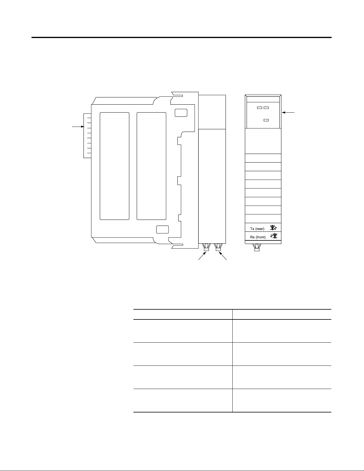
Physical Features of the ControlLogix SynchLink Module
Figure 1.1
Module side view Module front view
Backplane
Connector- Interface
to the ControlLogix
system backplane
Tr an sm it
Fiber Port
Receive
Fiber Port
LINK
COMM
LINK
SYNC
OK
Status
Indicators
42744
Publication 1756-UM521C-EN-P - July 2004
Table 1.4 lists descriptions of the physical features shown in Figure 1.1.
Table 1.4
Physical Feature: Description:
Backplane connector The backplane connector connects the
module to the ControlLogix chassis
backplane.
Status indicators The status indicators display the module’s
communications and SynchLink system
status.
Transmit fiber port The transmit fiber port allows connection
(via fiber optic cables) to other SynchLink
modules so the module can send data.
Receive fiber port The receive fiber port allows connection (via
fiber optic cables) to other SynchLink
modules so the module can receive data.
Page 19
What is the 1756-SYNCH module? 1-5
Using Module Identification and Status Information
Each ControlLogix SynchLink module maintains specific identification
information that separates it from all other modules. This information assists
you in tracking all the components of your system.
For example, you can track module identification information to be aware of
exactly what modules are located in any ControlLogix rack at any time. While
retrieving module identity, you can also retrieve the module’s status.
Each module maintains the following information:
Table 1.5 Module Identification and Status Information
Module Identification: Description:
Product Type Module’s product type, such as Digital I/O or Analog I/O
module
Product Code Module’s catalog number
Major Revision Module’s major revision number
Minor Revision Module’s minor revision number
Status Module’s status. Returns the following information:
• Controller ownership (if any)
• Whether module has been configured
• Device Specific Status, such as:
– Self-Test
– Flash update in progress
– Communications fault
– Not owned (outputs in program mode)
– Internal fault (need flash update)
– Run mode
• Minor recoverable fault
• Minor unrecoverable fault
• Major recoverable fault
• Major unrecoverable fault
Vendor ID Module manufacturer vendor, for example Allen-Bradley
Serial Number Module serial number
Length of ASCII Text String Number of characters in module’s text string
ASCII Text String Module name
IMPORTANT
To retrieve this information, you can use the WHO service
in RSLinx. For more information on how to retrieve
module identification information, see the RSLinx online
help.
Publication 1756-UM521C-EN-P - July 2004
Page 20
1-6 What is the 1756-SYNCH module?
Preventing Electrostatic Discharge
Removal and Insertion Under Power
This module is sensitive to electrostatic discharge.
ATTENTION
These modules are designed to be installed or removed while chassis power is
applied.
WARNING
This equipment is sensitive to electrostatic discharge, which
can cause internal damage and affect normal operation.
Follow these guidelines when you handle this equipment:
• Touch a grounded object to discharge potential static.
• Wear an approved grounding wriststrap.
• Do not touch connectors or pins on component
boards.
• Do not touch circuit components inside the equipment.
• If available, use a static-safe workstation.
• When not in use, store the equipment in appropriate
static-safe packaging.
When you insert or remove the module while backplane
power is on, an electrical arc can occur. This could cause an
explosion in hazardous location installations. Be sure that
power is removed or the area is nonhazardous before
proceeding.
Chapter Summary and What’s Next
Repeated electrical arcing causes excessive wear to contacts on both the
module and its mating connector. Worn contacts may create electrical
resistance that can affect module operation.
In this chapter, you read about the ControlLogix SynchLink module. For
information about Time Synchronization in the ControlLogix System, see
Chapter 2.
Publication 1756-UM521C-EN-P - July 2004
Page 21
Chapter
Time Synchronization in the
ControlLogix System
This chapter describes how the ControlLogix SynchLink module fits in
the ControlLogix system.
Table 2.1
For information on: See page:
Using the Coordinated System Time (CST) 2-2
Time Synchronization in a Distributed Control System 2-2
Time Synchronization in the SynchLink System 2-2
How Do the CST Clock and SynchLink Node Clock Work Together? 2-5
2
What are the SynchLink Configurations? 2-6
Before you can fully understand how the SynchLink module can be
used in a distributed ControlLogix system, you should understand
how a ControlLogix application works without SynchLink. See the
ControlLogix System User Manual, publication 1756-UM001 for a
detailed description of the ControlLogix system.
IMPORTANT
In RSLogix 5000, v13 or greater, you can use a
1756-SYNCH module in a remote chassis without a
ControlLogix controller and still provide a CST value
for the chassis. I/O modules (e.g., 1756-IH16ISOE)
can use the CST value when generating timestamps.
For SynchLink systems that use RSLogix 5000, v12 or
earlier, you cannot use a 1756-SYNCH module to
synchronize I/O timestamps in a remote chassis
without first installing a ControlLogix controller in
that chassis.
1 Publication 1756-UM521C-EN-P - July 2004
Page 22

2-2 Time Synchronization in the ControlLogix System
Using the Coordinated System Time (CST)
Time Synchronization in a Distributed Control System
The Coordinated System Time (CST) is the clocking mechanism used
to achieve time synchronization in a ControlLogix chassis. The
ControlLogix Coordinated System Time (CST) clock is a 64-bit clock
on the backplane of the ControlLogix chassis. It has a 1μS resolution
and is used as the main time reference for all modules plugged into a
chassis backplane.
For more information on how the ControlLogix CST affects the
operation of other ControlLogix products, see the ControlLogix System
User Manual, publication 1756-UM001.
The same CST mechanism described above is also used to
synchronize ControlLogix chassis in a distributed control system. In
such a system, SynchLink transfers the CST value from the CST Master
chassis to CST Slave chassis.
Each chassis must be equipped with a SynchLink module and,
depending on what version of RSLogix 5000 the system is using, each
chassis may or may not require that a controller reside in remote
chassis. This distributed control system is identified as a SynchLink
system.
Time Synchronization in the SynchLink System
The 1756-SYNCH module provides synchronization of CSTs between
ControlLogix chassis provides with no more than +/-5µs drift
between chassis.
Time synchronization within a SynchLink system is required to:
• transfer a CST value from the CST Master chassis to CST Slave
chassis.
• transfer motion and drive control data.
• support time synchronization between ControlLogix chassis and
non-ControlLogix products (e.g. PowerFlex 700S products).
The SynchLink Node Clock is integral to all devices that contain the
SynchLink circuitry. It is the clocking mechanism on the fiber optic
side of the SynchLink system. This clock has a resolution of 1μS.
During system configuration, you establish one SynchLink node clock
as the master system clock on the SynchLink fiber. By design, the
ControlLogix chassis that is configured as the SynchLink master also
acts as the CST master of the system. In this manner, one SynchLink
node acts as a Time Master for the entire system. This chapter gives
more detail on how this functionality is accomplished.
Publication 1756-UM521C-EN-P - July 2004
Page 23
Time Synchronization in the ControlLogix System 2-3
Multiple Rockwell Automation products can be synchronized with
SynchLink. In addition to the SynchLink module, the PowerFlex 700S
and the 1756-DMxxx series products (both used for drive control) also
use SynchLink to achieve drive to drive synchronization. While all of
these products maintain interoperability, not all SynchLink features are
incorporated into every product that uses SynchLink; the 1756-SYNCH
module, however, uses all of the SynchLink features.
SynchLink Node Clock
The SynchLink node clock is integral to the SynchLink circuit design.
Any product incorporating SynchLink incorporates the SynchLink
node clock as a base-line requirement. The SynchLink node clock has
a 1μS resolution and is synchronized from node to node when the
SynchLink system is configured.
SynchLink uses a Time Master-Slave mechanism to achieve time
synchronization. During system configuration, you configure one
SynchLink node as the Time Master and all other nodes as Time
Slaves. The SynchLink node that is configured as Time Master
becomes the system clock for the entire SynchLink system. As such,
the SynchLink Time Master broadcasts its time reference to the
SynchLink Time Slaves which adjust their node clocks to be in phase
with the master clock.
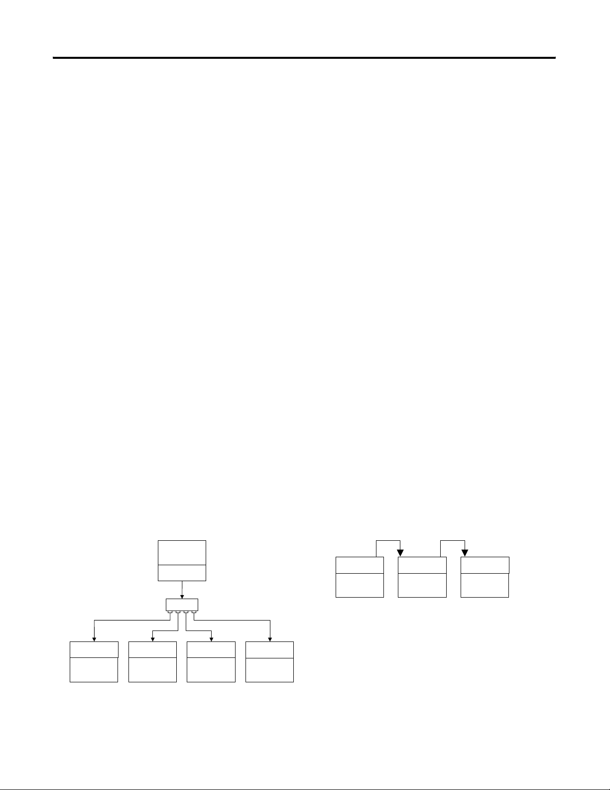
Because SynchLink is a unidirectional, broadcasting mechanism, the
master is always placed at the beginning of SynchLink systems using
the star or daisy chain configurations.
Figure 2.1
Star Configuration
SynchLink
Time Master
S.L.N.C.
Hub
S.L.N.C. S.L.N.C. S.L.N.C. S.L.N.C.
SynchLink
Time Slave
SynchLink
Time Slave
SynchLink
Time Slave
SynchLink
Time Slave
S.L.N.C. = SynchLink Node Clock
42980
Daisy Chain Configuration
S.L.N.C. S.L.N.C. S.L.N.C.
SynchLink
Time Master
SynchLink
Time Slave
SynchLink
Time Slave
42981
Publication 1756-UM521C-EN-P - July 2004
Page 24
2-4 Time Synchronization in the ControlLogix System
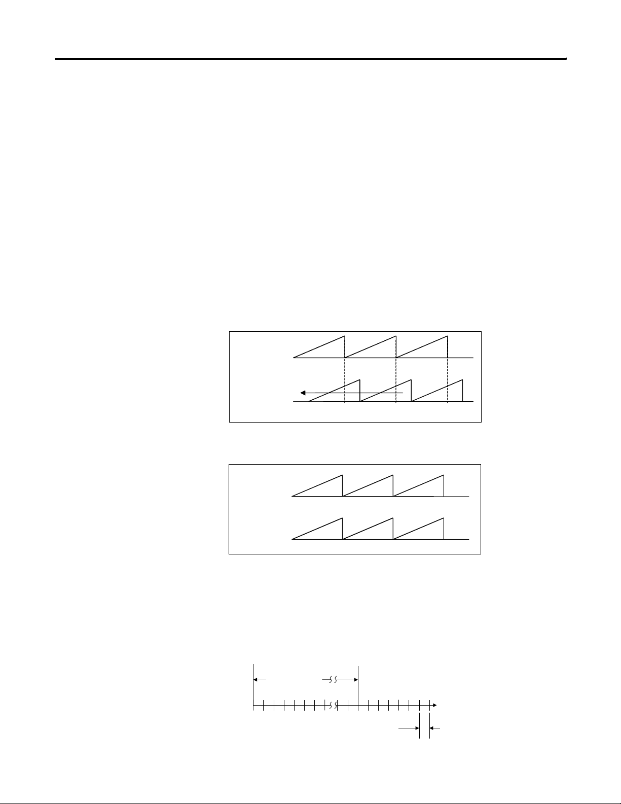
System Synchronization
When a SynchLink system is initialized, the individual SynchLink
nodes power-up at separate times and the individual SynchLink node
clocks begin to count at arbitrary points in time. When this occurs, the
system is not yet synchronized. As the master node clock counts, it
reaches a point where it rolls over and goes back to zero.
When the rollover occurs, the SynchLink Time Master transmits a
beacon signal to the SynchLink Time Slaves; the beacon is included in
the control field of the transmitted message. When the SynchLink
Time Slave receives the first message with the beacon signal, it begins
to adjust the 1μs time base of its node clock to synchronize with the
master clock. This process can be gradual or immediate, depending
on the product implementation.
Figure 2.2
Initial Start-Up
Master
Time adjustment
Slave
Beacon Beacon Beacon
Synchronized Operation
Master
Slave
42982
42983
After a SynchLink Time Slave is synchronized with the Time Master,
each SynchLink frame that is transmitted serves as a 50μS “tick” (or
mark) used for the periodic adjustment of its clock’s 1μS time base.
This process provides highly accurate results.
Figure 2.3
Publication 1756-UM521C-EN-P - July 2004
Beacon signal
synchronizes
SynchLink node
clocks
SynchLink 50 microsecond message frame
serves as a “tick” to keep clocks synchronized
42984
Page 25
Time Synchronization in the ControlLogix System 2-5
How Do the CST Clock and SynchLink Node Clock Work Together?
64-bit clock
As stated earlier, the ControlLogix Coordinated System Time clock
(CST) is a 64-bit clock on the ControlLogix backplane. It is used as the
main time reference for all modules plugged into a ControlLogix
chassis. The SynchLink node clock is used to establish the time
reference on the SynchLink fiber.
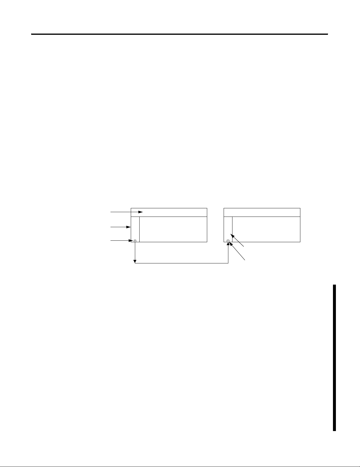
Figure 2.4 illustrates how the SynchLink node clock and the CST time
reference are coordinated in a system. In this example, the SynchLink modules
in chassis A & B synchronize the CST clock in chassis B with the CST
reference in chassis A.
Chassis A is the Time Master for the system. When the SynchLink
module strobes the beacon signal onto the fiber optic link, it also
transmits the CST time reference value that tells the downstream node
what time it is as the beacon occurs. The downstream chassis receives
the CST time reference and synchronizes its time with the CST
reference value on the beacon signal.
Figure 2.4
Chassis A Chassis B
Coordinated System Time Coordinated System Time
1756-SYNCH
SynchLink Node Clock
Configuring Time Mastership Functionality
1756-SYNCH
Clock
SynchLink beacon over the fiber optic link
You must configure each 1756-SYNCH module’s role in Coordinated
System Time (CST) Mastership. For any SynchLink system, there can
only be one SynchLink CST Time Master for the system; the Time
Master can be a 1756-SYNCH module or a ControlLogix controller. All
other devices connected to the SynchLink must be configured as Time
Slaves. However, the 1756-SYNCH modules that are Time Slaves are
Chassis CST Masters that receive the SynchLink time from the fiber
optic cable and relay it to all devices in their local chassis.
For example, the 1756-SYNCH modules in Figure 2.4 can be configured as
follows:
• 1756-SYNCH in Chassis A - MUST be SynchLink CST Master;
CAN also be Chassis CST Master
• 1756-SYNCH in Chassis B - MUST be Chassis CST Master;
CANNOT be SynchLink CST Master
For a full explanation on how to configure CST and SynchLink Mastership,
see page 3-18.
Publication 1756-UM521C-EN-P - July 2004
Page 26
2-6 Time Synchronization in the ControlLogix System
What are the SynchLink Configurations?
SynchLink communications are a unidirectional data transfer from one
SynchLink node to another. Each configuration starts with a single
Master Node. The SynchLink network can be configured in the
following ways.
• Star Configuration
• Daisy Chain Configuration
• Ring Configuration
Do not mix the configurations (i.e. begin in the star configuration and
change to the daisy chain configuration). Examples of these
configurations are shown in the following sections.
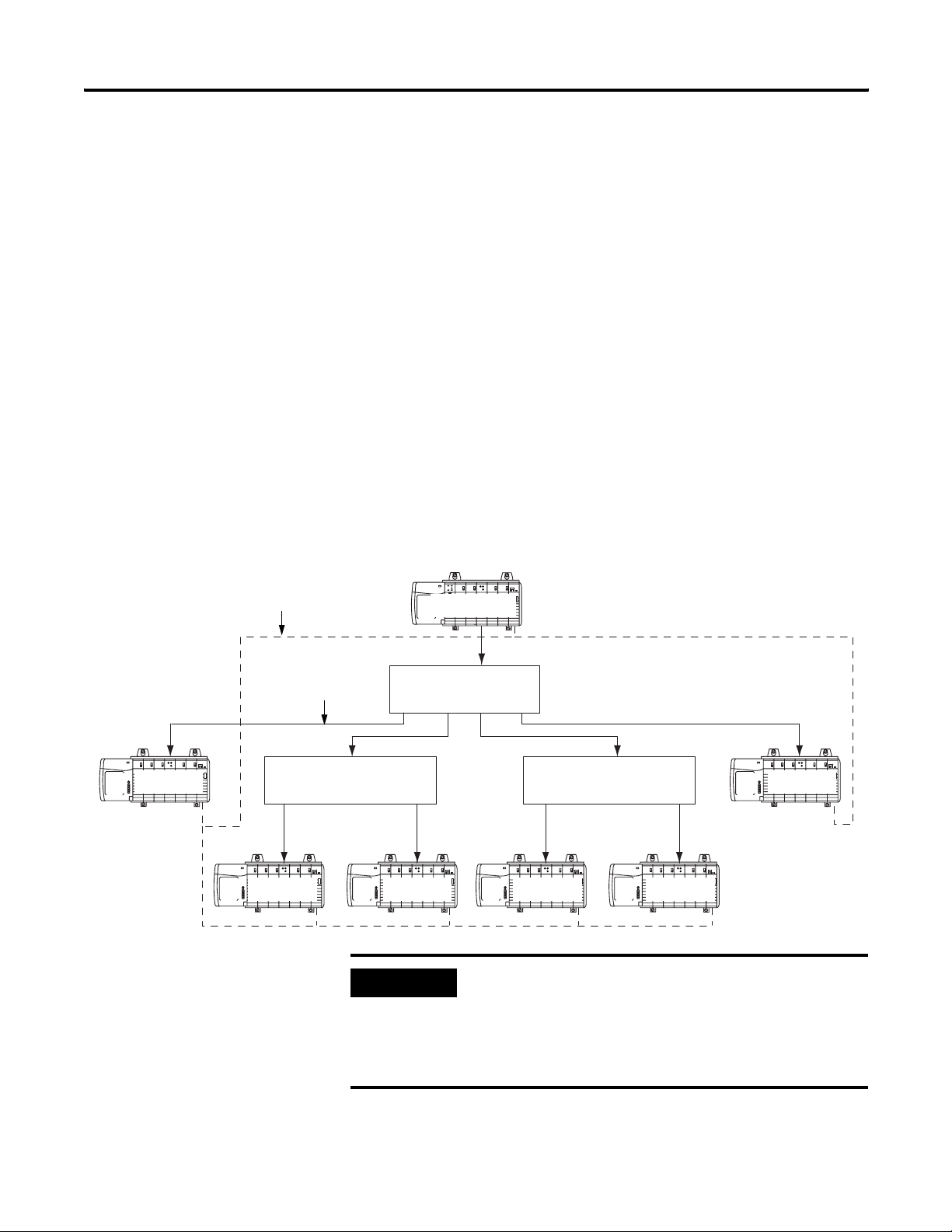
Star Configuration
The star configuration transfers data from a Master Node through
Hubs to End Nodes.
Figure 2.5
ControlNet
SynchLink
End Node End Node
End Node End NodeEnd NodeEnd Node
Hub Hub
IMPORTANT
Master Node
Hub
The star configuration supports 2 layers of hubs with
up to 16 end nodes connected to each hub.
A maximum of 257 SynchLink modules (including
the Master Node) can be connected in the star
configuration.
42747
Publication 1756-UM521C-EN-P - July 2004
For an example of how to configure a Star configuration, see Appendix B.
Page 27
Time Synchronization in the ControlLogix System 2-7
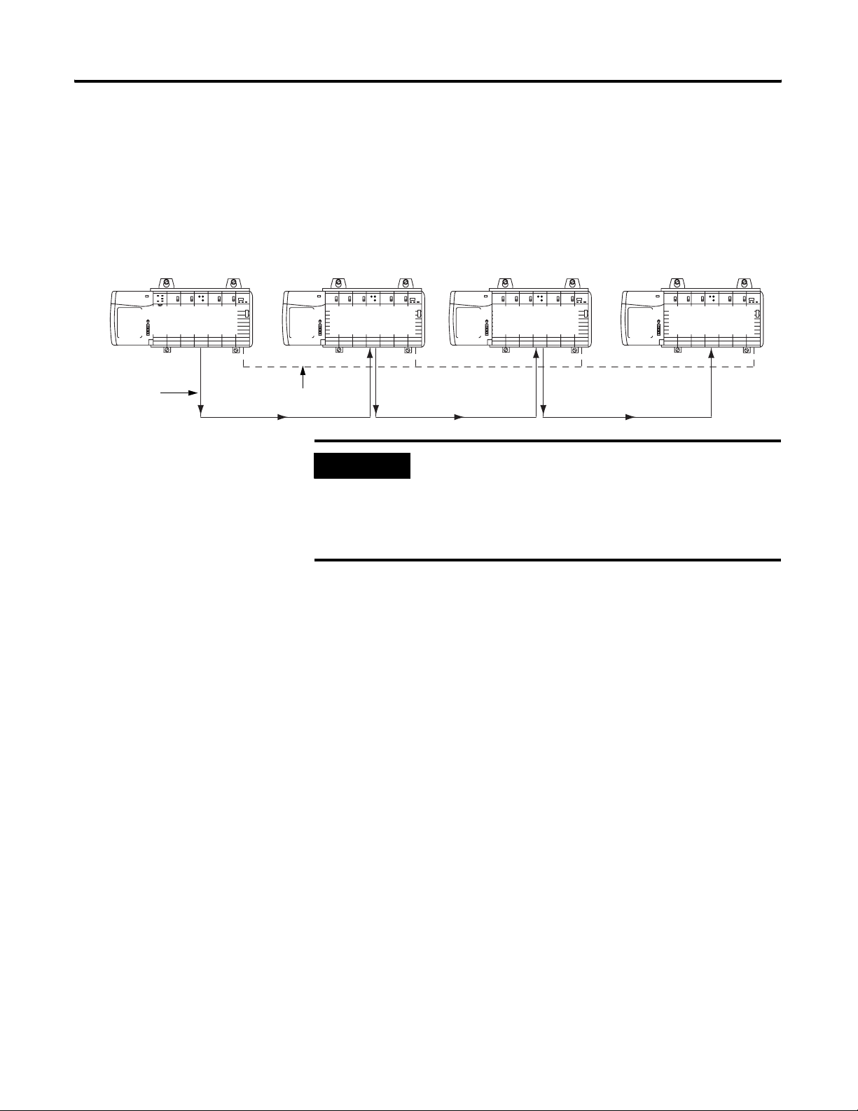
Daisy Chain Configuration
In the daisy chain configuration, the SynchLink network starts at the
Master Node and ends at an End Node. You can include Center Nodes
(shown in Figure ) in the configuration as needed.
Figure 2.6
Master Node Center Node Center Node End Node
ControlNetSynchLink
42746
IMPORTANT
In the daisy chain configuration, you can use a
maximum of 10 nodes, including the master and
end nodes.
Also, the only difference between Center and End
Nodes is their physical location.
In the daisy chain configuration the time synchronization process is
more complicated than in the star. It’s based on the following rules.
• Each node enables its transmitter right after it has received the
first message from the upstream node.
• Each node can generate and transmit the beacon signal
regardless of whether it has received one or not.
• Each node is a Time Slave of its upstream node and will attempt
to synchronize with it.
The SynchLink Time Master node must be set as the SynchLink Time
Master. Its node clock is the SynchLink system clock. After power-up,
the Master node begins to transmit a message every 50μS. As soon as
the node connected to it receives the first of these messages, it begins
to send messages to its downstream node. Eventually, all center nodes
are transmitting messages.
As soon as a node receives the first message with the beacon signal, it
starts to synchronize its node clock with the upstream node clock. The
node connected to the Master, is the first to synchronize its clock with
the SynchLink system clock. This process then propagates down the
daisy chain until all nodes are synchronized with the Master.
For an example of how to configure a Daisy Chain configuration, see
Appendix C.
Publication 1756-UM521C-EN-P - July 2004
Page 28
2-8 Time Synchronization in the ControlLogix System
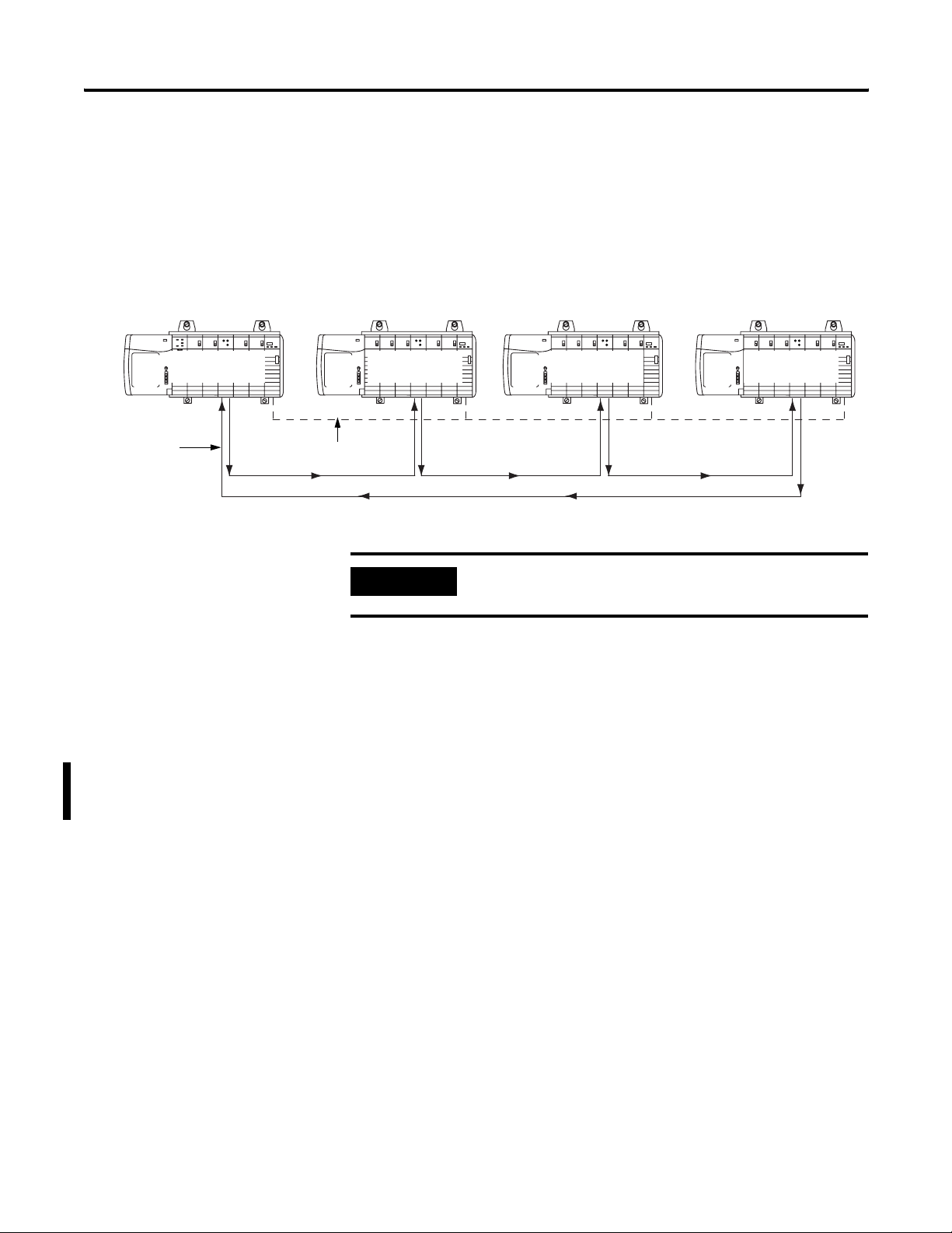
Ring Configuration
The ring configuration is a permutation of the daisy chain
configuration. In the ring chain configuration, the SynchLink network
starts and ends at the Master Node. You can include Center Nodes
(shown in Figure ) in the configuration as needed.
Master Node Center Node Center Node Center Node
ControlNetSynchLink
42748
Chapter Summary and What’s Next
IMPORTANT
For an example of how to configure a Ring configuration, see Appendix D.
In the ring chain configuration, you can use a
maximum of 10 nodes.
Cable Usage
You must use fiber optic cable to connect SynchLink modules in all
configurations. For more information on SynchLink fiber components,
see Table 1.2 and Table 1.3 on page 1-3.
For more information on choosing the correct cable lengths for your
application, see the SynchLink Design Guide, publication 1756-TD008.
In this chapter, you learned how the ControlLogix SynchLink module
fits into the ControlLogix system. For more information on SynchLink
Module Features, see Chapter 3.
Publication 1756-UM521C-EN-P - July 2004
Page 29
Chapter
SynchLink Module Features
This chapter describes the ControlLogix SynchLink module features.
Table 3.1
For information on: See page:
Module Features That Cannot Be Configured 3-2
Removal and Insertion Under Power (RIUP) 3-2
Module Fault Reporting 3-3
Full RSLogix 5000 Support 3-3
Status Indicator (LED) Information 3-4
Class I Division 2 Certification 3-4
Agency Certification 3-4
Use Last Configuration When Connection to Owner-Controller
Closes - For Module’s Using Firmware Revision 2.18 or Greater
Module Features That Can Be Configured 3-5
Communications Format 3-6
3-5
3
Electronic Keying 3-11
Requested Packet Interval 3-13
SynchLink Transmitted Axes 3-15
Transmitted Direct Words 3-16
CST and SynchLink Mastership 3-18
Configurable module features are features (e.g. Communications
Format) that can be configured to work differently in various
SynchLink applications.
1 Publication 1756-UM521C-EN-P - July 2004
Page 30

3-2 SynchLink Module Features
Module Features That Cannot Be Configured
These general module features (e.g. Removal and Insertion Under
Power) are supported on the module regardless of configuration and
application. The following general module features are available with
the ControlLogix SynchLink module:
• Removal and Insertion Under Power (RIUP)
• Module Fault Reporting
• Full RSLogix 5000 Support
• Status Indicator (LED) Information
• Class I Division 2 Certification
• Agency Certification
• Use Last Configuration When Connection to Owner-Controller Closes
- For Module’s Using Firmware Revision 2.18 or Greater
Removal and Insertion Under Power (RIUP)
All ControlLogix SynchLink modules may be removed and inserted
from the chassis while power is applied. This feature allows greater
availability of the overall control system because, while the module is
being removed or inserted, there is no additional disruption to the rest
of the controlled process.
Although there is no disruption to other devices when the SynchLink
module is removed and inserted from the chassis while power is
applied, the removal and insertion will break communications
between SynchLink modules and will impact the performance of the
SynchLink system.
Removing and reinserting the SynchLink module under power also
impacts overall system performance and operation because the
ControlLogix chassis are no longer synchronized. Depending on the
application, removing and reinserting the SynchLink module under
power may cause significant changes to an application, including the
possibility of a system E-Stop (emergency stop).
Because of its impact on other chassis, the removal of a SynchLink
module while under power may cause personal injury or property
damage.
WARNING
When you insert or remove the module while
backplane power is on, an electrical arc can occur.
This could cause an explosion in hazardous location
installations. Be sure that power is removed or the
area is nonhazardous before proceeding.
Publication 1756-UM521C-EN-P - July 2004
Page 31

SynchLink Module Features 3-3
Repeated electrical arcing causes excessive wear to contacts on both
the module and its mating connector. Worn contacts may create
electrical resistance that can affect module operation.
Module Fault Reporting
ControlLogix SynchLink modules provide both hardware and software
indication when a module fault has occurred. Each module’s LED fault
indicator and RSLogix 5000 will graphically display this fault and
include a fault message describing the nature of the fault.
This feature allows you to determine how your module has been
affected and what action should be taken to resume normal operation.
Full RSLogix 5000 Support
RSLogix 5000 uses a custom, easily understood interface to write
configuration. All module features are enabled or disabled through the
I/O configuration portion of the software.
You can also use the software to interrogate any module in the system
to retrieve
• serial number
• revision information
• catalog number
• vendor identification
• error/fault information
By eliminating such tasks as setting hardware switches and jumpers,
the software makes module configuration easier and more reliable.
Publication 1756-UM521C-EN-P - July 2004
Page 32

3-4 SynchLink Module Features
Status Indicator (LED) Information
The ControlLogix SynchLink module has status indicators (LED) on
the front of the module that allow you to check the module health
and operational status.
With the LED indicators, you can check:
• SynchLink and ControlLogix backplane status
• Module health status
For examples of LED indicators, see page 6-1.
Class I Division 2 Certification
The ControlLogix SynchLink module is certified for use in
nonhazardous locations as well as Class I, Division 2 hazardous
Locations containing gas groups A, B, C, and D. This equipment may
be used as a component of a control system which is certified to
operate in hazardous locations.
WARNING
When you insert or remove the module while
backplane power is on, an electrical arc can occur.
This could cause an explosion in hazardous location
installations. Be sure that power is removed or the
area is nonhazardous before proceeding.
Agency Certification
When the SynchLink module is marked appropriately, the following
agency certifications apply:
• UL Listed Industrial Control Equipment
• CSA Certified Process Control Equipment
• CSA Certified for Class I, Division 2 Hazardous Locations
Publication 1756-UM521C-EN-P - July 2004
Page 33

Table 3.2
SynchLink Module Features 3-5
Use Last Configuration When Connection to Owner-Controller
Closes - For Module’s Using Firmware Revision 2.18 or Greater
With firmware revision 2.18 or greater, the 1756-SYNCH module can
continue to operate, using its last configuration, when the module’s
connection to the owner-controller closes.
If the 1756-SYNCH module is used in
this scenario:
• The 1756-SYNCH module is located
in a chassis with two ControlLogix
controllers.
• The 1756-SYNCH module is the time
master for the local chassis.
• One of the ControlLogix controllers is
the 1756-SYNCH module’s
owner-controller.
• The other ControlLogix controller is
controlling motion based on the CST
set by the 1756-SYNCH module.
Module Features That Can Be Configured
and the owner-controller closes its
connection to the 1756-SYNCH module,
such as for one of the following reasons:
• The controller is downloading a new
project.
• The controller is saving its NVS.
• The controller is restoring its NVS.
• The controller is updating the module’s
firmware.
• The controller is removed from
the chassis.
The 1756-SYNCH behaves as follows:
The module continues to act as time
master for the local chassis, operating as
directed by its most recent configuration.
The 1756-SYNCH module’s behavior only
changes if the owner-controller reopens
the connection to the module and
reconfigures the module.
The following SynchLink module features are configurable via
RSLogix 5000:
• Communications Format
• Electronic Keying
• Requested Packet Interval
• SynchLink Transmitted Axes
• Transmitted Direct Words
• CST and SynchLink Mastership
Each of these features is described in this section, including
information on which RSLogix 5000 configuration screen should be
used to configure the feature. For an overview of the entire
configuration process, see Chapter 5, Configuring the SynchLink Module.
Communications Format
The communications format defines the connection between the
owner-controller and the module (i.e. determines what type of data is
Publication 1756-UM521C-EN-P - July 2004
Page 34

3-6 SynchLink Module Features
transferred between them). The SynchLink module can receive and
transmit data and, therefore, uses a Receive Port Communications
Format and Transmit Port Communications Format.
SynchLink messages are structured as six 32-bit words; the words are
divided into three types as described in Table 3.3:
Table 3.3
Word Type: Description:
Direct Data delivered in a single message. A SynchLink message can contain
a maximum of four direct data words; each word is 32 bits in length.
Direct data can be automatically forwarded to the next node in the
daisy chain and ring configurations.
Buffered Data that exceeds the four word limit of a direct data transfer.
Buffered data is appropriately segmented at the transmitting module
and reassembled at the receiving module. Buffered data cannot be
automatically forwarded to the next node in the daisy chain and ring
configurations.
Axis data Motion data used by the motion planner in the controller. The
1756-SYNCH module can consume an Axis tag from a controller and
pass it over SynchLink. A controller in another chassis can then
consume axis tags passed over SynchLink from the 1756-SYNCH
module in that chassis. This data is not automatically forwarded in
daisy chain or ring configurations.
The Communications Formats available on the 1756-SYNCH module
use various combinations of the words described in Table 3.3. The following
choices are available:
• 1 Axis, 3 Direct Words, 14 Buffered
• 2 Axis
• 2 Axis, 3 Direct Words
• 2 Direct Words, 18 Buffered
• 4 Direct Words, 18 Buffered
• 4 Direct Words, 8 Buffered
• No Receive Data - Available on the Receive Port only
• Listen Only, No Transmit Data - Available on the Transmit
Port only
• No Transmit Data - Available on the Transmit Port only
Publication 1756-UM521C-EN-P - July 2004
Page 35

SynchLink Module Features 3-7
Multiple Port Communications Formats in Single Module
You must set a communications format for receiving data (Receive Port
Communications Format) and transmitting data (Transmit Port
Communications Format) in each SynchLink module. The following
requirements apply to communication format choices:
• If a SynchLink module does not receive data (e.g. a SynchLink
Time Master in a star or daisy chain configuration), you must
choose the No Receive Data Receive Port communication format.
• If a SynchLink module does not transmit data (e.g. an end
node), you must choose the No Transmit Data Transmit Port
communications format.
• The receive communication format for any SynchLink module
that receives data must match the transmit communications
format of the upstream node in the system. For example, if the
Time Master SynchLink module uses a 2 Axis Transmit Port
communication format, the SynchLink module physically
connected to the Time Master must use a 2 Axis Receive Port
communications format.
• If a SynchLink module is used to provide CST signals to remote
I/O chassis, you can choose any communication format except
No Receive Data, Listen Only or No Transmit Data. CST signals
are used in the remote chassis to synchronize I/O timestamps. In
this case, the data words transmitted over SynchLink are
not used.
IMPORTANT
The receive and transmit on the same module do not
have to match.
Also, once the module is created, you cannot change
the communications format. You must delete and
recreate the module.
Publication 1756-UM521C-EN-P - July 2004
Page 36

3-8 SynchLink Module Features
Module-Defined Data Tags
When you create a module, RSLogix 5000 creates module-defined data
types and tags. These tags allow you to access the Configuration,
Input and Output Data of the module via the controller’s ladder logic.
The types of tags created vary, depending on which communications
format you choose when creating a module. There are three types
of tags:
• Configuration Data Tags
• Input Data Tags
• Output Data Tags
For a complete listing of all the module-defined data tags available on
your SynchLink module, see Appendix E.
Internal Scan on SynchLink Module
Every 500μS, the SynchLink module scans its internal hardware and
captures a “snapshot” of the data there. This data is then sent to the
local owner-controller at the Change of State (COS) instance,
independent of the requested packet interval (RPI) rate. But,
depending on the communications formats chosen during module
configuration, data types are transmitted between SynchLink nodes
(via the fiber optic cable) at various rates and may be transmitted
multiple times between the 500μS snapshots.
IMPORTANT
The transfer rate times listed in Table 3.4 and Table 3.5
only represent the rate at which data is passed between
SynchLink modules over the fiber optic cable.
Although the data is passed over the fiber optic cable
at various rates, according to the communications
format choices, the owner-controllers in each local
chassis only receive the data after the local
SynchLink module’s internal scan every 500μS.
Publication 1756-UM521C-EN-P - July 2004
Page 37

SynchLink Module Features 3-9
The SynchLink module updates its receive and transmit buffers once
every 500μS. Because direct data can be passed through from node to
node once every 50μS, up to 10 nodes can be updated with direct
data in a single 500μS SynchLink scan. Pass-through functionality only
applies to direct data in a daisy chain configuration, though; axis data
and buffered data cannot be passed through. Instead, these data types
require the intervention of the local controller to move data along. For
this reason, it is not recommended that a daisy chain configuration
be used when distributing axis data among multiple axis in a
distributed control system.
For more information on the available Receive Port and Transmit Port
communication formats, see Table 3.4.
Table 3.4 SynchLink Module Receive Communications Formats
Receive Port Communications Format
1 Axis, 3 Direct Words, 14 Buffered Axis Data - Updated every 500μS
2 Axis Axis Data - Updated every 250μS
2 Axis, 3 Direct Words Axis Data - Updated every 500μS
2 Direct Words, 18 Buffered Direct Data - Updated every 50μS
4 Direct Words, 18 Buffered Direct Data - Updated every 50μS
4 Direct Words, 8 Buffered Direct Data - Updated every 50μS
No Receive Data No data updated in this format
Transfer Rate (across the fiber optic
cable) for Each Data Type:
Direct Data - Updated every 50μS
Buffered Data - Updated every 500μS
Direct Data - Updated every 50μS
Buffered Data - Updated every 250μS
Buffered Data - Updated every 500μS
Buffered Data - Updated every 250μS
Publication 1756-UM521C-EN-P - July 2004
Page 38

3-10 SynchLink Module Features
Table 3.5 SynchLink Module Transmit Communications Formats
Transmit Port Communications Format
Transfer Rate (across the fiber optic
cable) for Each Data Type:
1 Axis, 3 Direct Words, 14 Buffered Axis Data - Updated every 500μS
Direct Data - Updated every 50μS
Buffered Data - Updated every 500μS
2 Axis Axis Data - Updated every 250μS
2 Axis, 3 Direct Words Axis Data - Updated every 500μS
Direct Data - Updated every 50μS
2 Direct Words, 18 Buffered Direct Data - Updated every 50μS
Buffered Data - Updated every 250μS
4 Direct Words, 18 Buffered Direct Data - Updated every 50μS
Buffered Data - Updated every 500μS
4 Direct Words, 8 Buffered Direct Data - Updated every 50μS
Buffered Data - Updated every 250μS
Listen Only, No Transmit Data No data updated in this format
No Transmit Data No data updated in this format
The Communications Format feature is configured on the following screen.
Communications Formats
Publication 1756-UM521C-EN-P - July 2004
Page 39

SynchLink Module Features 3-11
Electronic Keying
Instead of plastic mechanical backplane keys, electronic keying allows
the ControlLogix system to control what modules belong in the
various slots of a configured system.
During module configuration, you must choose one of the following
keying options for your 1756-SYNCH module:
• Exact Match
• Compatible Match
• Disable Keying
When the controller attempts to connect to and configure a
1756-SYNCH module (e.g. after program download), the module
compares the following parameters before allowing the connection
and configuration to be accepted:
• Vendor
• Product Type
• Catalog Number
• Major Revision - Change that affects the module’s function or
RSLogix 5000 interface
• Minor Revision - Change that does not affects the module’s
function or RSLogix 5000 interface (e.g. bug fixes)
The comparison is made between the keying information present in
the SynchLink module and the keying information in the controller’s
program. This feature can prevent the inadvertent operation of a
control system with the wrong module in the wrong slot. For
example, if you select Exact Match and a module with revision 2.10 is
placed in a location configured for a module with revision 2.18, the
controller does not make a connection to the new module because of
the mismatched revisions.
Publication 1756-UM521C-EN-P - July 2004
Page 40

3-12 SynchLink Module Features
Table 3.6 describes the keying options available with your 1756-SYNCH
module.
Table 3.6
Keying option: Definiton:
Exact Match All of the parameters listed above must match or the inserted module will reject a connection to the controller.
Compatible Match The Compatible Match mode allows a 1756-SYNCH module to determine whether it can emulate the module
defined in the configuration sent from the controller.
With 1756-SYNCH modules, the module can emulate older revisions. The module will accept the configuration
if the configuration’s major.minor revision is less than or equal to the physical module’s revision.
For example, if the configuration contains a major.minor revision of 2.10, the module inserted into the slot
must have a firmware revision of 2.10 or higher for a connection to be made. When a module is inserted with
a major.minor revision that is less than the revision for which the slot is configured (i.e. the module has a
revison of 1.17 and the slot is configured for a module with revision 2.18), no connection is made between the
controller and the I/O module.
TIP
We recommend using Compatible Match whenever possible. Remember, though, with
major revision changes, the module only works to the level of the configuration.
If a slot is configured for a module with major.minor revision of 1.17 and you insert a
module with a major.minor revision of 2.10, the module works at the 1.17 level, with
respect to module functions that are related to RSLogix 5000 such as interface changes.
However, bug fixes that are affected by the module’s firmware, would work at the 2.10
revision level.
If possible, we suggest you make sure configuration is updated to match the revision
levels of all I/O modules. Failure to do so may not prevent the application from working
but may defeat the purpose of upgrading your modules’ revision levels.
Disable Keying The inserted module attempts to accept a connection to the controller regardless of its type.
ATTENTION
If keying is disabled, a controller makes a connection with most modules of the same type as that used in the
slot configuration. Even if keying is disabled, a controller will not establish a connection if the slot is
configured for one module type (e.g. input module) and a module of another type (e.g. output module) is
inserted in the slot.
Be extremely cautious when using the disable keying option; if used incorrectly, this
option can lead to personal injury or death, property damage or economic loss.
Publication 1756-UM521C-EN-P - July 2004
Page 41

SynchLink Module Features 3-13
The Electronic Keying feature is configured on the following screen.
Electronic Keying
Requested Packet Interval
The Requested Packet Interval (RPI) is a configurable parameter that
defines when the module multicasts its data onto the local chassis
backplane. In the SynchLink module, though, the RPI’s role is dictated
by the data the SynchLink transfers.
Axis Data
The RPI does not have an effect on produced or consumed axis data.
In a distributed motion control application, the coarse planner update
establishes the timing of the axis data updates from the producing
controller to the consuming 1756-SYNCH module in the master
chassis. Likewise, in the slave chassis, the RPI parameter does not
affect the delivery of the axis data to the consuming processor. This
data is produced at the coarse update rate established in the master
chassis.
Publication 1756-UM521C-EN-P - July 2004
Page 42

3-14 SynchLink Module Features
Buffered, Direct and Diagnostic Data - RPI Effect on Input Data (to the
controller)
The RPI is one of two mechanisms available through the 1756-SYNCH
module to update the module’s input data onto the backplane. Input
data is transferred from the SynchLink module to its owner-controller
at the rate defined in the RPI.
In addition to the RPI, Change of State (COS) functionality also causes
the module to produce its data to the consuming controller whenever
the values of the data changes. The RPI timer is asynchronous to the
COS functionality. Both cause the module to produce data when
triggered.
Buffered, Direct and Diagnostic Data - RPI Effect on Output Data (from the
controller)
As a producing controller writes data to the 1756-SYNCH module, the
output data is placed in a local buffer until the next RPI reset occurs.
When the RPI timer expires, the output data is moved from the
controller’s local buffer to the 1756-SYNCH module.
Requested Packet Interval
The RPI timer is asynchronous to the program execution. Therefore, a
worst case update to the SynchLink module can be calculated by
adding the program execution time to the RPI timer setting, as
configured by the user.
The SynchLink module minimum RPI = 2.0mS. The RPI is configured
on the following screen:
Publication 1756-UM521C-EN-P - July 2004
Page 43

SynchLink Module Features 3-15
SynchLink Transmitted Axes
Most applications using the ControlLogix SynchLink module use it for
Remote Axis Control. You can use the SynchLink module to produce
axes from a master chassis and broadcast the data to other chassis.
The module can produce and consume two axes (i.e. Axis 0 & Axis 1).
Slave chassis consume the broadcast axis data and redistribute it to
their local motion planners (i.e. the Logix controller in their local
chassis). The controller in the slave chassis must be configured to
consume axis data from the local SynchLink module. With this
configuration, you can control multiple axes synchronously
throughout the system.
The SynchLink Transmitted Axes are configured on the following
screen:
Transmitted Axes
For an example configuration that uses Remote Axis Data, see Appendix B,
Configuring the Star Configuration.
IMPORTANT
This manual assumes you know how to set-up axis
data tags for the data the controller in the Time
Master chassis produces; this manual does not intend
to explain how to plan the motion portion of your
application as that is a controller function.
If you do not know how to set-up remote axis data
tags and account for them in the motion portion of
your application, see the ControlLogix Motion
Module Setup & Configuration User Manual,
publication 1756-UM006.
Publication 1756-UM521C-EN-P - July 2004
Page 44

3-16 SynchLink Module Features
Transmitted Direct Words
The SynchLink module can transmit data from the following direct
word sources:
• Output Direct Words (0-3)
• Received Direct Words (0-3)
• Multiplier
In initial configuration, you can choose the Transmitted Direct Words,
but you must use ladder logic to move data to those locations in data
type tags. For more information on the data tags, see Appendix E.
Direct Words
Direct words are data delivered in a single message. These can be
read from the module input tags (i.e. Local.x.I.DirectData[x]) and sent
from the module output tags (i.e. Local.x.O.DirectData[x]). A
SynchLink message can contain a maximum of four direct data words;
each word is 32 bits in length. Direct data can be automatically
forwarded to the next node in the daisy chain or ring configuration.
Multiplier
The Multiplier multiplies one Direct Word on the receive port by the
value in the local tag "Local:x:O.Multiplier" before transmitting it out
the transmit port. This is useful when your application requires fine
adjustments to the direct word between SynchLink nodes.
EXAMPLE
Although you can configure the multiplier for any of the Direct Words,
it can only be used with one Direct Word at a time.
If the Direct Word 0 passes process status on and the
local controller in the downstream chassis identifies
a change in the process, you can use the multiplier
to change the value of the direct word before
passing it on to the next processor.
Publication 1756-UM521C-EN-P - July 2004
Page 45

SynchLink Module Features 3-17
The multiplier can only transmit the same word it received (i.e. this
feature does not allow your module to receive direct word 0 and
transmit it as direct word 1). The multiplier output is limited to 16 bits;
any value generated by the multipler larger than 65535 is truncated to
16 bits, and a multiplier overflow error (described below) is reported
by the Synchlink module. Make sure any data that is passed onto the
Output word is less than 65535 else you receive incorrect output data.
IMPORTANT
The Multiplier on Transmitted Direct Words truncates
values after the decimal point and can give
misleading results under some circumstances. For
example, using a multiplier of 0.95 with a value of 20
yields a result of 18 instead of the expected 19. The
reason for this error is that 0.95 is represented by a
floating point value (~0.949999). The result of
18.9998 is truncated to 18 instead of rounded to 19.
We recommend you verify your results when using
the multiplier function.
Mutiplier Overflow
The Multiplier Overflow bit is a data tag (Local.x.I.SynchLinkMultiplier
Overflow) that exceeds the maximum multiplier value of 65535. This value is
reported back to you through the input data tags.
IMPORTANT
If you want to pass a Multiplier Overflow value
(received from an upstream node) to a third node
downstream but not locally change the direct word
data transmitted to the downstream node, you must
use a Multiplier value = 1.
Transmitted Direct Words
The Transmitted Direct Words are configured on the following screen:
Publication 1756-UM521C-EN-P - July 2004
Page 46

3-18 SynchLink Module Features
CST and SynchLink Mastership
The SynchLink module can be configured for multiple mastership and
slave roles in respect to the Coordinated System Time and the
SynchLink. Table 3.7 describes the ways you can configure your 1756-SYNCH
module’s role in CST Mastership.
Table 3.7 Possible SynchLink Configurations
This configuration: Means:
Only the Make SynchLink CST Master box is checked.
• This module relays time from the Chassis CST Master to the
SynchLink.
• The SynchLink node clock on this module is the SynchLink
Time Master.
• The chassis where the module resides is the CST Time
Master on SynchLink. Although the chassis establishes the
CST value for the SynchLink, the module is not CST master
of the chassis. In this case, another module (e.g. controller)
sets the CST value for the local chassis.
Both the Make SynchLink CST Master and Make Chassis CST
Master boxes are checked
Only the Make Chassis CST Master box is checked.
Dependence on SynchLink is Required • The module is a Time Slave on SynchLink.
This module is the System Time Master. It sets the CST for its local
chassis and all devices connected to the SynchLink.
In this case, you MUST configure the module for its dependence on
SynchLink. The module is a Time Slave on the SynchLink and
depends on the SynchLink fiber optic cable for CST mastership. The
1756-SYNCH module then relays the time from the cable to the
chassis in which it resides, acting as the Chassis CST master. The
1756-SYNCH module’s behavior varies in this configuration,
according to your configuration choices as described in the
following rows
• The module is the CST Time Master of the local chassis.
• You MUST have selected another module on the fiber optic
cable to be the SynchLink CST Master.
• If communications with the SynchLink CST Master are not
present when the 1756-SYNCH module powers up,
CST-dependent features will not start operating until the
communications to the SynchLink CST Master are restored.
• If communications with the SynchLink CST Master are
broken after operation has begun, the 1756-SYNCH module
stops relaying time to this chassis, and there will be no CST
signal in the chassis.
Publication 1756-UM521C-EN-P - July 2004
Page 47
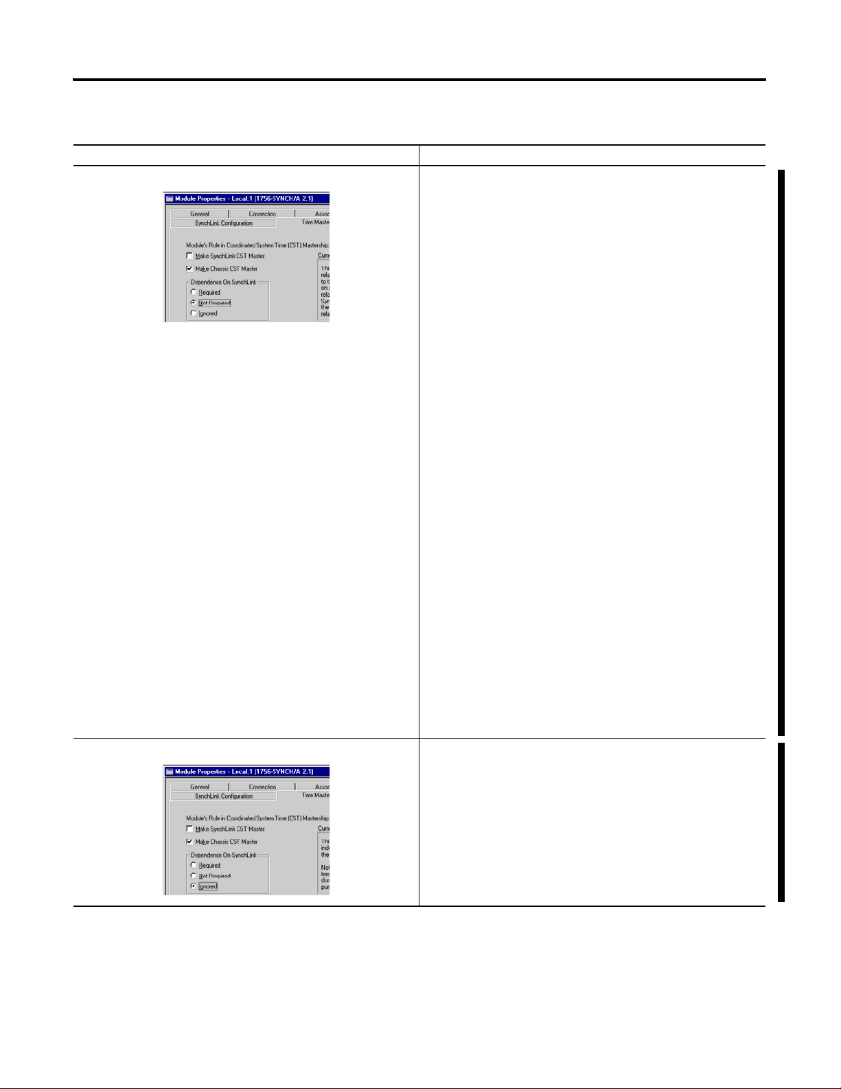
Table 3.7 Possible SynchLink Configurations
This configuration: Means:
Dependence on SynchLink is Not Required • The module is a Time Slave on SynchLink.
SynchLink Module Features 3-19
• The module is the CST Time Master of the local chassis.
• You MUST have selected another module on the fiber optic
cable to be the SynchLink CST Master.
• If your 1756-SYNCH module uses firmware revision 2.18
or greater and communications with the SynchLink CST
Master are not present at power-up, the module
automatically becomes the Time Master of its local chassis.
If a Time Slave 1756-SYNCH module becomes the Chassis
CST Master without the SynchLink CST master, then the
slave chassis is running unsynchronized motion.
Unsynchronized motion may be acceptable when
troubleshooting or performing machine maintenance. When
synchronized motion is required the application logic in the
slave chassis must check the proper status bit in the slave
1756-SYNCH module.
• If your 1756-SYNCH module uses firmware revision 2.10
or earlier and communications with the SynchLink CST
Master are not present at power-up, CST-dependent
features will not start operating until the communications to
the SynchLink CST Master are restored.
• If communications with the SynchLink CST Master are
broken after operation has begun, the module continues to
relay time and acts as Chassis CST Master. In this case, the
chassis is running unsynchronized motion that you must
account for in your application’s logic.
Dependence on SynchLink is Ignored
IMPORTANT: If your 1756-SYNCH is running unsynchronized
motion (i.e. because the connection to a SynchLink CST Master
either broke or never existed), when communications are resumed
with the Master over the fiber optic cable, you must do the
following to become synchronized with the CST Master:
• Stop all motion connected to this chassis.
• Reset the 1756-SYNCH module via application ladder logic
or RSLogix 5000.
• The module is a Time Slave on SynchLink.
• The module is the CST Time Master of the local chassis.
• You MUST have selected another module on the backplane
to be the SynchLink CST Master.
• The module acts as an unsynchronized Chassis CST Master.
In this case, the module ignores the SynchLink CST Master
at all times, including module power-up.
This option is expected to be a temporary mode of
operation.
For more information on configuring your SynchLink modules, see Chapter 5.
Publication 1756-UM521C-EN-P - July 2004
Page 48

3-20 SynchLink Module Features
Chapter Summary and What’s Next
In this chapter, you read about the ControlLogix SynchLink module
features. For information about Installing the SynchLink Module, see Chapter
4.
Publication 1756-UM521C-EN-P - July 2004
Page 49

Chapter
Installing the SynchLink Module
This chapter describes how to install the ControlLogix
SynchLink module.
Table 4.1
For information on: See page:
Noting the Power Requirements 4-1
Installing the Module 4-2
Connecting the Fiber Optic Cable 4-3
Removing the Module 4-4
4
Noting the Power Requirements
IMPORTANT
This module receives power from the 1756 chassis power supply and requires
2 sources of power from the backplane:
• 1200mA at 5.1V dc
• 3mA at 24V dc
Add this current/power value (6.19W) to the requirements of all other
modules in the chassis to prevent overloading the power supply.
Before you install and use your module you should have
already installed and grounded a 1756 chassis and power
supply.
To install these products, refer to the products’ user
documentation, as listed in Table Preface.3 on
page Preface-5.
1 Publication 1756-UM521C-EN-P - July 2004
Page 50

4-2 Installing the SynchLink Module
Installing the Module
You can install or remove the module while chassis power is applied.
WARNING
When you insert or remove the module while backplane
power is on, an electrical arc can occur. This could cause an
explosion in hazardous location installations.
Be sure that power is removed or the area is nonhazardous before proceeding.
Repeated electrical arcing causes excessive wear to contacts on both the
module and its mating connector. Worn contacts may create electrical
resistance that can affect module operation.
1. Align the circuit board with the top and bottom chassis guides.
Figure 4.1
Printed
Circuit
Board
20806-M
2. Slide the module into the chassis until the module locking tabs ‘click’.
Figure 4.2
Locking tab
Publication 1756-UM521C-EN-P - July 2004
20807-M
Page 51

Installing the SynchLink Module 4-3
Connecting the Fiber Optic Cable
Your 1756-SYNCH module has two ports for fiber optic cables. The front
port receives data, and the rear port transmits data.
1. Remove the plugs from the ports at the bottom of the module.
TIP
Keep the plugs that were removed to connect the fiber
optic cables. When the cables are disconnected, you can
reinsert the plugs to protect the ports.
2. Connect the fiber optic cables as shown below.
Figure 4.3
LINK
LINK
SYNC
COMM
OK
)
r
a
e
(r
x
T
(front)
Rx
31267
ATTENTION
Do not look directly into the fiber ports or fiber cables.
Light levels may cause damage to eyesight. The SynchLink
module is a Class 1 LED product.
Table 4.2 lists the possible connections that might be made to your
1756-SYNCH module and where to connect the fiber optic cable.
Table 4.2 Making Fiber Optic Cable Connections to the 1756-SYNCH Module
If your 1756-SYNCH
module is configured to:
transmit data only Connect the fiber optic cable to the rear port. The other end
receive data only Connect the fiber optic cable to the front port. The other end
transmit and receive data 1. Connect the fiber optic cable going to (i.e. transmitting
Make this fiber optic cable connection:
of the cable should be connected to a device receiving data
over the SynchLink from your 1756-SYNCH module.
of the cable should be connected to a device transmitting
data to your 1756-SYNCH module over the SynchLink.
the data to) a module receiving the data to the front port.
2. Connect the fiber optic cable coming from (i.e. receiving
the data from) a module transmitting data to the rear port.
This completes installation. Use the next section to remove your SynchLink
module if necessary.
Publication 1756-UM521C-EN-P - July 2004
Page 52

4-4 Installing the SynchLink Module
Removing the Module
ATTENTION
1. Pull the fiber optic cable out of the connection port.
Before you remove the module, you must disconnect the
fiber optic cables.
TIP
2. Push in the top and bottom locking tabs.
3. Pull the module out of the chassis as shown.
Figure 4.4
If you kept the plugs that were removed to connect the
fiber optic cables, reinsert them to protect the ports.
Locking tabs
20808-M
Chapter Summary and What’s Next
Publication 1756-UM521C-EN-P - July 2004
In this chapter, you read about how to install the ControlLogix SynchLink
module. For information about Configuring the SynchLink Module, see
Chapter 5.
Page 53

Chapter
5
Configuring the SynchLink Module
This chapter describes how to configure the ControlLogix SynchLink module
using RSLogix 5000.
Table 5.1
For information on: See page:
Overview of the Configuration Process 5-2
Choose a SynchLink Configuration 5-3
Creating a New Module 5-4
Downloading New Configuration Data 5-8
Changing Configuration After Module Operation Has Begun 5-9
RSLogix 5000 Configuration Software
You must configure your module upon installation. The module will not work
until it has been configured.
This chapter offers a configuration overview and the three available
ControlLogix SynchLink configurations. For specific examples of each
configuration, see the following:
• Star Configuration - Appendix B - This example shows a configuration
using Remote Axis Data.
• Daisy Chain Configuration - Appendix C
• Ring Configuration - Appendix D
Use RSLogix 5000 to write configuration for your SynchLink module. You
must write configuration for each module because module position in the
SynchLink system affects configuration. For example, if a SynchLink module is
the Time Master for the system, it must be configured as such.
1 Publication 1756-UM521C-EN-P - July 2004
Page 54

5-2 Configuring the SynchLink Module
Overview of the Configuration Process
Star Configuration Daisy Chain Configuration Ring Configuration
Steps 2 - 5 must be
taken for every
SynchLink module
(and its respective
chassis) in the
chosen SynchLink
configuration.
These configuration
changes occur
before module
operation begins.
Figure 5.1 shows an overview of the configuration process:
Figure 5.1
1. Choose a SynchLink configuration.
2. Create a new
RSLogix 5000
project.
3. Add a
SynchLink
module to
the RSLogix
5000 project.
4. Use the
wizard to
configure the
SynchLink
module.
Steps 6 - 7 should
only be taken as
necessary for each
module.
These configuration
changes occur after
module operation
has begun.
Publication 1756-UM521C-EN-P - July 2004
5. Download the RSLogix
program to the controller.
6. Change configuration (via
RSLogix 5000) as necessary.
7. Send new configuration (via
RSLogix 5000) to the module.
42986
Page 55

Configuring the SynchLink Module 5-3
Choose a SynchLink Configuration
42747
You must use one of the following SynchLink configurations:
Star Configuration - See Appendix B for an example.
Figure 5.2
ControlNet
SynchLink
Hub
Hub Hub
Daisy Chain Configuration - See Appendix for an example.
Figure 5.3
ControlNetSynchLink
42746
Ring Configuration - See Appendix D for an example.
Figure 5.4
ControlNetSynchLink
Publication 1756-UM521C-EN-P - July 2004
42748
Page 56

5-4 Configuring the SynchLink Module
Creating a New Module
A. Click on the triangle to see
the pull-down menu.
B. Click on Go Offline.
After you have started RSLogix 5000 and created a processor, you must create
a new module. The wizard allows you to create a new module and configure it.
IMPORTANT
You must be offline when you create a new module.
1. If your application is online, go offline.
2. Access the Select Module Type screen.
A. Right-click on I/O
Configuration.
B. Select New Module.
Publication 1756-UM521C-EN-P - July 2004
Page 57

A. Select a module.
Configuring the SynchLink Module 5-5
3. Select the module type.
B. Make sure the
Major Revision
number
matches the
label on the
side of your
module
C. Select a module.
4. Begin configuration on the naming screen.
A. Name the module.
B. Type a description (optional).
C. Choose a Communications
Format for the receive and
transmit ports. A detailed
explanation of this field is
provided on page 3-6.
D. Make sure the Minor Revision
number matches the label on
the side of your module.
E. Set your
module’s slot.
F. Choose an Electronic
Keying method. A
detailed explanation
of this field is
provided on the next
page 3-11.
G. When you are finished
on this page, click here.
Publication 1756-UM521C-EN-P - July 2004
Page 58

5-6 Configuring the SynchLink Module
Adjust the Requested Packet Interval
Inhibit the connection to the module
If you want a Major Fault on the Controller to
occur if there is connection failure with the
I/O module while in Run Mode, click here
This Fault box is empty when you are offline.
If a fault occurs while the module is online,
the type of fault will be displayed here. The
fault is a connection fault explaining why a
connection did not open.
5. When you click on Next, you see the series of wizard screens that enable
you to configure the module.
Although each screen maintains importance during online monitoring,
some of the screens that appear during this initial module configuration
process are blank. They are not shown here.
Click here to move to the next page
Use the pull-down menu, to choose
which axis data tags to transmit
over each axis.
Click here to move to the next page
Publication 1756-UM521C-EN-P - July 2004
Page 59

Use the pull-down menus to choose
which direct words are transmitted.
Configuring the SynchLink Module 5-7
Click here to move to the next page
Set the 1756-SYNCH module’s
role in Coordinated System
Time (CST) Mastership.
For more information on Time
Mastership, see CST and
SynchLink Mastership on
page 3-18.
Click here to finish configuration.
Publication 1756-UM521C-EN-P - July 2004
Page 60

5-8 Configuring the SynchLink Module
Downloading New Configuration Data
Pull down this menu and click
here to download the new data
After you have changed the configuration data for a module, the change does
not actually take affect until you download the new program which contains
that information. This downloads the entire program to the controller
overwriting any existing programs.
RSLogix 5000 verifies the download process with this pop-up screen.
Click here to download new data
This completes the download process.
Publication 1756-UM521C-EN-P - July 2004
Page 61

Configuring the SynchLink Module 5-9
Changing Configuration After Module Operation Has Begun
A. Click on the triangle to see
the pull-down menu.
B. Click on Go Offline.
You change configuration for your SynchLink module after operation has
begun, but you must go offline first. Follow these steps to change the
SynchLink module configuration:
1. Go offline.
2. Access the module properties in RSLogix 5000.
A. Right-click on the module
to see the pull-down menu.
B. Click on Properties.
Publication 1756-UM521C-EN-P - July 2004
Page 62

5-10 Configuring the SynchLink Module
A. In this example, the
Connection tab was
accessed to change the RPI.
B. Click on OK to make
the changes..
3. Make the necessary changes.
After you make your configuration changes, you must download the
new configuration, as described on page 5-8.
Chapter Summary and What’s Next
In this chapter, you read about the general configuration
process. For specific configuration examples, see:
• Appendix B - Star Configuration with Remote Axis Data
• Appendix C - Daisy Chain Configuration
• Appendix D - Ring Configuration
For information on Troubleshooting the SynchLink Module, see Chapter 6.
Publication 1756-UM521C-EN-P - July 2004
Page 63

Chapter
Troubleshooting the SynchLink Module
This chapter describes how to troubleshoot the ControlLogix SynchLink
module.
Table 6.1
For information on: See page:
Using the Status Indicators 6-1
Using RSLogix 5000 to Troubleshoot the Module 6-3
6
Using the Status Indicators
The SynchLink module uses status indicators to show SynchLink and
communications status (red/green) and a bi-colored LED for module "OK"
(red/green).
SynchLink
LINK
COMM
During power up, an indicator test is done and the following occurs:
• The "OK" indicator turns red for 1 second and then turns to flashing
green if it has passed the self-test.
LINK
SYNC
OK
42875
1 Publication 1756-UM521C-EN-P - July 2004
Page 64

6-2 Troubleshooting the SynchLink Module
Use Table 6.2 to troubleshoot your module.
Table 6.2
LED indicators: This display: Means: Take this action:
COMM Steady green light The module is configured and operating
properly.
COMM Off 1. The module is not powered
2. The module is not configured.
3. The module is configured to
receive data from SynchLink but
did not receive it in the last scan.
4. The module is configured to
transmit on SynchLink but has not
enabled its transmitter.
5. The Transmit and Receive
communications formats do not
match between linked modules.
SYNC Steady green light The module is the time master or a time
relay and synchronization is complete.
SYNC Flashing green light The module is configured:
• to be a time relay from SynchLink
to chassis backplane.
• with the Dependence on SynchLink
feature set to Not Required or
Ignored.
but has not synchronized with the
upstream device.
SYNC Flashing red light 1. The module is configured as the
CST time master and has detected
another CST time master.
None
1. Power the module.
2. Configure the module.
3. Check fiber connections and
diagnostic counter for errors. If the
problem persists, replace the
module.
4. Make sure configuration is
complete and downloaded. If the
problem persists, replace the
module.
5. In RSLogix 5000, make sure
communications formats match
between linked modules.
None
Check configuration and make sure all
modules in the system are online.
1. Check configuration throughout the
system and verify there is only one
CST time master.
Publication 1756-UM521C-EN-P - July 2004
2. The configuration information
received from SynchLink does not
match the module’s configuration.
3. The module is configured as time
master on SynchLink and has
received time information from
another time master on SynchLink.
2. Check configuration of this module
and all upstream SynchLink
devices.
3. Check configuration for all modules
in the system to make sure only
one is the SynchLink time master.
Page 65

Troubleshooting the SynchLink Module 6-3
Table 6.2
LED indicators: This display: Means: Take this action:
SYNC Off 1. The module is not powered.
1. Power the module.
2. The module is not configured as
time master or time relay.
3. The module is configured as a time
relay from chassis backplane to
SynchLink but is not synchronized
with a CST master on the
backplane.
4. The module is configured:
• to be a time relay from
SynchLink to chassis
backplane.
• with the Dependence on
SynchLink feature set to
Required.
but has not synchronized with the
upstream device.
OK Steady green light The module is operating properly. None
OK Flashing green light The module is powered and ready for
operation but has not received
configuration.
OK Steady red light The module has experienced an
unrecoverable error.
OK Flashing red light A flash upgrade is in process. Wait for upgrade to finish. New code may
2. \Configure the module for its
proper function.
3. Establish a CST master on the
backplane.
4. Check configuration and make sure
all modules in the system are
online.
Configure the module.
Replace the module.
be needed.
OK Off The module is not powered. Power the module, if needed.
Using RSLogix 5000 to
In addition to the LED display on the module, RSLogix 5000 alerts you to
fault conditions. You are alerted in the following ways:
Troubleshoot the Module
• Warning signal on the main screen next to the module-This occurs when
the connection to the module is broken
• Notification in the Tag Editor - General module faults are also reported
in the Tag Editor.
• Status on the Module Info Page
Publication 1756-UM521C-EN-P - July 2004
Page 66

6-4 Troubleshooting the SynchLink Module
The screens below display fault notification in RSLogix 5000.
Warning signal on main screen
Warning icon when a
communications fault occurs
or if the module is inhibited
Status section lists Major and
Minor Faults and the Internal
State of the module
Status line provides information on
the connection to the module
Warning signal - The module in slot 1 has a communications fault
Fault message in status line
Allen-Bradley
Specialty I /O
1756-SYNCH
1.1
FFFFFFFF
1756-SYNCH Ver. 1.0
Ok
Yes
Faulted
Notification in Tag Editor
!
!
Refresh Reset Module
None
None
Unconnected
Yes
No
Match
A value of 1 shows a fault for this
input point.
IMPORTANT: If all input fault bits are
set to 1, the controller cannot connect
to the module. In this case, the use the
Connection tab in the RSLogix 5000
properties wizard (see page 6-5) to
determine the problem. Also, the
RSLogix 5000 online help offers a
definition of all fault bits.
Publication 1756-UM521C-EN-P - July 2004
Page 67

The fault type is listed here
In this example, Error
16#0011 means Counter 0
was set to an invalid Opera-
Troubleshooting the SynchLink Module 6-5
Determining Fault Type
When you are monitoring a module’s configuration properties in
RSLogix 5000 and receive a Communications fault message, the Connection
page lists the type of fault.
For a detailed listing of the possible faults, their causes and suggested
solutions, see Module Table Faults in the online help.
Publication 1756-UM521C-EN-P - July 2004
Page 68

6-6 Troubleshooting the SynchLink Module
Using Diagnostic Counters
The 1756-SYNCH module uses diagnostic counters; the counters contain
additional information about the module. See Table 6.3 for more information
on the SynchLink module diagnostic counters. This information must be used
in the Destination field of the Configuration pop-up screen (page 6-10).
For more information on how to access the diagnostic counter information,
see page 6-7.
Table 6.3 SynchLink Module Diagnostic Counters
Name: Description: Data Type Attribute ID: Possible Values:
Status Status of this device on the
SynchLink system
DINT 1
This counter lists the status of the following bits (0 = bit is
not faulted, 1 = bit is faulted):
• Bit 0 - Reserved (default =0)
• Bit 1 - Reserved (default =0)
• Bit 2 - Receive fault. No data has been received
from the upstream device.
• Bit 3 - Data Fault. The upstream device is in the
idle state.
• Bit 4 - Data Comm Format Mismatch Fault. The
communications format of data received from the
upstream device does not match this device’s
receive port communications format.
• Bit 5 – Duplicate SynchLink Time Master Fault –
This device is configured to be SynchLink Time
Master but has received a CST update from
another Time Master
• Bit 6 – CST Drifting – CST synchronization with
SynchLink was not verified at last beacon but
was verified within last 6 beacon updates
• Bit 7 – CST Synchronization Fault – The device
CST is not synchronized with SynchLink.
• Bit 8 – Multiplier Overflow Fault – The output of
the multiplier exceeded 16 bits
• Bit 9 – Axis 0 Receive Fault – The device is
configured to receive Axis 0, but Axis 0 was not
received from the SynchLink system.
• Bit 10 – Axis 1 Receive Fault – The device is
configured to receive Axis 1, but Axis 1 was not
received from the SynchLink system.
• Bit 11 – Axis 0 Unclaimed Fault – Axis 0 was
received from the SynchLink system but was not
consumed by the local controller.
• Bit 12 - Axis 1 Unclaimed Fault – Axis 1 was
received from the SynchLink system but was not
consumed by the local controller.
• Bit 13 – Axis 0 Transmit Fault – The device is
configured to transmit Axis 0, but Axis 0 was not
produced by the local controller.
• Bit 14 – Axis 1 Transmit Fault – The device is
configured to transmit Axis 1, but Axis 1 was not
produced by the local controller.
• Bit 15 – SynchLink Revision Fault – The
SynchLink revision was received but the data is
not compatible with the receiving module’s
revision.
• Bits 16 to 31 – Unused (Default = 0)
Publication 1756-UM521C-EN-P - July 2004
Page 69

Troubleshooting the SynchLink Module 6-7
Table 6.3 SynchLink Module Diagnostic Counters
Name: Description: Data Type Attribute ID: Possible Values:
CRC Error
Counter
Number of CRC errors detected
on the SynchLink system since
DINT 2
0 to 2
32
- 1
power-up or last reset service
Framing Error
Counter
Number of framing errors
detected on SynchLink since
DINT 3
0 to 2
32
- 1
powerup or last reset service
Incomplete
Package Error
Counter
Number of incomplete package
errors detected on SynchLink
since powerup or last reset
DINT 4
0 to 2
32
- 1
service
SynchLink
Revision
Revision of SynchLink supported DINT 5 Bits 0 to 15 - Minor Revision
Bits 16 to 31 - Major Revision
Message Instructions
To retrieve and reset the SynchLink diagnostic counter information, you must
use a message instruction in ladder logic and a CIP message. This ladder logic
is written in the Main Routine section of RSLogix 5000.
Double-click to enter the
Main Routine
After adding a message
instruction to a rung, you must
create a tag for the message
instruction
1. Right-click on the
question mark (?) to see
this pull-down menu.
2. Click here to Create a
New Tag.
Publication 1756-UM521C-EN-P - July 2004
Page 70

6-8 Troubleshooting the SynchLink Module
Fill in the following information when the New Tag pop-up screen appears:
Name the tag here.
Enter an optional description here.
Choose the Base Tag Type here.
Choose the Message Data Type here.
Choose the Controller Scope here.
IMPORTANT: Message tags can only
be created with the Controller Scope.
IMPORTANT
We suggest you name the tag to indicate what module
service the message instruction is sending. For example, the
message instruction below is used to retrieve diagnostic
counters, and the tag is named to reflect this.
Publication 1756-UM521C-EN-P - July 2004
Page 71

Click here to see the message
configuration pop-up screens
Troubleshooting the SynchLink Module 6-9
Enter Message Configuration
After creating a new tag, you must enter message configuration.
Enter message configuration on the following screens:
• Configuration Pop-Up Screen
• Communication Pop-Up Screen
A description of the purpose and set-up of each screen follows.
IMPORTANT
In RSLogix 5000, version 10 and greater, the message
configuration screens changed significantly to make it
easier for you to configure you messages.
For example, in version 9 and earlier, depending on the
Message Type, you are required to configure some
combination of the following:
• Service Code
• Object Type
• Object ID
• Object Attribute
• Source
• Number of Elements
• Destination
In version 10 and greater, however, you are only required
to choose a Service Type. RSLogix 5000 fills in most of the
fields listed above. You are only required to configure the
Instance field; Instance represents the module channel on
which the service is performed, if appropriate
The following sections show how to configure messages
with RSLogix 5000, versions 9 and earlier and RSLogix
5000, versions 10 and greater.
Publication 1756-UM521C-EN-P - July 2004
Page 72

6-10 Troubleshooting the SynchLink Module
Message Type is CIP Generic
Service Code is 1
Class Name is 31B
Instance Name is 1
Attribute name is 0
Configuration Pop-Up Screen
This pop-up screen provides information on what module service to perform
and where to perform it. For example, you must use this screen to retrieve
diagnostic counters (module service) from the 1756-SYNCH module (where
to perform service).
There is no Source.
Number of Elements is 0
Destination is a tag of
type DINT [5].
IMPORTANT: The
data containted in
this DINT is described
in Table 6.3.
The configuration portion of a message instruction requires specific
information in the fields shown above to ensure that the correct service is
performed at the module. In the case of the 1756-SYNCH module, the most
common use for a message instruction is to use diagnostic counters to
recognize a problem on the module so you may correct it.
After correcting the problem, you probably will want to reset the counters for
future use. Table 6.4 shows the values necessary on the configuration pop-up
screen to retrieve counter and to reset counters.
Table 6.4 Configuration Pop-Up Screen Values Required to Reset SynchLink
Module Diagnostic Counters
Field: Value to Retrieve the Counter: Value to Reset the Counter:
Message Type CIP Generic CIP Generic
Service Code 1 5
Class 31B 31B
Instance 1 1
Attribute 0 0
Source NA NA
Source Length 0 0
Destination Retrieve Diagnostic Counters NA
Publication 1756-UM521C-EN-P - July 2004
Page 73

Troubleshooting the SynchLink Module 6-11
Communication Pop-Up Screen
This pop-up screen provides information on the path of the message
instruction. For example, the slot number of a 1756-SYNCH module
distinguishes exactly which module a message is designated for.
Use this
Browse button
to see a list.
IMPORTANT
Use the Browse button to see a list of the I/O modules in
the system. You choose a path when you choose a module
from the list.
RSLogix 5000, version 9 and earlier
RSLogix 5000, version 10 and greater
Publication 1756-UM521C-EN-P - July 2004
Page 74

6-12 Troubleshooting the SynchLink Module
Chapter Summary and What’s Next
In this chapter, you read how to troubleshoot the ControlLogix SynchLink
module. For information on the module specifications, see Appendix A.
Publication 1756-UM521C-EN-P - July 2004
Page 75

Specifications
General Specifications
Module Location 1756 ControlLogix chassis
Backplane Current 1200mA @ 5.1V dc & 3mA @ 24V dc
Maximum Power Dissipation 6.19W
Thermal Dissipation 21.1 BTU/hr
Connecting Cable
Fiber Type
Fiber Termination Type
Assemblies
Maximum Length
Minimum Length
Operating Wavelength 650nm (red)
200/230 micron Hard Clad Silica (HCS),
Versalink V-System
Order from Rockwell Automation under catalog number
1403-CFxxx or use the Lucent Technologies
HCP-M0200T V01RK 200μm simplex cable
300m
1m
Appendix
A
SynchLink Data Rate 5Mbps
Baud Rate 5Mbaud
Type of Communication Synchronous
Frame Period 50μs
Indicators Green and red indicators for operation, status and
diagnostics
Frame Parameters 3 Flags - 3 bytes
Control field - 1 byte
Data field - 24 bytes
CRC field - 2 bytes
Environmental Conditions
Operational Temperature IEC 60068-2-1 (Test Ad, Operating Cold),
IEC 60068-2-2 (Test Bd, Operating Dry Heat),
IEC 60068-2-14 (Test Nb, Operating Thermal Shock):
0 to 60°C (32 to 140°F)
Storage Temperature IEC 60068-2-1 (Test Ab, Un-packaged Non-operating
Cold),
IEC 60068-2-2 (Test Bb, Un-packaged Non-operating
Dry Heat),
IEC 60068-2-14 (Test Na, Un-packaged Non-operating
Thermal Shock):
-40 to 85°C (-40 to 185°F)
Relative Humidity IEC 60068-2-30 (Test Db, Un-packaged Non-operating
Damp Heat):
5 to 95% non-condensing
1 Publication 1756-UM521C-EN-P - July 2004
Page 76

A-2 Specifications
Vibration IEC 60068-2-6 (Test Fc, Operating):
2g @ 10-500Hz
Operating Shock IEC 60068-2-27 (Test Ea, Unpackaged Shock):
30g
Non-operating Shock IEC 60068-2-27 (Test Ea, Unpackaged Shock):
50g
Emissions CISPR 11:
Group 1, Class A
ESD Immunity IEC 61000-4-2:
6kV contact discharges
8kV air discharges
Radiated RF Immunity IEC 61000-4-3:
10V/m with 1kHz sine-wave 80%AM from 30MHz to
1000MHz
10V/m with 200Hz 50% Pulse 100%AM at 900Mhz
EFT/B Immunity IEC 61000-4-4:
±4kV at 2.5kHz on power ports
Conducted RF Immunity IEC 61000-4-6:
10Vrms with 1kHz sine-wave 80%AM from 150kHz to
80MHz
Enclosure Type Rating None (open-style)
Certifications:
(when product is marked)
UL UL Listed Industrial Control Equipment
CSA CSA Certified Process Control Equipment
CSA CSA Certified Process Control Equipment for
Class I, Division 2 Group A,B,C,D Hazardous
Locations
(1)
CE
European Union 89/336/EEC EMC Directive,
compliant with:
EN 50082-2; Industrial Immunity
EN 61326; Meas./Control/Lab., Industrial
Requirements
EN 61000-6-2; Industrial Immunity
EN 61000-6-4; Industrial Emissions
(1)
C-Tick
Australian Radiocommunications Act,
compliant with:
AS/NZS CISPR 11; Industrial Emissions
(1)
See the Product Certification link at www.ab.com for Declarations of Conformity, Certificates, and other certification details.
Publication 1756-UM521C-EN-P - July 2004
Page 77

Appendix
Configuring the Star Configuration
This appendix describes how to configure the ControlLogix SynchLink
module in a Star configuration using remote axis control. In this example
configuration, the following occurs:
• The controller in the Time Master chassis produces axis data.
• The axis data is transmitted via SynchLink modules to each Time Slave
chassis.
• The controller in each Time Slave chassis consumes the axis data.
The system’s physical configuration is shown in Figure B.1. In this
configuration, you must:
B
• configure the Master Node in an RSLogix 5000 project.
• configure each End Node in separate RSLogix 5000 projects.
Figure B.1
The SynchLink module in
ControlNet
SynchLink
End Node
The SynchLink modules in these chassis are configured as
the CST Time Masters and SynchLink Time Slaves.
Master Node
Hub
End Node
this chassis is configured
as the Time Master for
the SynchLink.
42882
1 Publication 1756-UM521C-EN-P - July 2004
Page 78

B-2 Configuring the Star Configuration
Using Remote Axis Control
Time Master Chassis
Most applications using the ControlLogix SynchLink module use it for
Remote Axis Control. You can use the SynchLink module to produce axes
from a master chassis and broadcast the data to other chassis.
Slave chassis consume the broadcast axis data and redistribute it to their local
motion planners (i.e. the Logix controller in their local chassis). With this
configuration, you can control multiple axes synchronously throughout the
system.
IMPORTANT
This example assumes you have already set-up axis data
tags for the data the controller in the Time Master chassis
produces; this manual does not intend to explain how to
plan the motion portion of your application as that is a
controller function.
If you do not know how to set-up remote axis data tags and
account for them in the motion portion of your
application, see the ControlLogix Motion Module Setup &
Configuration User Manual, publication 1756-6.5.16.
Configure Time Master Chassis - Master Node
ControlNet SynchLink
Hub
You must complete the following tasks to configure the time
master chassis.
• Create a New RSLogix 5000 Project
• Add a SynchLink Module
• Configure the SynchLink Module
– Name the module
– Choose a receive communications format
– Choose a transmit communications format
– Choose an electronic keying option
– Set the RPI
– Determine if the module is the CST Time Master for
the chassis
– Make the module the Time Master for the SynchLink
• Download Configuration
Publication 1756-UM521C-EN-P - July 2004
Page 79

Choose a New project
from the File menu.
Configuring the Star Configuration B-3
Create a New RSLogix 5000 Project
1. Use the File menu to create a new project.
2. Name the controller.
A. This controller is a 1756-L1.
B. This controller is named
Time_Master_chassis.
C. This controller is used in a
7-slot chassis.
D. The controller slot number
is 0.
E. Click here to use the
new controller.
Publication 1756-UM521C-EN-P - July 2004
Page 80

B-4 Configuring the Star Configuration
A. Select I/O Configuration.
B. Click on the right mouse button
to display the menu.
C. Select New Module
Add a SynchLink Module
1. Select a SynchLink module as shown below.
A. Select a 1756-SYNCH module
Make sure the
Major Revision
number matches
the label on the
side of your
B. Click here
Publication 1756-UM521C-EN-P - July 2004
Page 81

Configuring the Star Configuration B-5
Configure the SynchLink Module
1. Use the new module creation wizard as shown below.
A. Module name is
Tim e_Mas ter.
B. Receive Port Comm Format is
No Receive Data because the
module is the master of a Star
and does not receive data.
C. Transmit Port Comm Format is
2 Axis.
Requested Packet Interval =
F. Minor Revision = 1.
D. Module slot number
is 3 as shown in the
graphic on page B-1.
E. Electronic Keying
method is Compatible
Module.
G. Click here after
completing the
information on this page.
Use the pull-down menu, to choose
which axis data tags to transmit over
each axis. This menu lists the Axis
tags currently defined in the project.
Use this button to define a new
Axis tag.
IMPORTANT: All produced tags
must be checked as produced tags in
the Tag Editor. For more information
Click here to move to the next page
Click here to move to the next page
Publication 1756-UM521C-EN-P - July 2004
Page 82

B-6 Configuring the Star Configuration
The Module Identification page
is blank during initial
Click here to move to the next page
The module does not transmit any
direct words because the
Communications Format only calls
for Axis data.
The module is configured as the Time
Master for:
• the chassis - optional
• the SynchLink - required
IMPORTANT: In this configuration,
the SynchLink module must be the
Time Master of the SynchLink, but it
is not required to be the Time Master
of the chassis. If the module is not
the Time Master of the chassis, it
receives the CST timer value from the
chassis backplane.
Click here to move to the next page
Click here to finish configuration.
Publication 1756-UM521C-EN-P - July 2004
Page 83

Pull down this menu and click
here to download the new data
Configuring the Star Configuration B-7
Download Configuration
Download the configuration data.
RSLogix 5000 verifies the download process with this pop-up screen.
Click here to download new
This completes the download process.
Publication 1756-UM521C-EN-P - July 2004
Page 84

B-8 Configuring the Star Configuration
Configure Time Slave Chassis - End Node
CST Time
Slave Chassis
ControlNet SynchLink
Hub
You must complete the following tasks to configure the first time
slave chassis.
• Create a New RSLogix 5000 Project
• Add a SynchLink Module
• Configure the SynchLink Module
– Name the module
– Choose a receive communications format
– Choose a transmit communications format
– Choose an electronic keying option
– Set the RPI
– Set the module as the CST Time Master for the chassis
• Create Axis Data Tags
• Download Configuration
Create a New RSLogix 5000 Project
1. Use the File menu to create a new project.
Choose a New project
from the File menu.
A. The controller is a 1756-L1.
B. The controller is named
Time_Slave_End_Node_1.
C. The controller is used in a
7-slot chassis.
D. The controller’s slot location
is 0.
2. Name the controller.
F. Click here to use the
new controller.
Publication 1756-UM521C-EN-P - July 2004
Page 85

A. Select I/O Configuration.
B. Click on the right mouse button
to display the menu.
C. Select New Module
Configuring the Star Configuration B-9
Add a SynchLink Module
1. Select a SynchLink module as shown below.
A. Select a 1756-SYNCH module
Make sure the
Major Revision
number matches
the label on the
side of your
B. Click here
Publication 1756-UM521C-EN-P - July 2004
Page 86

B-10 Configuring the Star Configuration
Configure the SynchLink Module
1. Use the new module creation wizard as shown below.
A. Module name is
SynchLink_Module_Slave.
B. Receive Port Comm Format is
2 Axis to match the Transmit
Port Comm Format of the
master module.
C. Transmit Port Comm Format is
No Transmit Data.
Requested Packet Interval =
F. Minor Revision = 1.
D. Module slot number
is 3 as shown in the
graphic on page B-1.
E. Electronic Keying
method is Compatible
Module.
G. Click here after
completing the
information on this page.
Time Slave modules must be
configured as Time Masters for their
respective chassis if you want to
synchronize each chassis’ CST time
value with the CST Time Master.
This module must also NOT be
configured as the CST master of the
SynchLink (i.e. the box is unchecked)
Publication 1756-UM521C-EN-P - July 2004
Click here to continue to the next screen.
Click here to finish configuration. This module does not transmit SynchLink axis
or direct words so the screens shown on pages B-5 & B-6 are not used.
Page 87

A. Select Controller Tags.
B. Right-click to display
the menu.
C. Select New Tag.
Configuring the Star Configuration B-11
Create Axis Data Tags
You must create axis data tags for the controller in this chassis to consume.
The axis data is originally produced in the Time Master chassis and broadcast
to SynchLink modules in other chassis over the fiber optic cable. SynchLink
modules in each Time Slave chassis then consume the data from the cable and
produce it in the local chassis. The owner controller in their local chassis
consumes the data from the local SynchLink module.
Follow these steps to create axis data tags in the consuming chassis:
1. Create a New Tag for Axis 0.
A. Name the new tag. This axis
tag must be assigned to a
valid motion group.
B. Change the Tag Type
to Consumed.
C. Use the pull-down menu
to change the Producer to
the SynchLink module in
the local chassis.
D. Type in the Remote Tag
Name. This name must
either be Axis0 or Axis1.
IMPORTANT: If you use any
Remote Tag Name other
than Axis0 or Axis1, the
remote axis data will NOT
be consumed.
F. Click on OK to create the new tag.
E. Change the Data Type to Axis or
Consumed Axis, depending on your
version of RSLogix 5000.
Publication 1756-UM521C-EN-P - July 2004
Page 88

B-12 Configuring the Star Configuration
2. Create a new tag for Axis 1. The tag should look like the example below.
A. Name the new tag.
B. Change the Tag Type
to Consumed.
C. Use the pull-down menu
to change the Producer to
the SynchLink module in
the local chassis.
D. Type in the Remote Tag
Name. This name must
either be Axis0 or Axis1.
IMPORTANT: If you use any
other Remote Tag Name
(other than Axis0 or Axis1)
the remote axis data will
NOT be consumed.
F. Click on OK to create the new tag.
E. Change the Data Type to Axis.
Download Configuration
Download the configuration data.
Pull down this menu and click
here to download the new data
Click here to download new
RSLogix 5000 verifies the download process with this pop-up screen.
This completes the download process.
Publication 1756-UM521C-EN-P - July 2004
Page 89

Hub
SynchLink
Configuring the Star Configuration B-13
Configure Time Slave Chassis - End Node
You must complete the following tasks to configure the second CST Time
Slave chassis. This set of tasks is exactly the same as those described on
page B-8 for the first End Node but are repeated here.
ControlNet
Choose a New project
from the File menu.
Time Slave
Chassis
• Create a New RSLogix 5000 Project
• Add a SynchLink Module
• Configure the SynchLink Module
– Name the module
– Choose a receive communications format
– Choose a transmit communications format
– Choose an electronic keying option
– Set the RPI
– Set the module as the CST Time Master for the chassis
• Create Axis Data Tags
• Download Configuration
Create a New RSLogix 5000 Project
1. Use the File menu to create a new project.
A. The controller is a 1756-L1.
B. The controller is named
Time_Slave_End_Node_2.
C. The controller is used in a
7-slot chassis.
D. The controller’s slot location
is 0.
2. Name the controller.
F. Click here to use the
new controller.
Publication 1756-UM521C-EN-P - July 2004
Page 90

B-14 Configuring the Star Configuration
A. Select I/O Configuration.
B. Click on the right mouse button
to display the menu.
C. Select New Module
Add a SynchLink Module
1. Select a SynchLink module as shown below.
A. Select a 1756-SYNCH module
Make sure the
Major Revision
number matches
the label on the
side of your
B. Click here
Publication 1756-UM521C-EN-P - July 2004
Page 91

Configuring the Star Configuration B-15
Configure the SynchLink Module
1. Use the new module creation wizard as shown below.
A. Module name is
Time_Slave_End_Node_1.
B. Receive Port Comm Format is
2 Axis.
C. Transmit Port Comm Format is
No Transmit Data.
Requested Packet Interval =
F. Minor Revision = 1.
D. Module slot number
is 3 as shown in the
graphic on page B-1.
E. Electronic Keying
method is Compatible
Module.
G. Click here after
completing the
information on this page.
Time slave modules must be
configured as Time Masters
for their respective chassis if
you want to synchronize each
chassis’ CST time value with
the CST Time Master.
Click here to continue to the next
Click here to finish configuration. This module does not transmit
SynchLink axis or direct words so the screens shown on pages B-5 &
Publication 1756-UM521C-EN-P - July 2004
Page 92

B-16 Configuring the Star Configuration
A. Select Controller Tags.
B. Right-click to display
the menu.
C. Select New Tag.
Create Axis Data Tags
You must create axis data tags for the controller in this chassis to consume.
The axis data is originally produced in the Time Master chassis and broadcast
to SynchLink modules in other chassis over the fiber optic cable. SynchLink
modules in each Time Slave chassis then consume the data from the cable and
produce it in the local chassis. The owner controller in their local chassis
consumes the data from the local SynchLink module.
Follow these steps to create axis data tags in the consuming chassis:
1. Create a New Tag for Axis 1.
A. Name the new tag.
B. Change the Tag Type
to Consumed.
C. Use the pull-down menu
to change the Producer to
the SynchLink module in
the local chassis.
D. Type in the Remote Tag
Name. This name must
either be Axis0 or Axis1.
IMPORTANT: If you use any
other Remote Tag Name
(other than Axis0 or Axis1)
the remote axis data will
NOT be consumed.
F. Click on OK to create the new tag.
E. Change the Data Type to Axis.
Publication 1756-UM521C-EN-P - July 2004
Page 93

Configuring the Star Configuration B-17
2. Create a new tag for Axis 1. The tag should look like the example below.
A. Name the new tag.
B. Change the Tag Type
to Consumed.
C. Use the pull-down menu
to change the Producer to
the SynchLink module in
the local chassis.
D. Type in the Remote Tag
Name. This name must
either be Axis0 or Axis1.
IMPORTANT: If you use any
other Remote Tag Name
(other than Axis0 or Axis1)
the remote axis data will
NOT be consumed.
F. Click on OK to create the new tag.
E. Change the Data Type to Axis.
Download Configuration
Download the configuration data.
Pull down this menu and click
here to download the new data
Publication 1756-UM521C-EN-P - July 2004
Page 94

B-18 Configuring the Star Configuration
Click here to download new
RSLogix 5000 verifies the download process with this pop-up screen.
This completes the download process.
When all the chassis in the Star Configuration are configured and operating
online (i.e. configuration was downloaded) the chassis synchronize with the
CST Time Master.
Publication 1756-UM521C-EN-P - July 2004
Page 95

The SynchLink module in
this chassis is configured
as the Time Master for
the for the SynchLink.
Appendix
Configuring the Daisy Chain Configuration
This appendix provides a sample configuration for a SynchLink system using
the Daisy Chain Configuration. The system’s physical configuration is shown
in Figure C.1. In this configuration, you must:
• configure the Master Node in an RSLogix 5000 project.
• configure the Center Node in an RSLogix 5000 project.
• configure the End Node in an RSLogix 5000 project.
Figure C.1
Master Node
Center Node End Node
C
ControlNetSynchLink
The SynchLink modules in these chassis
are configured as the CST Time Masters.
42883
1 Publication 1756-UM521C-EN-P - July 2004
Page 96

C-2 Configuring the Daisy Chain Configuration
Time Master Chassis
ControlNet SynchLink
Configure Time Master Chassis - Master Node
You must complete the following tasks to configure the time
master chassis.
• Create a New RSLogix 5000 Project
• Add a SynchLink Module
• Configure the SynchLink Module
– Name the module
– Choose a receive communications format
– Choose a transmit communications format
– Choose an electronic keying option
– Set the RPI
– Determine if the module is the CST Time Master for
the chassis
– Make the module the Time Master for the SynchLink
• Download Configuration
Create a New RSLogix 5000 Project
Choose a New project
from the File menu.
A. The controller is a 1756-L1.
B. The controller is named
Time_Master_chassis.
C. The controller is used in a
7-slot chassis.
D. The controller slot number
is 0.
1. Use the File menu to create a new project.
2. Name the controller.
E. Click here to use the
new controller.
Publication 1756-UM521C-EN-P - July 2004
Page 97

A. Select I/O Configuration.
B. Click on the right mouse button
to display the menu.
C. Select New Module
Configuring the Daisy Chain Configuration C-3
Add a SynchLink Module
1. Select a SynchLink module as shown below.
A. Select a 1756-SYNCH module
Make sure the Major Revision number
matches the label
on the side of your
module
B. Click here
Publication 1756-UM521C-EN-P - July 2004
Page 98

C-4 Configuring the Daisy Chain Configuration
Configure the SynchLink Module
1. Use the new module creation wizard as shown below.
A. Module name is
Tim e_Mas ter.
B. Receive Port Comm Format is
No Receive Data.
C. Transmit Port Comm Format is
2 Direct Words, 18 Buffered.
Requested Packet Interval = 20mS
F. Minor Revision = 1.
D. Module slot number
is 3 as shown in the
graphic on page C-1.
E. Electronic Keying
method is Compatible
Module.
G. Click here after
completing the
information on this page.
This module does not transmit any
SynchLink axes.
Publication 1756-UM521C-EN-P - July 2004
Click here to move to the next page
Click here to move to the next page
Page 99

The Module Identification page is
blank during initial configuration.
Configuring the Daisy Chain Configuration C-5
Click here to move to the next page
The module transmits 2 Direct
Words, as specified in the transmit
port communications format.
The module is configured as the Time
Master for:
• the chassis - optional
• the SynchLink - required
IMPORTANT: In this configuration,
the SynchLink module must be the
Time Master of the SynchLink, but it
is not required to be the Time Master
of the chassis. If the module is not
the Time Master of the chassis, it
receives the CST timer value from the
chassis backplane.
Click here to move to the next page
Click here to finish configuration.
Publication 1756-UM521C-EN-P - July 2004
Page 100

C-6 Configuring the Daisy Chain Configuration
Pull down this menu and click
here to download the new data
Download Configuration
Download the configuration data.
RSLogix 5000 verifies the download process with this pop-up screen.
Click here to download new data
This completes the download process.
Publication 1756-UM521C-EN-P - July 2004
 Loading...