

Page 1
Installation Instructions
ControlLogix Remote I/O (RIO) Module
Catalog Number 1756-RIO/B
Topic Page
Important User Information 2
Environment and Enclosure 3
Prevent Electrostatic Discharge 4
Removal and Insertion Under Power 5
North American Hazardous Location Approval 6
About the Module 7
Before You Begin 9
Module Components 10
Power Requirements 11
Install the Module 11
Check Power Supply and Module Status 18
Module Status Indicators 19
Configure the Module 22
Uninstall the Removable Terminal Block (RTB) 22
Uninstall the Module 23
Replacing the Module 24
Additional Resources 28
About This Publication
Use this publication as a guide to install the ControlLogix Remote I/O (RIO)
Module. Refer to the 1756-RIO user manual, publication 1756-UM534, for
additional information. You can download a .pdf file of the manual at:
http://www.rockwellautomation.com/literature
.
Page 2
2 ControlLogix Remote I/O (RIO) Module
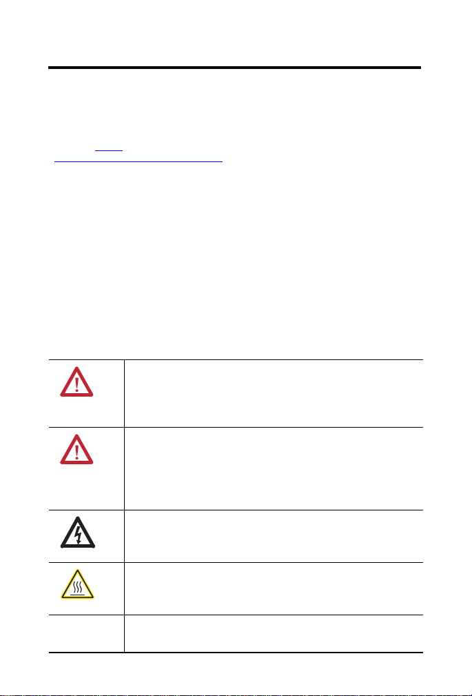
IMPORTANT
Important User Information
Solid state equipment has operational characteristics differing from those of electromechanical
equipment. Safety Guidelines for the Application, Installation and Maintenance of Solid State Controls
(Publication SGI-1.1
http://www.rockwellautomation.com/literature.)
state equipment and hard-wired electromechanical devices. Because of this difference, and also because
of the wide variety of uses for solid state equipment, all persons responsible for applying this equipment
must satisfy themselves that each intended application of this equipment is acceptable.
In no event will Rockwell Automation, Inc. be responsible or liable for indirect or consequential damages
resulting from the use or application of this equipment.
The examples and diagrams in this manual are included solely for illustrative purposes. Because of the
many variables and requirements associated with any particular installation, Rockwell Automation, Inc.
cannot assume responsibility or liability for actual use based on the examples and diagrams.
No patent liability is assumed by Rockwell Automation, Inc. with respect to use of information, circuits,
equipment, or software described in this manual.
Reproduction of the contents of this manual, in whole or in part, without written permission of Rockwell
Automation, Inc., is prohibited.
Throughout this manual, when necessary, we use notes to make you aware of safety considerations.
available from your local Rockwell Automation sales office or online at
describes some important differences between solid
WARNING: Identifies information about practices or
circumstances that can cause an explosion in a hazardous
environment, which may lead to personal injury or death,
property damage, or economic loss.
ATTENTION: Identifies information about practices or
circumstances that can lead to personal injury or death,
property damage, or economic loss. Attentions help you
identify a hazard, avoid a hazard and recognize the
consequences.
SHOCK HAZARD: Labels may be on or inside the
equipment to alert people that dangerous voltage may be
present.
BURN HAZARD: Labels may be on or inside the
equipment to alert people that surfaces may reach
dangerous temperatures.
Identifies information that is critical for successful
application and understanding of the product.
Rockwell Automation Publication 1756-IN610B-EN-P - November 2010
Page 3

Environment and Enclosure
ATTENTION: This equipment is intended for use in a
Pollution Degree 2 industrial environment, in overvoltage
Category II applications (as defined in IEC 60664-1), at
altitudes up to 2000 m (6562 ft) without derating.
This equipment is considered Group 1, Class A industrial
equipment according to IEC/CISPR 11. Without appropriate
precautions, there may be difficulties with electromagnetic
compatibility in residential and other environments due to
conducted and radiated disturbances.
This equipment is supplied as open-type equipment. It must be
mounted within an enclosure that is suitably designed for those
specific environmental conditions that will be present and
appropriately designed to prevent personal injury resulting from
accessibility to live parts. The enclosure must have suitable
flame-retardant properties to prevent or minimize the spread of
flame, complying with a flame spread rating of 5VA, V2, V1, V0
(or equivalent) if non-metallic. The interior of the enclosure must
be accessible only by the use of a tool. Subsequent sections of
this publication may contain additional information regarding
specific enclosure type ratings that are required to comply with
certain product safety certifications.
In addition to this publication, see the following:
• Industrial Automation Wiring and Grounding Guidelines,
Allen-Bradley publication 1770-4.1
requirements
• NEMA Standard 250 and IEC 60529, as applicable, for
explanations of the degrees of protection provided by
different types of enclosure
ControlLogix Remote I/O (RIO) Module 3
, for additional installation
Rockwell Automation Publication 1756-IN610B-EN-P - November 2010
Page 4
4 ControlLogix Remote I/O (RIO) Module
Prevent Electrostatic Discharge
ATTENTION: This equipment is sensitive to electrostatic
discharge, which can cause internal damage and affect
normal operation. Follow these guidelines when you handle
this equipment:
• Touch a grounded object to discharge potential static.
• Wear an approved grounding wriststrap.
• Do not touch connectors or pins on component boards.
• Do not touch circuit components inside the equipment.
• Use a static-safe workstation, if available.
• Store the equipment in appropriate static-safe packaging
when not in use.
ATTENTION: If this equipment is used in a manner not specified
by the manufacturer, the protection provided by the equipment may
be impaired.
Rockwell Automation Publication 1756-IN610B-EN-P - November 2010
Page 5
ControlLogix Remote I/O (RIO) Module 5
Removal and Insertion Under Power
WARNING: When you insert or remove the module while
backplane power is on, an electrical arc can occur. This could
cause an explosion in hazardous location installations. Be sure
that power is removed or the area is nonhazardous before
proceeding. Repeated electrical arcing causes excessive wear to
contacts on both the module and its mating connector. Worn
contacts may create electrical resistance that can affect module
operation.
Multi-point Network Communication Connections
WARNING: If you connect or disconnect the communication cable
with power applied to this module or any device on the network, an
electrical arc can occur. This could cause an explosion in hazardous
location installations. Be sure that power is removed or the area is
nonhazardous before proceeding.
Rockwell Automation Publication 1756-IN610B-EN-P - November 2010
Page 6
6 ControlLogix Remote I/O (RIO) Module
North American Hazardous Location Approval
The following information applies
when operating this equipment in
hazardous locations:
Products marked ‘CL I, DIV 2, GP A, B, C, D’ are
suitable for use in Class I Division 2 Groups A, B,
C, D, Hazardous Locations and nonhazardous
locations only. Each product is supplied with
markings on the rating nameplate indicating the
hazardous location temperature code. When
combining products within a system, the most
adverse temperature code (lowest ‘T’ number) may
be used to help determine the overall temperature
code of the system. Combinations of equipment in
your system are subject to investigation by the
local Authority Having Jurisdiction at the time of
installation.
WARNING:
EXPLOSION HAZARD –
•Do not disconnect equipment
unless power has been
removed or the area is known
to be nonhazardous.
• Do not disconnect connections
to this equipment unless
power has been removed or
the area is known to be
nonhazardous.Secure any
external connections that mate
to this equipment by using
screws, sliding latches,
threaded connectors, or other
means provided with this
product.
•Substitution of components
may impair suitability for Class
I, Division 2.
•If this product contains
batteries, they must only be
changed in an area known to
be nonhazardous.
Informations sur l’utilisation de cet
équipement en environnements
dangereux:
Les produits marqués ‘CL I, DIV 2, GP A, B, C, D’ ne
conviennent qu'à une utilisation en environnements
de Classe I Division 2 Groupes A, B, C, D dangereux
et non dangereux. Chaque produit est livré avec des
marquages sur sa plaque d'identification qui
indiquent le code de température pour les
environnements dangereux. Lorsque plusieurs
produits sont combinés dans un système, le code de
température le plus défavorable (code de
température le plus faible) peut être utilisé pour
déterminer le code de température global du
système. Les combinaisons d'équipements dans le
système sont sujettes à inspection par les autorités
locales qualifiées au moment de l'installation.
AVERTISSEMENT:
RISQUE D’EXPLOSION –
•Couper le courant ou
s'assurer que
l'environnement est classé
non dangereux avant de
débrancher l'équipement.
•Couper le courant ou
s'assurer que
l'environnement est classé
non dangereux avant de
débrancher les
connecteurs.Fixer tous les
connecteurs externes reliés à
cet équipement à l'aide de
vis, loquets coulissants,
connecteurs filetés ou autres
moyens fournis avec ce
produit.
•La substitution de
composants peut rendre cet
équipement inadapté à une
utilisation en environnement
de Classe I, Division 2.
•S'assurer que
l'environnement est classé
non dangereux avant de
changer les piles.
Rockwell Automation Publication 1756-IN610B-EN-P - November 2010
Page 7

ControlLogix Remote I/O (RIO) Module 7
IMPORTANT
About the Module
The ControlLogix 1756-RIO module connects a ControlLogix processor to a
remote I/O network.
The module can act as a scanner or as an adapter on the network. For additional
information, see publication 1756-UM534
This module is shipped in scanner mode, with a blank
configuration.
.
1756-RIO Module as a Scanner
As a scanner, with one remote I/O channel, the 1756-RIO module scans I/O on
a remote I/O network.
The module supports the following:
• All remote I/O baud rates: 57.6, 115.2, 230.4 Kbaud
• Rack numbers from 0…76 octal
• All combinations of partial racks
• Up to 32 physical adapters
To support 32 physical adapters, you must use an 82 resistor; 150
resistors allow only 16 adapters.
The module can update block transfers (BTs) automatically via the 1756-RIO
module or can be controlled by the ControlLogix controller. It transfers all I/O
via produced/consumed connections over the backplane to the controller.
• Block transfers at all possible locations
Rockwell Automation Publication 1756-IN610B-EN-P - November 2010
Page 8

8 ControlLogix Remote I/O (RIO) Module
IMPORTANT
1756-RIO Module as an Adapter
As an adapter, the 1756-RIO module lets the controller exchange data with or
monitor an existing scanner. The module supports the following features:
• Has one remote I/O channel
• Emulates one or more racks
• All remote I/O baud rates: 57.6, 115.2, 230.4 Kbaud
• Rack numbers from 0…76 octal
• All combinations of partial racks
• Block transfers at all possible locations
• Can monitor I/O on a network with an existing remote I/O scanner
(Monitor Mode)
• Transfers all I/O to the controller via produced/consumed connections
over the backplane to the controller.
The module firmware can be updated using the Windows utilities
software supplied with the module.
Rockwell Automation Publication 1756-IN610B-EN-P - November 2010
Page 9

ControlLogix Remote I/O (RIO) Module 9
Before You Begin
Before you install your I/O module, you should do the following:
• Identify the module components. See page
• Note the power requirements. See page 11.
• Install and connect a ControlLogix chassis and power supply. See
publication 1756-IN080.
• Install RSLogix 5000 programming software, version 17 or later, and the
associated firmware.
• Install RSLinx software, version 2.54 or later, with an activation. Use
RSLinx Gateway software or RSLinx Professional software. Do not use
RSLinx Lite.
• Install the 1756-RIO module Add-on Profile from the CD provided
with the module.
• Determine the slot location. You can install the module in any slot in any
size ControlLogix chassis. See page
• The 1756-RIO/B module requires firmware revision 3.1 or above.
10.
12.
Rockwell Automation Publication 1756-IN610B-EN-P - November 2010
Page 10

10 ControlLogix Remote I/O (RIO) Module
IMPORTANT
44777
1
2
3
4
43161
RIO CLX OK
2
1
Module Components
2
Clr
1
Blue
1756-RIO/B
Rockwell Automation Publication 1756-IN610B-EN-P - November 2010
Item Description
1 4-character scrolling display
2 Three status indicators:
• RIO indicates the status of the remote I/O network
• CLX indicates the status of the connection to the processor
• OK indicates the module’s own internal state
3 3-pin connector (blue hose) that connects to the remote devices
This is also known as the removable terminal block (RTB).
4 Inside-door label with error codes
Note that a cable from a 1756-RIO/A module will plug directly
into a 1756-RIO/B module, but it is rotated 180°.
Page 11

ControlLogix Remote I/O (RIO) Module 11
Power Requirements
This module receives power from the 1756-chassis power supply and requires
two sources of power from the ControlLogix backplane.
• 450 mA at 5.1V DC
• 5 mA at 24V DC
Add these current/power values (2.5 W) to the requirements of all other
modules in the chassis to prevent overloading the power supply.
Install the Module
You can install or remove the module while chassis power is applied if you
observe these precautions.
WARNING: When you insert or remove the module while
backplane power is on, an electrical arc can occur. If you connect
or disconnect the communications cable with power applied to
this module or any device on the network, an electrical arc can
occur. This could cause an explosion in hazardous location
installations. Be sure that power is removed or the area is
nonhazardous before proceeding. Repeated electrical arcing
causes excessive wear to contacts on both the module and its
mating connector. Worn contacts may create electrical resistance
that can affect module operation.
For this installation, we will assume chassis power is off.
Rockwell Automation Publication 1756-IN610B-EN-P - November 2010
Page 12

12 ControlLogix Remote I/O (RIO) Module
Installing and Connecting a Chassis
Before installing the module, you must install and connect a ControlLogix
chassis and power supply. See ControlLogix Chassis Installation Instructions,
publication 1756-IN080
To determine the slot location in the chassis, remember that chassis slots are
numbered starting from the left, at 0. Slot 0 is the first slot to the right of the
power supply.
You can do the following:
• Use any size chassis.
• Install the module in any available slot.
• Install multiple 1756-RIO modules in the same chassis, depending on
how your power supply is rated.
.
Rockwell Automation Publication 1756-IN610B-EN-P - November 2010
Page 13
ControlLogix Remote I/O (RIO) Module 13
Printed
Circuit
Board
20861
Install the Module in the Chassis
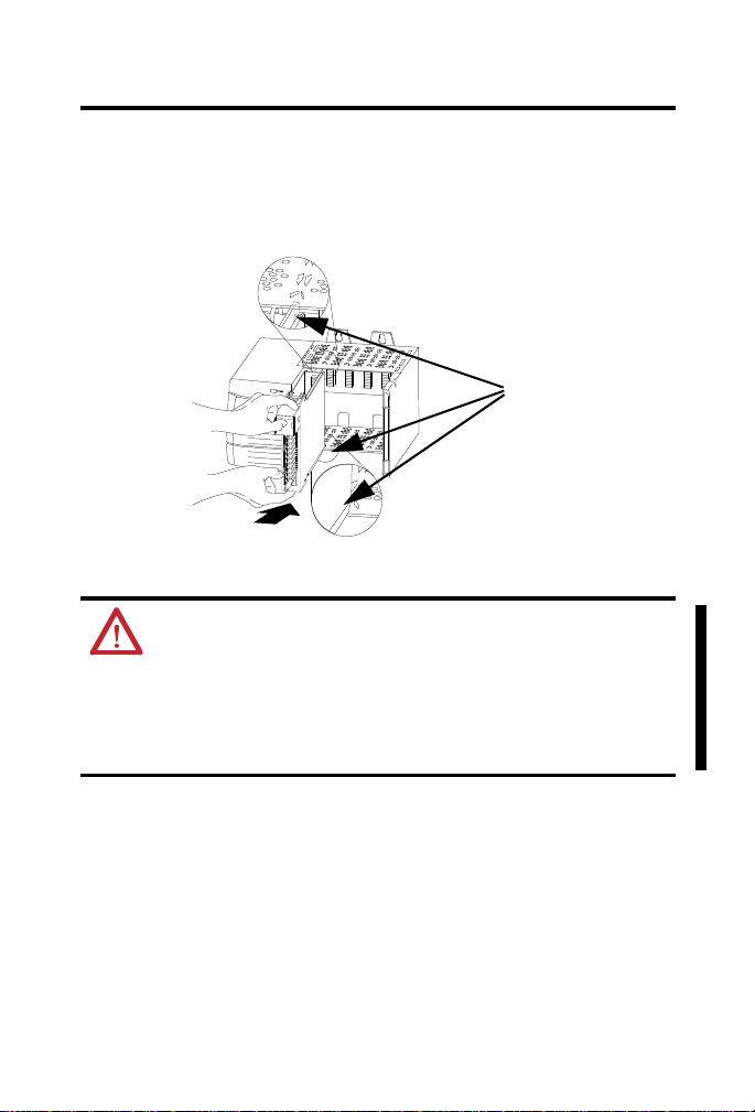
To install the module, follow these steps.
1. Align the circuit board with the top and bottom chassis guides.
WARNING: When you insert or the remove the module while
backplane power is on, an electrical arc can occur. This could cause
an explosion in hazardous location installations. Be sure that
power is removed or the area is nonhazardous before proceeding.
Repeated electrical arcing causes excessive wear to contacts on
both the module and its mating connector. Worn contacts may
create electrical resistance that can affect module operation.
Rockwell Automation Publication 1756-IN610B-EN-P - November 2010
Page 14

14 ControlLogix Remote I/O (RIO) Module
Locking Tab
20862
2. Slide the module into the chassis until the module locking tabs click.
ATTENTION: Do not force the module into the backplane
connector. If you cannot seat the module with firm pressure,
check the alignment. Forcing the module into the chassis can
damage the backplane connector or the module. The module is
fully installed when it is flush with the power supply or other
installed modules.
Rockwell Automation Publication 1756-IN610B-EN-P - November 2010
Page 15

ControlLogix Remote I/O (RIO) Module 15
1
2
44776
1 (Blue)
2 (Clear)
(Shield)
Install the Removable Terminal Block (RTB)
Push the removable terminal block (RTB) into the 3-pin connector.
WARNING: If you connect or disconnect the communication cable
with power applied to this module or any device on the network, an
electrical arc can occur. This could cause an explosion in hazardous
location installations. Be sure that power is removed or the area is
nonhazardous before proceeding.
Rockwell Automation Publication 1756-IN610B-EN-P - November 2010
Page 16

16 ControlLogix Remote I/O (RIO) Module
Wire the Connector for the Remote I/O Network
To wire the connector for the remote I/O network, refer to the Cabling and
Termination table and follow these steps.
Cabling and Termination
Connector Pin Description
1 (bottom) Line 1 (blue)
N/A Shield
2 Line 2 (clear)
1. Connect Line 1 (blue) of the remote I/O cable to the lower pin on the
1756-RIO module.
2. Connect the shield to the middle pin.
3. Connect Line 2 (clear) of the remote I/O cable to the upper pin on the
1756-RIO module.
4. Terminate both ends of a remote I/O network by using external resistors
attached to the physical ends of the network.
There should be two terminators at the ends network. The terminator is
connected between Line 1 (blue) and line 2 (clear).
Rockwell Automation Publication 1756-IN610B-EN-P - November 2010
Page 17

ControlLogix Remote I/O (RIO) Module 17
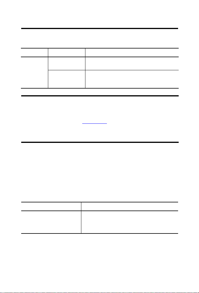
Select the Proper Resistor
Use 82 resistors if the network operates at 230.4 kbps or if the network
operates at 57.6 kbps, or 115.2 kbps and none of the devices in this table are
present. The maximum number of devices on the network is 32.
Use 150 resistors if the network contains any of the devices in this table, or if
the network operates at 57.6 kbps or 115.2 kbps and you do not require the
network to support more than 16 devices.
Device Resistors
Cat. No. Series
1747-ASB All
1771-AS All
1771-ASB Series A
1775-S5 All
1794-ASB All
1771-DCM All
1771-SN All
1772-SD All
1772-SD2 All
1775-S4A All
1775-S4B All
1775-SR5 All
Baud Rate Cable Limits
Baud Rate Maximum Cable Length
57.6 Kbaud 3048 m (10000 ft)
115.2 Kbaud 1524 m (5000 ft)
230.4 Kbaud 762 m (2500 ft)
Rockwell Automation Publication 1756-IN610B-EN-P - November 2010
Page 18

18 ControlLogix Remote I/O (RIO) Module
Apply Chassis Power
Turn on the chassis power supply.
Check Power Supply and Module Status
The following indicates the correct power supply status and display indicators
for the 1756-RIO module.
Chassis Power-supply Status Indicators
The chassis power-supply indicator should be green. The module OK status
indicator should be solid red immediately after you turn on the chassis power
supply and then it turns solid green. Refer to the installation instructions for
your particular 1756-chassis power supply for recommended actions for
checking your power supply.
Alphanumeric Display at Powerup
The 4-character, alphanumeric display shows either ‘RIO Scanner’ or ‘RIO
Adapter’, followed by the firmware version number, and any banner text defined
in the module configuration.
The display shows the following messages at powerup.
Message Description
B#nn Stages in the start-up processes; nn is a hexadecimal number
Boot Next stage in power-up sequence
RIO Scanner v. x.xx.xx Module firmware revision
If the indicator on the 1756-RIO module does not cycle through these messages
on powerup, refer to the Troubleshooting section of the 1756 RIO user manual,
publication 1756-UM534
Rockwell Automation Publication 1756-IN610B-EN-P - November 2010
.
Page 19

ControlLogix Remote I/O (RIO) Module 19
44777
RIO CLX OK
Module Status Indicators
The module has three status indicators to indicate the state of internal
operations. The status indicators are labeled RIO, CLX, and OK.
RIO Status Indicator – Remote Devices Status
The RIO indicator displays the status of the remote I/O network connection.
Status varies depending on the mode of the module.
Scanner Mode
This table shows status in order of priority, highest first.
Indicator Status Description
RIO Red A frame-receive error has been received in the last
Flashing red/off At least one rack that is being scanned (not inhibited)
Yel low Idle, no racks are configured.
Flashing yellow/off All configured racks are inhibited.
Flashing green/off No racks being scanned (not inhibited) are in error, but
Green Successful communication with all configured racks,
second (CRC error, abort, or time-out). Indicator stays
red for one second after the error occurs.
One or more racks are in error.
is in error. One or more racks are inhibited.
one or more racks are inhibited.
no inhibited racks.
Rockwell Automation Publication 1756-IN610B-EN-P - November 2010
Page 20

20 ControlLogix Remote I/O (RIO) Module
Adapter Mode
This table shows status in order of priority, highest first.
Indicator Status Description
RIO Red A frame-receive error has been received in the last
Flashing red/off One or more racks are not being scanned.
Flashing green/off Configuration mismatch on one or more racks.
Green All racks are being scanned and there are no
second (CRC error, abort, or time-out). Indicator stays
red for one second after the error occurs.
configuration mismatches.
CLX Status Indicator – ControlBus Status
The CL X indicator d isplays the status of communication with th e ControlLog ix
processor.
Indicator Status Description
CLX
Green The module has successfully processed a request
Flashing green/off Controlling Connection is open, but not all required
Yel low Idle, no requests received from the backplane in the
Flashing yellow/off Controlling Connection is not open.
Red The module has returned a CIP error to a request from
Flashing red/off The module has returned a CIP error within the last
from the ControlBus backplane within the last five
seconds. All required connections are open.
connections are open.
last five seconds. No connections; empty
configuration.
the backplane within the last second. All required
connections are open.
second. All required connections are not open.
Rockwell Automation Publication 1756-IN610B-EN-P - November 2010
Page 21
ControlLogix Remote I/O (RIO) Module 21
IMPORTANT
OK Status Indicator – Module Health
Indicator Status Description
OK Green Indicates that module has passed all power-up
Red Indicates that module start-up diagnostics have
diagnostics and is functioning normally.
failed or a major module fault, such as watchdog
time-out or jabber inhibit, has occurred.
If all three status indicators are solid red and the 4-character
display shows M#xx, (where xx is the error number), a fatal
error has occurred. Refer to the 1756-RIO user manual,
publication 1756-UM534
, for information on clearing fatal
errors. Make a note of the error code numbers to give
Technical Support, if you need to call for help.
Interpret the Alphanumeric Display
The remote I/O (RIO) communication interface module displays alphanumeric
messages that provide diagnostic information about your module. The warning
messages appear twice on the display, then the normal display resumes. The table
summarizes the messages.
Alphanumeric Display Message Descriptions
Message Description
RIO Scanner v. x.xx.xx [banner]
RIO Adapter v. x.xx.xx [banner]
Rockwell Automation Publication 1756-IN610B-EN-P - November 2010
The module’s firmware revision, displayed at powerup.
The three parts of the revision number are the major
revision, the minor revision, and the build number. This
is followed by the status banner.
Page 22

22 ControlLogix Remote I/O (RIO) Module
44776
1
2
Configure the Module
Once installed, your 1756-RIO module must be configured. Refer to the
1756-RIO user manual, publication 1756-UM534, for information on module
configuration.
Uninstall the Removable Terminal Block (RTB)
To remove the RTB, grasp firmly and pull out.
WARNING: If you connect or disconnect the communication cable
with power applied to this module or any device on the network, an
electrical arc can occur. This could cause an explosion in hazardous
location installations. Be sure that power is removed or the area is
nonhazardous before proceeding.
Rockwell Automation Publication 1756-IN610B-EN-P - November 2010
Page 23

ControlLogix Remote I/O (RIO) Module 23
20856
20857
Uninstall the Module
WARNING: When you insert or the remove the module while
backplane power is on, an electrical arc can occur. This could cause
an explosion in hazardous location installations. Be sure that
power is removed or the area is nonhazardous before proceeding.
Repeated electrical arcing causes excessive wear to contacts on
both the module and its mating connector. Worn contacts may
create electrical resistance that can affect module operation.
To remove the module, follow the steps below.
1. Push in top and bottom locking tab.
2. Pull the module out of the chassis.
Rockwell Automation Publication 1756-IN610B-EN-P - November 2010
Page 24

24 ControlLogix Remote I/O (RIO) Module
Replacing the Module
If you are replacing an existing module with an identical one, and you want to
resume identical system operation, you must do the following:
• Install the new module in the same slot.
• Run the configuration program and download the appropriate
configuration to the module.
• Check that the module has the correct firmware, scanner, or adapter
version.
Rockwell Automation Publication 1756-IN610B-EN-P - November 2010
Page 25

ControlLogix Remote I/O (RIO) Module 25
Specifications
Technical Specifications - 1756-RIO
Attribute 1756-RIO
Module location 1756 ControlLogix chassis
Backplane current, max 450 mA @ 5.1V DC
5 mA @ 24 V DC
Isolation voltage 50V (continuous), basic insulation type, RIO
Power dissipation 2.5 W
Screw terminal torque 0.5…0.6 N•m (5…7 lb•in)
Wiring category
(1)
Wire size 0.52 mm
Wire type Belden 9463 twinaxial
Enclosure type rating None (open-style)
North American temperature code T4A
(1) Use this Conductor Category information for planning conductor routing. Refer to Industrial
Automation Wiring and Grounding Guidelines, publication 1770-4.1
communication lines to backplane.
Type tested at 500V AC for 60 s
2 - on communication ports
2
(20 AWG)
.
Rockwell Automation Publication 1756-IN610B-EN-P - November 2010
Page 26

26 ControlLogix Remote I/O (RIO) Module
Environmental Specifications - 1756-RIO
Attribute 1756-RIO
Operating temperature
IEC 60068-2-1 (Test Ad, Operating Cold)
IEC 60068-2-2 (Test Bd, Operating Dry Heat)
IEC 60068-2-14 (Test Nb, Operating Thermal Shock)
Nonoperating temperature
IEC 60068-2-1 (Test Ab, Unpackaged Nonoperating
Cold)
IEC 60068-2-2 (Test Bb, Unpackaged Nonoperating
Dry Heat)
IEC 60068-2-14 (Test Na, Unpackaged
Nonoperating Thermal Shock)
Surrounding air temperature, max 60 °C (140 °F)
Relative humidity
IEC 60068-2-30 (Test Db, Unpackaged Damp Heat)
Operating shock
IEC 60068-2-27 (Test Ea, Unpackaged Shock)
Nonoperating shock
IEC 60068-2-27 (Test Ea, Unpackaged Shock)
Vibration
IEC 60068-2-6 (Test Fc, Operating)
Emissions
CISPR 11
ESD immunity
IEC 61000-4-2
Radiated RF immunity
IEC 61000-4-3
0…60 °C (32…140 °F)
-40…85 °C (-40…185 °F)
5…95% noncondensing
30 g
50 g
2 g @ 10…500 Hz
Group 1, Class A
6 kV contact discharges
8 kV air discharges
10V/m with 1 kHz sine-wave 80%
AM from 80…2000 MHz
10V/m with 200 Hz 50% Pulse 100%
AM at 900 Mhz
10V/m with 200 Hz 50% Pulse 100%
AM at 1890 MHz
3V/m with 1 kHz sine-wave 80% AM
from 2000…2700 MHz
Rockwell Automation Publication 1756-IN610B-EN-P - November 2010
Page 27

Environmental Specifications - 1756-RIO
Attribute 1756-RIO
EFT/B immunity
IEC 61000-4-4
Surge transient immunity
IEC 61000-4-5
Conducted RF immunity
IEC 61000-4-6
±2 kV at 5 kHz on communication
ports
± 2 kV line-earth (CM) on
communication ports
10V rms with 1 kHz sine-wave 80%
AM from 150 kHz…80 MHz
Certifications
Certification
(1)
- 1756-RIO
(2)
1756-RIO
c-UL-us UL Listed Industrial Control Equipment, certified for U.S. and Canada.
See UL File E65584.
UL listed for Class 1, Division 2 Group A,B,C,D Hazardous Locations,
certified for U.S. and Canada. See UL File E194810.
CE European Union 2004/108/EC EMC Directive, compliant with:
• EN 61326-1; Meas./Control/Lab., Industrial Requirements
• EN 61000-6-2; Industrial Immunity
• EN 61000-6-4; Industrial Emissions
• EN 61131-2; Programmable Controllers (Clause 8, Zone A & B)
C-Tick Australian Radiocommunications Act, compliant with:
(1) When product is marked.
(2) See the Product Certification link at http://www.ab.com
and other certification details.
• AS/NZS CISPR 11; Industrial Emissions
for Declarations of Conformity, Certificates,
Page 28
Rockwell Otomasyon Ticaret A.Ş., Kar Plaza İş Merkezi E Blok Kat:6 34752 İçerenköy, İstanbul, Tel: +90 (216) 5698400
Additional Resources
These documents contain additional information concerning related Rockwell
Automation products.
Resource Description
Industrial Automation Wiring and Grounding
Guidelines, publication 1770-4.1
Product Certification website,
http://www.ab.com
You can view or download publications at
http://www.rockwellautomation.com/literature
technical documentation, contact your local Rockwell Automation distributor
or sales representative.
Provides general guidelines for installing a
Rockwell Automation industrial system.
Provides declarations of conformity,
certificates, and other certification details.
. To order paper copies of
Allen-Bradley, Rockwell Software, Rockwell Automation, ControlLogix , RSLogix 5000, R SLinx, and TechConnect are trademarks
of Rockwell Automation, Inc.
Trademarks not belonging to Ro ckwell Automation are property of their respective companies.
Publication 1756-IN610B-EN-P - November 2010 PN-92344
Supersedes Publication 1756-IN610A-EN-P - March 2009 Copyright © 2010 Rockwell Automation, Inc. All rights reserved. Printed in the U.S.A.
 Loading...