

Page 1

User Manual
ControlLogix Eight-channel Isolated Analog I/O Modules
Catalog Numbers 1756-IF8I, 1756-IRT8I, 1756-OF8I
Page 2
Important User Information
IMPORTANT
Read this document and the documents listed in the additional resources section about installation, configuration, and
operation of this equipment before you install, configure, operate, or maintain this product. Users are required to
familiarize themselves with installation and wiring instructions in addition to requirements of all applicable codes, laws,
and standards.
Activities including installation, adjustments, putting into service, use, assembly, disassembly, and maintenance are required
to be carried out by suitably trained personnel in accordance with applicable code of practice.
If this equipment is used in a manner not specified by the manufacturer, the protection provided by the equipment may be
impaired.
In no event will Rockwell Automation, Inc. be responsible or liable for indirect or consequential damages resulting from the
use or application of this equipment.
The examples and diagrams in this manual are included solely for illustrative purposes. Because of the many variables and
requirements associated with any particular installation, Rockwell Automation, Inc. cannot assume responsibility or
liability for actual use based on the examples and diagrams.
No patent liability is assumed by Rockwell Automation, Inc. with respect to use of information, circuits, equipment, or
software described in this manual.
Reproduction of the contents of this manual, in whole or in part, without written permission of Rockwell Automation,
Inc., is prohibited.
Throughout this manual, when necessary, we use notes to make you aware of safety considerations.
WARNING: Identifies information about practices or circumstances that can cause an explosion in a hazardous environment,
which may lead to personal injury or death, property damage, or economic loss.
ATTENTION: Identifies information about practices or circumstances that can lead to personal injury or death, property
damage, or economic loss. Attentions help you identify a hazard, avoid a hazard, and recognize the consequence.
Identifies information that is critical for successful application and understanding of the product.
Labels may also be on or inside the equipment to provide specific precautions.
SHOCK HAZARD: Labels may be on or inside the equipment, for example, a drive or motor, to alert people that dangerous
voltage may be present.
BURN HAZARD: Labels may be on or inside the equipment, for example, a drive or motor, to alert people that surfaces may
reach dangerous temperatures.
ARC FLASH HAZARD: Labels may be on or inside the equipment, for example, a motor control center, to alert people to
potential Arc Flash. Arc Flash will cause severe injury or death. Wear proper Personal Protective Equipment (PPE). Follow ALL
Regulatory requirements for safe work practices and for Personal Protective Equipment (PPE).
Allen-Bradley, ControlLogix, Integrated Architecture, Logix Designer, Logix5000, Rockwell Software, Rockwell Automation, RSLogix, Studio 5000, an d Studio 5000 Log ix Designer are trademarks of Rockwell Automation,
Inc.
Trademarks not belonging to Rockwell Automation are property of their respective companies.
Page 3

Table of Contents
Preface
Isolated Analog I/O Module
Operation in the
ControlLogix System
ControlLogix Isolated Analog I/O
Module Features
Studio 5000 Environment . . . . . . . . . . . . . . . . . . . . . . . . . . . . . . . . . . . . . . . . . . 7
Additional Resources . . . . . . . . . . . . . . . . . . . . . . . . . . . . . . . . . . . . . . . . . . . . . . . 8
Chapter 1
Before You Begin . . . . . . . . . . . . . . . . . . . . . . . . . . . . . . . . . . . . . . . . . . . . . . . . . . 9
Ownership . . . . . . . . . . . . . . . . . . . . . . . . . . . . . . . . . . . . . . . . . . . . . . . . . . . . . . 11
Configure a Module . . . . . . . . . . . . . . . . . . . . . . . . . . . . . . . . . . . . . . . . . . . . . . 11
Direct Connections . . . . . . . . . . . . . . . . . . . . . . . . . . . . . . . . . . . . . . . . . . . . . . 12
Input Module Operation . . . . . . . . . . . . . . . . . . . . . . . . . . . . . . . . . . . . . . . . . 14
Requested Packet Interval (RPI) . . . . . . . . . . . . . . . . . . . . . . . . . . . . . . . 14
Input Modules in a Local Chassis . . . . . . . . . . . . . . . . . . . . . . . . . . . . . . 15
Input Modules in a Remote Chassis. . . . . . . . . . . . . . . . . . . . . . . . . . . . 15
Triggering Event Tasks . . . . . . . . . . . . . . . . . . . . . . . . . . . . . . . . . . . . . . . 16
Output Module Operation . . . . . . . . . . . . . . . . . . . . . . . . . . . . . . . . . . . . . . . 17
Output Modules in a Local Chassis . . . . . . . . . . . . . . . . . . . . . . . . . . . . 17
Output Modules in a Remote Chassis . . . . . . . . . . . . . . . . . . . . . . . . . . 17
Listen-only Mode . . . . . . . . . . . . . . . . . . . . . . . . . . . . . . . . . . . . . . . . . . . . . . . . 18
Chapter 2
Common Analog I/O Features. . . . . . . . . . . . . . . . . . . . . . . . . . . . . . . . . . . . 20
CIP Sync Timestamp of Data . . . . . . . . . . . . . . . . . . . . . . . . . . . . . . . . . 20
Rolling Timestamp of Data . . . . . . . . . . . . . . . . . . . . . . . . . . . . . . . . . . . 21
Floating Point Data Format . . . . . . . . . . . . . . . . . . . . . . . . . . . . . . . . . . . 22
Module Resolution . . . . . . . . . . . . . . . . . . . . . . . . . . . . . . . . . . . . . . . . . . . 22
Module Quality Reporting . . . . . . . . . . . . . . . . . . . . . . . . . . . . . . . . . . . . 23
Calibration . . . . . . . . . . . . . . . . . . . . . . . . . . . . . . . . . . . . . . . . . . . . . . . . . . 24
Fault and Status Reporting . . . . . . . . . . . . . . . . . . . . . . . . . . . . . . . . . . . . 24
Configurable Software . . . . . . . . . . . . . . . . . . . . . . . . . . . . . . . . . . . . . . . . 25
Latching of Alarms . . . . . . . . . . . . . . . . . . . . . . . . . . . . . . . . . . . . . . . . . . . 26
Module Inhibiting. . . . . . . . . . . . . . . . . . . . . . . . . . . . . . . . . . . . . . . . . . . . 26
Electronic Keying . . . . . . . . . . . . . . . . . . . . . . . . . . . . . . . . . . . . . . . . . . . . 28
Exact Match . . . . . . . . . . . . . . . . . . . . . . . . . . . . . . . . . . . . . . . . . . . . . . . . . 30
Compatible Keying . . . . . . . . . . . . . . . . . . . . . . . . . . . . . . . . . . . . . . . . . . . 31
Disabled Keying. . . . . . . . . . . . . . . . . . . . . . . . . . . . . . . . . . . . . . . . . . . . . . 33
Relationship between Module Resolution and Scaling. . . . . . . . . . . . . . . 35
Module Resolution . . . . . . . . . . . . . . . . . . . . . . . . . . . . . . . . . . . . . . . . . . . 35
Scaling. . . . . . . . . . . . . . . . . . . . . . . . . . . . . . . . . . . . . . . . . . . . . . . . . . . . . . . 37
Calibration . . . . . . . . . . . . . . . . . . . . . . . . . . . . . . . . . . . . . . . . . . . . . . . . . . . . . . 38
Calibrated Accuracy. . . . . . . . . . . . . . . . . . . . . . . . . . . . . . . . . . . . . . . . . . . . . . 38
Calibrated Accuracy at 25 °C (77 °F). . . . . . . . . . . . . . . . . . . . . . . . . . . 38
Module Error over Full Temperature Range . . . . . . . . . . . . . . . . . . . . 39
Error Calculated over Hardware Range . . . . . . . . . . . . . . . . . . . . . . . . . . . . 39
Rockwell Automation Publication 1756-UM540A-EN-P - May 2014 3
Page 4

Table of Contents
RTD and Thermocouple Error Calculations. . . . . . . . . . . . . . . . . . . . . . . . 39
RTD Error. . . . . . . . . . . . . . . . . . . . . . . . . . . . . . . . . . . . . . . . . . . . . . . . . . . 40
Thermocouple Error . . . . . . . . . . . . . . . . . . . . . . . . . . . . . . . . . . . . . . . . . . 41
Module Error at 25 °C (77 °F) . . . . . . . . . . . . . . . . . . . . . . . . . . . . . . . . . 42
Thermocouple Resolution . . . . . . . . . . . . . . . . . . . . . . . . . . . . . . . . . . . . . . . . 43
Chapter 3
1756-IF8I Isolated Analog
Input Module
1756-IRT8I Combined
Temperature-sensing
Isolated Analog Module
1756-IF8I Module Features . . . . . . . . . . . . . . . . . . . . . . . . . . . . . . . . . . . . . . . 45
Internal Loop Power Source . . . . . . . . . . . . . . . . . . . . . . . . . . . . . . . . . . . 46
Multiple Input Ranges . . . . . . . . . . . . . . . . . . . . . . . . . . . . . . . . . . . . . . . . 47
Notch Filter. . . . . . . . . . . . . . . . . . . . . . . . . . . . . . . . . . . . . . . . . . . . . . . . . . 48
Underrange/Overrange Detection . . . . . . . . . . . . . . . . . . . . . . . . . . . . . 51
Digital Filter . . . . . . . . . . . . . . . . . . . . . . . . . . . . . . . . . . . . . . . . . . . . . . . . . 52
Process Alarms . . . . . . . . . . . . . . . . . . . . . . . . . . . . . . . . . . . . . . . . . . . . . . . 53
Rate Alarm. . . . . . . . . . . . . . . . . . . . . . . . . . . . . . . . . . . . . . . . . . . . . . . . . . . 55
Sensor Offset. . . . . . . . . . . . . . . . . . . . . . . . . . . . . . . . . . . . . . . . . . . . . . . . . 55
Wire Off Detection. . . . . . . . . . . . . . . . . . . . . . . . . . . . . . . . . . . . . . . . . . . 56
Synchronized Sampling . . . . . . . . . . . . . . . . . . . . . . . . . . . . . . . . . . . . . . . 57
Module Block and Circuit Diagrams . . . . . . . . . . . . . . . . . . . . . . . . . . . . . . . 58
Field-side Circuit Diagrams. . . . . . . . . . . . . . . . . . . . . . . . . . . . . . . . . . . . 59
Wire the 1756-IF8I Module. . . . . . . . . . . . . . . . . . . . . . . . . . . . . . . . . . . . . . . 61
Fault and Status Reporting . . . . . . . . . . . . . . . . . . . . . . . . . . . . . . . . . . . . . . . . 64
Chapter 4
1756-IRT8I Module Features . . . . . . . . . . . . . . . . . . . . . . . . . . . . . . . . . . . . . 65
Multiple Input Ranges . . . . . . . . . . . . . . . . . . . . . . . . . . . . . . . . . . . . . . . . 66
Notch Filter. . . . . . . . . . . . . . . . . . . . . . . . . . . . . . . . . . . . . . . . . . . . . . . . . . 67
Underrange/Overrange Detection . . . . . . . . . . . . . . . . . . . . . . . . . . . . . 70
Digital Filter . . . . . . . . . . . . . . . . . . . . . . . . . . . . . . . . . . . . . . . . . . . . . . . . . 71
Process Alarms . . . . . . . . . . . . . . . . . . . . . . . . . . . . . . . . . . . . . . . . . . . . . . . 72
Rate Alarm. . . . . . . . . . . . . . . . . . . . . . . . . . . . . . . . . . . . . . . . . . . . . . . . . . . 74
Sensor Offset. . . . . . . . . . . . . . . . . . . . . . . . . . . . . . . . . . . . . . . . . . . . . . . . . 74
10 Ohm Copper Offset . . . . . . . . . . . . . . . . . . . . . . . . . . . . . . . . . . . . . . . 75
Wire Off Detection. . . . . . . . . . . . . . . . . . . . . . . . . . . . . . . . . . . . . . . . . . . 75
Temperature Units . . . . . . . . . . . . . . . . . . . . . . . . . . . . . . . . . . . . . . . . . . . 77
Sensor Types . . . . . . . . . . . . . . . . . . . . . . . . . . . . . . . . . . . . . . . . . . . . . . . . . 77
Thermocouple Wire Length Compensation . . . . . . . . . . . . . . . . . . . . 81
Synchronized Sampling . . . . . . . . . . . . . . . . . . . . . . . . . . . . . . . . . . . . . . . 81
Cold Junction Compensation . . . . . . . . . . . . . . . . . . . . . . . . . . . . . . . . . 82
Module Block and Circuit Diagrams . . . . . . . . . . . . . . . . . . . . . . . . . . . . . . . 87
Field-side Circuit Diagrams. . . . . . . . . . . . . . . . . . . . . . . . . . . . . . . . . . . . 88
Wire the 1756-IRT8I Module. . . . . . . . . . . . . . . . . . . . . . . . . . . . . . . . . . . . . 89
Fault and Status Reporting . . . . . . . . . . . . . . . . . . . . . . . . . . . . . . . . . . . . . . . . 92
4 Rockwell Automation Publication 1756-UM540A-EN-P - May 2014
Page 5

Chapter 5
Table of Contents
1756-OF8I Isolated Analog Output
Module
Install ControlLogix Isolated
Analog I/O Modules
1756-OF8I Module Features. . . . . . . . . . . . . . . . . . . . . . . . . . . . . . . . . . . . . . 93
Multiple Output Ranges . . . . . . . . . . . . . . . . . . . . . . . . . . . . . . . . . . . . . . 94
Channel Offset. . . . . . . . . . . . . . . . . . . . . . . . . . . . . . . . . . . . . . . . . . . . . . . 94
Ramping/Rate Limiting. . . . . . . . . . . . . . . . . . . . . . . . . . . . . . . . . . . . . . . 95
Hold for Initialization . . . . . . . . . . . . . . . . . . . . . . . . . . . . . . . . . . . . . . . . 95
Clamping/Limiting. . . . . . . . . . . . . . . . . . . . . . . . . . . . . . . . . . . . . . . . . . . 96
Clamp/Limit Alarms . . . . . . . . . . . . . . . . . . . . . . . . . . . . . . . . . . . . . . . . . 97
Data Echo . . . . . . . . . . . . . . . . . . . . . . . . . . . . . . . . . . . . . . . . . . . . . . . . . . . 97
Module Block and Output Circuit Diagrams . . . . . . . . . . . . . . . . . . . . . . . 98
Field-side Circuit Diagrams . . . . . . . . . . . . . . . . . . . . . . . . . . . . . . . . . . . 99
Drive Different Loads
with the 1756-OF8I Module . . . . . . . . . . . . . . . . . . . . . . . . . . . . . . . . . . . . . 100
Wire the 1756-OF8I Module . . . . . . . . . . . . . . . . . . . . . . . . . . . . . . . . . . . . 100
Fault and Status Reporting. . . . . . . . . . . . . . . . . . . . . . . . . . . . . . . . . . . . . . . 102
Chapter 6
Install the I/O Module . . . . . . . . . . . . . . . . . . . . . . . . . . . . . . . . . . . . . . . . . . 106
Key the Removable Terminal Block. . . . . . . . . . . . . . . . . . . . . . . . . . . . . . . 108
Connect Wiring . . . . . . . . . . . . . . . . . . . . . . . . . . . . . . . . . . . . . . . . . . . . . . . . 109
Connect the Grounded End of the Cable. . . . . . . . . . . . . . . . . . . . . . 110
Connect the Ungrounded End of the Cable . . . . . . . . . . . . . . . . . . . 111
RTB Types . . . . . . . . . . . . . . . . . . . . . . . . . . . . . . . . . . . . . . . . . . . . . . . . . 112
RTB Wiring Recommendations . . . . . . . . . . . . . . . . . . . . . . . . . . . . . . 113
Assemble the RTB and the Housing . . . . . . . . . . . . . . . . . . . . . . . . . . . . . . 114
Choose Extended-depth Housing . . . . . . . . . . . . . . . . . . . . . . . . . . . . . . . . 115
Cabinet Size Considerations with Extended-depth Housing . . . . 116
Install the Removable Terminal Block . . . . . . . . . . . . . . . . . . . . . . . . . . . . 117
Remove the Removable Terminal Block. . . . . . . . . . . . . . . . . . . . . . . . . . . 118
Remove the Module from the Chassis. . . . . . . . . . . . . . . . . . . . . . . . . . . . . 119
Configure ControlLogix Isolated
AnalogI/O Modules
Chapter 7
Create a New Module . . . . . . . . . . . . . . . . . . . . . . . . . . . . . . . . . . . . . . . . . . . 122
Module Definition . . . . . . . . . . . . . . . . . . . . . . . . . . . . . . . . . . . . . . . . . . 124
Edit the Configuration . . . . . . . . . . . . . . . . . . . . . . . . . . . . . . . . . . . . . . . . . . 125
Connection Tab . . . . . . . . . . . . . . . . . . . . . . . . . . . . . . . . . . . . . . . . . . . . 126
Configuration Tab . . . . . . . . . . . . . . . . . . . . . . . . . . . . . . . . . . . . . . . . . . 127
Calibration Tab . . . . . . . . . . . . . . . . . . . . . . . . . . . . . . . . . . . . . . . . . . . . . 129
Alarm Configuration Tab. . . . . . . . . . . . . . . . . . . . . . . . . . . . . . . . . . . . 131
CJ Configuration Tab . . . . . . . . . . . . . . . . . . . . . . . . . . . . . . . . . . . . . . . 132
Limit Configuration Tab . . . . . . . . . . . . . . . . . . . . . . . . . . . . . . . . . . . . 133
Copy Channel Configuration . . . . . . . . . . . . . . . . . . . . . . . . . . . . . . . . . . . . 134
View the Module Tags. . . . . . . . . . . . . . . . . . . . . . . . . . . . . . . . . . . . . . . . . . . 136
Rockwell Automation Publication 1756-UM540A-EN-P - May 2014 5
Page 6

Table of Contents
Chapter 8
Calibrate the ControlLogix Isolated
Analog I/O Modules
Troubleshoot Your Module
Difference between Calibrating an Input Module and
an Output Module . . . . . . . . . . . . . . . . . . . . . . . . . . . . . . . . . . . . . . . . . . . . . . 138
Calibrate in Program Mode. . . . . . . . . . . . . . . . . . . . . . . . . . . . . . . . . . . 139
Calibrate the Input Modules . . . . . . . . . . . . . . . . . . . . . . . . . . . . . . . . . . . . . 139
Calibrate the 1756-IF8I Module . . . . . . . . . . . . . . . . . . . . . . . . . . . . . . 139
Calibrate the 1756-IRT8I Module . . . . . . . . . . . . . . . . . . . . . . . . . . . . 144
Calibrate the Output Module . . . . . . . . . . . . . . . . . . . . . . . . . . . . . . . . . . . . 152
Calibrate the 1756-OF8I Module for a Current Output Type . . . 152
Chapter 9
Status Indicators for the 1756-IF8I Module . . . . . . . . . . . . . . . . . . . . . . . 157
Status Indicators for the 1756-IRT8I Module. . . . . . . . . . . . . . . . . . . . . . 158
Status Indicators for the 1756-OF8I Module . . . . . . . . . . . . . . . . . . . . . . 159
Use Logix Designer Application for Troubleshooting. . . . . . . . . . . . . . . 160
Troubleshoot Incorrect Readings on the Module. . . . . . . . . . . . . . . . . . . 162
1756-IRT8I Module - Incorrect Temperature Readings. . . . . . . . . 162
1756-IRT8I Module - Incorrect RTD Readings . . . . . . . . . . . . . . . . 165
1756-IF8I Module - Incorrect Input Voltage/Current Readings . 168
1756-OF8I Module - Incorrect Output Voltage/Current
Readings . . . . . . . . . . . . . . . . . . . . . . . . . . . . . . . . . . . . . . . . . . . . . . . . . . . . 171
Isolated Analog I/O Module Tag
Definitions
Choose the Correct Power Supply
1492 Analog Interface Modules
Appendix A
Access the Tags. . . . . . . . . . . . . . . . . . . . . . . . . . . . . . . . . . . . . . . . . . . . . . . . . . 173
1756-IF8I Module Tags. . . . . . . . . . . . . . . . . . . . . . . . . . . . . . . . . . . . . . . . . . 175
Configuration Tags . . . . . . . . . . . . . . . . . . . . . . . . . . . . . . . . . . . . . . . . . . 175
Input Tags . . . . . . . . . . . . . . . . . . . . . . . . . . . . . . . . . . . . . . . . . . . . . . . . . . 177
Output Tags . . . . . . . . . . . . . . . . . . . . . . . . . . . . . . . . . . . . . . . . . . . . . . . . 180
1756-IRT8I Module Tags. . . . . . . . . . . . . . . . . . . . . . . . . . . . . . . . . . . . . . . . 182
Configuration Tags . . . . . . . . . . . . . . . . . . . . . . . . . . . . . . . . . . . . . . . . . . 182
Input Tags . . . . . . . . . . . . . . . . . . . . . . . . . . . . . . . . . . . . . . . . . . . . . . . . . . 186
Output Tags . . . . . . . . . . . . . . . . . . . . . . . . . . . . . . . . . . . . . . . . . . . . . . . . 189
1756-OF8I Module Tags. . . . . . . . . . . . . . . . . . . . . . . . . . . . . . . . . . . . . . . . . 191
Configuration Tags . . . . . . . . . . . . . . . . . . . . . . . . . . . . . . . . . . . . . . . . . . 191
Input Tags . . . . . . . . . . . . . . . . . . . . . . . . . . . . . . . . . . . . . . . . . . . . . . . . . . 194
Output Tags . . . . . . . . . . . . . . . . . . . . . . . . . . . . . . . . . . . . . . . . . . . . . . . . 196
Appendix B
Power-sizing Chart . . . . . . . . . . . . . . . . . . . . . . . . . . . . . . . . . . . . . . . . . . . . . . 199
Appendix C
. . . . . . . . . . . . . . . . . . . . . . . . . . . . . . . . . . . . . . . . . . . . . . . . . . . . . . . . . . . . . . . . 201
Index
6 Rockwell Automation Publication 1756-UM540A-EN-P - May 2014
. . . . . . . . . . . . . . . . . . . . . . . . . . . . . . . . . . . . . . . . . . . . . . . . . . . . . . . . . . . . . . . . 203
Page 7

Preface
This manual describes how to install, configure, and troubleshoot your
ControlLogix® isolated analog I/O module.
You must be able to program and operate a ControlLogix controller to efficiently
use your isolated analog I/O modules. If you need additional information, refer
to Additional Resources on page 8
ControlLogix isolated analog I/O modules convert analog signals to digital
values for inputs and convert digital values to analog signals for outputs.
Controllers use these signals for control purposes.
By using the producer/consumer network model, ControlLogix isolated analog
I/O modules produce information when needed while providing additional
system functions.
.
Studio 5000 Environment
The Studio 5000® Engineering and Design Environment combines engineering
and design elements into a common environment. The first element in the
Studio 5000 environment is the Logix Designer application. The Logix Designer
application is the rebranding of RSLogix
product to program Logix5000
safety, and drive-based solutions.
™ controllers for discrete, process, batch, motion,
™ 5000 software and continue to be the
The Studio 5000 environment is the foundation for the future of
Rockwell Automation® engineering design tools and capabilities. It is the one
place for design engineers to develop all the elements of their control system.
Rockwell Automation Publication 1756-UM540A-EN-P - May 2014 7
Page 8

Preface
IMPORTANT
In addition to the Studio 5000 Logix Designer™ application, version 21 or later,
you can use your ControlLogix isolated analog I/O modules in RSLogix 5000
software, versions 18…20, projects.
You must install Add-on Profiles (AOP) to use the modules in any Logix
Designer application or RSLogix 5000 software project.
This publication describes configuration with Logix Designer application.
Some of the tasks that are described in this publication by using the Logix
Designer application have slightly different screens when completed by using
RSLogix 5000 software. The procedure order required to complete the tasks is
primarily the same regardless of the programming application used to do so.
Additional Resources
These documents contain additional information concerning related products
from Rockwell Automation.
Resource Documentation
1756 ControlLogix I/O Specifications, publication
1756-TD002
ControlLogix Digital I/O Modules User Manual,
publication 1756-UM058
1756 ControlLogix Chassis and Power Supplies
Installation Instructions, publication
1756-IN005
Integrated Architecture and CIP Sync
Configuration Application Technique,
publication IA-AT003
ControlLogix System User Manual, publication
1756 UM001
Industrial Automation Wiring and Grounding
Guidelines, publication 1770-4.1
Product Certifications website, http://
www.ab.com
Provides specifications for ControlLogix analog and digital I/O
modules as well as the accessories that can be used with each.
Provides information on how to install, configure, and troubleshoot
ControlLogix digital I/O modules.
Provides information on how to install a wide range o f ControlLogix
chassis, power supplies, and chassis adapter modules.
Describes how to configure CIP Sync with Integrated Architecture™
products and applications.
Describes how to install, configure, program, and operate a
ControlLogix system.
Provides general guidelines for installing a Rockwell Automation
industrial system.
Provides declarations of conformity, certificates, and other
certification details.
You can view or download Rockwell Automation publications at http:/
www.rockwellautomation.com/literature/.
To order paper copies of technical documentation, contact your local
Allen-Bradley distributor or Rockwell Automation sales representative.
8 Rockwell Automation Publication 1756-UM540A-EN-P - May 2014
Page 9

Chapter 1
Isolated Analog I/O Module Operation in the
ControlLogix System
Top ic Pag e
Before You Begin 9
Ownership 11
Configure a Module 11
Direct Connections 12
Input Module Operation 14
Output Module Operation 17
Listen-only Mode 18
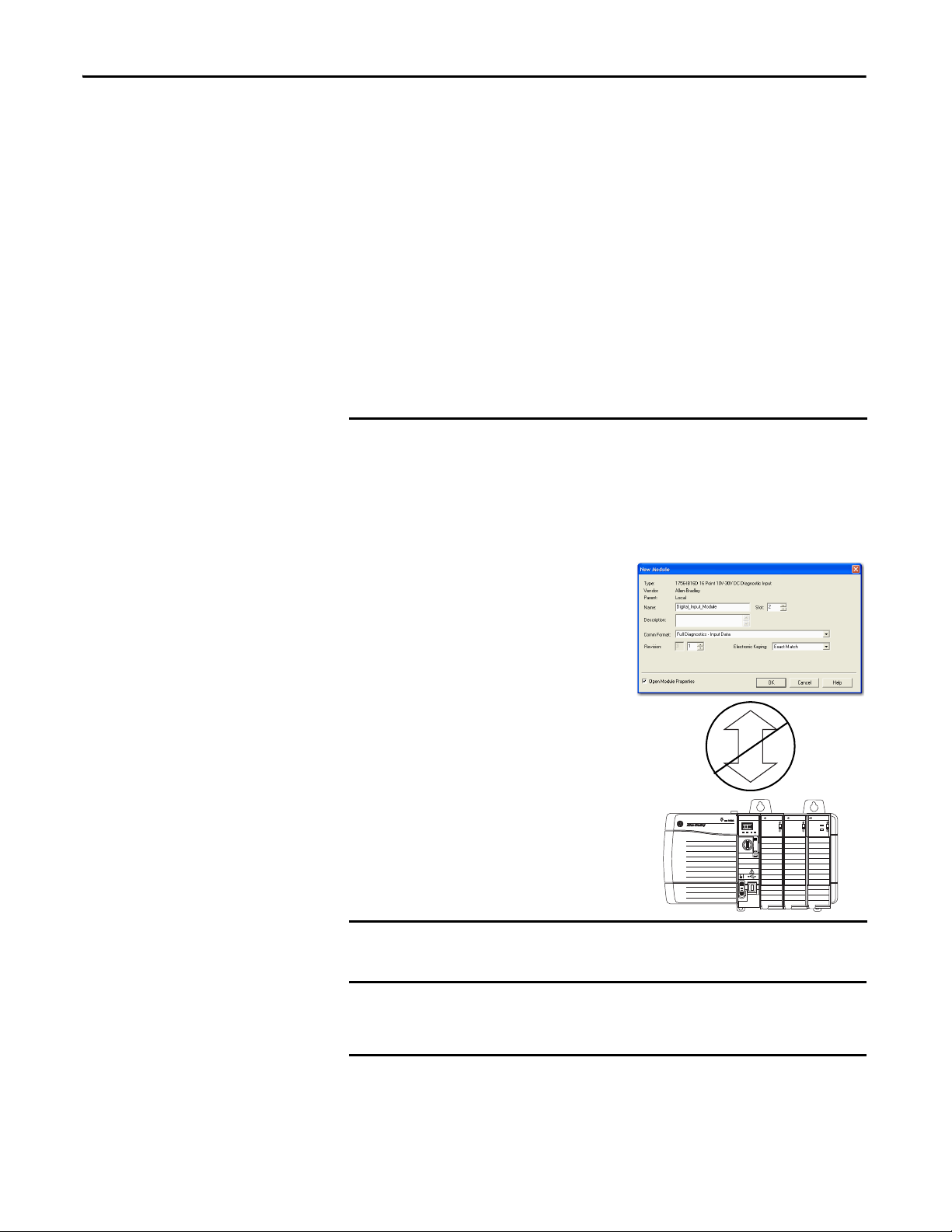
Before You Begin
ControlLogix controllers use isolated analog I/O modules to control devices in a
ControlLogix control system. The modules are installed in a ControlLogix
chassis and use a removable terminal block (RTB) or a Bulletin 1492 interface
(1)
module
cable to connect to field-side wiring.
The modules use the producer/consumer network communication model. This
communication is an intelligent data exchange between modules and other
system devices in which each module produces data without first being polled.
Before you install and use your module, complete the following tasks:
(2)
• Install and ground a 1756 ControlLogix chassis and power supply
. You
can use a standard power supply or a redundant power supply.
For more information on installing 1756 ControlLogix chassis and power
supplies, see Additional Resources on page 8
.
(1) The ControlLogix system has been agency certified using only the ControlLogix RTBs (catalog numbers 1756-TBCH, 1756-TBNH,
1756-TBSH and 1756-TBS6H). Any application that requires agency certification of the ControlLogix system using other wiring
termination methods can require application specific approval by the cert ifying agency.
(2) In addition to standard ControlLogix power supplies, ControlLogix Redundant Power Supplies are also available for your application.
For more information on these supplies, see the ControlLogix Selection Guide, publication 1756-SG001
distributor or Rockwell Automation representative.
Rockwell Automation Publication 1756-UM540A-EN-P - May 2014 9
, or contact your local
Page 10
Chapter 1 Isolated Analog I/O Module Operation in the ControlLogix System
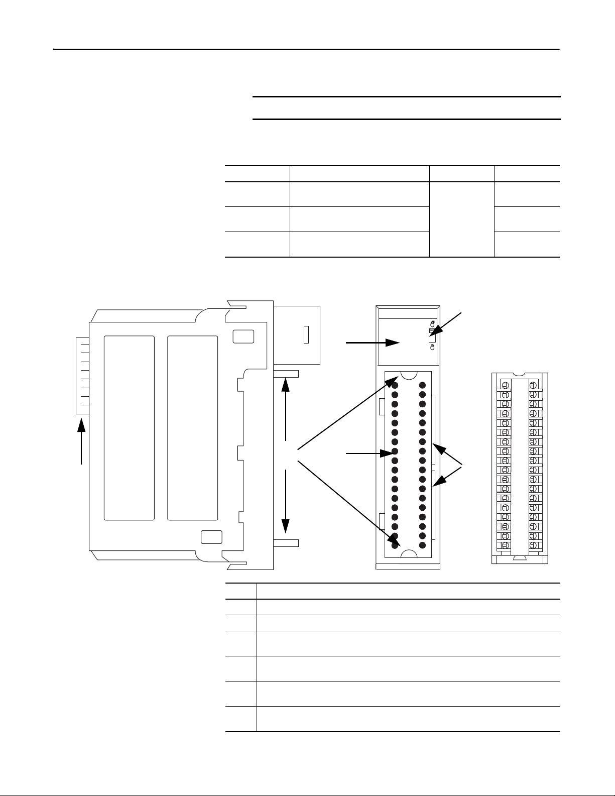
IMPORTANT
1
2
3
4
6
5
Removable Terminal Block
• Verify that you have an RTB or IFM and its components.
Table 1 - Types of ControlLogix Isolated Analog I/O Modules
Cat. No. Description RTB Used Page
1756-IF8I 8-point general purpose isolated analog
1756-IRT8I 8-point isolated combined temperature and mV
1756-OF8I 8-point general purpose isolated analog
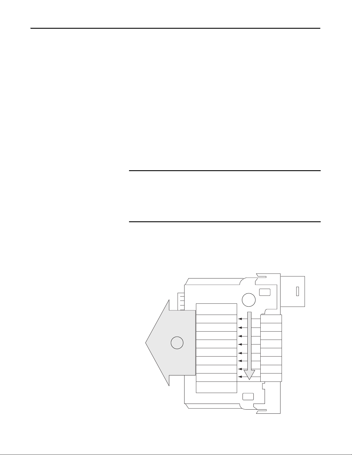
Figure 1 - Parts Illustration of the ControlLogix Isolated Analog I/O Module
RTBs and IFMs are not included with your module purchase.
current/voltage input module
sensing input module
current/voltage output module
36-pin
(1756-TBCH or
1756-TBS6H)
45
65
93
Item Description
1 Backplane connector - Interface for the ControlLogix system that connects the module to the backplane.
2 Top and bottom guides - Guides provide assistance in seating the RTB or IFM cable onto the module.
3 Status indicators - Indicators display the status of communication, module health, and input/output
4 Connectors pins - Input/output, power, and grounding connections are made to the module through
5 Locking tab - The locking tab anchors the RTB or IFM cable on the module, maintaining wiring
6 Slots for keying - Mechanically keys the RTB to prevent inadvertently making the wrong wire connections
10 Rockwell Automation Publication 1756-UM540A-EN-P - May 2014
devices. Indicators help in troubleshooting anomalies.
these pins with the use of an RTB or IFM.
connections.
to your module.
Page 11
Isolated Analog I/O Module Operation in the ControlLogix System Chapter 1
OKFORCE SDRUN
Logix5575
R
U
N
R
E
M
P
R
O
G
ANALOG INPUT
ST
FLT
O
K
ST
FLT
O
K
ANALOG OUTPUT
Controller I/O Modules
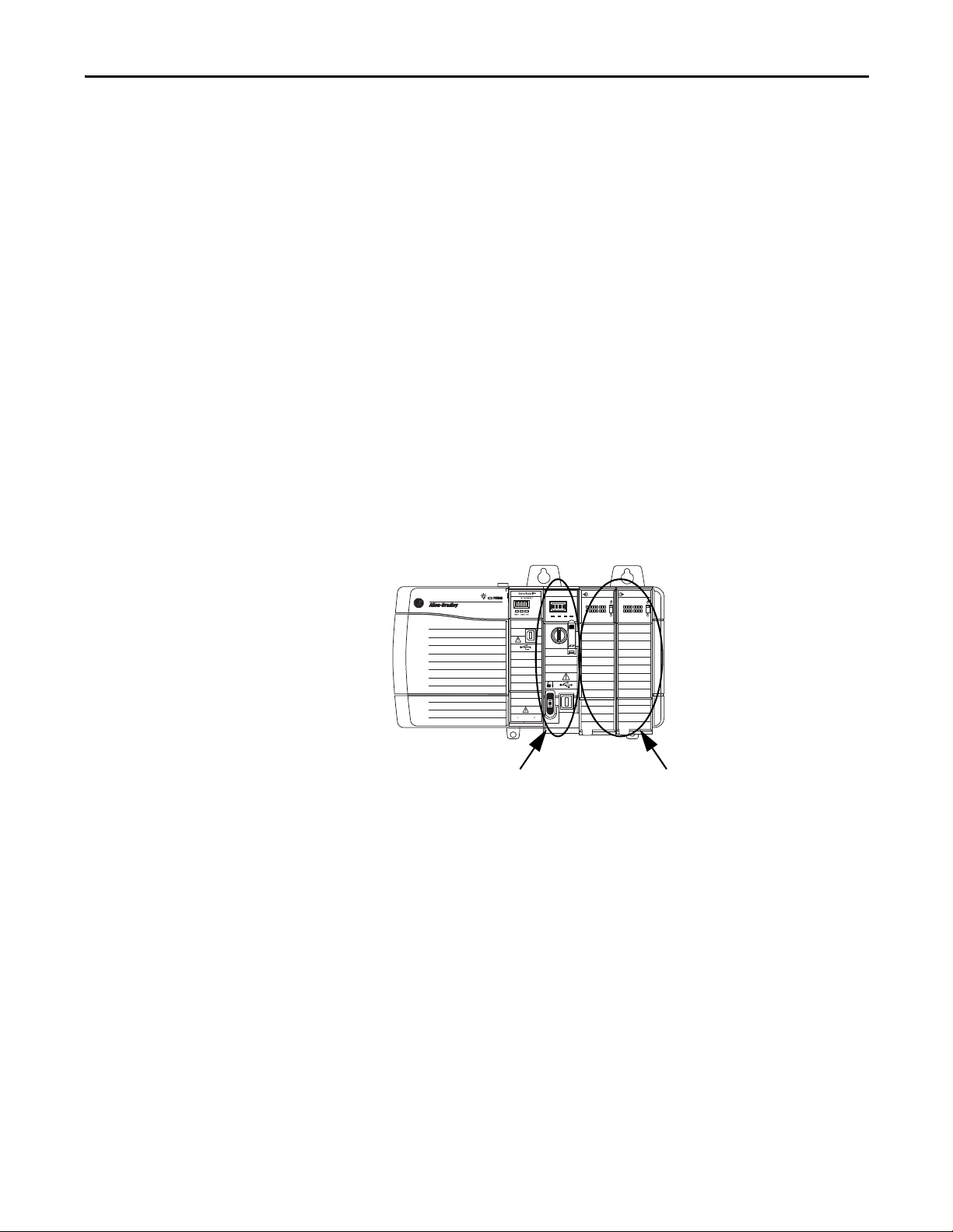
Ownership
Configure a Module
Every I/O module in the ControlLogix system must be owned by a ControlLogix
controller. This controller performs the following:
• Stores configuration data for every module that it owns.
• Resides in the local or remote chassis in regard to the I/O
module’s position.
• Sends the I/O module configuration data to define the module’s behavior
and begin operation in the control system.
Each ControlLogix I/O module must continuously maintain communication
with its owner to operate normally. Typically, each module in the system has only
one owner. Input modules can have more than one owner. Output modules,
however, are limited to a single owner.
You use the I/O configuration portion of the Logix Designer application to
configure each I/O module. An I/O module can reside in either of the following:
•Local chassis - The chassis in which the owner-controller resides.
Rockwell Automation Publication 1756-UM540A-EN-P - May 2014 11
Page 12
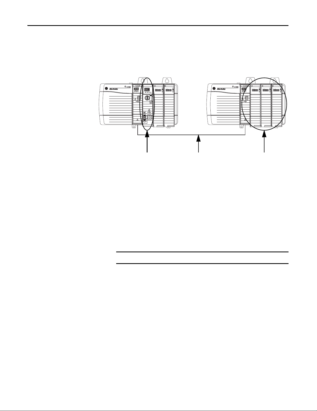
Chapter 1 Isolated Analog I/O Module Operation in the ControlLogix System
OKFORCE SDRUN
Logix5575
R
U
N
R
E
M
P
R
O
G
ANALOG INPUT
ST
FLT
O
K
ST
FLT
O
K
ANALOG OUTPUT
ANALOG INPUT
ST
FLT
O
K
ST
FLT
O
K
ANALOG OUTPUT
ANALOG INPUT
ST
FLT
O
K
Control ler I/O Modules
Local Chassis Remote Chassis
EtherNet/IP Network
IMPORTANT
•Remote chassis - A chassis that does not contain the module’s ownercontroller but is connected to the local chassis over the EtherNet/IP
network or ControlNet network.
Direct Connections
The Logix Designer application transfers configuration data to the controller
during the program download. Subsequently, data is transferred to the I/O
modules in the local and remote chassis.
The I/O module can operate immediately after the project download from the
owner-controller is complete.
A direct connection is a real-time data transfer link between the controller and
the device that occupies the slot that the configuration references.
ControlLogix isolated analog I/O modules support only direct connections
When you download module configuration to a controller, the controller
attempts to establish a direct connection to each module referenced by the
configuration.
12 Rockwell Automation Publication 1756-UM540A-EN-P - May 2014
Page 13

Isolated Analog I/O Module Operation in the ControlLogix System Chapter 1
If controller configuration refers to a chassis slot in the system, the controller
periodically checks for the presence of a device there. If a device is detected, the
controller sends the configuration, and one of the following occurs:
• If the configuration is appropriate to the module detected, a connection is
made and operation begins.
• If the configuration is not appropriate to the module detected, the data is
rejected and the Logix Designer application indicates that an error
occurred.
The configuration can be inappropriate for any of a number of reasons. For
example, a module’s configuration can include a mismatch in electronic
keying that prevents normal operation.
The controller maintains and monitors its connection with a module. Any break
in the connection, for example, the removal of the module from the chassis while
under power, causes a fault.
The Logix Designer application indicates that the fault occurred in the fault
status bits associated with the module. The Logix Designer application monitors
the fault status bits to annunciate the module’s failures.
Rockwell Automation Publication 1756-UM540A-EN-P - May 2014 13
Page 14
Chapter 1 Isolated Analog I/O Module Operation in the ControlLogix System
IMPORTANT
On-Board Memory
Status Data
Channel Data
Channel Data
Channel Data
Channel Data
Channel Data
Channel Data
Ch 0
Ch 1
Ch 2
Ch 3
Ch 4
Ch 5
Timestamp
1
2
Channel Data
Channel Data Ch 6
Ch 7
Input Module Operation
In traditional I/O systems, controllers periodically poll input modules to obtain
their input status.
In the ControlLogix system, the controller does not poll the isolated analog input
modules. Instead, the modules broadcast their input data, that is, channel and
status data, to their backplane periodically.
Requested Packet Interval (RPI)
The RPI is a configurable parameter that defines a specific period of time at
which the module broadcasts input data to the backplane. Valid RPI values are
1…750 ms. The default value is 100 ms.
You set the RPI value at initial module configuration and adjust it as necessary
only when the controller is in Program mode.
Other ControlLogix analog input modules offer the Real Time Sample (RTS)
parameter that determines when channel data is scanned and stored on the
module’s on-board memory until broadcast to the chassis backplane.
The 1756-IF8I and 1756-IRT8I modules do not offer the RTS parameter.
With these modules, the channel sampling rate is exclusively determined by
the RPI value.
At the RPI, the following events occur.
1. The module scans its channels for input data.
2. The module broadcasts the data to its backplane.
14 Rockwell Automation Publication 1756-UM540A-EN-P - May 2014
Page 15

Isolated Analog I/O Module Operation in the ControlLogix System Chapter 1
The input module broadcasts data to the chassis backplane immediately after
the scan:
• When the module resides in the local chassis, the controller receives the
data immediately.
• When the module resides in a remote chassis, the time elapsed before the
controller receives it depends on the configuration of the network
connecting the local and remote chassis.
For more information, see Input Modules in a Remote Chassis
.
Input Modules in a Local Chassis
When an input module resides in a local chassis, as shown on page 11, after the
input module broadcasts data to the chassis backplane, the controller receives
it immediately.
Input Modules in a Remote Chassis
When an input module resides in a remote chassis, as shown on page 12, it is
considered remote input module.
At the RPI, the following events occur.
1. The remote input module scans its channels for input data.
2. The remote input module broadcasts the data to its backplane.
3. The network communication module in the chassis with the I/O module
sends the data over the network to the controller.
Broadcast Method
The isolated analog input module broadcasts data by using one of the following
connection methods:
• Multicast - Data is sent to all network devices
• Unicast - Data is sent to a specific controller depending on the
module’s configuration
For more information on guidelines for specifying RPI rates, see the Logix5000
Controllers Design Considerations Reference Manual, publication
1756-RM094
Rockwell Automation Publication 1756-UM540A-EN-P - May 2014 15
.
Page 16
Chapter 1 Isolated Analog I/O Module Operation in the ControlLogix System
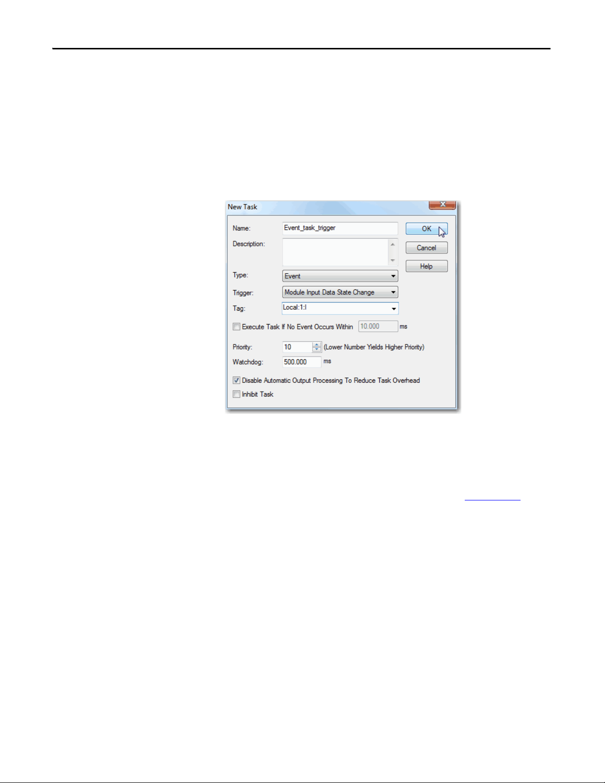
Triggering Event Tasks
ControlLogix isolated analog input modules can trigger an Event task. The Event
task causes the controller to execute a section of logic immediately when a
triggering event occurs. You can configure the Event task to be triggered if new
input data is sent at the RPI.
The following graphic shows an Event task dialog box in Logix Designer
application.
Event tasks are useful for synchronizing process variable (PV) samples and
proportional integral derivative (PID) calculations.
For more information on Event tasks, see the Logix5000 Controllers Tasks,
Programs, and Routines Programming Manual, publication 1756-PM005
.
16 Rockwell Automation Publication 1756-UM540A-EN-P - May 2014
Page 17

Isolated Analog I/O Module Operation in the ControlLogix System Chapter 1
Output Module Operation
The RPI defines when a controller sends data to the isolated analog output
module and when the output module echoes data. The controller sends data to
an output module only at the RPI.
When an output module receives new data from the controller, the module
multicasts or ‘echoes’ a data value that corresponds to the signal present at its
terminals to the rest of the control system. This feature, called Data Echo
whether the output module resides in the local or remote chassis.
Depending on the value of the RPI, with respect to the length of the controller
program scan, the output module can receive and ‘echo’ data multiple times
during one program scan.
When the RPI is less than the program scan length, the module’s output channels
can change values multiple times during a single program scan. The controller
does not depend on reaching the end of the program to send data.
, occurs
Output Modules in a Local Chassis
When an output module resides in a local chassis, as shown on page 11, it receives
data almost immediately after the owner-controller sends it.
Output Modules in a Remote Chassis
When an output module resides in a remote chassis, as shown on page 12, and is
connected to the local chassis via an EtherNet/IP network, the following events
occur for the controller to send data to the output module.
1. The controller broadcasts data to its local chassis at one of the
following events:
• RPI value
• A programmed Immediate Output (IOT) instruction is executed.
An IOT sends data immediately and resets the RPI timer.
2. The 1756 ControlLogix EtherNet/IP communication module in the local
chassis broadcasts the data over the EtherNet/IP network.
3. After receiving the output data, the 1756 ControlLogix EtherNet/IP
communication in the remote chassis broadcasts the data to its backplane,
that is, the remote chassis.
4. The output module receives the data almost immediately after it is
broadcast to the remote chassis backplane.
Rockwell Automation Publication 1756-UM540A-EN-P - May 2014 17
Page 18

Chapter 1 Isolated Analog I/O Module Operation in the ControlLogix System
IMPORTANT
Listen-only Mode
Any controller in the system can listen to the data from any I/O module, that is,
input data or ‘echoed’ output data, even if the controller does not own
the module.
During the I/O configuration process, you can specify a ‘Listen-Only’
connection. For more information on Connection options when configuring
your system, see page 125
When you choose a ‘Listen-Only’ connection, the controller and module
establish communication without the controller sending configuration data. In
this instance, another controller owns the I/O module.
.
If any controller uses a ‘Listen-Only’ connection to the module, none of the
other connections over the EtherNet/IP network can use the Unicast option.
The ‘Listen-Only’ controller receives multicast data from the I/O module as
long as a connection between a controller and I/O module is maintained
If the connection between all owner-controllers and the module is broken,
the module stops multicasting data and connections to all ‘Listening
controllers’ are also broken.
18 Rockwell Automation Publication 1756-UM540A-EN-P - May 2014
Page 19

ControlLogix Isolated Analog I/O
Module Features
Top ic Pa ge
Common Analog I/O Features 20
Relationship between Module Resolution and Scaling 35
Calibrati on 38
Calibrated Accuracy 38
Error Calculated over Hardware Range 39
RTD and Thermocouple Error Calculations 39
Thermocouple Resolution 43
Chapter 2
ControlLogix isolated analog input modules convert an analog signal to a digital
value. The following are example analog signal types to which input modules
convert to digital values:
• Vo l t s
• Millivolts
• Milliamps
• Ohms
ControlLogix isolated analog output modules convert a digital value to an analog
signal. The following are example analog signal types to which output modules
convert digital values:
• Vo l t s
• Milliamps
Rockwell Automation Publication 1756-UM540A-EN-P - May 2014 19
Page 20

Chapter 2 ControlLogix Isolated Analog I/O Module Features
Common Analog I/O Features
The ControlLogix isolated analog I/O modules have the following features:
• CIP Sync Timestamp of Data
• Rolling Timestamp of Data
• Floating Point Data Format
• Module Resolution
• Calibration
• Fault and Status Reporting
• Configurable Software
• Latching of Alarms
• Module Inhibiting
• Electronic Keying
CIP Sync Timestamp of Data
The control system uses a 64-bit system clock. The modules support CIP Sync
timestamping by using the 1588 protocol passed throughout the system. The
1588 protocol is defined in the IEEE 1588-2002 standard, publication Standard
for a Precision Clock Synchronization Protocol for Networked Measurement
and Control Systems.
Each input channel scan or new output application is stamped with a CIP Sync
timestamp and a single timestamp is returned to the controller for the module
with the input data transfer.
You can use this feature for the following:
• To identify the sequence of events in fault conditions or during normal
operation.
It is possible to use the system clock between multiple modules in the same
chassis or throughout a system in which a common Time Master is used.
• To measure the change between samples–which likely correlates closely
with the RPI if no samples are missed in the logic–and to detect when a
new sample is available for processing via the logic.
You can also use the 1588 Protocol to synchronize sampling for modules across
the entire system. By using the Synchronized Sampling feature, described in detail
on page 57
input samples precisely with each other when using the same RPI.
and page 81, you can configure multiple modules to coordinate their
20 Rockwell Automation Publication 1756-UM540A-EN-P - May 2014
Page 21

ControlLogix Isolated Analog I/O Module Features Chapter 2
Synchronized Sampling lets you configure a test stand, for example, and take
many measurements simultaneously across many modules, if needed, while still
precisely coordinating the sampling. With these modules, the synchronized
sampling should coordinate within approximately ± 20 μs.
Rolling Timestamp of Data
The rolling timestamp is a continuously running 16-bit rolling timestamp that
counts in milliseconds from 0…32,767 ms; where 1 ms = 1 count.
Rolling Timestamp with the 1756-IF8I and 1756-IRT8I Modules
The 1756-IF8I and 1756-IRT8I modules scan their inputs at the RPI, update the
input data, and update the rolling timestamp value. Other ControlLogix analog
input modules scan their inputs at the RTS, not the RPI.
In either case, though, the controller program uses the last two rolling timestamp
values to calculate the interval between the receipt of data or the time at which
new data is received.
The rolling value is commonly used with instructions such as the PID and PIDE
instructions. Every time a rolling timestamp changes, a PID or PIDE instruction
is executed. When you configure a PID instruction for use with a 1756-IF8I and
1756-IRT8I module, set the loop update time equal to the module’s RPI value.
Rolling Timestamp with the 1756-OF8I Module
For the 1756-OF8I module, the rolling timestamp value is updated only when
new values are applied to the Digital to Analog Converter (DAC).
Rockwell Automation Publication 1756-UM540A-EN-P - May 2014 21
Page 22

Chapter 2 ControlLogix Isolated Analog I/O Module Features
EXAMPLE
Floating Point Data Format
The modules return channel data to the owner-controller in the IEEE 32-bit
floating point data format. In your Logix Designer application, the data type is
REAL. You can configure the module to scan its channels and return data as
quickly as every 1 ms.
The floating point data format lets you change the data representation of the
selected channel. Although the full range of the module does not change, you can
scale your module to represent I/O data in specific terms for your application.
When you scale a channel, you select two points that represent signal units, that
is, a Low Signal and a High Signal. You also select two points that represent
engineering units, that is, Low Engineering and High Engineering.
The Low Signal point equates to the Low Engineering point and the High Signal
point matches the High Engineering point.
A 1756-IF8I module used in current mode maintains 0…21 mA range
capability. Your application uses a 4…20 mA transmitter.
• If you want to receive values in signal units, configure the module
as follows:
– Low Signal = 4 mA
– High Signal = 20 mA
– Low Engineering = 4 EU
– High Engineering = 20 EU
• If you want to receive values in terms of Percent of Full Scale, configure
the module as follows:
– Low Signal = 0 mA
– High Signal = 20 mA
– Low Engineering = 0%
– High Engineering = 100%
By default, module channels used in Current mode are scaled such at 4…20 mA
equate to 0…100% engineering units. Other module channels scale 1:1 with
respect to signal units and engineering units by default.
Module Resolution
The modules support the following resolutions:
• 1756-IF8I and 1756-IRT8I modules – 24-bit resolution
• 1756-OF8I module – 16-bit resolution
For more information on module resolution, see page 35
.
22 Rockwell Automation Publication 1756-UM540A-EN-P - May 2014
Page 23

ControlLogix Isolated Analog I/O Module Features Chapter 2
Module Quality Reporting
The modules indicate the quality of channel data returned to the ownercontroller. Data quality represents accuracy. There are levels of data quality
reported via module input tags.
The following input tags indicate the level of data quality. In the tag names, x
represents the module channel number:
• I.Ch[x].Fault tag - This tag indicates that channel data can be completely
inaccurate and cannot be trusted for use in the application. If the tag is set
to 1, you cannot trust the data reported. You must troubleshoot the
module to correct the cause of the inaccuracy.
Common causes of inaccurate data include the following:
– An overrange or underrange condition exists.
– A wire off detection condition has occurred.
– A short circuit detection condition has occurred.
• I.Ch[x].Uncertain tag - This tag indicates that channel data can be
inaccurate but it is not known to what degree of inaccuracy. We
recommend that you do not use the data for control.
If the tag is set to 1, you know the data can be inaccurate but you must
troubleshoot the module to discover what degree of inaccuracy exists.
Common causes of uncertain data include the following:
– The channel is actively being calibrated.
– An invalid sensor offset value exists.
– The channel’s last data sample failed CRC while the most recent data
sample was valid and used.
We recommend that you monitor these tags in your program to make sure the
application is operating as expected with accurate channel input data.
Rockwell Automation Publication 1756-UM540A-EN-P - May 2014 23
Page 24

Chapter 2 ControlLogix Isolated Analog I/O Module Features
Calibration
These modules use precise analog components that maintain their specifications
over time. The modules are calibrated at the factory and recalibration is not
required.
If desired, you can recalibrate the modules on a channel-by-channel or modulewide basis. For more information, see Calibrated Accuracy on page 38
choose to recalibrate the modules in the future.
if you
Fault and Status Reporting
The modules provide fault and status data along with channel data. Faults are
indicated via the status indicators on the front of the module as well as the
module tags. Status data is available via the module tags.
• For more information on fault and status reporting via module tags, see the
following:
– 1756-IF8I fault and status reporting - page 64
– 1756-IRT8I fault and status reporting - page 92
– 1756-OF8I fault and status reporting - page 102
• For more information on fault reporting via status indicators, see
Chapter 2, Troubleshoot Your Module on page 157
24 Rockwell Automation Publication 1756-UM540A-EN-P - May 2014
Page 25

ControlLogix Isolated Analog I/O Module Features Chapter 2
IMPORTANT
Configurable Software
Use one of the following software applications with your module:
• RSLogix 5000 software, versions 18…20
• Logix Designer application, version 21 or later
You must install Add-on Profiles (AOP) to use the modules in any Logix
Designer application or RSLogix 5000 software project.
This publication describes configuration with Logix Designer
application. AOPs are available at:
https://download.rockwellautomation.com/esd/
download.aspx?downloadid=addonprofiles
All module feature configuration begins in the I/O configuration portion of the
Logix Designer application. In addition to enable or disable module features, you
can use the application to interrogate any module for the following
module information:
• Serial number
• Revision information
• Catalog number
• Vendor identification
• Error/fault information
• Diagnostic counters
For more information on configurable software and its use, see the
following sections:
• Preface
• Chapter 7, Configure ControlLogix Isolated Analog I/O Modules
• Chapter 8, Calibrate the ControlLogix Isolated Analog I/O Modules
• Chapter 9, Troubleshoot Your Module
Rockwell Automation Publication 1756-UM540A-EN-P - May 2014 25
Page 26

Chapter 2 ControlLogix Isolated Analog I/O Module Features
IMPORTANT
IMPORTANT
Latching of Alarms
This feature latches a module alarm in the set position once the alarm is triggered.
The alarm remains on, even if the condition causing it to occur disappears, until
the alarm is unlatched.
You must manually unlatch the alarm. You can unlatch the alarm, by using one
of the following methods:
• While the project is online, click the Alarm Configuration tab on the
Module. Then click Unlatch to unlatch a specific alarm or Unlatch All to
unlatch all alarms.
• Change the module output tag for the alarm that you want to unlatch. For
example, the Ch[x].LLAlarmUnlatch tag to unlatch a Low Low Alarm.
For more information on module tags, see Appendix A, Isolated Analog I/O
Module Tag Definitions on page 173.
• Use a CIP Generic message.
For more information how to use a CIP Generic message, see Rockwell
Automation Knowledgebase article #63046, How to Reset Latched Status
of an Analog Module. You can access the article at: (Login required)
https://rockwellautomation.custhelp.com/
To see where to latch alarms, see page 131
and page 133.
Module Inhibiting
This feature suspends the connection between an owner-controller and a
module. This process can occur in either of the following ways:
• You write configuration for an I/O module but inhibit the module to
prevent it from communicating with the owner-controller.
In this case, the owner does not establish a connection and configuration is
not sent to the module until the connection is uninhibited.
• A controller owns a module and has downloaded configuration to it. Data
is currently being exchanged over the connection between the devices.
In this case, when you inhibit the module and the owner-controller
behaves as if the connection to the module does not exist.
Whenever you inhibit an output module, it enters Program mode and all
outputs change to the state configured for the Program mode. For example,
if an output module is configured so that the state of the outputs go to zero
(0) during Program mode, whenever that module is inhibited, the outputs
go to zero (0).
26 Rockwell Automation Publication 1756-UM540A-EN-P - May 2014
Page 27

ControlLogix Isolated Analog I/O Module Features Chapter 2
The following examples are instances where you need to use module inhibiting:
• Multiple controllers own an analog input module. A configuration change
is required. You must make the change in the program in all controllers.
In this case, complete the following tasks.
a. Inhibit the module.
b. Change configuration in all controllers.
c. Uninhibit the module.
• You want to upgrade the module. We recommend you complete the
following tasks.
a. Inhibit the module.
b. Perform the upgrade.
c. Uninhibit the module.
• The program includes a module that you do not physically possess and you
do not want the controller to continually look for a module that does not
exist.
Inhibit the module until it physically resides in the proper slot.
To see where to inhibit a module connection, see page 126
.
Rockwell Automation Publication 1756-UM540A-EN-P - May 2014 27
Page 28

Chapter 2 ControlLogix Isolated Analog I/O Module Features
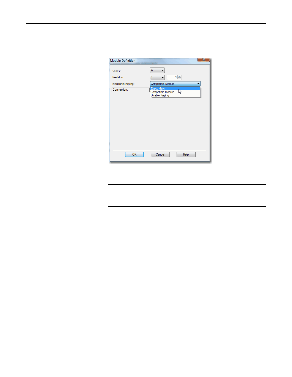
Electronic Keying
The electronic keying feature automatically compares the expected module, as
shown in the I/O Configuration tree, to the physical module before I/O
communication begins. You can use electronic keying to help prevent
communication to a module that does not match the type and revision expected.
For each module in the I/O Configuration tree, the user-selected keying option
determines if, and how, an electronic keying check is performed. Typically, three
keying options are available:
• Exact Match
• Compatible Keying
• Disable Keying
You must carefully consider the benefits and implications of each keying option
when selecting between them. For some specific module types, fewer options are
available.
Electronic keying is based on a set of attributes unique to each product revision.
When a Logix5000 controller begins communicating with a module, this set of
keying attributes is considered.
Attribute Description
Vendor The manufacturer of the module, for example, Rockwell Automation/Allen-Bradley.
Product Type The general type of the module, for example, communication adapter, AC drive, or digital
Product Code The specific type of module, generally represented by its catalog number, for example,
Major Revision A number that represents the functional capabilities and data exchange formats of the
Minor Revision A number that indicates the module’s specific firmware revision. Minor Revisions
I/O.
1756-IRT8I.
module. Typically, although not always, a later, that is higher, Major Revision supports at
least all of the data formats supported by an earlier, that is lower, Major Revision of the
same catalog number and, possibly, additional ones.
typically do not impact data compatibility but can indicate performance or behavior
improvement.
28 Rockwell Automation Publication 1756-UM540A-EN-P - May 2014
Page 29
ControlLogix Isolated Analog I/O Module Features Chapter 2
IMPORTANT
You can find revision information on the Module Definition dialog box.
Figure 2 - Module Definition Dialog Box
Changing electronic keying selections online can cause the I/O
communication connection to the module to be disrupted and can result in
a loss of data.
Rockwell Automation Publication 1756-UM540A-EN-P - May 2014 29
Page 30
Chapter 2 ControlLogix Isolated Analog I/O Module Features
EXAMPLE
IMPORTANT
Module Configuration
Vendor = Allen-Bradley
Product Type = Digital Input Module
Catalog Number = 1756-IB16D
Major Revision = 3
Minor Revision = 1
Physical Module
Vendor = Allen-Bradley
Product Type = Digital Input Module
Catalog Number = 1756-IB16D
Major Revision = 3
Minor Revision = 2
Communication is prevented
Exact Match
Exact Match Keying requires all keying attributes, that is, Vendor, Product Type,
Product Code (catalog number), Major Revision, and Minor Revision, of the
physical module and the module created in the software to match precisely to
establish communication. If any attribute does not match precisely, I/O
communication is not permitted with the module or with modules connected
through it, as in the case of a communication module.
Use Exact Match keying when you need the system to verify that the module
revisions in use are exactly as specified in the project, such as for use in highlyregulated industries. Exact Match keying is also necessary to enable Automatic
Firmware Update for the module via the Firmware Supervisor feature from a
Logix5000 controller.
In the following scenario, Exact Match keying prevents I/O
communication:
The module configuration is for a 1756-IB16D module with module revision
3.1. The physical module is a 1756-IB16D module with module revision 3.2.
In this case, communication is prevented because the Minor Revision of the
module does not match precisely.
30 Rockwell Automation Publication 1756-UM540A-EN-P - May 2014
Logix5575
ST01234567
FLT0 12 3 4 5 6 7
ST 89 10 111213 1415
FLT89101112131415
OKFORCE SDRUN
M
E
R
P
N
R
O
U
G
R
ANALOG INPUT
DC INPUT
DC INPUT
CAL
ST0 1 2 34 5 6 7
O
O
K
K
ST 89 1011 121314 15
OK
DIAGNOSTIC
Changing electronic keying selections online can cause the I/O
Communication connection to the module to be disrupted and can result in
a loss of data.
Page 31

ControlLogix Isolated Analog I/O Module Features Chapter 2
EXAMPLE
Module Configuration
Vendor = Allen-Bradley
Product Type = Digital Input Module
Catalog Number = 1756-IB16D
Major Revision = 3
Minor Revision = 3
Physical Module
Vendor = Allen-Bradley
Product Type = Digital Input Module
Catalog Number = 1756-IB16D
Major Revision = 3
Minor Revision = 2
Communication is prevented
ANALOG INPUT
ST0 1 2 34 5 6 7
ST 89 1011 121314 15
O
K
CAL
OK
OKFORCE SDRUN
Logix5575
R
U
N
R
E
M
P
R
O
G
DC INPUT
DC INPUT
FLT89101112131415
ST01234567
ST 89 10 111213 1415
O
K
FLT0 12 3 4 5 6 7
DIAGNOSTIC
Compatible Keying
Compatible Keying indicates that the module determines whether to accept or
reject communication. Different module families, communication adapters, and
module types implement the compatibility check differently based on the family
capabilities and on prior knowledge of compatible products.
Compatible keying is the default setting. Compatible keying lets the physical
module accept the key of the module configured in the software, provided that
the configured module is one the physical module is capable of emulating. The
exact level of emulation required is product and revision specific.
With Compatible keying, you can replace a module of a certain Major Revision
with one of the same catalog number and the same or later, that is higher, Major
Revision. In some cases, the selection makes it possible to use a replacement that
is a different catalog number than the original. For example, you can replace a
1756-CNBR module with a 1756-CN2R module.
Release notes for individual modules indicate the specific compatibility details.
When a module is created, the module developers consider the module’s
development history to implement capabilities that emulate those of the previous
module. However, the developers cannot know future developments. Because of
this, when a system is configured, we recommend that you configure your module
by using the earliest, that is, lowest, revision of the physical module that you
believe will be used in the system. By doing this, you can avoid the case of a
physical module rejecting the keying request because it is an earlier revision than
the one configured in the software.
In the following scenario, Compatible keying prevents I/O communication:
The module configuration is for a 1756-IB16D module with module revision
3.3. The physical module is a 1756-IB16D module with module revision 3.2. In
this case, communication is prevented because the minor revision of the
module is lower than expected and.cant be incompatible with 3.3.
Rockwell Automation Publication 1756-UM540A-EN-P - May 2014 31
Page 32

Chapter 2 ControlLogix Isolated Analog I/O Module Features
EXAMPLE
IMPORTANT
Module Configuration
Vendor = Allen-Bradley
Product Type = Digital Input Module
Catalog Number = 1756-IB16D
Major Revision = 2
Minor Revision = 1
Physical Module
Vendor = Allen-Bradley
Product Type = Digital Input Module
Catalog Number = 1756-IB16D
Major Revision = 3
Minor Revision = 2
Communication is allowed
In the following scenario, Compatible keying lets I/O
communication occur:
The module configuration is for a 1756-IB16D module with module revision
2.1. The physical module is a 1756-IB16D module with module revision 3.2.
In this case, communication is allowed because the major revision of the
physical module is higher than expected and the module determines that it
is compatible with the prior major revision.
Logix5575
ST01234567
FLT0 12 3 4 5 6 7
ST 89 10 111213 1415
FLT89101112131415
OKFORCE SDRUN
M
E
R
P
N
R
O
U
G
R
ANALOG INPUT
DC INPUT
DC INPUT
CAL
ST0 1 2 34 5 6 7
O
O
K
K
ST 89 1011 121314 15
OK
DIAGNOSTIC
Changing electronic keying selections online can cause the I/O
communication connection to the module to be disrupted and can result in
a loss of data.
32 Rockwell Automation Publication 1756-UM540A-EN-P - May 2014
Page 33

ControlLogix Isolated Analog I/O Module Features Chapter 2
EXAMPLE
Module Configuration
Vendor = Allen-Bradley
Product Type = Digital Input Module
Catalog Number = 1756-IA16
Major Revision = 3
Minor Revision = 1
Physical Module
Vendor = Allen-Bradley
Product Type = Analog Input Module
Catalog Number = 1756-IF16
Major Revision = 3
Minor Revision = 2
Communication is prevented
Disabled Keying
Disabled Keying indicates the keying attributes are not considered when
attempting to communicate with a module. Other attributes, such as data size
and format, are considered and must be acceptable before I/O communication is
established. With Disabled keying, I/O communication can occur with a module
other than the type specified in the I/O Configuration tree with unpredictable
results. We generally do not recommend using Disabled keying.
ATTENTION: Be extremely cautious when using Disabled keying; if used
incorrectly, this option can lead to personal injury or death, property
damage, or economic loss.
If you use Disabled keying, you must take full responsibility for understanding
whether the module being used can fulfill the functional requirements of the
application.
In the following scenario, Disable keying prevents I/O
communication:
The module configuration is for a 1756-IA16 digital input module. The
physical module is a 1756-IF16 analog input module. In this case,
communication is prevented because the analog module rejects the data
formats that the digital module configuration requests.
Logix5575
ST01234567
FLT0 12 3 4 5 6 7
ST 89 10 111213 1415
FLT89101112131415
OKFORCE SDRUN
M
E
R
P
N
R
O
U
G
R
ANALOG INPUT
DC INPUT
DC INPUT
CAL
ST0 1 2 34 5 6 7
O
O
K
K
ST 89 1011 121314 15
OK
DIAGNOSTIC
Rockwell Automation Publication 1756-UM540A-EN-P - May 2014 33
Page 34

Chapter 2 ControlLogix Isolated Analog I/O Module Features
EXAMPLE
IMPORTANT
Module Configuration
Vendor = Allen-Bradley
Product Type = Digital Input Module
Catalog Number = 1756-IA16
Major Revision = 2
Minor Revision = 1
Physical Module
Vendor = Allen-Bradley
Product Type = Digital Input Module
Catalog Number = 1756-IB16
Major Revision = 3
Minor Revision = 2
Communication is allowed
In the following scenario, Disable keying lets I/O
communication occur:
The module configuration is for a 1756-IA16 digital input module. The
physical module is a 1756-IB16 digital input module. In this case,
communication is allowed because the two digital modules share common
data formats.
Changing electronic keying selections online can cause the I/O
communication connection to the module to be disrupted and can result in
a loss of data.
To see where to configure Electronic Keying, see page 126.
Logix5575
ST01234567
FLT0 12 3 4 5 6 7
ST 89 10 111213 1415
FLT89101112131415
OKFORCE SDRUN
M
E
R
P
N
R
O
U
G
R
ANALOG INPUT
DC INPUT
DC INPUT
CAL
ST0 1 2 34 5 6 7
O
O
K
K
ST 89 1011 121314 15
OK
DIAGNOSTIC
34 Rockwell Automation Publication 1756-UM540A-EN-P - May 2014
Page 35

ControlLogix Isolated Analog I/O Module Features Chapter 2
Relationship between Module Resolution and Scaling
The following concepts must be explained in conjunction with each other:
• Module Resolution
• Scaling
Module Resolution
Resolution is the smallest degree of change that the module is capable
of detecting. Module resolution represents a fixed number of counts across the
module’s theoretical operating range.
• 1756-IF8I and 1756-IRT8I modules support 24-bit resolution.
The 24 bits represent 16,777,216 counts.
• 1756-OF8I module supports 16-bit resolution.
The 16 bits represent 65,536 counts.
Resolution on Input Modules
The theoretical operating range is the full range across which the module can
operate. For example, a 1756-IF8I module in Current mode has a theoretical
operating range = -25.1…25.1 mA. The 24-bit resolution and 16,777,216 counts
are available across 50.2 mA which yields our calculated 2.99 nA/count
resolution.
However, when the 1756-IF8I module operates in Current mode, it is configured
for an input range = 0…20 mA. This range limits the input to a 0…21 mA actual
range capability.
The number of counts on a module is fixed. Module actual range capabilities,
however, narrow operating ranges from the theoretical and result in supporting
fewer counts. Using the example above, the 0…21 mA actual range capability
represents 5,815,117 counts, that is, slightly more than 22.5 bits.
Divide the actual range capability by the number of counts in that range to
determine the value of each count. The input range you choose during module
configuration determines the value of each count. It does not determine the
number of counts in that range. Therefore, module resolution across the usable
input operating range is not always 24 bits.
Resolution on Output Module
The module resolution for the 1756-OF8I module is always 16 bits, regardless of
operating mode and operating range.
Rockwell Automation Publication 1756-UM540A-EN-P - May 2014 35
Page 36

Chapter 2 ControlLogix Isolated Analog I/O Module Features
IMPORTANT
The following table lists the resolution for each module’s input/output range and
corresponding range capability.
Table 2 - Module Resolution in Various Configuration Selections
Module Mode Available Input/
Vol tag e
1756-IF8I
Curren t
Thermocouple -100…100 mV -101…101 mV
1756-IRT8I
1756-OF8I
(1) These ranges represent the range choices available in the Logix Designer application.
RTD
Vol tag e
Current 0…20 mA 0…21 mA 16.00 0.32 µA
Output Range
-10…10V
0…10V
0…5V
0…20 mA
0…20 mA (sourcing)
1…500 Ω
2…1000 Ω
4…2000 Ω
8…4000 Ω
-10…10V
0…10V
0…5V
(1)
Actual Input/Output
Range Capability
-10.5…10.5V
0…10.5V
0…5.25V
0…21 mA
0…21 mA (sourcing)
0…510 Ω
0…1020 Ω
0…2040 Ω
0…4080 Ω
-10.5…10.5V
0…10.5V
0…5.25V
Because these modules must allow for possible calibration inaccuracies,
resolution values represent the available Analog-to-Digital or Digital-toAnalog counts over the specified range.
Additionally, RPI and Notch Filter settings affect module resolution on the
1756-IF8I and 1756-IRT8I modules. For more information, see page49
page 68
Number of Bits
Across the
Theoretical
Operating Range
24 bits
24 bits
16 bits
, respectively.
Number of Bits
Across the Actual
Range Capability
23.75
22.75
21.75
22.74
23.98 0.01 µV/count
23.98
16.00
Resolution (signal
per count)
1.49 µV/count
2.99 nA/count
0.06 mΩ/count
0.12 mΩ/count
0.25 mΩ/count
0.50 mΩ/count
0.32 mV/count
0.16 mV/count
0.08 mV/count
and
36 Rockwell Automation Publication 1756-UM540A-EN-P - May 2014
Page 37

ControlLogix Isolated Analog I/O Module Features Chapter 2
Module Resolution
5,815,117 counts
0 mA 21 mA
4 mA 20 mA
0% in Engineering
Units
100% in Engineering
Units
Module Scaling
Module scaling represents the data
returned from the module to the controller.
IMPORTANT
Scaling
When scaling, you choose two points along the module’s operating range and
apply low and high values to those points.
For example, if you are using the 1756-IF8I module in Current mode, the module
supports a 0…21 mA actual range capability. But your application uses a 4…20
mA transmitter. Scaling lets you configure the module to return data to the
controller so that a low signal value of 4 mA returns a low engineering value of
0% and a high signal value of 20 mA returns a high engineering value of 100%.
The returned engineering units value is indicated in the I.Ch[x].Data tag as
shown in Ta b l e 3
Figure 3 - Module Resolution Compared to Module Scaling
.
In choosing two points for the low and high value of your application, you
do not limit the range of the module. The module’s range and its resolution
remain constant regardless of how you scale it for your application.
The module can operate with values beyond the 4…20 mA range. If an input
signal beyond the low and high signals is present at the module, for example,
0 mA, that data is represented in terms of the engineering units set during scaling.
The following table shows example values that can appear based on the example
mentioned above.
Table 3 - Current Values Represented in Engineering Units
Current Engineering Units Value Value in I.Ch[x].Data Tag
0.0 mA -25.00% -25.00
4.0 mA 0.0% 0.00
12.0 mA 50.0% 50.0
20.0 mA 100.0% 100.0
21.0 mA 106.25% 106.25
Rockwell Automation Publication 1756-UM540A-EN-P - May 2014 37
Page 38

Chapter 2 ControlLogix Isolated Analog I/O Module Features
Calibration
Calibrated Accuracy
The ControlLogix isolated analog modules are calibrated via the
following methods:
• Factory calibration when the modules are built.
• User-executed calibration as described in Chapter 8
ControlLogix Isolated Analog I/O Modules on page 137.
User-executed calibration is optional.
• 1756-IRT8I module only - Channels configured for Thermocouple
inputs perform a lead resistance self-calibration when the module power
is cycled.
The Calibrated Accuracy specification represents the module’s accuracy when
its ambient temperature is the same as the temperature at which the module
was calibrated.
The following specifications are related to Calibrated Accuracy:
• Calibrated Accuracy at 25 °C (77 °F)
• Module Error over Full Temperature Range
, Calibrate the
Calibrated Accuracy at 25 °C (77 °F)
This specification matches the temperature at which the module was calibrated
in the factory during manufacturing.
The module’s accuracy when operating in 25 °C (77 °F) conditions = 0.05%.
38 Rockwell Automation Publication 1756-UM540A-EN-P - May 2014
Page 39

ControlLogix Isolated Analog I/O Module Features Chapter 2
EXAMPLE
Module Error over Full Temperature Range
The Module Error Over Full Temperature Range specification represents the
error that occurs if the module’s ambient temperature changes a total of 60 °C
(140 °F), that is, from 0…60 °C (32…140 °F) or 60…0 °C (140…32 °F).
The module accuracy over the full temperature range = 0.1%.
Error Calculated over Hardware Range
RTD and Thermocouple Error Calculations
A ControlLogix isolated analog I/O module’s calibration accuracy at 25 °C (77
°F) is calculated over the full hardware range of the module and is not dependent
on the application’s use of the range. The error is the same if you are measuring it
across a 10% or 100% portion of a given range.
However, a module’s accuracy at 25 °C (77 °F) is dependent on the hardware
range in which the module operates.
When the 1756-IRT8I channel uses the Thermocouple (mV) input type, the
input range is -100…100 mV, the module error is 0.2 mV when using 0.1%
of range accuracy.
These error values are the same whether you use 10% or 100% of the
chosen range.
When you use the 1756-IRT8I module in temperature mode, error calculations
are achieved by a two-step process.
1. Calculate the module’s error in ohms or volts.
2. Convert the ohm/volt error to temperature for the specific sensor and at
the correct application temperature.
Rockwell Automation Publication 1756-UM540A-EN-P - May 2014 39
Page 40

Chapter 2 ControlLogix Isolated Analog I/O Module Features
RTD Error
Module error on the 1756-IRT8I module used with an RTD input is defined in
ohms. The error is calculated across the entire input range selected, not the
available range of a sensor used with the module. For example, if the 1…500
input range is used, the module error is calculated across 510
(actual range = 0…510
Ω).
Ω
The error in ohms translates to temperature, but that translation varies because
the relationship is non-linear. The most effective way to check 1756-IRT8I
module error is to calculate the error in ohms and use that value in a linearization
table to check the temperature error.
If the module is calibrated at operating temperature and the operating
temperature remains relatively stable, calibration accuracy is better than 0.05% of
the full range. This 0.05% value is a worst case value. In other words, with the
1…500
Ω input range selected, the worst case module error is 0.255 Ω.
Finally, you must check an RTD linearization table to determine how the
temperature error of 0.510
Ω translates.
Ω
For example, if the 1756-IRT8I has a 0.05% (or 0.255
Ω) error and is at a
temperature of 0 °C (32 °F), the temperature error is ±0.65 °C (±1.17 °F) when
the Platinum 385 sensor type is used. This same error at a temperature of 200 °C
(392 °F) translates to a temperature error of ±0.69 °C (±1.26 °F).
40 Rockwell Automation Publication 1756-UM540A-EN-P - May 2014
Page 41

ControlLogix Isolated Analog I/O Module Features Chapter 2
EXAMPLE
Thermocouple Error
Thermocouple error at 25 °C (77 °F) indicates the module’s accuracy in
measuring temperature. This accuracy varies depending on these factors:
• Input range = -100…100 mV.
• Thermocouple sensor type, any of the following:
– Typ e B
– Typ e C
– Typ e D
– Typ e E
– Typ e J
– Type K (default value)
– Typ e N
– Typ e R
– Typ e S
– Typ e T
– Typ e T XK/ XK ( L)
• Application temperature, that is, the temperature of the physical location
where the thermocouple is being used.
When a 1756-IRT8I module is used with a thermocouple input type in the
following conditions, module error at 25 °C (77 °F) is ±3.74 °:
• Connected to a type S thermocouple
• Application temperature of 1200 °C (2192 °F)
In other words, the difference between the temperature the module
reports and the actual application temperature can be ±3.74 °.
The module can report an application temperature of 1200 ° C (2192 °F) in
this case when the actual temperature can be in the range from
1196.26…1203.74 °C (2185.268…2198.732 °F).
These calculations used a typical error of 0.02% of full scale range.
Rockwell Automation Publication 1756-UM540A-EN-P - May 2014 41
Page 42

Chapter 2 ControlLogix Isolated Analog I/O Module Features
IMPORTANT
Module Error at 25 °C (77
°F)
Ta b l e 4 lists the 1756-IRT8I module error at 25 °C (77 °F) when using a
thermocouple input type.
Table 4 - 1756-IRT8I Module Error At 25 °C (77 °F) with Thermocouple Input Type
Application
Temperature
-200 °C (-328 °F) 1.65 1.79 2.06 2.95 4.53 2.86
0 °C (32 °F) 3.46 4.59 0.93 8.51 8.33 0.77 0.89 1.14 1.72 1.16
200 °C (392 °F) 2.65 2.83 0.71 5.09 5.32 0.61 0.81 1.13 1.36 0.85
400 °C (752 °F) 11.08 2.37 2.36 0.62 4.34 4.70 0.56 0.82 1.07 1.21 0.73
600 °C (1112 °F) 7.56 2.37 2.22 0.56 3.96 4.41 0.56 0.77 1.06 1.16
800 °C (1472 °F) 5.89 2.37 2.20 0.51 3.65 4.14 0.57 0.70 1.10 1.15
1000 °C (1832 °F) 4.93 2.37 2.25 3.40 3.90 0.60 0.76 1.15 1.17
1200 °C (2192 °F) 4.35 2.65 2.36 3.23 3.74 0.79 1.23 1.21
1400 °C (2552 °F) 3.99 2.81 2.47 3.18 3.71 1.33
1600 °C (2912 °F) 3.85 3.00 2.63 3.24 3.80
1800 °C (3272 °F) 3.92 3.46 2.85 3.67 4.36
2000 °C (3632 °F) 3.75 3.19
2200 °C (3992 °F) 4.09 3.95
Module Error at 25 °C (77 °F) When Connected to Thermocouple Types
Type B Type C Type D Type TXK/
XK(L)
Type R Type S Type E Type J Type K Type N Type T
When calculating total measurement error, module error at 25 °C (77 °F) is only
one factor in deriving the total measurement error budget.
Other factors that impact thermocouple measurement error include
the following:
• Thermocouple sensor accuracy/error
• Conditions of thermocouple wire, such as wire length
• Cold junction compensation values
42 Rockwell Automation Publication 1756-UM540A-EN-P - May 2014
Page 43

ControlLogix Isolated Analog I/O Module Features Chapter 2
EXAMPLE
Thermocouple Resolution
Thermocouple resolution indicates the degrees that an application temperature
must change before the 1756-IRT8I module connected to a thermocouple
module reports a change. Resolution depends on the following factors:
• Thermocouple sensor type, any of the following:
– Typ e B
– Typ e C
– Typ e D
– Typ e E
– Typ e J
– Type K (default value)
– Typ e N
– Typ e R
– Typ e S
– Typ e T
– Typ e T XK/ XK ( L)
• Application temperature, that is, the temperature of the physical location
where the thermocouple is being used.
For example, when a 1756-IRT8I module is used with a thermocouple input
type in the following conditions, module resolution is 0.01 °:
• Input channel is connected to a type K thermocouple
• Application temperature is 400 °C (752 °F)
In other words, the application temperature must change by 0.01 ° or
greater for the 1756-IRT8I module used with a thermocouple input to
record a change. If the temperature stays in a range from
399.991…400.009 °C (751.984…752.016 °F), the module continues to
report an application temperature of 400 °C (752 °F).
Rockwell Automation Publication 1756-UM540A-EN-P - May 2014 43
Page 44

Chapter 2 ControlLogix Isolated Analog I/O Module Features
Ta b l e 5 lists the 1756-IRT8I module resolution when using a thermocouple
input type.
Table 5 - 1756-IRT8I Module Resolution in Degrees C with Thermocouple Input Type
Application
Temperature
-200 °C (-328 °F) 0.02 0.02 0.02 0.03 0.04 0.03
0 °C (32 °F) 0.03 0.05 0.01 0.08 0.08 0.01 0.01 0.01 0.02 0.01
200 °C (392 °F) 0.03 0.03 0.01 0.05 0.05 0.01 0.01 0.01 0.01 0.01
400 °C (752 °F) 0.11 0.02 0.02 0.01 0.04 0.05 0.01 0.01 0.01 0.01 0.01
600 °C (1112 °F) 0.07 0.02 0.02 0.01 0.04 0.04 0.01 0.01 0.01 0.01
800 °C (1472 °F) 0.06 0.02 0.02 0.01 0.04 0.04 0.01 0.01 0.01 0.01
1000 °C (1832 °F) 0.05 0.02 0.02 0.03 0.04 0.01 0.01 0.01 0.01
1200 °C (2192 °F) 0.04 0.03 0.02 0.03 0.04 0.01 0.01 0.01
1400 °C (2552 °F) 0.04 0.03 0.02 0.03 0.04 0.01
1600 °C (2912 °F) 0.04 0.03 0.03 0.03 0.04
1800 °C (3272 °F) 0.04 0.03 0.03 0.04 0.04
2000 °C (3632 °F) 0.04 0.03
2200 °C (3992 °F) 0.04 0.04
Module Resolution (in degrees C) When Connected to This Thermocouple Type
Type B Type C Type D Type TXK/
XK(L)
Type R Type S Type E Type J Type K Type N Type T
44 Rockwell Automation Publication 1756-UM540A-EN-P - May 2014
Page 45

Chapter 3
IMPORTANT
1756-IF8I Isolated Analog Input Module
Top ic Pa ge
1756-IF8I Module Features 45
Module Block and Circuit Diagrams 58
Wire the 1756-IF8I Module 61
Fault and Status Reporting 64
The 1756-IF8I module has eight isolated channels. Each channel supports
connection to the following input types:
• Current
• Vo l t a g e
1756-IF8I Module Features
The module provides 24-bit resolution and uses differential inputs. Differential
input have a greater resistance to the effects of electromagnetic noise and provide
improved flexibility with respect to cable length when wiring your module.
Additional features are described in this chapter.
The 1756-IF8I module has the following features:
• Internal Loop Power Source
• Multiple Input Ranges
• Notch Filter
• Underrange/Overrange Detection
• Digital Filter
• Process Alarms
• Rate Alarm
• Sensor Offset
• Wire Off Detection
• Synchronized Sampling
Most of the features available on the 1756-IF8I module are software
configurable. For more information on how to configure the module, see
Chapter 7
, Configure ControlLogix Isolated Analog I/O Modules on page 121
Rockwell Automation Publication 1756-UM540A-EN-P - May 2014 45
Page 46

Chapter 3 1756-IF8I Isolated Analog Input Module
Internal Loop Power Source
The 1756-IF8I module offers a software user-configurable selection for an
internal loop power source on each channel. You must use the Current input type
and enable Source Loop Current to use an internal power source on the channel.
The source is current limited to ~45 mA and lets the module power a two-wire
transmitter directly without the need for an external power supply.
A sourcing overcurrent condition typically occurs due to a short between
terminals on the module. With this module the short is between terminals
IN_x/I/SRC and RTN_x (where x is the channel number).
If a Sourcing overcurrent condition exists, the 1756-IF8I module sets the input to
24 mA, that is, the equivalent engineering unit value. This value indicates a
special error condition beyond the normal Overrange value, that is, 21 mA:
• For one second, the overcurrent condition self-corrects if the condition
trigger is removed.
• After one second, the condition latches, the channel disables Source Loop
Current and continues to send 24 mA with an Overrange indication.
The following are examples of events that unlatch the condition:
– Power is cycled to the module.
– The module is reset.
– The controller connection to the module is inhibited and
then uninhibited.
– New configuration is downloaded from the controller.
The transmitter varies the current to the analog input in proportion to the
process variable being measured. The inclusion of an internal on-board loop
power source saves you the expense of extra power supplies and greatly simplifies
the interface wiring to field devices. Each channel on the module provides
independent, isolated, current-limited power to its current transmitter.
In addition to supplying loop power to two-wire transmitters, the module can
also accommodate current transmitters powered by an external supply. The
module accommodates two-wire and four-wire transmitters when configured for
Current input type and Source Loop Current is disabled.
46 Rockwell Automation Publication 1756-UM540A-EN-P - May 2014
Page 47

1756-IF8I Isolated Analog Input Module Chapter 3
Power Calculations with the 1756-IF8I Module
The module’s 24V backplane current requirements increase when it operates with
a Current input type and Source Loop Current mode enabled.
The 1756-IF8I module uses the power provided across the ControlLogix chassis
backplane as the source for loop power. Because of the demands placed on that
supply, that is, the 1756-IF8I module consumes 10.6 W of backplane power, take
special care when calculating the power requirements for modules in the same
chassis as a 1756-IF8I module.
For example, when used with the 1756-L75 controller and operating in the
Sourcing Loop Current mode, you can place only six 1756-IF8I modules in the
chassis before exceeding the wattage capacity of the power supply.
Other Devices in the Wiring Loop
The voltage source on each channel can drive loop impedance of up to
approximately 1300 Ω. This lets you include other devices, such as chart
recorders and meters, in the current loop.
For more information on wiring the 1756-IF8I module, see page 61
.
Multiple Input Ranges
The 1756-IF8I module offers multiple input ranges that are dictated by channel
configuration choices. The input type selection determines the available ranges.
Input Type Input Range
Current (mA) 0…20 m A
Voltage (V) Any of the following:
To see where to select the input range, see page 127
• -10…10V
• 0…5V
• 0…10V
.
Rockwell Automation Publication 1756-UM540A-EN-P - May 2014 47
Page 48

Chapter 3 1756-IF8I Isolated Analog Input Module
Notch Filter
The notch filter is a built-in feature of the Analog-to-Digital convertor (ADC)
that removes line noise in your application for each channel. The removal of line
noise is also known as noise immunity.
The notch filter attenuates the input signal at the specified frequency. That is, the
filter reduces the amplitude of the signal with minimal signal distortion.
Choose a notch filter based on what noise frequencies are present in the module's
operating environment and any sampling requirements needed for control. The
default Notch Filter setting is 60 Hz.
For example, a notch filter is typically set to 60 Hz to filter out 60 Hz AC line
noise and its overtones. A 60 Hz notch filter setting attenuates frequencies of
60 Hz, 120 Hz, 180 Hz and so forth.
The following graphic shows 10 Hz notch filter selection and how the noise is
dissipated over the entire spectrum but especially at the notch filter setting and
its overtones.
48 Rockwell Automation Publication 1756-UM540A-EN-P - May 2014
Page 49

1756-IF8I Isolated Analog Input Module Chapter 3
Relationship between Noise Rejection Level and RPI Setting
The 1756-IF8I module offers two levels of line noise rejection. Each level has a
filter associated with it. The module automatically determines which filter is used
based on the notch filter setting and RPI rate.
A trade-off exists between sampling speed and level of noise rejection:
• The faster the sampling speed, the less noise rejection. In this case, the
module automatically uses a SINC^1 filter.
The SINC^1 filter offers 34 dB noise rejection at the notch filter
frequency and its overtones.
• The slower the sampling rate, the better noise rejection. In this case, the
module automatically uses a SINC^3 filter.
The SINC^3 filter offers 100 dB noise rejection at the notch filter
frequency and its overtones.
The following table lists the available notch filter settings, the minimum RPI rate
available with that notch filter setting, and the corresponding noise response.
Notch Filter Setting 5 Hz 10 Hz 15 Hz 20 Hz 50 Hz 60 Hz
Minimum Sample Time
(RPI) - SINC^1 Filter
Minimum Sample Time
(RPI) - SINC^3 Filter
0…100% Step Response
(2)(3)
Time
-3 dB Frequency
Typical Effective
Resolution
(1) The minimum RPI value for the module depends on the channel with the lowest notch filter setting. For example, if three of the channels on a module use a Notch Filter setting of 20 Hz and one channel
uses a Notch Filter setting of 60 Hz, you cannot set the module RPI lower than 50.1 ms.
(2) Using the SINC^3 filter.
(3) Worst case settling time to 100% of step change includes 0…100% step response time plus one RPI sample time.
(4) Value represents module performance in Current mode. For the value when the module is used in Voltage mode, include additional 3 ms settling time due to RC time constant of 7500 Ω voltage input
resistor.
(2)
(2)
200.1 ms 100.1 ms 66.7 ms 50.1 ms 20.1 ms 16.7 ms 10.1 ms 2.1 ms 1.1 ms 1.0 ms
(1)
600.1 ms 300.1 ms 200.1 ms 150.1 ms 60.1 ms 50.1 ms 30.1 ms 6.1 ms 3.1 ms 1.0 ms
(1)
600 ms +
1RPI
1.3 Hz 2.7 Hz 4.3 Hz 5.1 Hz 13 Hz 15 Hz 26 Hz 128 Hz 258 Hz 1296 Hz
21 bits 20 bits 20 bits 20 bits 20 bits 20 bits 19 bits 18 bits 18 bits 17 bits
300 ms +
1RPI
200 ms +
1RPI
150 ms +
1RPI
60 ms +
1RPI
(Default)
50 ms +
1RPI
100 Hz 500 Hz 1000 Hz 5000 Hz
30 ms +
1RPI
6 ms + 1 RPI 3 ms +
1RPI
(4)
1 ms +
(4)
1RPI
Rockwell Automation Publication 1756-UM540A-EN-P - May 2014 49
Page 50

Chapter 3 1756-IF8I Isolated Analog Input Module
For example, if your application requires a Notch Filter setting of 50 Hz, the
module’s minimum RPI rate is 20.1 ms. In this case, sampling speed is more
important than noise rejection. The module automatically uses a SINC^1 filter.
If your application requires a Notch Filter setting of 50 Hz and the greater level of
noise rejection provided by a SINC^3 filter, the minimum RPI rate is 60.1 ms.
The module automatically uses a SINC^3 filter.
The RPI must be > 1/Notch Filter plus some small scan time for the ADC to
sample properly. The SINC^3 filter takes 3 times as long and thus requires RPI >
3/Notch plus some small scan time. The module rejects combinations which
violate that relationship.
The table below lists the available notch filter settings and the RPI values for the
two types of filters.
Notch Filter Fastest RPI for a SINC^1 Filter Fastest RPI for a SINC^3 Filter
5 Hz 200.1 ms 600.1 ms
10 Hz 100.1 ms 300.1 ms
15 Hz 66.7 ms 200.1 ms
20 Hz 50.1 ms 150.1 ms
50 Hz 20.1 ms 60.1 ms
60 Hz (default) 16.7 ms 50.1 ms
100 Hz 10.1 ms 30.1 ms
500 Hz 2.1 ms 6.1 ms
1000 Hz 1.1 ms 3.1 ms
5000 Hz 1.0 ms 1.0 ms
To see where to set the Notch Filter, see page 127
.
50 Rockwell Automation Publication 1756-UM540A-EN-P - May 2014
Page 51

1756-IF8I Isolated Analog Input Module Chapter 3
IMPORTANT
Underrange/Overrange Detection
This feature detects when the isolated input module is operating beyond limits
set by the input range. For example, if you are using the 1756-IF8I module in the
0…10V input range and the module voltage increases to 11V, the overrange
feature detects this condition.
The following table lists the input ranges of the 1756-IF8I module and the
lowest/highest signal available in each range before the module detects an
underrange/overrange condition.
Input Type Range Underrange Threshold Overrange Threshold
Current (mA) 0…20 mA < 3.6 mA
Voltage (V) ±10.00V < -10.50 >10.50
0…10V < 0.00V >10.50
0…5V < 0.00V > 5.25V
(1) Underrange is set at 3.6 mA, but the I:Ch[x].Data tag reports values as low as 0.0 mA.
(2) When used with a Current input type, the module has an inherent deadband. Once latched, an Underrange condition continues
until the signal is greater than 3.8 mA.
(3) When used with a Current input type, the module has an inherent deadband. Once latched, an Overrange condition continues
until the signal is less than 20.75 mA.
(1) (2)
> 21.00 mA
(3)
Be aware that the Disable All Alarms feature, does not disable the
underrange/overrange detection feature. The Disable All Alarms feature
disables all alarms on the module.
The underrange/overrange detection feature is not an alarm. It is an
indicator that channel data has gone beyond the absolute maximum or
minimum, respectively, for the channel’s chosen range but does not trigger
an alarm.
To disable the underrange/overrange detection feature, you must disable
the channel.
To see where to set the Underrange/Overrange detection values, see page 131
.
Rockwell Automation Publication 1756-UM540A-EN-P - May 2014 51
Page 52

Chapter 3 1756-IF8I Isolated Analog Input Module
Yn = Y
n
-1
+X
n
- Y
n
-1
[Δ t]
Δ
t + TA
Yn = Present output, filtered peak voltage (PV)‘
Y
n
-1
= Previous output, filtered PV
Δ
t = Module channel update time (seconds)
TA = Digital filter time constant (seconds)
X
n
= Present input, unfiltered PV
0 0.01 0.5 0.99 Time in Seconds
100%
63%
0
Amplitude
Unfiltered Input
TA = 0.01 second
TA = 0.5 second
TA = 0.99 second
Digital Filter
The digital filter smooths input data noise transients on each input channel.
This value specifies the time constant for a digital, first-order lag filter on the
input. It is specified in units of milliseconds. A value of 0 (zero) disables
the filter.
The digital filter equation is a classic, first order lag equation.
As shown in the following graphic, by using a step input change to illustrate the
filter response, you see that 63.2% of the total response is reached when the
digital filter time constant elapses. Each additional time constant achieves 63.2%
of the remaining response.
To see where to set the Digital Filter, see page 127
.
52 Rockwell Automation Publication 1756-UM540A-EN-P - May 2014
Page 53

1756-IF8I Isolated Analog Input Module Chapter 3
IMPORTANT
Process Alarms
Process alarms alert you when the module has exceeded configured high or low
limits for each channel. These are set at four, user-configurable, alarm
trigger points:
• High high
• High
• Low
• Low low
You can enable or disable Process Alarms individually via the Output tags for
each channel. When a module is added to your Logix Designer application
project and tags are created, the Alarms are disabled by default.
Each individual Process Alarm enable tag, that is, O.Ch[x].LLAlarmEn,
O.Ch[x].LAlarmEn, O.Ch[x].HAlarmEn and O.Ch[x].HHAlarmEn, is disabled
when the module is created. You must enable the tags in the Output Data to
allow the individual alarm to trigger.
If a Process Alarm's enable bit is not set, the corresponding Input Process Alarm
never triggers. To see where to set the Process Alarms, see page 131
.
You can latch process alarms. The alarm remains on, even if the condition causing
it to occur disappears, until the alarm is unlatched.
You must manually unlatch the alarm. You can unlatch the alarm, by using one
of the following methods:
• While the project is online, click the Alarm Configuration tab on the
Module. Then click Unlatch to unlatch a specific alarm or Unlatch All to
unlatch all alarms.
• Change the module output tag for the alarm that you want to unlatch. For
example, the Ch[x].LLAlarmUnlatch tag to unlatch a Low Low Alarm.
For more information on module tags, see Appendix A, Isolated Analog I/O
Module Tag Definitions on page 173.
• Use a CIP Generic message.
For more information how to use a CIP Generic message, see Rockwell
Automation Knowledgebase article #63046, How to Reset Latched Status
of an Analog Module. You can access the article at:
https://rockwellautomation.custhelp.com/
Rockwell Automation Publication 1756-UM540A-EN-P - May 2014 53
Page 54

Chapter 3 1756-IF8I Isolated Analog Input Module
43153
High high
Low low
Low
High
Alarm Deadbands
High high alarm turns Off.
High alarm remains On.
High high alarm turns On.
High alarm remains On.
Normal Input Range
Low low alarm turns Off.
Low alarm remains On.
High alarm turns Off.
Low low alarm turns On.
Low alarm remains On.
Low alarm tur ns Off.Low alarm turns On.
High alarm
turns On.
Alarm Deadband
You can configure an alarm deadband to work with these alarms. The deadband
lets the process alarm status bit remain set, despite the alarm condition
disappearing, as long as the input data remains within the deadband of the
process alarm.
The following graphic shows input data that sets each of the four alarms at some
point during module operation. In this example, latching is disabled; therefore,
each alarm turns Off when the condition that caused it to set ceases to exist.
Figure 4 - Alarm Deadband Alarm Settings
To see where to set the Alarm Deadband, see page 131.
54 Rockwell Automation Publication 1756-UM540A-EN-P - May 2014
Page 55

1756-IF8I Isolated Analog Input Module Chapter 3
EXAMPLE
Rate Alarm
The rate alarm triggers if the rate of change between input samples for each
channel exceeds the specified trigger point for that channel. The actual rate of
change for the last sample is returned in the Ch[x].RateOfChange input tag of
each channel.
If scaling mA to mA, if you configure a channel’s rate alarm to 1.0 mA/s, the
rate alarm triggers only if the difference between measured input samples
changes at a rate > 1.0 mA/s.
Consider the following conditions:
• The module’s RPI is 100 ms, that is, new data is sampled every 100 ms.
• At input sample 1, the channel measures 5.0 mA.
• At input sample 2, (100 ms later) the channel measures 5.08 mA.
At this sample instance, the rate alarm is not triggered because the
rate of change is less than 1.0 mA/s.
The rate of change is 0.8 mA/s [(5.08 mA - 5.0 mA) / (100 ms)].
• At input sample 3 (100 ms later) the channel measures 4.9 mA.
At this sample instance, the rate alarm is triggered because the rate
of change is greater than 1.0 mA/s.
The rate of change is 1.8 mA/s. [(4.9 mA - 5.08 mA) / (100 ms)].
At this sample instance, the absolute value of this result is > 1.0 mA/s,
so the rate alarm sets. Absolute value is used because rate alarm checks
for the magnitude of the rate of change being beyond the trigger point,
whether a positive or negative excursion.
To see where to set the Rate Alarm, see page 131
.
Sensor Offset
The sensor offset compensates for any known error on the sensor or channel to
which the sensor is connected. The value is set in signal units and is added to the
data value.
For example, if the sensor has an error such that the channel consistently reports
current signal values by 0.2 mA lower than actual the value, you set this parameter
to 0.2 in channel configuration.
You set this value via a module output tags. That is, tag O.Ch[x].SensorOffset.
Where x represents the module channel.
In the example above, the O.Ch[x]SensorOffset tag = 0.2.
Rockwell Automation Publication 1756-UM540A-EN-P - May 2014 55
Page 56

Chapter 3 1756-IF8I Isolated Analog Input Module
IMPORTANT
Wire Off Detection
The 1756-IF8I module alerts you when a wire is disconnected from a channel or
the RTB is removed from the module. The following events occur when a wire
off condition exists:
• Module Operating in Vo lt ag e M od e
– Input data for that channel changes to a specific scaled value
corresponding to the Overrange value.
– The Overrange bit is set in the I:Ch[x].Overrange tag.
• Module Operating in Current Mode
– Input data for that channel changes to a specific scaled value
corresponding to the Underrange value.
– The Underrange bit is set in the I:Ch[x].Underrange tag.
• A fault bit is set in the owner-controller that can indicate the presence of a
wire off condition.
Be aware that the Disable All Alarms feature, does not disable the wire off
detection feature. The Disable All Alarms feature disables all alarms on the
module.
The wire off detection feature is not an alarm. It is an indicator that a wire
has been disconnected from the channel but does not trigger an alarm.
To disable the wire off detection feature, you must disable the channel.
Because the module can be used in voltage or current applications, differences
exist as to how a wire off condition is detected in voltage or current applications.
Table 6 - 1756-IF8I Module - Wire Off Conditions in Different Applications
Application Configuration Wire Off Condition Cause Resulting Module Behavior
Voltage Applications Either of the following:
• A wire is disconnected from
the module.
Current Applications • Input data for that channel changes to the scaled value associated with the underrange signal value of the
• The RTB is disconnected from
the module.
• Input data for that channel changes to the scaled value associated with the overrange signal value of the
selected operational range.
• The I.Ch[x].Overrange (x=channel number) tag is set to 1.
selected operational range.
• The I.Ch[x].Underrange (x=channel number) tag is set to 1.
56 Rockwell Automation Publication 1756-UM540A-EN-P - May 2014
Page 57

1756-IF8I Isolated Analog Input Module Chapter 3
IMPORTANT
Synchronized Sampling
This feature lets you synchronize input sampling across inputs on multiple
modules in the same chassis, forcing those inputs to sample simultaneously
within approximately 20 μS of each other.
Synchronized Sampling is not limited to input sample across inputs on the
same module types.
You can use Synchronized Sampling across inputs on 1756-IF8I modules and
1756-IRT8I modules in the same system.
For example, if you have 12 input devices connected to one 1756-IF8I module
and two 1756-IRT8I modules in the same chassis, or different chassis
synchronized to the same CIP Sync TimeMaster, use Synchronized Sampling to
take a snapshot of the input data available at each input at a single moment in
time.
The following conditions must exist to use this feature:
• A 1588 CIP Sync Time Master is configured for the chassis.
• All modules in the set use the same RPI value or values that are multiples
of each other.
• Synchronized Sampling with Other Synchronized Modules is enabled for
all input channels in the set.
For these input modules, configuring one channel for Synchronized
Sampling synchronizes all eight channels.
While setting the RPI to the same value on all 1756-IF8I modules guarantees
that each module samples at the same rate, it does not guarantee that they sample
at the same time. When enabled, Synchronized Sampling provides each module a
synchronized starting point for its respective input scans. Because the RPI values
are the same, the inputs on the modules are sampled at the same rate and the same
time.
To see where to enable Synchronized Sampling, see page 127
.
Rockwell Automation Publication 1756-UM540A-EN-P - May 2014 57
Page 58

Chapter 3 1756-IF8I Isolated Analog Input Module
RIUP
Circuit
DSP
Field Side Backplane Side
1
7
5
6
B
A
C
K
P
L
A
N
E
Channels 1…6 (not shown)
Backplane
ASIC
DC-DC
Shutdown
Circuit
System
+5V
Isolator
DC-DC
Conver ter
Vref
Signal Conditioning
and A/D Converter
Isolated Power
Channel 0
Channel 7
IN_0/V
IN_0/I/SRC
RTN_0
Isolator
DC-DC
Conver ter
Vref
Signal Conditioning
and A/D Converter
Isolated Power
Nonvolatile
Memory
Status
Indicators
IN_7/V
IN_7/I/SRC
RTN_7
Represents Channel Isolation
Module Block and Circuit Diagrams
The graphics in this section show the 1756-IF8I module’s block diagrams and
field-side circuit diagrams.
Figure 5 - 1756-IF8I Module Block Diagram
58 Rockwell Automation Publication 1756-UM540A-EN-P - May 2014
Page 59

1756-IF8I Isolated Analog Input Module Chapter 3
RTN-x
1 μA
Pullup
0.1 μF
IN_x/V
A/D Converter
7500 Ω
2.5V Vref
+
IN_x/I/SRC
1000 Ω
55 Ω
0.01 μF0.01 μF
–
1000 Ω
20 Ω
Volt age
Source
0.01 μF
0.01 μF
PGA
RTN-x
0.1 μF
IN_x/V
A/D Converter
7500 Ω
IN_x/I/SRC
1000 Ω
55 Ω
4…20 mA
Tra ns mi tt er
0.01 μF0.01 μF
1000 Ω
20 Ω
Tra ns mi tt er
Power
0.01 μF
0.01 μF
Current Limit
24.9 Ω
25 Ω
i_sense
2.5V Vref
PGA
+
–
+
–
Field-side Circuit Diagrams
The following diagrams show the field-side circuitry for the 1756-IF8I module.
Figure 6 - 1756-IF8I Module Field-side Circuit with Voltage Input
Figure 7 - 1756-IF8I Input Module Field-side Circuit with an Externally-powered Current
Input Loop
Rockwell Automation Publication 1756-UM540A-EN-P - May 2014 59
Page 60

Chapter 3 1756-IF8I Isolated Analog Input Module
RTN-x
0.1 μF
IN_x/V
A/D Converter
7500 Ω
IN_x/I/SRC
1000 Ω
55 Ω
4…20 mA
Transmitter
0.01 μF0.01 μF
1000 Ω
20 Ω
0.01 μF
0.01 μF
Current Limit
24.9 Ω
25 Ω
Current Limit
i_sense
2.5V Vref
PGA
+18V
+18V
+
–
Figure 8 - 1756-IF8I Module Field-side Circuit with the Module Sourcing the Current Input Loop
60 Rockwell Automation Publication 1756-UM540A-EN-P - May 2014
Page 61

1756-IF8I Isolated Analog Input Module Chapter 3
IMPORTANT
IN_0/V
IN_0/I/SRC
RTN_0
Not used
IN_2/V
IN_2/I/SRC
RTN_2
Not used
4-wire
Tra ns mi tt er
Shield Ground
IN_4/V
IN_4/I/SRC
RTN_4
Not used
IN_6/V
IN_6/I/SRC
RTN_6
Not used
Not used
Not used
IN_1/V
IN_1/I/SRC
RTN_1
Not used
IN_3/V
IN_3/I/SRC
RTN_3
Not used
IN_5/V
IN_5/I/SRC
RTN_5
Not used
IN_7/V
IN_7/I/SRC
RTN_7
Not used
Not used
Not used
24V DC
IMPORTANT: Remember the following:
• If separate power sources are used, do
not exceed the specific isolation
voltage. For more information on
module specifications, see the 1756
ControlLogix I/O Specifications
Technical Data, publication
1756-TD002
.
• Place additional loop devices, for
example, s trip chart reco rders, at either
‘A’ location in the current loop.
24V DC
2-wire
Tra ns mi tt er
Shield Ground
+
–
+
–
Wire the 1756-IF8I Module
This section shows how to wire the 1756-IF8I module for current and voltage
input types.
Figure 9 - 1756-IF8I Module Wiring Diagram -Current Mode with External Loop Power
In this wiring diagram, an external, user-provided power supply provides
24V DC loop power.
i
1
+
–
A
A
i
–
+
A
A
2
3
4
5
6
7
8
019
1112
4131
6151
8171
0291
2212
4232
6252
8272
0392
2313
34
33
6353
Rockwell Automation Publication 1756-UM540A-EN-P - May 2014 61
Page 62

Chapter 3 1756-IF8I Isolated Analog Input Module
IMPORTANT
IN_0/V
IN_0/I/SRC
RTN-0
Not used
IN_2/V
IN_2/I/SRC
RTN_2
Not used
Shield Ground
IN_4/V
IN_4/I/SRC
RTN-4
Not used
IN_6/V
IN_6/I/SRC
RTN_6
Not used
Not used
Not used
IN_1/V
IN_1/I/SRC
RTN-1
Not used
IN_3/V
IN_3/I/SRC
RTN_3
Not used
IN_5/V
IN_5/I/SRC
RTN-5
Not used
IN_7/V
IN_7/I/SRC
RTN_7
Not used
Not used
Not used
IMPORTANT: Remember the following:
• If separate power sources are used, do
not exceed the specific isolation
voltage. For more information on
module specifications, see the 1756
ControlLogix I/O Specifications
Technical Data, publication
1756-TD002
.
• Place additional loop devices, for
example, strip chart recorders, at either
‘A’ location in the current loop.
2-wire
Tra ns mi tt er
Figure 10 - 1756-IF8I Module Wiring Diagram -Current Mode with Internal Loop Power
In this wiring diagram, the module provides 24V DC loop power.
1
+
-
A
A
i
2
3
4
5
6
7
8
019
1112
4131
6151
8171
0291
2212
4232
6252
8272
0392
2313
34
33
6353
62 Rockwell Automation Publication 1756-UM540A-EN-P - May 2014
Page 63

1756-IF8I Isolated Analog Input Module Chapter 3
IN_0/V
IN_0/I/SRC
RTN-0
Not used
IN_2/V
IN_2/I/SRC
RTN_2
Not used
User Analog
Input Device
Shield Ground
IMPORTANT: If separate power sources
are used, do not exceed the specific
isolation voltage. For more information
on module specifications, see the 1756
ControlLogix I/O Spe cifications Technical
Data, publication 1756-TD002.
IN_4/V
IN_4/I/SRC
RTN-4
Not used
IN_6/V
IN_6/I/SRC
RTN_6
Not used
Not used
Not used
IN_1/V
IN_1/I/SRC
RTN-1
Not used
IN_3/V
IN_3/I/SRC
RTN_3
Not used
IN_5/V
IN_5/I/SRC
RTN-5
Not used
IN_7/V
IN_7/I/SRC
RTN_7
Not used
Not used
Not used
Device
External
Power
Figure 11 - 1756-IF8I Module Wiring Diagram - Voltage Mode
+
–
+
–
1
2
3
4
5
6
7
8
019
1112
4131
6151
8171
0291
2212
4232
6252
8272
0392
2313
34
33
6353
Rockwell Automation Publication 1756-UM540A-EN-P - May 2014 63
Page 64

Chapter 3 1756-IF8I Isolated Analog Input Module
Fault and Status Reporting
The 1756-IF8I module multicasts fault and status data with channel data to the
owner and listening controllers. The data is returned via module tags that you can
monitor in your Logix Designer application.
With some exceptions, as noted in the following table, the 1756-IF8I module
provides the fault and data status in a channel-centric format.
The following table lists the 1756-IF8I module’s fault and status tags available in
the Logix Designer application.
Table 7 - 1756-IF8I Module - Fault and Status Data Tags
Data Type Tag Name Triggering Event That Sets Tag
(1)
Fau lt
Status
Fau lt
Ch[x].Fault The channel data quality is bad.
Ch[x].Underrange The channel data is beneath the absolute minimum for this channel.
Ch[x].Overrange The channel data is above the absolute maximum for this channel.
CIPSyncValid
CIPSyncTimeout
CIPSyncOffsetJump
Ch[x].Uncertain The channel data can be imperfect
Ch[x].LLAlarm The I.Ch[x].Data tag value is less than the C.Ch[x].LLAlarmLimit tag value, the O.Ch[x].LLAlarmEn tag is set and alarms
Ch[x].LAlarm The I.Ch[x].Data tag value is less than the C.Ch[x].LAlarmLimit tag value, the O.Ch[x].LAlarmEn tag is set and alarms
Ch[x].HAlarm The I.Ch[x].Data tag value is greater than the C.Ch[x].HAlarmLimit tag value, the O.Ch[x].HAlarmEn tag is set and
Ch[x].HHAlarm The I.Ch[x].Data tag value is greater than the C.Ch[x].HHAlarmLimit tag value, the O.Ch[x].HHAlarmEn tag is set and
Ch[x].RateAlarm The absolute change between consecutive channel samples exceeds the C.Ch[x].RateAlarmLimit tag value.
Ch[x].CalibrationFault The last attempted Calibration for this channel failed.
Ch[x].Calibrating The channel is currently being calibrated
Ch[x].CalGoodLowRef A valid Low Reference signal has been sampled on this channel.
Ch[x].CalBadLowRef An invalid Low Reference signal has been sampled on this channel.
Ch[x].CalGoodHighRef An valid High Reference signal has been sampled on this channel.
Ch[x].CalBadHighRef An invalid High Reference signal has been sampled on this channel.
Ch[x].CalSuccessful Calibration on this channel is complete and the Calibrating state has been exited.
Ch[x].RateOfChange The change in channel data since last sample in Engineering Units/Second.
Ch[x].Data The channel data in scaled Engineering Units.
Timestamp
RollingTimestamp
(1)
(1)
(1)
(1)
(1)
The owner-controller loses its connection to the module.
Indicates whether the module has synchronized to a valid CIP Sync time master on the backplane.
Indicates whether a valid time master on the backplane has timed out.
Indicates a significant jump, that is, 1 ms or greater, in the CST and CIP Sync times sent from the Timemaster to the
module. (The Timemaster sends the CST and CIP Sync times to the module every second.)
When a significant jump occurs, this tag value becomes 1 but changes to 0 a second later unless another jump
occurred.
are enabled for the channel.
are enabled for the channel.
alarms are enabled for the channel.
alarms are enabled for the channel.
This alarm only applies to enabled Process alarms.
A 64-bit Timestamp indicating when all 8 channels were last sampled in terms of CIPSync time.
16 bit timestamp that ‘rolls’ from 0…32,767 ms. Compatible with existing PID instruction to automatically calculate
sample deltas.
(1) This tag provides module-wide data and affects all channels simultaneously.
64 Rockwell Automation Publication 1756-UM540A-EN-P - May 2014
Page 65

Chapter 4
IMPORTANT
1756-IRT8I Combined Temperature-sensing
Isolated Analog Module
Top ic Pa ge
1756-IRT8I Module Features 65
Module Block and Circuit Diagrams 87
Wire the 1756-IRT8I Module 89
Fault and Status Reporting 92
The 1756-IRT8I module has eight isolated channels. Each channel supports
connection to the following input types:
• RTD, both 3-wire and 4-wire
• Thermocouple mV devices
1756-IRT8I Module Features
The module provides 24-bit data resolution. Additional features are described in
this chapter.
The 1756-IRT8I module has the following features:
• Multiple Input Ranges
• Notch Filter
• Underrange/Overrange Detection
• Digital Filter
• Process Alarms
• Rate Alarm
• Sensor Offset
• 10 Ohm Copper Offset
• Wire Off Detection
• Te mp e ra tu re Un i ts
• Sensor Types
• Thermocouple Wire Length Compensation
• Synchronized Sampling
• Cold Junction Compensation
Most of the features available on the 1756-IRT8I module are software
configurable. For more information on how to configure the module, see
Chapter 7
Rockwell Automation Publication 1756-UM540A-EN-P - May 2014 65
, Configure ControlLogix Isolated Analog I/O Modules on page 121
Page 66

Chapter 4 1756-IRT8I Combined Temperature-sensing Isolated Analog Module
Multiple Input Ranges
The 1756-IRT8I module offers multiple input ranges. The input type and sensor
type selections determine the available ranges.
The following table describes this module’s input ranges in relation to the sensor
type. If a single range is listed in the Input Range column, the programming
application automatically selects the range used with the previously listed
sensor type.
Table 8 - 1756-IRT8I Module - Channel Input Ranges
Input Type Sensor Type Input Range
RTD
Thermoc ouple
Ohm One of the following:
100 Ω PT 385 1…500 Ω
200 Ω PT 385 2…1000 Ω
500 Ω PT 385 4…2000 Ω
1000 Ω PT 385 8…4000 Ω
100 Ω PT 3916 1…500 Ω
200 Ω PT 3916 2…1000 Ω
500 Ω PT 3916 4…2000 Ω
1000 Ω PT 3916 8…4000 Ω
10 Ω CU 427 1…500 Ω
120 Ω NI 672 1…500 Ω
100 Ω NI 618 1…500 Ω
120 Ω NI 618 1…500 Ω
200 Ω NI 618 2…1000 Ω
500 Ω NI 618 4…2000 Ω
mV
TC Typ e B
TC Typ e C
TC Typ e E
TC Typ e J
TC Typ e K
TC Typ e N
TC Typ e R
TC Typ e S
TC Typ e T
TC Typ e TXK /XK(L )
TC Typ e D
• 1…500 Ω
• 2…1000 Ω
• 4…2000 Ω
• 8…4000 Ω
-100…100 mV
To see where to select the input range, see page 127
66 Rockwell Automation Publication 1756-UM540A-EN-P - May 2014
.
Page 67

1756-IRT8I Combined Temperature-sensing Isolated Analog Module Chapter 4
Notch Filter
The notch filter is a built-in feature of the Analog-to-Digital convertor (ADC)
that removes line noise in your application for each channel. The removal of line
noise is also known as noise immunity.
The notch filter attenuates the input signal at the specified frequency. That is, the
filter reduces the amplitude of the signal with minimal signal distortion.
Choose a notch filter based on what noise frequencies are present in the module's
operating environment and any sampling requirements needed for control. The
default Notch Filter setting is 60 Hz.
For example, a notch filter is typically set to 60 Hz to filter out 60 Hz AC line
noise and its overtones. A 60 Hz notch filter setting attenuates frequencies of
60 Hz, 120 Hz, 180 Hz and so forth.
The following graphic shows 10 Hz notch filter selection and how the noise is
dissipated over the entire spectrum but especially at the notch filter setting and
its overtones.
Rockwell Automation Publication 1756-UM540A-EN-P - May 2014 67
Page 68

Chapter 4 1756-IRT8I Combined Temperature-sensing Isolated Analog Module
Relationship between Noise Rejection Level and RPI Setting
The 1756-IRT8I module offers two levels of line noise rejection. Each level has a
filter associated with it. The module automatically determines which filter is used
based on the notch filter setting and RPI rate.
A trade-off exists between sampling speed and level of noise rejection:
• The faster the sampling speed, the less noise rejection. In this case, the
module automatically uses a SINC^1 filter.
The SINC^1 filter offers 34 dB noise rejection at the notch filter
frequency and its overtones.
• The slower the sampling rate, the better noise rejection. In this case, the
module automatically uses a SINC^3 filter.
The SINC^3 filter offers 100 dB noise rejection at the notch filter
frequency and its overtones.
The following table lists the available notch filter settings, the minimum RPI rate
available with that notch filter setting, and the corresponding noise response.
Notch Setting 5 Hz 10 Hz 15 Hz 20 Hz 50 Hz 60 Hz
Minimum Sample Time
(RPI) - SINC^1 Filter
Minimum Sample Time
(RPI) - SINC^3 Filter
0…100% Step Response
(2)(3)
Time
-3 dB Frequency
Typical Effective
Resolution
(1) The minimum RPI value for the module depends on the channel with the lowest notch filter setting. For example, if three of the channels on a module use a Notch Filter setting of 20 Hz and one channel
uses a Notch Filter setting of 60 Hz, you cannot set the module RPI lower than 50.1 ms.
(2) Using the SINC^3 filter.
(3) Worst case settling time to 100% of step change includes 0…100% step response time plus one RPI sample time.
(4) Measured in ±100 mV range.
(2)
(2) (4)
200.1 ms 100.1 ms 66.7 ms 50.1 ms 20.1 ms 16.7 ms 10.1 ms 2.1 ms 1.1 ms 1.0 ms
(1)
600.1 ms 300.1 ms 200.1 ms 150.1 ms 60.1 ms 50.1 ms 30.1 ms 6.1 ms 3.1 ms 1.0 ms
(1)
600 ms +
1RPI
1.3 Hz 2.7 Hz 4.3 Hz 5.1 Hz 13 Hz 15 Hz 26 Hz 128 Hz 258 Hz 1296 Hz
19 bits 18 bits 18 bits 18 bits 17 bits 17 bits 17 bits 16 bits 15 bits 14 bits
300 ms +
1RPI
200 ms +
1RPI
150 ms +
1RPI
60 ms +
1RPI
(Default)
50 ms +
1RPI
100 Hz 500 Hz 1000 Hz 5000 Hz
30 ms +
1RPI
6 ms + 1 RPI 3 ms + 1RPI 1 ms + 1RPI
68 Rockwell Automation Publication 1756-UM540A-EN-P - May 2014
Page 69

1756-IRT8I Combined Temperature-sensing Isolated Analog Module Chapter 4
For example, if your application requires a Notch Filter setting of 50 Hz, the
module’s minimum RPI rate is 20.1 ms. In this case, sampling speed is more
important than noise rejection. The module automatically uses a SINC^1 filter.
If your application requires a Notch Filter setting of 50 Hz and the greater level of
noise rejection provided by a SINC^3 filter, the minimum RPI rate is 60.1 ms.
The module automatically uses a SINC^3 filter.
The RPI must be > 1/Notch Filter plus some small scan time for the ADC to
sample properly. The SINC^3 filter takes 3 times as long and thus requires RPI >
3/Notch plus some small scan time. The module rejects combinations which
violate that relationship.
The table below lists the available notch filter settings and the RPI values for the
two types of filters.
Notch Filter Fastest Available RPI Fastest RPI for a SINC^3 Filter
5 Hz 200.1 ms 600.1 ms
10 Hz 100.1 ms 300.1 ms
15 Hz 66.7 ms 200.1 ms
20 Hz 50.1 ms 150.1 ms
50 Hz 20.1 ms 60.1 ms
60 Hz (default) 16.7 ms 50.1 ms
100 Hz 10.1 ms 30.1 ms
500 Hz 2.1 ms 6.1 ms
1000 Hz 1.1 ms 3.1 ms
5000 Hz 1.0 ms 1.0 ms
To see where to set the Notch Filter, see page 127
.
Rockwell Automation Publication 1756-UM540A-EN-P - May 2014 69
Page 70

Chapter 4 1756-IRT8I Combined Temperature-sensing Isolated Analog Module
IMPORTANT
Underrange/Overrange Detection
This feature detects when a temperature-measuring input module is operating
beyond limits set by the input range. For example, if you are using the
1756-IRT8I module in the 2…1000 Ω input range and the module resistance
increases to 1050 Ω, the overrange detection detects this condition.
The table lists the input ranges of non-isolated input modules and the lowest/
highest signal available in each range before the module detects an underrange/
overrange condition.
Table 9 - Low and High Signal Limits on Temperature-measuring Input Modules
Input Type Available Range Underrange Threshold Overrange Threshold
RTD 1…500 Ω <
Thermocouple -100…100 mV - 101.00 mV 101.00 mV
0.00 Ω 510.00 Ω
2…1000 Ω < 0.00 Ω 1020.00 Ω
4…2000 Ω < 0.00 Ω 2040.00 Ω
8…4000 Ω <
0.00 Ω 4080.00 Ω
Be aware that the Disable All Alarms feature, does not disable the
underrange/overrange detection feature. The Disable All Alarms feature
disables all alarms on the module.
The underrange/overrange detection feature is not an alarm. It is an
indicator that channel data has gone beyond the absolute maximum or
minimum, respectively, for the channel’s chosen range but does not trigger
an alarm.
To disable the underrange/overrange detection feature, you must disable
the channel.
To see where to set the Underrange/Overrange detection values, see page 131
.
70 Rockwell Automation Publication 1756-UM540A-EN-P - May 2014
Page 71

1756-IRT8I Combined Temperature-sensing Isolated Analog Module Chapter 4
Yn = Y
n
-1
+X
n
- Y
n
-1
[Δ t]
Δ
t + TA
Yn = Present output, filtered peak voltage (PV)‘
Y
n
-1
= Previous output, filtered PV
Δ t = Module channel update time (seconds)
TA = Digital filter time constant (seconds)
X
n
= Present input, unfiltered PV
0 0.01 0.5 0.99 Time in Seconds
1672
100%
63%
0
Amplitude
Unfiltered Input
TA = 0.01 s
TA = 0.5 s
TA = 0.99 s
Digital Filter
The digital filter smooths input data noise transients on each input channel. This
value specifies the time constant for a digital first order lag filter on the input. It is
specified in units of milliseconds. A value of 0 disables the filter.
The digital filter equation is a classic first order lag equation.
By using a step input change to illustrate the filter response, you can see that when
the digital filter time constant elapses, 63.2% of the total response is reached.
Each additional time constant achieves 63.2% of the remaining response.
To see where to set the Digital Filter, see page 127
Rockwell Automation Publication 1756-UM540A-EN-P - May 2014 71
.
Page 72

Chapter 4 1756-IRT8I Combined Temperature-sensing Isolated Analog Module
IMPORTANT
Process Alarms
Process alarms alert you when the module has exceeded configured high or low
limits for each channel. These are set at four, user-configurable, alarm
trigger points:
• High high
• High
• Low
• Low low
You can enable or disable Process Alarms individually via the Output tags for
each channel. When a module is added to your Logix Designer application
project and tags are created, the Alarms are disabled by default.
Each individual Process Alarm enable tag, that is, O.Ch[x].LLAlarmEn,
O.Ch[x].LAlarmEn, O.Ch[x].HAlarmEn and O.Ch[x].HHAlarmEn, is disabled
when the module is created. You must enable the tags in the Output Data to
allow the individual alarm to trigger.
If a Process Alarm's enable bit is not set, the corresponding Input Process Alarm
never triggers. To see where to set the Process Alarms, see page 131
.
You can latch process alarms. The alarm remains on, even if the condition causing
it to occur disappears, until the alarm is unlatched.
You must manually unlatch the alarm. You can unlatch the alarm, by using one
of the following methods:
• While the project is online, click the Alarm Configuration tab on the
Module. Then click Unlatch to unlatch a specific alarm or Unlatch All to
unlatch all alarms.
• Change the module output tag for the alarm that you want to unlatch. For
example, the Ch[x].LLAlarmUnlatch tag to unlatch a Low Low Alarm.
For more information on module tags, see Appendix A, Isolated Analog I/O
Module Tag Definitions on page 173.
• Use a CIP Generic message.
For more information how to use a CIP Generic message, see Rockwell
Automation Knowledgebase article #63046, How to Reset Latched Status
of an Analog Module. You can access the article at:
https://rockwellautomation.custhelp.com/
72 Rockwell Automation Publication 1756-UM540A-EN-P - May 2014
Page 73

1756-IRT8I Combined Temperature-sensing Isolated Analog Module Chapter 4
43153
High high
Low low
Low
High
Alarm Deadbands
High high alarm turns Off.
High alarm remains On.
High high alarm turns On.
High alarm remains On.
Normal Input Range
Low low alarm turns Off.
Low alarm remains On.
High alarm turns Off.
Low low alarm turns On.
Low alarm remains On.
Low alarm tur ns Off.Low alarm turns On.
High alarm
turns On.
Alarm Deadband
You can configure an alarm deadband to work with these alarms. The deadband
lets the process alarm status bit remain set, despite the alarm condition
disappearing, as long as the input data remains within the deadband of the
process alarm.
The following graphic shows input data that sets each of the four alarms at some
point during module operation. In this example, latching is disabled; therefore,
each alarm turns Off when the condition that caused it to set ceases to exist.
Figure 12 - Alarm Deadband Alarm Settings
Rockwell Automation Publication 1756-UM540A-EN-P - May 2014 73
To see where to set the Alarm Deadband, see page 131.
Page 74

Chapter 4 1756-IRT8I Combined Temperature-sensing Isolated Analog Module
EXAMPLE
Rate Alarm
The rate alarm triggers if the rate of change between input samples for each
channel exceeds the specified trigger point for that channel. The actual rate of
change for the last sample is returned in the Ch[x].RateOfChange input tag of
each channel.
In normal scaling in Celsius, if you configure a channel’s rate alarm to
100.1 °C/s, the rate alarm triggers only if the difference between measured
input samples changes at a rate > 100.1 °C/s.
Consider the following conditions:
• The module’s RPI is 100 ms, that is, new data is sampled every 100 ms.
• At input sample #1, the channel measures 355 °C.
• At input sample #2, (100 ms later) the channel measures 363 °C.
At this sample instance, the rate alarm is not triggered because the
rate of change is less than 100.1 °C/s.
The rate of change is 80 °C/s [(363 °C- 355 °C) / (100 ms)].
• At input sample #3 (100 ms later) the channel measures 350.3 °C.
At this sample instance, the rate alarm is triggered because the rate
of change is greater than 100.1 °C.
The rate of change is 127 °C. [(350.3 °C - 363 °C) / (100 ms)].
At this sample instance, the absolute value of this result is > 100.1 °C,
so the rate alarm sets. Absolute value is used because rate alarm checks
for the magnitude of the rate of change being beyond the trigger point,
whether a positive or negative excursion.
To see where to set the Rate Alarm, see page 131
.
Sensor Offset
The sensor offset value compensates for any known error on the sensor or
channel to which the sensor is connected. The value is set in signal units.
You set this value via a module output tags. That is, tag O.Ch[x].SensorOffset.
Where x represents the module channel.
74 Rockwell Automation Publication 1756-UM540A-EN-P - May 2014
Page 75

1756-IRT8I Combined Temperature-sensing Isolated Analog Module Chapter 4
IMPORTANT
10 Ohm Copper Offset
With this feature, you can compensate for a small offset error in a 10 ohm copper
RTD. The channel must be connected to the 10 Ohm CU 427 Sensor Type to
use this feature. The offset value is indicated in units of 0.01 Ohms.
You can set the 10 Ohm copper offset in either of the following ways:
• On the Configuration tab of the Module Properties dialog box. In this
case, valid values are from -0.99…0.99.
• Directly in the channel’s C.Ch[x].TenOhmOffset tag. In this case, valid
values are -99…99
For example, if the resistance of a copper RTD used with a channel is 9.74 Ω at
25 °C, you account for error by setting the 10 Ohm Copper Offset field on the
Configuration tab to -0.26 or by setting the C.Ch[x].TenOhmOffset to -26.
To see where to set the 10 Ohm Copper Offset on the Configuration tab, see
page 127
.
Wire Off Detection
The 1756-IRT8I module alerts you when one or more wires have been
disconnected from a channel.
When a wire off condition occurs, the following events occur:
• Input data for the channel changes to a specific scaled value.
• A fault bit is set in the owner-controller indicating the presence of a wire
off condition.
For more information on module behavior when a wire off condition occurs, see
Table 10 on page 76
.
Be aware that the Disable All Alarms feature, does not disable the wire off
detection feature. The Disable All Alarms feature disables all alarms on the
module.
The wire off detection feature is not an alarm. It is an indicator that a wire
has been disconnected from the channel but does not trigger an alarm.
To disable the wire off detection feature, you must disable the channel.
Rockwell Automation Publication 1756-UM540A-EN-P - May 2014 75
Page 76

Chapter 4 1756-IRT8I Combined Temperature-sensing Isolated Analog Module
Because these modules can each be used in various applications, differences exist
when a wire off condition is detected in each application. The table lists the
differences that occur when a wire off condition occurs in various applications.
Table 10 - 1756-IRT8I Module - Wire Off Conditions
Application Configuration Wire Off Condition Cause Resulting Module Behavior
Input Type = RTD
Sensor Type = Temperature or
Ohm
When using a 3-wire RTD device and any of the following exists:
• One wire is disconnected from any of the channel’s terminals.
• Wires are disconnected from any combination of terminals:
– IN_x(+)/A
– IN_x(-)/B
– IN_x/RTD C
• All of the wires are disconnected from the channel.
With the 3-wire RTD device, the wire off condition is detected
within two seconds of wires getting disconnected.
When using a 4-wire RTD device and any of the following exists:
• A wire is disconnected from only terminal IN_x(-)/B.
• Wires are disconnected from any combination of the channel’s
terminals, that is:
– IN_x(+)/A
– IN_x(-)/B
– IN_x/RTD C
– IN_x/RTD D
IMPORTANT: There is one combination exception that does not
apply.
A wire off condition is not detected when wires are
simultaneously disconnected from only IN_x/RTD C and IN_x/
RTD D terminals.
The following occurs:
• Input data for the channel changes to the highest scaled temperature
value associated with the selected sensor type.
• The I.Ch[x].Overrange tag is set to 1.
x represents the channel number.
If bullet 1, the following occurs:
• Input data for the channel changes to the lowest scaled temperature
value associated with the selected sensor type.
• The I.Ch[x].Underrange tag is set to 1.
x represents the channel number.
If bullets 2 or 3, the following occurs:
• Input data for the channel changes to the highest scaled temperature
value associated with the selected sensor type.
• The
I.Ch[x].Overrange tag is set to 1.
x represents the channel number.
Input Type = Thermocouple
Sensor Type = Temperature
Input Type = Thermocouple
Sensor Type = mV
• All wires are disconnected from the module.
With the 4-wire RTD device, the wire off condition is detected
within five seconds of wires getting disconnected.
A wire is disconnected from the module.
With the Thermocouple input type, the wire off condition is
detected within two seconds of wires getting disconnected.
• Input data for the channel changes to the highest scaled temperature
value associated with the selected sensor type.
• The I.Ch[x].Overrange tag is set to 1.
x represents the channel number.
• Input data for the channel changes to the scaled value associated with
the overrange signal value.
• The I.Ch[x].Overrange tag is set to 1.
x represents the channel number.
76 Rockwell Automation Publication 1756-UM540A-EN-P - May 2014
Page 77

1756-IRT8I Combined Temperature-sensing Isolated Analog Module Chapter 4
Temperature Units
You can use the following temperature units with your 1756-IRT8I module:
• Celsius
• Kelvin
• Fahrenh eit
• Rankine
Each channel is individually configurable for its temperature units.
To see where to set the Temperature Units, see page 127
.
Sensor Types
This module supports multiple sensor types with the available selections dictated
by the input type configuration.
Table 11 - Available Sensor Types on 1756-IRT8I Module
Input Type Available Sensor Types
RTD 100 Ω PT 385
200 Ω PT 385
500 Ω PT 385
1000 Ω PT 385
100 Ω PT 3916
200 Ω PT 3916
500 Ω PT 3916
1000 Ω PT 3916
10 Ω CU 427
120 Ω NI 672
100 Ω NI 618
120 Ω NI 618
200 Ω NI 618
500 Ω NI 618
Thermocouple B, C, D, E, J, K, N, R, S, T, TXK/XK (L)
To see where to set the Sensor Type, see page 127
Rockwell Automation Publication 1756-UM540A-EN-P - May 2014 77
.
Page 78

Chapter 4 1756-IRT8I Combined Temperature-sensing Isolated Analog Module
IMPORTANT
Sensor Type Temperature Limits
Sensor type temperature limits are determined by your choice of Input Type,
Sensor Type, and Temperature Units.
For example, you can configure a channel with the following parameters:
• Input Type = RTD (Ohms)
• Sensor Type = 100 Ohm PT 385
• Temperature Units = Celsius
In this case, the Scaling parameters are set as follows:
• Low Signal = -200.0000 °C
Low Engineering = -200.0000
When you make the configuration choices listed previously, the Scaling
parameters are automatically set on the Configuration tab of the Module
Properties dialog box and cannot be changed in the software.
The Low Signal value equals the Low Engineering value. The High Signal value
equals the High Engineering value.
• High Signal = 870.0000 °C
High Engineering = 870.0000
78 Rockwell Automation Publication 1756-UM540A-EN-P - May 2014
Page 79

1756-IRT8I Combined Temperature-sensing Isolated Analog Module Chapter 4
The following table lists temperature range limits on the 1756-IRT8I module.
Table 12 - Temperature Limits for RTD and Thermocouple Sensor Types
Input Type Sensor Type Temperature Range Limits
RTD (Ohms) - 3-wire or 4-wire 100 Ohm PT 385
200 Ohm PT 385
500 Ohm PT 385
1000 Ohm PT 385
100 Ohm PT 3916
20 Ohm PT 3916
500 Ohm PT 3916
1000 Ohm PT 3916
10 Ohm CU 247 -200…260 °C
120 Ohm NI 672 -80…320 °C
100 Ohm NI 618
120 Ohm NI 618
200 Ohm NI 618
500 Ohm NI 618
-200…870 °C
-328…1598 °F
73…1143 °K
132…2058 °R
-200…630 °C
-328…1166 °F
73…903 °K
132…1626 °R
-328…500 °F
73…533 °K
132…960 °R
-112…608 °F
193…593 °K
348…1068 °R
-60…250 °C
-76…482 °F
213…523 °K
384…942 °R
Rockwell Automation Publication 1756-UM540A-EN-P - May 2014 79
Page 80

Chapter 4 1756-IRT8I Combined Temperature-sensing Isolated Analog Module
Table 12 - Temperature Limits for RTD and Thermocouple Sensor Types
Input Type Sensor Type Temperature Range Limits
Thermoco uple (mV) TC Type B 21…1820 °C
68…3308 °F
293…2093 °K
528…3768 °R
TC Type C 0…2320 °C
32…4208 °F
273…2593 °K
492…4668 °R
TC Type D 0…2320 °C
32…4208 °F
273…2593 °K
492…4668 °R
TC Type E -270…1000 °C
-454…1832 °F
3…1273 °K
6…2292 °R
TC Type J -210…1200 °C
-346…2192 °F
63…1473 °K
114…2652 °R
TC Type K -270…1372 °C
-454…2502 °F
3…1645 °K
6…2961 °R
TC Type N -270…1300 °C
-454…2372 °F
3…1573 °K
6…2832 °R
TC Type R -50…1768 °C
-58…3215 °F
223…2041 °K
402…3674 °R
TC Type S -50…1768 °C
-58…3215 °F
223…2041 °K
402…3674 °R
TC Type T -270…400 °C
-454…752 °F
3…673 °K
6…1212 °R
TC Type TXK/XK (L) -200…800 °C
-328…1472 °F
73…1073 °K
132…1932 °R
80 Rockwell Automation Publication 1756-UM540A-EN-P - May 2014
Page 81

1756-IRT8I Combined Temperature-sensing Isolated Analog Module Chapter 4
IMPORTANT
IMPORTANT
Thermocouple Wire Length Compensation
Wires connecting a thermocouple to the 1756-IRT8I module have an intrinsic
resistance that can negatively impact the module’s accuracy. The wire length and
gauge are directly related to resistance level and, by extension, to impact on the
module accuracy. The longer the wire length, the greater the resistance, the
greater the possible negative impact on module accuracy.
To avoid increased module error resulting from increased resistance levels, the
1756-IRT8I module can automatically compensate for resistance levels and
maintain its accuracy. The module measures the wire resistance and actively
compensates for that resistance with each sample.
This functionality works when thermocouple wiring is connected to the
module before the module is powered or power is cycled to the module.
Connect wiring to the module before applying or cycling module
power.
You can disable compensation by removing the wiring prior to a power cycle
and reconnecting the wiring later.
Synchronized Sampling
This feature lets you synchronize input sampling across inputs on multiple
modules in the same chassis, forcing those inputs to sample simultaneously
within approximately 20 μS of each other.
Synchronized Sampling is not limited to input sample across inputs on the
same module types.
You can use Synchronized Sampling across inputs on 1756-IF8I modules and
1756-IRT8I modules in the same system.
Rockwell Automation Publication 1756-UM540A-EN-P - May 2014 81
Page 82

Chapter 4 1756-IRT8I Combined Temperature-sensing Isolated Analog Module
For example, if you have 12 input devices connected to two 1756-IRT8I modules
and one 1756-IF8I module in the same chassis, or different chassis synchronized
to the same CIP Sync TimeMaster, use Synchronized Sampling to take a snapshot
of the input data available at each input at a single moment in time.
The following conditions must exist to use this feature:
• A 1588 CIP Sync Time Master is configured for the chassis.
• All modules in the set use the same RPI value or values that are multiples
of each other.
• Synchronized Sampling with Other Synchronized Modules is enabled for
all input channels in the set.
For these input modules, configuring one channel for Synchronized
Sampling synchronizes all eight channels.
While setting the RPI to the same value on all 1756-IRT8I modules guarantees
that each module samples at the same rate, it does not guarantee that they sample
at the same time.
When enabled, Synchronized Sampling provides each module a synchronized
starting point for its respective input scans. Because the RPI values are the same,
the inputs on the modules are sampled at the same rate and the same time.
To see where to enable Synchronized Sampling, see page 127
.
Cold Junction Compensation
When using the 1756-IRT8I module with a thermocouple input type, the
channel must account for the thermoelectric effect of a junction of the
thermocouple field wires and the screw terminals of an RTB or IFM.
The junction at which temperature is measured is the hot junction. The junction
where the thermocouple wire interfaces with copper is the cold junction. The
transition from thermocouple wire to copper typically happens either on the
module screw terminal itself or at an IFM.
82 Rockwell Automation Publication 1756-UM540A-EN-P - May 2014
Page 83

1756-IRT8I Combined Temperature-sensing Isolated Analog Module Chapter 4
IMPORTANT
IMPORTANT
The thermoelectric effect alters the input signal and must be compensated for to
measure temperatures accurately. To accurately compensate the input signal from
your module, you must use a cold junction compensation (CJC) sensor to
account for the increased voltage.
CJC sensors are only required with use of the Thermocouple input type and
when channel wiring is connected via an RTB.
If you are using an IFM to connecting wiring to a channel using the
Thermocouple input type, you do not need to use CJC sensors.
CJC sensors do not come with the 1756-IRT8I module. You must order CJC
sensors, product catalog number 1756-CJC, separately from the 1756-IRT8I
module for CJC sensors which attach directly to the module's screw terminals.
Catalog number 1756-CJC includes two CJC sensors.
To order CJC sensors, contact your local Allen-Bradley distributor or Rockwell
Automation sales representative.
Remember the following when compensating the input signal from your module:
• Cold junction compensation is optional and can be disabled.
• The 1756-IRT8I module uses two channels for cold junction
compensation. When using an RTB, you must connected CJC sensors at
RTB terminals 1 and 2 and 35 and 36.
If you use cold junction compensation, you must connect CJC sensors to
both channels, that is, terminals 1, 2, 35, and 36.
You cannot use cold junction compensation and connect a CJC sensor
to only one channel.
• Differences exist between using an RTB or IFM to connect wiring to the
module. They are described in the rest of this section.
Rockwell Automation Publication 1756-UM540A-EN-P - May 2014 83
Page 84

Chapter 4 1756-IRT8I Combined Temperature-sensing Isolated Analog Module
IMPORTANT
1
3
5
7
019
1112
4131
6151
8171
0291
2212
4232
6252
8272
0392
2313
33
6353
2
34
8
6
4
White Ends of
CJC Sensors
CJC 0
CJC 1
Orange Ends
of CJC Sensors
Connecting a CJC via a Removable Terminal Block
When using an RTB, if you choose to connect CJC sensors to your module, you
must connect a CJC sensor at the top of the RTB and one at the bottom of
the RTB.
Remember the following:
• Connect the white end of the CJC sensor to the even-numbered terminals.
For CJ 0, connect the white end to terminal 2. For CJ 1, connect the white
end to terminal 36.
• Connect the orange end of the CJC sensor to the odd-numbered terminals.
For CJ 0, connect the orange end to terminal 1. For CJ 1, connec t the orange
end to terminal 35.
• Two CJC values indicate the temperature of the top and bottom CJC sensor
• CJC sensor temperatures are indicated in degrees Celsius.
84 Rockwell Automation Publication 1756-UM540A-EN-P - May 2014
Page 85

1756-IRT8I Combined Temperature-sensing Isolated Analog Module Chapter 4
Check Remote
CJ Compensation.
Check Cold
Junction Disable
Connecting a Cold Junction Sensor via an Interface Module
The IFMs use an isothermal bar to maintain a steady temperature at all module
terminations. When using the IFM, we recommend that you mount it so that the
black anodized aluminum bar is in the horizontal position.
When using an IFM, do not connect a CJC sensor to the module because it is
built into the IFM. However, you must enable the Remote CJ Compensation
field in the Logix Designer application as shown below.
If you connect a CJS via an IFM, configure the module as shown on the Module
Properties Configuration tab.
Cold Junction Disable Option
You can disable cold junction compensation on your 1756-IRT8I module. Check
Cold Junction Disable to disable compensation as shown below.
Rockwell Automation Publication 1756-UM540A-EN-P - May 2014 85
Page 86

Chapter 4 1756-IRT8I Combined Temperature-sensing Isolated Analog Module
IMPORTANT
IMPORTANT
Type offset value.
Cold Junction Offset Option
The Cold Junction Offset box on the Module Properties Configuration Tab lets
you make module-wide adjustments to cold junction compensation values. If you
know that your cold junction compensation values are consistently inaccurate by
some level, for example, 1.2 °C, type the value into the box to account for this
inaccuracy.
Consider the following before disabling cold junction compensation:
• We recommend that you do not disable the cold junction disable option.
Typically, this option is used only in systems that have no thermoelectric
effect, such as test equipment in a controlled lab.
• The Cold Junction Disable box on the Module Properties Configuration tab
disables cold junction compensation on all module channels.
Cold Junction temperatures are always reported as Celsius temperature units,
and, offset values are always set in Celsius temperature units.
You cannot change the temperature units.
86 Rockwell Automation Publication 1756-UM540A-EN-P - May 2014
Page 87

1756-IRT8I Combined Temperature-sensing Isolated Analog Module Chapter 4
Isolator
RIUP
Circuit
DC-DC
Conver ter
Vref
DSP
Nonvolatile
Memory
Field Side Backplane Side
Signal Conditioning
and A/D Converter
CJC 0
Isolated Power
1
7
5
6
B
A
C
K
P
L
A
N
E
Channels 2…5 (not shown - Same diagrams as channels 1 and 7.)
IN_0/RTD D
IN_0(+)/A
Backplane
ASIC
DC-DC
Shutdown
Circuit
System
+5V
ADC CJC
(Channel 0)
IN_0(-)/B
Isolator
DC-DC
Conver ter
Vref
Signal Conditioning
and A/D Converter
Isolated Power
Channel 0
Channel 1
Channel 6
Channel 7
IN_0/RTD C
IN_1/RTD D
IN_1(+)/A
IN_1(-)/B
IN_1/RTD C
IN_7/RTD D
IN_7(+)/A
IN_7(-)/B
IN_7/RTD C
IN_6/RTD D
IN_6(+)/A
IN_6(-)/B
IN_6/RTD C
CJC 1
Isolator
DC-DC
Conver ter
Vref
Signal Conditioning
and A/D Converter
Isolated Power
Isolator
DC-DC
Conver ter
Vref
Signal Conditioning
and A/D Converter
Isolated Power
ADC CJC
(Channel 6)
Status
Indicators
Represents Channel Isolation
Module Block and Circuit Diagrams
The graphics in this section show the 1756-IRT8I module’s block diagrams and
field-side circuit diagrams.
Figure 13 - 1756-IRT8I Module Block Diagram
Rockwell Automation Publication 1756-UM540A-EN-P - May 2014 87
Page 88

Chapter 4 1756-IRT8I Combined Temperature-sensing Isolated Analog Module
0.1 μF
IN_x/RTD D
A/D Converter
IN_x(+)/A
1000 Ω
10 Ω
0.01 μF0.01 μF
1000 Ω
10 Ω
RTD
0.01 μF
0.01 μF
IN_x(-)/B
IN_x/RTD C
I exc
600 μA
I exc
600 μA
2.5V Vref
PGA
0.1 μF
IN_x/RTD D
A/D Converter
IN_x(+)/A
1000 Ω
10 Ω
0.01 μF0.01 μF
1000 Ω
10 Ω
RTD
0.01 μF
0.01 μF
IN_x(-)/B
IN_x/RTD C
I exc
600 μA
2.5V Vref
PGA
Field-side Circuit Diagrams
The following diagrams show the field-side circuitry for the 1756-IRT8I module.
Figure 14 - 1756-IRT8I Module Field-side with 3-wire RTD Input
Figure 15 - 1756-IRT8I Module Field-side with 4-wire RTD Input
88 Rockwell Automation Publication 1756-UM540A-EN-P - May 2014
Page 89

1756-IRT8I Combined Temperature-sensing Isolated Analog Module Chapter 4
0.1 μF
IN_x/RTD D
A/D Converter
IN_x(+)/A
1000 Ω
10 Ω
0.01 μF0.01 μF
1000 Ω
10 Ω
TC
0.01 μF
0.01 μF
IN_x(-)/B
IN_x/RTD C
2.5V Vref
PGA
1
3
5
7
019
1112
4131
6151
8171
0291
2212
4232
6252
8272
0392
2313
33
6353
2
34
8
6
4
CJC 0
IN_0(-)/B
IN_0/RTD C
IN_1(-)/B
IN_1/RTD C
IN_2(-)/B
IN_2/RTD C
IN_3(-)/B
MPORTANT: Remember the following:
• If separate power sources are used, do
not exceed the specific isolation
voltage. For more information on
module specifications, see the 1756
ControlLogix I/O Specifications
Technical Data, publication
1756-TD002
.
• Terminals 1, 2, 35, and 36 are not
used in RTD applications.
• For 2-wire resistor appl ications
including calibration, make sure
IN_x(-)/B and IN_x/RTD C are
shorted together.
IN_3/RTD C
IN_4(-)/B
IN_4/RTD C
IN_5(-)/B
IN_5/RTD C
IN_6(-)/B
IN_6/RTD C
IN_7(-)/B
IN_7/RTD C
CJC 1
CJC 0
IN_0(+)/A
IN_0/RTD D
IN_1(+)/A
IN_1/RTD D
IN_2(+)/A
IN_2/RTD D
IN_3(+)/A
IN_3/RTD D
IN_4(+)/A
IN_4/RTD D
IN_5(+)/A
IN_5/RTD D
IN_6(+)/A
IN_6/RTD D
IN_7(+)/A
IN_7/RTD D
CJC1
Shield Ground
3-wire RTD
Figure 16 - 1756-IRT8I Module Field-side Circuit with Thermocouple Input
Wire the 1756-IRT8I Module
The following graphics show wiring examples for the 1756-IRT8I module used
with RTD and thermocouple input types.
Figure 17 - 1756-IRT8I Module Wiring Diagram - 3-wire RTD Input
Rockwell Automation Publication 1756-UM540A-EN-P - May 2014 89
Page 90

Chapter 4 1756-IRT8I Combined Temperature-sensing Isolated Analog Module
CJC 0
IN_0(-)/B
IN_0/RTD C
IN_1(-)/B
IN_1/RTD C
IN_2(-)/B
IN_2/RTD C
IN_3(-)/B
IMPORTANT: Remember the
following:
• If separate power sources
are used, do not exceed the
specific isolation voltage.
For more information on
module specifications, see
the 1756 ControlLogix I/O
Specifications Technical
Data, publication
1756-TD002
.
• Terminals 1, 2, 35, and 36
are not used in RTD
applications.
IN_3/RTD C
IN_4(-)/B
IN_4/RTD C
IN_5(-)/B
IN_5/RTD C
IN_6(-)/B
IN_6/RTD C
IN_7(-)/B
IN_7/RTD C
CJC 1
CJC 0
IN_0(+)/A
IN_0/RTD D
IN_1(+)/A
IN_1/RTD D
IN_2(+)/A
IN_2/RTD D
IN_3(+)/A
IN_3/RTD D
IN_4(+)/A
IN_4/RTD D
IN_5(+)/A
IN_5/RTD D
IN_6(+)/A
IN_6/RTD D
IN_7(+)/A
IN_7/RTD D
CJC1
Shield Ground
4-wire RTD
Figure 18 - 1756-IRT8I Module Wiring Diagram - 4-wire RTD Input
2
4
6
8
019
4131
6151
8171
0291
2212
4232
6252
8272
0392
2313
34
6353
1
3
5
7
1112
33
90 Rockwell Automation Publication 1756-UM540A-EN-P - May 2014
Page 91

1756-IRT8I Combined Temperature-sensing Isolated Analog Module Chapter 4
1
3
5
7
019
1112
4131
6151
8171
0291
2212
4232
6252
8272
0392
2313
33
6353
2
34
8
6
4
CJC 0
IN_0(-)/B
IN_0/RTD C
IN_1(-)/B
IN_1/RTD C
IN_2(-)/B
IN_2/RTD C
IN_3(-)/B
IN_3/RTD C
IN_4(-)/B
IN_4/RTD C
IN_5(-)/B
IN_5/RTD C
IN_6(-)/B
IN_6/RTD C
IN_7(-)/B
IN_7/RTD C
CJC 1
CJC 0
IN_0(+)/A
IN_0/RTD D
IN_1(+)/A
IN_1/RTD D
IN_2(+)/A
IN_2/RTD D
IN_3(+)/A
IN_3/RTD D
IN_4(+)/A
IN_4/RTD D
IN_5(+)/A
IN_5/RTD D
IN_6(+)/A
IN_6/RTD D
IN_7(+)/A
IN_7/RTD D
CJC
Cold Junction Sensor
Cold Junction Sensor
+
–
+
–
mV Source
IMPORTANT: Remember the following:
• Connect the white end of the CJC sensor to the even-
numbered terminal., and connect the orange end of the CJC
sensor to the odd-numbered terminals.
For CJC 0:
– White end - Connected to terminal number 2
– Orange end - Connected to terminal number 1
For CJC 1:
– White end - Connected to terminal number 36
– Orange end - Connected to terminal number 35
• If separate power sources are used, do not exceed the
specific isolation voltage. For more information on module
specifications, see the 1756 ControlLogix I/O Specifications
Technical Data, publication 1756-TD002
.
Figure 19 - 1756-IRT8I Module Wiring Diagram - Thermocouple Input
Rockwell Automation Publication 1756-UM540A-EN-P - May 2014 91
Page 92

Chapter 4 1756-IRT8I Combined Temperature-sensing Isolated Analog Module
Fault and Status Reporting
The 1756-IRT8I module multicasts fault and status data with channel data to the
owner and listening controllers. The data is returned via module tags that you can
monitor in your Logix Designer application.
With some exceptions, as noted in the following table, the 1756-IRT8I module
provides the fault and data status in a channel-centric format.
The following table lists the 1756-IRT8I module’s fault and status tags available
in the Logix Designer application.
Table 13 - 1756-IRT8I Module - Fault and Status Data Tags
Data Type Tag Name Triggering Event That Sets Tag
(1)
Fau lt
Status
Fau lt
CJ[x].Underrange The cold junction for the channel is below 0 °C
CJ[x].Overrange The cold junction for the channel is above 86 °C
Ch[x].Fault The channel data quality is bad.
Ch[x].Underrange The channel data is beneath the absolute minimum for this channel.
Ch[x].Overrange The channel data is above the absolute maximum for this channel.
CIPSyncValid
CIPSyncTimeout
CIPSyncOffsetJump
Ch[x].Uncertain The channel data can be imperfect.
Ch[x].LLAlarm The I.Ch[x].Data tag value is less than the C.Ch[x].LLAlarmLimit tag value, the O.Ch[x].LLAlarmEn tag is set and alarms
Ch[x].LAlarm The I.Ch[x].Data tag value is less than the C.Ch[x].LAlarmLimit tag value, the O.Ch[x].LAlarmEn tag is set and alarms
Ch[x].HAlarm The I.Ch[x].Da ta tag value is greater than the C.Ch[x].HAlarmLimit tag value, the O.Ch[x].HAlarmEn tag is set and
Ch[x].HHAlarm The I.Ch[x].Data tag value is greater than the C.Ch[x].HHAlarmLimit tag value, the O.Ch[x].HHAlarmEn tag is set and
Ch[x].RateAlarm The absolute change between consecutive channel samples exceeds the C.Ch[x].RateAlarmLimit tag value.
Ch[x].CalibrationFault The last attempted Calibration for this channel failed.
Ch[x].Calibrating The channel is currently being calibrated.
Ch[x].CalGoodLowRef A valid Low Reference signal has been sampled on this channel.
Ch[x].CalBadLowRef An invalid Low Reference signal has been sampled on this channel.
Ch[x].CalGoodHighRef An valid High Reference signal has been sampled on this channel.
Ch[x].CalBadHighRef An invalid High Reference signal has been sampled on this channel.
Ch[x].CalSuccessful Calibration on this channel is complete and the Calibrating state has been exited.
Ch[x].RateOfChange The change in channel data since last sample in Engineering Units/Second.
Ch[x].Data The channel data in scaled Engineering Units.
Timestamp
RollingTimestamp
(1)
(1)
(1)
(1)
(1)
The owner-controller loses its connection to the module.
Indicates whether the module has synchronized to a valid CIP Sync time master on the backplane.
Indicates whether a valid time master on the backplane has timed out.
Indicates a significant jump, that is, 1 ms or greater, in the CST and CIP Sync times sent from the Timemaster to the
module. (The Timemaster sends the CST and CIP Sync times to the module every second.)
When a significant jump occurs, this tag value becomes 1 but changes to 0 a second later unless another jump
occurred.
are enabled for the channel.
are enabled for the channel.
alarms are enabled for the channel.
alarms are enabled for the channel.
This alarm only applies to enabled Process alarms.
A 64-bit Timestamp indicating when all 8 channels were last sampled in terms of CIPSync time.
16 bit timestamp that ‘rolls’ from 0…32,767 ms. Compatible with existing PID instruction to automatically calculate
sample deltas.
(1) This tag provides module-wide data and affects all channels simultaneously.
92 Rockwell Automation Publication 1756-UM540A-EN-P - May 2014
Page 93

Chapter 5
IMPORTANT
1756-OF8I Isolated Analog Output Module
Top ic Pag e
1756-OF8I Module Features 98
Module Block and Output Circuit Diagrams 98
Drive Different Loads with the 1756-OF8I Module 100
Wire the 1756-OF8I Module 100
Fault and Status Reporting 102
The 1756-OF8I module has eight isolated channels. Each channel supports the
following output types:
1756-OF8I Module Features
• Current
• Vo l t a g e
The module provides 16-bit resolution. Additional features are described in
this chapter.
The 1756-OF8I module has the following features:
• Multiple Output Ranges
• Channel Offset
• Ramping/Rate Limiting
• Hold for Initialization
• Clamping/Limiting
• Clamp/Limit Alarms
• Data Echo
Most of the features available on the 1756-OF8I module are software
configurable. For more information on how to configure the module, see
Chapter 7
, Configure ControlLogix Isolated Analog I/O Modules on page 121.
Rockwell Automation Publication 1756-UM540A-EN-P - May 2014 93
Page 94

Chapter 5 1756-OF8I Isolated Analog Output Module
Multiple Output Ranges
The 1756-OF8I module offers multiple output ranges that are dictated by
channel configuration choices. The output type selection determines the
available ranges.
Table 14 - Channel Output Ranges
Output Type Output Range
Current (mA) 0…20 m A
Voltage (V) Any of the following:
• -10…10V
• 0…5V
• 0…10V
To see where to select the output range, see page 127
.
Channel Offset
With this feature, you can compensate for any known error on the sensor or
channel to which the sensor is connected. This value is in signal units and is
added to the output data.
You can set the channel offset in either of the following ways:
• On the Configuration tab of the Module Properties dialog box.
• Directly in the channel’s C.Ch[x].Offset tag.
For example, if the channel has an error such that it reads 8 mA as 7.8 mA, you
account for the error by setting the Channel Offset field on the Configuration
tab to 0.2000 or by setting the C.Ch[x].Offset tag to 0.2.
To see where to set the Channel Offset, see page 127
.
94 Rockwell Automation Publication 1756-UM540A-EN-P - May 2014
Page 95

1756-OF8I Isolated Analog Output Module Chapter 5
Ramping/Rate Limiting
Ramping limits the speed at which an analog output signal can change. This
prevents fast transitions in the output from damaging the devices that an output
module controls. Ramping is also known as rate limiting.
The table describes the types of ramping that are possible.
Ramping type Description
Run mode ramping When the module is in Run mode, ramping occurs to all new output values at
Ramp to Program mode When the present output value changes to the Program value after a Program
Ramp to Fault mode When the present output value changes to the Fault value after a
The maximum rate of change in outputs is expressed in engineering units per
second (Engineering Units/second) and called the maximum ramp rate.
the MaxRampRate.
command is received from the controller.
communication fault occurs.
To see where to set Ramping, see page 133
.
Hold for Initialization
Hold for Initialization causes outputs to hold present state until the value
commanded by the controller matches the value at the output screw terminal
within 0.1% of full scale, providing a bumpless transfer.
If Hold for Initialization is selected, outputs hold if there is an occurrence of any
of these three conditions:
• Initial connection is established after power up.
• A new connection is established after a communication fault occurs.
• There is a transition to Run mode from Program state.
The I.Ch[x].InHold tag for a channel indicates that the channel is holding.
Rockwell Automation Publication 1756-UM540A-EN-P - May 2014 95
Page 96

Chapter 5 1756-OF8I Isolated Analog Output Module
IMPORTANT
Clamping/Limiting
Clamping limits the output from the analog module to remain within a range
configured by the controller, even when the controller commands an output
outside that range. This safety feature sets a high clamp and a low clamp.
Once clamps are determined for a module and enabled, any data received from
the controller that exceeds those clamps sets an appropriate limit alarm and
transitions the output to that limit but not beyond the requested value.
For example, an application can set the high clamp on a module for 8V and the
low clamp for -8V. If a controller sends a value corresponding to 9V to the
module, the module applies only 8V to its screw terminals.
You can disable or latch clamping alarms on a per channel basis. The alarms are
disabled by default.
Clamp values are in engineering units and are not automatically
updated when the scaling high and low engineering units are changed.
Failure to update the clamp values can generate a very small output signal
that could be misinterpreted as a hardware problem.
For example, a 1756-OF8I module channel that uses a Current (mA) output
type with Clamping enabled has the following configuration parameters:
• Scaling values:
– High Engineering = 100.0000%
– Low Engineering = 0.0000%
• Clamp Limits:
– High Clamp = 100.0000%
– Low Clamp = 0.0000%
If you change the Scaling High Engineering value to 90.0000%, the High
Clamp value remains at 100.0000.
You must change the High Clamp value to 90.0000 to make sure the
application continues to operate as expected.
96 Rockwell Automation Publication 1756-UM540A-EN-P - May 2014
Page 97

1756-OF8I Isolated Analog Output Module Chapter 5
Clamp/Limit Alarms
This function works directly with clamping. When a module receives a data value
from the controller that exceeds clamping limits, it applies signal values to the
clamping limit but also sends a status bit to the controller notifying it that the
value sent exceeds the clamping limits.
With the previous example, if a module has clamping limits of 8V and -8V but
then receives data to apply 9V, only 8V is applied to the screw terminals and the
module sends a status bit back to the controller informing it that the 9V value
exceeds the module’s clamping limits.
To see where to set clamp and limit alarms, see page 133
.
Data Echo
Data Echo automatically multicasts channel data values that match the analog
value that was sent to the module’s screw terminals at that time.
The 1756-OF8I module returns a status word that represents the value sent to it
by the controller. The echoed value is indicated in input tag I.Ch[x].Data and is
represented in Engineering Units.
Fault and status data are also sent. This data is sent at the RPI.
Rockwell Automation Publication 1756-UM540A-EN-P - May 2014 97
Page 98

Chapter 5 1756-OF8I Isolated Analog Output Module
RIUP
Circuit
DSP
Field Side Backplane Side
1
7
5
6
B
A
C
K
P
L
A
N
E
Channels 1…6 (not shown)
Backplane
ASIC
DC-DC
Shutdown
Circuit
System
+5V
Isolator
DC-DC
Conver ter
Vref
D/A Converter and
Output Stage
Channel 0
Channel 7
OUT_0/V
OUT_0/I
RTN_0
Isolator
DC-DC
Conver ter
Vref
D/A Converter and
Output Stage
Isolated Power
Nonvolatile
Memory
Status
Indicators
OUT_7/V
OUT_7/I
RTN_7
Isolated Power
Represents Channel Isolation
Module Block and Output Circuit Diagrams
The graphics in this section show the 1756-OF8I module’s block diagrams and
input circuit diagrams.
Figure 20 - 1756-OF8I Module Block Diagram
98 Rockwell Automation Publication 1756-UM540A-EN-P - May 2014
Page 99

1756-OF8I Isolated Analog Output Module Chapter 5
RTN-x
+V
OUT_x/V
D/A Converter
OUT_x/I
0.047 μF0.0022 μF
46 Ω
Current
Amplifier
Iout
-13V
Curren t
Output Device
0…1000 Ω
5V Vref
Power
Supply
RTN-x
+13V
OUT_x/V
D/A Converter
Gnd_x
5V Vref
OUT_x/I
4640 Ω
0.047 μF0.0022 μF
21 Ω
Vol tag e
Amplifier
Vou t
Vsens e
-13V
Vol tag e
Output Device
>1000 Ω
Field-side Circuit Diagrams
The following diagrams show the field-side circuitry for the 1756-OF8I module.
Figure 21 - 1756-OF8I Module Field-side Circuit with Current Output
Figure 22 - 1756-OF8I Module Field-side Circuit with Voltage Output
Rockwell Automation Publication 1756-UM540A-EN-P - May 2014 99
Page 100

Chapter 5 1756-OF8I Isolated Analog Output Module
OUT_0/V
OUT_0/I
RTN_0
Not used
OUT_2/V
OUT_2/I
RTN_2
Not used
< 1000 User
Analog Output
Device
OUT_4/V
OUT_4/I
RTN_4
Not used
OUT_6/V
OUT_6/I
RTN_6
Not used
Not used
Not used
OUT_1/V
OUT_1/I
RTN_1
Not used
OUT_3/V
OUT_3/I
RTN_3
Not used
OUT_5/V
OUT_5/I
RTN_5
Not used
OUT_7/V
OUT_7/I
RTN_7
Not used
Not used
Not used
IMPORTANT: Remember the following:
• If separate power sources are used, do
not exceed the specific isolation
voltage. For more information on
module specifications, see the 1756
ControlLogix I/O Specifications
Technical Data, publication
1756-TD002
.
• Place additional devices anywhere in
the loop.
Drive Different Loads with the 1756-OF8I Module
Wire the 1756-OF8I Module
When the 1756-OF8I module operates with a Current output load, each channel
automatically adjusts its output power for 0…1000 ohm loads. The module’s 24V
backplane current requirements vary based on load.
For more information the module’s 24V current requirements, see the 1756
ControlLogix I/O Specifications Technical Data, publication 1756-TD002
.
The following graphic show wiring examples for the 1756-OF8I module with
current and voltage output types.
Figure 23 - 1756-OF8I Module Wiring Diagram - Current Output Type
1
2
3
4
5
6
7
8
019
1112
4131
6151
8171
0291
2212
4232
6252
8272
0392
2313
34
33
6353
i
100 Rockwell Automation Publication 1756-UM540A-EN-P - May 2014
 Loading...