

Page 1

User Manual
ControlLogix HART Analog I/O Modules
Catalog Numbers
1756-IF8H, 1756-IF16H, 1756-OF8H
Page 2
Important User Information
IMPORTANT
Solid-state equipment has operational characteristics differing from those of electromechanical equipment. Safety
Guidelines for the Application, Installation and Maintenance of Solid State Controls (publication SGI-1.1
your local Rockwell Automation sales office or online at http://www.rockwellautomation.com/literature/
important differences between solid-state equipment and hard-wired electromechanical devices. Because of this difference,
and also because of the wide variety of uses for solid-state equipment, all persons responsible for applying this equipment
must satisfy themselves that each intended application of this equipment is acceptable.
In no event will Rockwell Automation, Inc. be responsible or liable for indirect or consequential damages resulting from
the use or application of this equipment.
The examples and diagrams in this manual are included solely for illustrative purposes. Because of the many variables and
requirements associated with any particular installation, Rockwell Automation, Inc. cannot assume responsibility or
liability for actual use based on the examples and diagrams.
No patent liability is assumed by Rockwell Automation, Inc. with respect to use of information, circuits, equipment, or
software described in this manual.
Reproduction of the contents of this manual, in whole or in part, without written permission of Rockwell Automation,
Inc., is prohibited.
Throughout this manual, when necessary, we use notes to make you aware of safety considerations.
WARNING: Identifies information about practices or circumstances that can cause an explosion in a hazardous
environment, which may lead to personal injury or death, property damage, or economic loss.
available from
) describes some
ATTENTION: Identifies information about practices or circumstances that can lead to personal injury or death,
property damage, or economic loss. Attentions help you identify a hazard, avoid a hazard, and recognize the
consequence
SHOCK HAZARD: Labels may be on or inside the equipment, for example, a drive or motor, to alert people that
dangerous voltage may be present.
BURN HAZARD: Labels may be on or inside the equipment, for example, a drive or motor, to alert people that
surfaces may reach dangerous temperatures.
Identifies information that is critical for successful application and understanding of the product.
Allen-Bradley, Rockwell Software, Rockwell Automation, ControlLogix, RSLogix 5000, L ogix5000, RSLinx, FactoryTalk AssetCentre, and TechConnect are trademarks of Rockwell Automation, Inc.
Trademarks not belonging to Rockwell Automation are property of their respective companies.
Page 3
Summary of Changes
This manual contains new and updated information. Changes throughout this
revision are marked by changes bars, as shown to the right of this paragraph.
New and Updated
Information
This table contains the changes made to this revision.
Topic Page
Additional Input Data tag, Analog and HART by Channel, is available
for the 1756-IF8H and 1756-OF8H analog I/O modules.
Power supply wiring diagrams are available for the
1756-IF8H analog input module.
Unicast connection to streamline EtherNet/IP network broadcast
traffic is available for the 1756-IF8H and 1756-OF8H analog
I/O modules.
Additional device diagnostics are available on the HART Device
Info tab.
Tag definitions are updated for the 1756-IF8H and 1756-OF8H analog
I/O modules.
Manufacturer identification codes are updated. 205
54, 80
61
51, 93
111
163
Rockwell Automation Publication 1756-UM533C-EN-P - February 2011 3
Page 4

Summary of Changes
4 Rockwell Automation Publication 1756-UM533C-EN-P - February 2011
Page 5

Table of Contents
Preface
ControlLogix HART
Analog I/O Modules
Module Installation
Audience . . . . . . . . . . . . . . . . . . . . . . . . . . . . . . . . . . . . . . . . . . . . . . . . . . . . . . . . 11
Additional Resources . . . . . . . . . . . . . . . . . . . . . . . . . . . . . . . . . . . . . . . . . . . . . 11
Chapter 1
Introduction. . . . . . . . . . . . . . . . . . . . . . . . . . . . . . . . . . . . . . . . . . . . . . . . . . . . . 13
Module Components. . . . . . . . . . . . . . . . . . . . . . . . . . . . . . . . . . . . . . . . . . . . . 14
HART Communication . . . . . . . . . . . . . . . . . . . . . . . . . . . . . . . . . . . . . . . . . . 14
Integrated HART Networks . . . . . . . . . . . . . . . . . . . . . . . . . . . . . . . . . . 16
HART-enabled I/O Modules . . . . . . . . . . . . . . . . . . . . . . . . . . . . . . . . . 16
Asset Management Software . . . . . . . . . . . . . . . . . . . . . . . . . . . . . . . . . . . . . . 17
Electronic Keying . . . . . . . . . . . . . . . . . . . . . . . . . . . . . . . . . . . . . . . . . . . . . . . . 17
Exact Match . . . . . . . . . . . . . . . . . . . . . . . . . . . . . . . . . . . . . . . . . . . . . . . . . 18
Compatible Keying . . . . . . . . . . . . . . . . . . . . . . . . . . . . . . . . . . . . . . . . . . . 19
Disabled Keying . . . . . . . . . . . . . . . . . . . . . . . . . . . . . . . . . . . . . . . . . . . . . . 21
Timestamping . . . . . . . . . . . . . . . . . . . . . . . . . . . . . . . . . . . . . . . . . . . . . . . . . . . 23
Module Scaling . . . . . . . . . . . . . . . . . . . . . . . . . . . . . . . . . . . . . . . . . . . . . . . . . . 24
Chapter 2
Introduction. . . . . . . . . . . . . . . . . . . . . . . . . . . . . . . . . . . . . . . . . . . . . . . . . . . . . 25
Environment and Enclosure. . . . . . . . . . . . . . . . . . . . . . . . . . . . . . . . . . . . . . . 26
Preventing Electrostatic Discharge. . . . . . . . . . . . . . . . . . . . . . . . . . . . . . . . . 26
European Hazardous Location Approval . . . . . . . . . . . . . . . . . . . . . . . . . . . 26
North American Hazardous Location Approval . . . . . . . . . . . . . . . . . . . . 27
Removal and Insertion Under Power (RIUP). . . . . . . . . . . . . . . . . . . . . . . 28
Before You Begin. . . . . . . . . . . . . . . . . . . . . . . . . . . . . . . . . . . . . . . . . . . . . . . . . 28
Module Accessories . . . . . . . . . . . . . . . . . . . . . . . . . . . . . . . . . . . . . . . . . . . . . . 28
Power Requirements . . . . . . . . . . . . . . . . . . . . . . . . . . . . . . . . . . . . . . . . . . . . . 29
Install the Module. . . . . . . . . . . . . . . . . . . . . . . . . . . . . . . . . . . . . . . . . . . . . . . . 30
Key the Removable Terminal Block/Interface Module . . . . . . . . . . . . . . 31
Wire the Removable Terminal Block . . . . . . . . . . . . . . . . . . . . . . . . . . . . . . 32
Ground the Module . . . . . . . . . . . . . . . . . . . . . . . . . . . . . . . . . . . . . . . . . . . . . . 32
Connect the Grounded End of the Cable. . . . . . . . . . . . . . . . . . . . . . . 32
Connect the Ungrounded End of the Cable . . . . . . . . . . . . . . . . . . . . 33
Wire the Module. . . . . . . . . . . . . . . . . . . . . . . . . . . . . . . . . . . . . . . . . . . . . . . . . 34
Removal Terminal Block Assembly and Installation. . . . . . . . . . . . . . . . . 34
Assemble the Removable Terminal Block and the Housing . . . . . . 34
Install the Removable Terminal Block. . . . . . . . . . . . . . . . . . . . . . . . . . 35
Remove the Removable Terminal Block. . . . . . . . . . . . . . . . . . . . . . . . . . . . 36
Remove the Module . . . . . . . . . . . . . . . . . . . . . . . . . . . . . . . . . . . . . . . . . . . . . . 37
Rockwell Automation Publication 1756-UM533C-EN-P - February 2011 5
Page 6

Table of Contents
Chapter 3
ControlLogix Module Operation
1756-IF8H HART Analog
Input Module
Introduction . . . . . . . . . . . . . . . . . . . . . . . . . . . . . . . . . . . . . . . . . . . . . . . . . . . . . 39
Direct Connections. . . . . . . . . . . . . . . . . . . . . . . . . . . . . . . . . . . . . . . . . . . . . . . 40
Input Module Operation. . . . . . . . . . . . . . . . . . . . . . . . . . . . . . . . . . . . . . . . . . 40
Input Modules in a Local Chassis . . . . . . . . . . . . . . . . . . . . . . . . . . . . . . . . . . 41
Real Time Sample (RTS) . . . . . . . . . . . . . . . . . . . . . . . . . . . . . . . . . . . . . . 41
Requested Packet Interval (RPI) . . . . . . . . . . . . . . . . . . . . . . . . . . . . . . . 42
Trigger Event Tasks. . . . . . . . . . . . . . . . . . . . . . . . . . . . . . . . . . . . . . . . . . . 43
Input Modules in a Remote Chassis . . . . . . . . . . . . . . . . . . . . . . . . . . . . . . . . 44
Remote Input Modules Connected Via ControlNet Network . . . . 44
Remote Input Modules Connected Via EtherNet/IP Network . . . 45
Output Module Operation . . . . . . . . . . . . . . . . . . . . . . . . . . . . . . . . . . . . . . . . 46
Output Modules in a Local Chassis . . . . . . . . . . . . . . . . . . . . . . . . . . . . . . . . 46
Output Modules in a Remote Chassis . . . . . . . . . . . . . . . . . . . . . . . . . . . . . . 47
Remote Output Modules Connected Via ControlNet Network . . 47
Remote Output Modules Connected Via EtherNet/IP Network . 48
Listen-only Mode. . . . . . . . . . . . . . . . . . . . . . . . . . . . . . . . . . . . . . . . . . . . . . . . . 49
Multiple Owners of Input Modules . . . . . . . . . . . . . . . . . . . . . . . . . . . . . . . . 49
Configuration Changes in an Input Module with Multiple Owners. . . 51
Unicast Communication. . . . . . . . . . . . . . . . . . . . . . . . . . . . . . . . . . . . . . . . . . 51
Chapter 4
Introduction . . . . . . . . . . . . . . . . . . . . . . . . . . . . . . . . . . . . . . . . . . . . . . . . . . . . . 53
Module Features. . . . . . . . . . . . . . . . . . . . . . . . . . . . . . . . . . . . . . . . . . . . . . . . . . 53
Data Formats. . . . . . . . . . . . . . . . . . . . . . . . . . . . . . . . . . . . . . . . . . . . . . . . . 54
Input Ranges . . . . . . . . . . . . . . . . . . . . . . . . . . . . . . . . . . . . . . . . . . . . . . . . . 54
Module Filter. . . . . . . . . . . . . . . . . . . . . . . . . . . . . . . . . . . . . . . . . . . . . . . . . 55
Real Time Sampling. . . . . . . . . . . . . . . . . . . . . . . . . . . . . . . . . . . . . . . . . . . 56
Underrange and Overrange Detection . . . . . . . . . . . . . . . . . . . . . . . . . . 56
Digital Filter . . . . . . . . . . . . . . . . . . . . . . . . . . . . . . . . . . . . . . . . . . . . . . . . . 57
Process Alarms . . . . . . . . . . . . . . . . . . . . . . . . . . . . . . . . . . . . . . . . . . . . . . . 58
Rate Alarm . . . . . . . . . . . . . . . . . . . . . . . . . . . . . . . . . . . . . . . . . . . . . . . . . . . 59
Wire-off Detection . . . . . . . . . . . . . . . . . . . . . . . . . . . . . . . . . . . . . . . . . . . 59
Wiring Diagrams . . . . . . . . . . . . . . . . . . . . . . . . . . . . . . . . . . . . . . . . . . . . . . . . . 60
Circuit Diagrams . . . . . . . . . . . . . . . . . . . . . . . . . . . . . . . . . . . . . . . . . . . . . . . . . 62
1756-IF8H Module Fault and Status Reporting. . . . . . . . . . . . . . . . . . . . . 63
1756-IF8H Fault Reporting . . . . . . . . . . . . . . . . . . . . . . . . . . . . . . . . . . . . . . . 64
1756-IF8H Module Fault Word Bits . . . . . . . . . . . . . . . . . . . . . . . . . . . 65
1756-IF8H Channel Fault Tags. . . . . . . . . . . . . . . . . . . . . . . . . . . . . . . . 65
1756-IF8H Channel Status Tags . . . . . . . . . . . . . . . . . . . . . . . . . . . . . . . 66
Specifications and Certifications . . . . . . . . . . . . . . . . . . . . . . . . . . . . . . . . . . . 66
6 Rockwell Automation Publication 1756-UM533C-EN-P - February 2011
Page 7

Chapter 5
Table of Contents
1756-IF16H HART
Analog Input Module
1756-OF8H HART
Analog Output Module
Introduction. . . . . . . . . . . . . . . . . . . . . . . . . . . . . . . . . . . . . . . . . . . . . . . . . . . . . 67
Module Features . . . . . . . . . . . . . . . . . . . . . . . . . . . . . . . . . . . . . . . . . . . . . . . . . 67
Data Formats . . . . . . . . . . . . . . . . . . . . . . . . . . . . . . . . . . . . . . . . . . . . . . . . 68
Input Ranges. . . . . . . . . . . . . . . . . . . . . . . . . . . . . . . . . . . . . . . . . . . . . . . . . 68
Module Filter . . . . . . . . . . . . . . . . . . . . . . . . . . . . . . . . . . . . . . . . . . . . . . . . 69
Real Time Sampling (RTS). . . . . . . . . . . . . . . . . . . . . . . . . . . . . . . . . . . . 70
Underrange and Overrange Detection. . . . . . . . . . . . . . . . . . . . . . . . . . 70
Digital Filter . . . . . . . . . . . . . . . . . . . . . . . . . . . . . . . . . . . . . . . . . . . . . . . . . 71
Wire-off Detection . . . . . . . . . . . . . . . . . . . . . . . . . . . . . . . . . . . . . . . . . . . 72
Wiring Diagram. . . . . . . . . . . . . . . . . . . . . . . . . . . . . . . . . . . . . . . . . . . . . . 72
Circuit Diagram . . . . . . . . . . . . . . . . . . . . . . . . . . . . . . . . . . . . . . . . . . . . . . . . . 74
1756-IF16H Module Fault and Status Reporting . . . . . . . . . . . . . . . . . . . 75
1756-IF16H Fault Reporting . . . . . . . . . . . . . . . . . . . . . . . . . . . . . . . . . . . . . 76
1756-IF16H Module Fault Word Bits . . . . . . . . . . . . . . . . . . . . . . . . . 77
1756-IF16H Channel Fault Tags . . . . . . . . . . . . . . . . . . . . . . . . . . . . . . 77
1756-IF16H Channel Status Tags . . . . . . . . . . . . . . . . . . . . . . . . . . . . . 77
Specifications and Certifications. . . . . . . . . . . . . . . . . . . . . . . . . . . . . . . . . . . 77
Chapter 6
Introduction. . . . . . . . . . . . . . . . . . . . . . . . . . . . . . . . . . . . . . . . . . . . . . . . . . . . . 79
Module Features . . . . . . . . . . . . . . . . . . . . . . . . . . . . . . . . . . . . . . . . . . . . . . . . . 79
Data Formats . . . . . . . . . . . . . . . . . . . . . . . . . . . . . . . . . . . . . . . . . . . . . . . . 80
Resolution . . . . . . . . . . . . . . . . . . . . . . . . . . . . . . . . . . . . . . . . . . . . . . . . . . . 80
Ramping/Rate Limiting. . . . . . . . . . . . . . . . . . . . . . . . . . . . . . . . . . . . . . . 81
Hold for Initialization . . . . . . . . . . . . . . . . . . . . . . . . . . . . . . . . . . . . . . . . 81
Open Wire Detection. . . . . . . . . . . . . . . . . . . . . . . . . . . . . . . . . . . . . . . . . 82
Clamping and Limiting . . . . . . . . . . . . . . . . . . . . . . . . . . . . . . . . . . . . . . . 82
Clamp and Limit Alarms. . . . . . . . . . . . . . . . . . . . . . . . . . . . . . . . . . . . . . 82
Data Echo . . . . . . . . . . . . . . . . . . . . . . . . . . . . . . . . . . . . . . . . . . . . . . . . . . . 83
Wire the Module. . . . . . . . . . . . . . . . . . . . . . . . . . . . . . . . . . . . . . . . . . . . . . . . . 83
Use Module Block and Output Circuit Diagrams . . . . . . . . . . . . . . . . . . . 84
1756-OF8H Module Fault and Status Reporting . . . . . . . . . . . . . . . . . . . 85
1756-OF8H Fault Reporting. . . . . . . . . . . . . . . . . . . . . . . . . . . . . . . . . . . . . . 86
Module Fault Word Bits . . . . . . . . . . . . . . . . . . . . . . . . . . . . . . . . . . . . . . 87
Channel Fault Word Bits . . . . . . . . . . . . . . . . . . . . . . . . . . . . . . . . . . . . . 87
Channel Status Tags . . . . . . . . . . . . . . . . . . . . . . . . . . . . . . . . . . . . . . . . . . 88
Specifications and Certifications. . . . . . . . . . . . . . . . . . . . . . . . . . . . . . . . . . . 88
Rockwell Automation Publication 1756-UM533C-EN-P - February 2011 7
Page 8

Table of Contents
Chapter 7
Configure the Modules with
RSLogix 5000 Software
Introduction . . . . . . . . . . . . . . . . . . . . . . . . . . . . . . . . . . . . . . . . . . . . . . . . . . . . . 89
Create a New Module. . . . . . . . . . . . . . . . . . . . . . . . . . . . . . . . . . . . . . . . . . . . . 89
General Tab. . . . . . . . . . . . . . . . . . . . . . . . . . . . . . . . . . . . . . . . . . . . . . . . . . . . . . 91
HART Configuration. . . . . . . . . . . . . . . . . . . . . . . . . . . . . . . . . . . . . . . . . 92
Connection Tab. . . . . . . . . . . . . . . . . . . . . . . . . . . . . . . . . . . . . . . . . . . . . . . . . . 93
Module Info Tab . . . . . . . . . . . . . . . . . . . . . . . . . . . . . . . . . . . . . . . . . . . . . . . . . 94
Status . . . . . . . . . . . . . . . . . . . . . . . . . . . . . . . . . . . . . . . . . . . . . . . . . . . . . . . . 94
Coordinated System Time (CST) . . . . . . . . . . . . . . . . . . . . . . . . . . . . . . 95
Refresh or Reset Module . . . . . . . . . . . . . . . . . . . . . . . . . . . . . . . . . . . . . . 95
Applying Changes . . . . . . . . . . . . . . . . . . . . . . . . . . . . . . . . . . . . . . . . . . . . 95
Configuration Tab - Input Modules. . . . . . . . . . . . . . . . . . . . . . . . . . . . . . . . 96
Configure the Individual Channels. . . . . . . . . . . . . . . . . . . . . . . . . . . . . 97
Scaling to Engineering Units. . . . . . . . . . . . . . . . . . . . . . . . . . . . . . . . . . . 98
Configure All Channels . . . . . . . . . . . . . . . . . . . . . . . . . . . . . . . . . . . . . . 101
Module Resolution . . . . . . . . . . . . . . . . . . . . . . . . . . . . . . . . . . . . . . . . . . 102
Alarm Tab - 1756-IF8H Module . . . . . . . . . . . . . . . . . . . . . . . . . . . . . . . . . 103
Configuration Tab - Output Module. . . . . . . . . . . . . . . . . . . . . . . . . . . . . . 105
Configure Individual Channels . . . . . . . . . . . . . . . . . . . . . . . . . . . . . . . 105
Configure All Channels . . . . . . . . . . . . . . . . . . . . . . . . . . . . . . . . . . . . . . 106
Output State Tab - Output Module. . . . . . . . . . . . . . . . . . . . . . . . . . . . . . . 107
Ramp Rate . . . . . . . . . . . . . . . . . . . . . . . . . . . . . . . . . . . . . . . . . . . . . . . . . . 107
Output State in Program Mode . . . . . . . . . . . . . . . . . . . . . . . . . . . . . . . 108
Output State in Fault Mode . . . . . . . . . . . . . . . . . . . . . . . . . . . . . . . . . . 108
Communication Failure. . . . . . . . . . . . . . . . . . . . . . . . . . . . . . . . . . . . . . 109
Limits Tab - Output Module . . . . . . . . . . . . . . . . . . . . . . . . . . . . . . . . . . . . . 109
HART Device Info Tab. . . . . . . . . . . . . . . . . . . . . . . . . . . . . . . . . . . . . . . . . . 111
Data in the Input Tags . . . . . . . . . . . . . . . . . . . . . . . . . . . . . . . . . . . . . . . . . . . 113
HART Dynamic Variables . . . . . . . . . . . . . . . . . . . . . . . . . . . . . . . . . . . 114
How the Module Automatically Collects Data . . . . . . . . . . . . . . . . . 117
Chapter 8
Getting HART Data
By Using CIP MSG
8 Rockwell Automation Publication 1756-UM533C-EN-P - February 2011
Introduction . . . . . . . . . . . . . . . . . . . . . . . . . . . . . . . . . . . . . . . . . . . . . . . . . . . . 121
Using MSG Instructions to Access the HART Object . . . . . . . . . . . . . . 122
CIP Services to Access Common HART Data . . . . . . . . . . . . . . . . . . . . . 123
Read Dynamic Variables (Service Code = 16#4B) . . . . . . . . . . . . . . 123
Read Additional Status (Service Code = 16#4C) . . . . . . . . . . . . . . . 125
Get Device Information (Service Code = 16#4D) . . . . . . . . . . . . . . 126
Getting HART Device Information By Using CIP Generic MSG . . . 128
CIP Services to Pass-through a HART Message to the
HART Field Device . . . . . . . . . . . . . . . . . . . . . . . . . . . . . . . . . . . . . . . . . . . . . 131
HART Module Scanning Diagram with Pass-through Messages . . . . . 133
HART Pass-through CIP Message Layout Details. . . . . . . . . . . . . . . . . . 134
Pass-through Init (Service Code= 16#4E). . . . . . . . . . . . . . . . . . . . . . 134
Pass-through Query (Service Code= 16#4F) . . . . . . . . . . . . . . . . . . . 134
Page 9

Table of Contents
Flush Queue (Service Code= 16#50). . . . . . . . . . . . . . . . . . . . . . . . . . 136
HART Pass-through Message Ladder Logic Example. . . . . . . . . . . . . . . 136
Chapter 9
HART Modules Used with Asset
Management Software
Unlatch Alarms and
Reconfigure Modules
By Using Ladder Logic
Module Troubleshooting
Introduction. . . . . . . . . . . . . . . . . . . . . . . . . . . . . . . . . . . . . . . . . . . . . . . . . . . . 141
Considerations for Asset Management Systems . . . . . . . . . . . . . . . . . . . . 141
Frequently Asked Questions . . . . . . . . . . . . . . . . . . . . . . . . . . . . . . . . . . . . . 142
Chapter 10
Introduction. . . . . . . . . . . . . . . . . . . . . . . . . . . . . . . . . . . . . . . . . . . . . . . . . . . . 145
Using Message Instructions . . . . . . . . . . . . . . . . . . . . . . . . . . . . . . . . . . . . . . 145
Processing Real-time Control and Module Services. . . . . . . . . . . . . 146
One Service Performed Per Instruction. . . . . . . . . . . . . . . . . . . . . . . . 146
Creating a New Tag . . . . . . . . . . . . . . . . . . . . . . . . . . . . . . . . . . . . . . . . . 146
Enter Message Configuration. . . . . . . . . . . . . . . . . . . . . . . . . . . . . . . . . 148
Unlatch Alarms in the 1756-IF8H Module. . . . . . . . . . . . . . . . . . . . . . . . 150
Unlatch Alarms in the 1756-OF8H Module. . . . . . . . . . . . . . . . . . . . . . . 152
Reconfigure a Module . . . . . . . . . . . . . . . . . . . . . . . . . . . . . . . . . . . . . . . . . . . 154
Chapter 11
Introduction. . . . . . . . . . . . . . . . . . . . . . . . . . . . . . . . . . . . . . . . . . . . . . . . . . . . 155
Use Module Indicators . . . . . . . . . . . . . . . . . . . . . . . . . . . . . . . . . . . . . . . . . . 155
General Troubleshooting Tips . . . . . . . . . . . . . . . . . . . . . . . . . . . . . . . . . . . 156
Use RSLogix 5000 Software to Troubleshoot a Module . . . . . . . . . . . . 159
Module Configuration Errors . . . . . . . . . . . . . . . . . . . . . . . . . . . . . . . . . . . . 160
Additional Fault Codes - Module Level. . . . . . . . . . . . . . . . . . . . . . . . 160
Additional Fault Codes - Channel Level. . . . . . . . . . . . . . . . . . . . . . . 161
Tag Definitions
Appendix A
Communication Mode Member Names and Definitions . . . . . . . . . . . 163
Module-defined Data Types, 1756-IF8H Module. . . . . . . . . . . . . . . . . . 164
Configuration. . . . . . . . . . . . . . . . . . . . . . . . . . . . . . . . . . . . . . . . . . . . . . . 164
Analog Only . . . . . . . . . . . . . . . . . . . . . . . . . . . . . . . . . . . . . . . . . . . . . . . . 165
Analog and HART PV. . . . . . . . . . . . . . . . . . . . . . . . . . . . . . . . . . . . . . . 167
Analog and HART by Channel. . . . . . . . . . . . . . . . . . . . . . . . . . . . . . . 170
Module-defined Data Types, 1756-IF16H Module . . . . . . . . . . . . . . . . 173
Configuration. . . . . . . . . . . . . . . . . . . . . . . . . . . . . . . . . . . . . . . . . . . . . . . 173
Analog Only . . . . . . . . . . . . . . . . . . . . . . . . . . . . . . . . . . . . . . . . . . . . . . . . 174
Analog and HART PV. . . . . . . . . . . . . . . . . . . . . . . . . . . . . . . . . . . . . . . 175
Analog and HART by Channel. . . . . . . . . . . . . . . . . . . . . . . . . . . . . . . 178
Module-defined Data Types, 1756-OF8H Module. . . . . . . . . . . . . . . . . 181
Configuration. . . . . . . . . . . . . . . . . . . . . . . . . . . . . . . . . . . . . . . . . . . . . . . 181
Analog Only . . . . . . . . . . . . . . . . . . . . . . . . . . . . . . . . . . . . . . . . . . . . . . . . 182
Analog and HART PV. . . . . . . . . . . . . . . . . . . . . . . . . . . . . . . . . . . . . . . 184
Rockwell Automation Publication 1756-UM533C-EN-P - February 2011 9
Page 10

Table of Contents
Analog and HART by Channel . . . . . . . . . . . . . . . . . . . . . . . . . . . . . . . 186
Output . . . . . . . . . . . . . . . . . . . . . . . . . . . . . . . . . . . . . . . . . . . . . . . . . . . . . 189
Appendix B
Use 1492 Wiring Systems
Wiring System Uses . . . . . . . . . . . . . . . . . . . . . . . . . . . . . . . . . . . . . . . . . . . . . 191
with Your Analog I/O Module
Appendix C
Additional HART
Protocol Information
Introduction . . . . . . . . . . . . . . . . . . . . . . . . . . . . . . . . . . . . . . . . . . . . . . . . . . . . 193
Message Structure . . . . . . . . . . . . . . . . . . . . . . . . . . . . . . . . . . . . . . . . . . . . . . . 194
Response Code and Field Device Status . . . . . . . . . . . . . . . . . . . . . . . . . . . 195
HART PV, SV, TV, and FV Status. . . . . . . . . . . . . . . . . . . . . . . . . . . . . . . . 202
Appendix D
Manufacturer ID Codes
Introduction . . . . . . . . . . . . . . . . . . . . . . . . . . . . . . . . . . . . . . . . . . . . . . . . . . . . 205
Appendix E
Engineering Unit Code Numbers
Code Number Details . . . . . . . . . . . . . . . . . . . . . . . . . . . . . . . . . . . . . . . . . . . 213
Glossary
Master-slave Operation. . . . . . . . . . . . . . . . . . . . . . . . . . . . . . . . . . . . . . . 194
Multiple Master Operation . . . . . . . . . . . . . . . . . . . . . . . . . . . . . . . . . . . 194
Transaction Procedure . . . . . . . . . . . . . . . . . . . . . . . . . . . . . . . . . . . . . . . 194
Burst Mode . . . . . . . . . . . . . . . . . . . . . . . . . . . . . . . . . . . . . . . . . . . . . . . . . 194
. . . . . . . . . . . . . . . . . . . . . . . . . . . . . . . . . . . . . . . . . . . . . . . . . . . . . . . . . . . . . . . . 219
Index
10 Rockwell Automation Publication 1756-UM533C-EN-P - February 2011
. . . . . . . . . . . . . . . . . . . . . . . . . . . . . . . . . . . . . . . . . . . . . . . . . . . . . . . . . . . . . . . . 223
Page 11

Preface
This manual describes how to install, configure, and troubleshoot ControlLogix
highway addressable remote transducer (HART) analog I/O modules.
Audience
Additional Resources
You must be able to program and operate a Rockwell Automation ControlLogix
controller to efficiently use your analog I/O modules. In this manual, we assume
that you know how to do this. If you do not, before attempting to use this
module, refer to the Logix5000 controller documentation, as listed in the
related table.
These documents contain additional information concerning related Rockwell
Automation products.
Resource Description
ControlLogix HART Analog I/O Modules Release
Notes, publication 1756-RN636
Logix5000 Controllers Common Procedures
Programming Manual, publication 1756-PM001
ControlLogix System User Manual,
publication 1756-UM001
1756 ControlLogix I/O Modules Specifications
Technical Data, publication 1756-TD002
Industrial Automation Wiring and Grounding
Guidelines, publication1770-4.1
Product Certifications website,
http://www.ab.com
Contains release information about the
ControlLogix analog modules with
HART protocol.
Provides access to a collection of programming
manuals that describe procedures that are
common to all Logix5000 controller projects.
Provides configuration and operational
procedures for ControlLogix controllers.
Publication provides specifications for the
1756-IF8H and 1756-OF8H analog I/O modules.
Provides general guidelines for installing a
Rockwell Automation industrial system.
Provides declarations of conformity, certificates,
and other certification details.
You can view or download publications at http://www.rockwellautomation.com/
literature/. To order paper copies of technical documentation, contact your local
Rockwell Automation distributor or sales representative.
Rockwell Automation Publication 1756-UM533C-EN-P - February 2011 11
Page 12

Preface
Notes:
12 Rockwell Automation Publication 1756-UM533C-EN-P - February 2011
Page 13

Chapter
ControlLogix HART Analog I/O Modules
1
Introduction
ControlLogix HART analog I/O modules connect a Logix controller to your
process. 1756-IF8H and 1756-IF16H input modules receive the signals from
process value transmitters and convert them to temperature, flow, pressure, pH,
and other measurements for use in the Logix controller. By using 1756-OF8H
HART output modules, the controller adjusts the setting of valves and other
devices to keep your process running as desired.
Using instruments that support the HART protocol allows measuring several
process parameters with a single field device, provides enhanced status and
diagnostics, and allows remote configuration and troubleshooting.
The table explains the topics discussed in this chapter.
Topic Page
Module Components 14
HART Communication 14
Asset Management Software 17
Electronic Keying 17
Timestamping 23
Module Scaling 24
Rockwell Automation Publication 1756-UM533C-EN-P - February 2011 13
Page 14
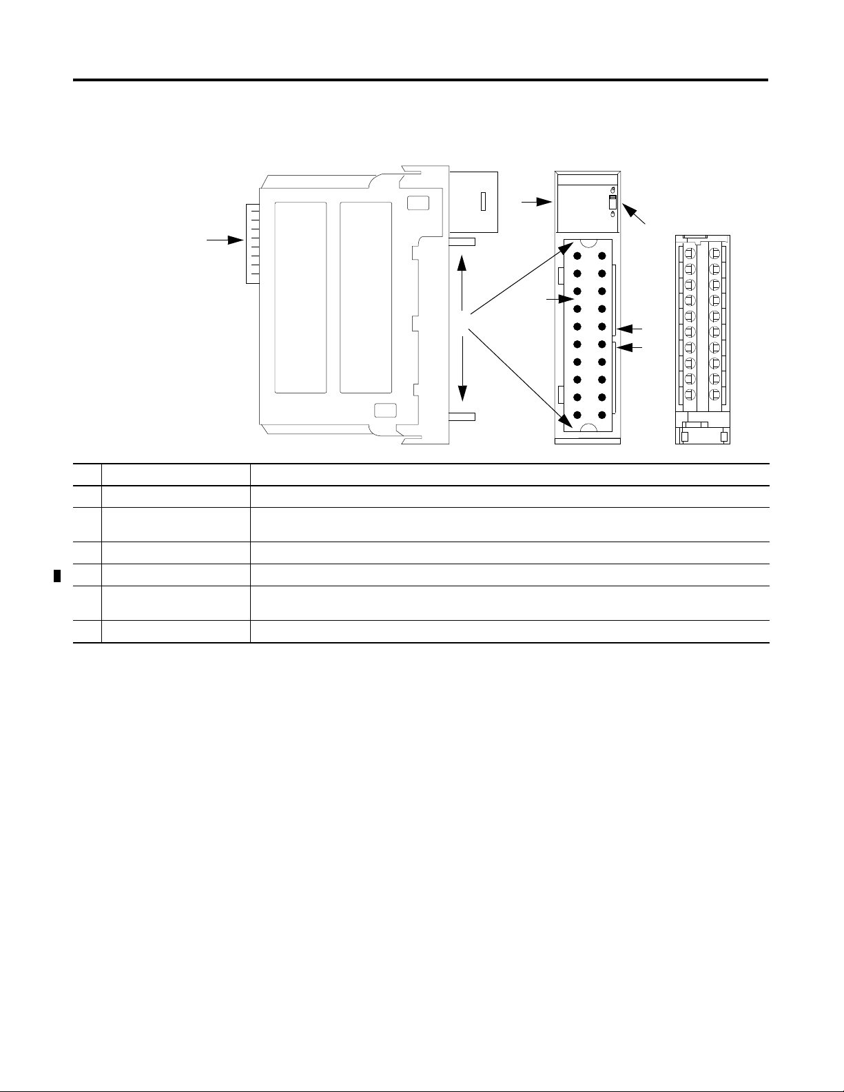
Chapter 1 ControlLogix HART Analog I/O Modules
Removable
Te rm in al
Block (RTB)
45118
1
2
3
4
5
6
Module Components
# Physical Feature Description
1 Backplane connector The backplane connector interface for the ControlLogix system connects the module to the ControlBus backplane.
2 Connector pins Input/output, power, and grounding connections are made to the module through these pins with the use of a
removable terminal block (RTB) or interface module (IFM).
3 Locking tab The locking tab anchors the RTB or IFM cable on the module, maintaining wiring connections.
4 Slots for keying Mechanically keys the RTB to prevent inadvertently making the wrong wire connections to the module.
5 Status indicators Indicators display the status of communication, module health, and input and output devices. Use these indicators
to help in troubleshooting.
6 Top and bottom guides Guides provide assistance in seating the RTB or IFM cable onto the module.
This figure shows the physical features of the ControlLogix analog I/O modules.
HART Communication
The HART field communication protocol is widely accepted in industry as a
standard for digitally enhanced 4…20 mA communication with smart
(microprocessor-based) field devices. A digital signal is superimposed onto the
4…20 mA current loop to provide two means of communication from the device.
The 4…20 mA analog channel lets a single process variable be communicated at
the fastest possible rate while the digital channel provides access to multiple
process variables, data quality, and device status information. The HART
protocol lets these simultaneous communication channels be used in a
complementary fashion.
The modules support the HART protocol and perform these distinct operations:
• Convert to or from 4…20 mA analog signals and digital numeric values in
engineering units used in the Logix controller.
• Collect dynamic process data automatically from the connected HART
field device, such as temperature, pressure, flow, or valve position.
• Configure and troubleshoot the HART Field Device by using FactoryTalk
AssetCentre service from your control room.
14 Rockwell Automation Publication 1756-UM533C-EN-P - February 2011
Page 15
ControlLogix HART Analog I/O Modules Chapter 1
Analog
Signal
The Highway Addressable Remote Transducer
(HART) protocol supports two-way digital
communication, complements traditional
4…20 mA analog signals, and includes the
following features:
· Predefined commands
- Common practice
- General purpose
- Device specific
· Large installed base
· Worldwide support
Analog
Signal
+0.5 mA
0.5 mA
0
1200
Hz
"1"
2200
Hz
"0"
HART Signal
Time (seconds)
0 1 2
20 mA
Analog
Signal
4 mA
See the figure
(1)
that shows information about the HART protocol.
With the ControlLogix HART analog I/O modules, field device data can be
accessed by both the controller and device maintenance and management
software.
The ControlLogix HART analog I/O modules support Command-response
communication protocol and point-to-point wiring architecture.
(1) The figure is from the HART Communication Protocol Specifications, April, 2001, Revision 6.0, HART
Communication Foundation, All Rights Reserved.
Rockwell Automation Publication 1756-UM533C-EN-P - February 2011 15
Page 16
Chapter 1 ControlLogix HART Analog I/O Modules
Primary Master
Secondary Master
(handheld communicator
as secondary master)
Slave
44219
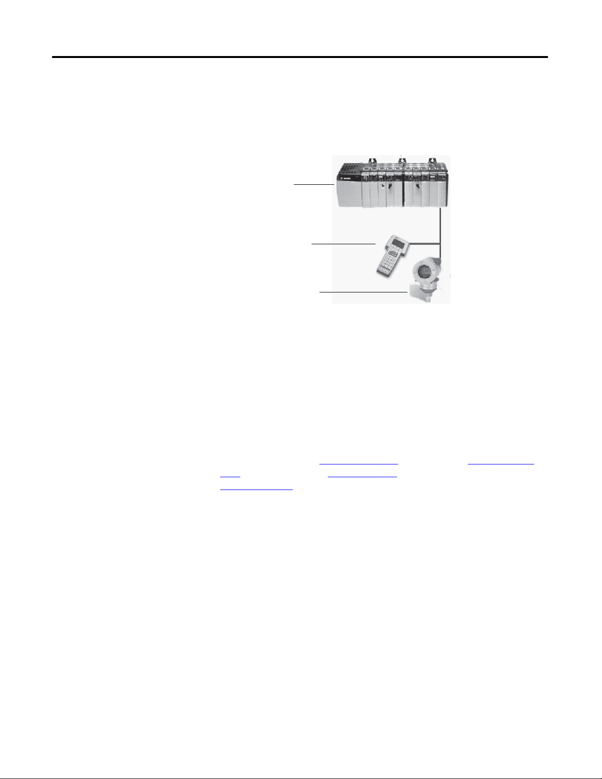
Commands can be accepted from either of two master devices. The controller is
one of the master devices and continuously obtains information from the field
device. The second master can typically be device maintenance, for example a
handheld communicator, as shown below.
Integrated HART Networks
Most transmitters are available with a HART protocol interface. The type of data
available is dependent on the type of instrument.
An example application is a smart mass flowmeter. By using just the standard
mA signal from the flowmeter it provides one field measurement - flow. By using
the mA signal with HART provides additional process information. The
mA signal representing flow is still available. The HART configuration of the
flowmeter can be set for primary value (PV)
(SV) being static pressure, third value (TV) being temperature, and
fourth value (FV)
being a digital representation of the mA signal.
In addition to these additional process variables, device status is also provided via
HART. Instead of one process variable, the controller sees four process variables,
has a check on the mA signal, and has a reading of device status. HART
connectivity provides all this with no changes to the existing 4…20 mA wiring.
This HART connectivity also provides remote configuration and
troubleshooting of field devices by using software, such as FactoryTalk
AssetCentre or Endress+Hauser FieldCare software.
being mass flow, secondary value
16 Rockwell Automation Publication 1756-UM533C-EN-P - February 2011
HART-enabled I/O Modules
The ControlLogix HART analog I/O modules have HART modems built in,
so there is no need to install external HART multiplexors or clip on
HART modems.
Page 17
ControlLogix HART Analog I/O Modules Chapter 1
EtherNet/IP Network
Asset Management Software
44220
Asset Management
Software
Electronic Keying
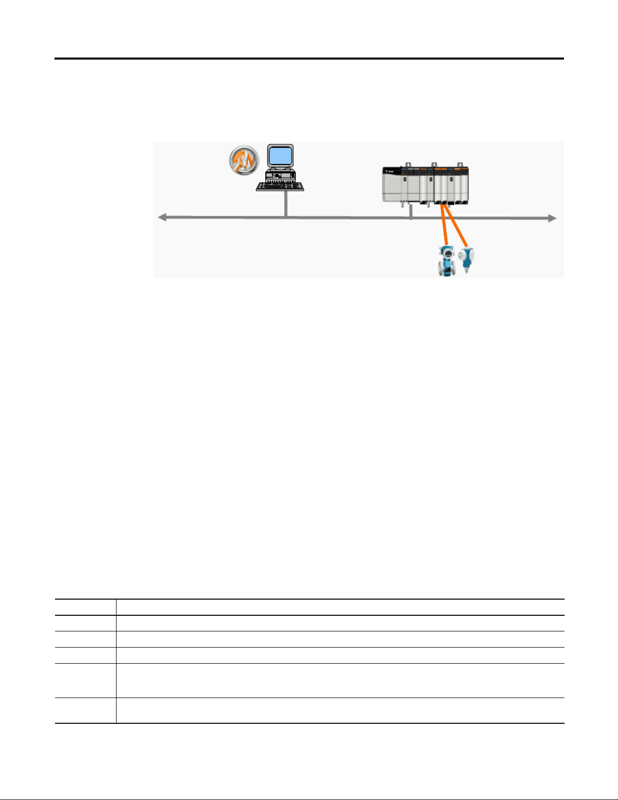
You can use the modules with asset management software. The following figure
shows the use of asset management software, such as FactoryTalk AssetCentre
software or Endress+Hauser FieldCare software.
The electronic keying feature automatically compares the expected module, as
shown in the RSLogix 5000 I/O Configuration tree, to the physical module
before I/O communication begins. You can use electronic keying to help prevent
communication to a module that does not match the type and revision expected.
For each module in the I/O Configuration tree, the user-selected keying option
determines if, and how, an electronic keying check is performed. Typically, three
keying options are available.
• Exact Match
• Compatible Keying
• Disable Keying
You must carefully consider the benefits and implications of each keying option
when selecting between them. For some specific module types, fewer options are
available.
Electronic keying is based on a set of attributes unique to each product revision.
When a Logix5000 controller begins communicating with a module, this set of
keying attributes is considered.
Table 1 - Keying Attributes
Attribute Description
Vendor The manufacturer of the module, for example, Rockwell Automation/Allen-Bradley.
Product Type The general type of the module, for example, communication adapter, AC drive, or digital I/O.
Product Code The specific type of module, generally represented by its catalog number, for example, 1756-IB16I.
Major Revision A number that represents the functional capabilities and data exchange formats of the module. Typically, although not always, a later,
Minor Revision A number that indicates the module’s specific firmware revision. Minor Revisions typically do not impact data compatibility but may
that is higher, Major Revision supports at least all of the data formats supported by an earlier, that is lower, Major Revision of the same
catalog number and, possibly, additional ones.
indicate performance or behavior improvement.
Rockwell Automation Publication 1756-UM533C-EN-P - February 2011 17
Page 18
Chapter 1 ControlLogix HART Analog I/O Modules
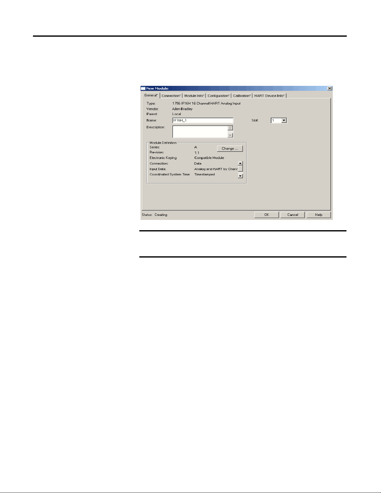
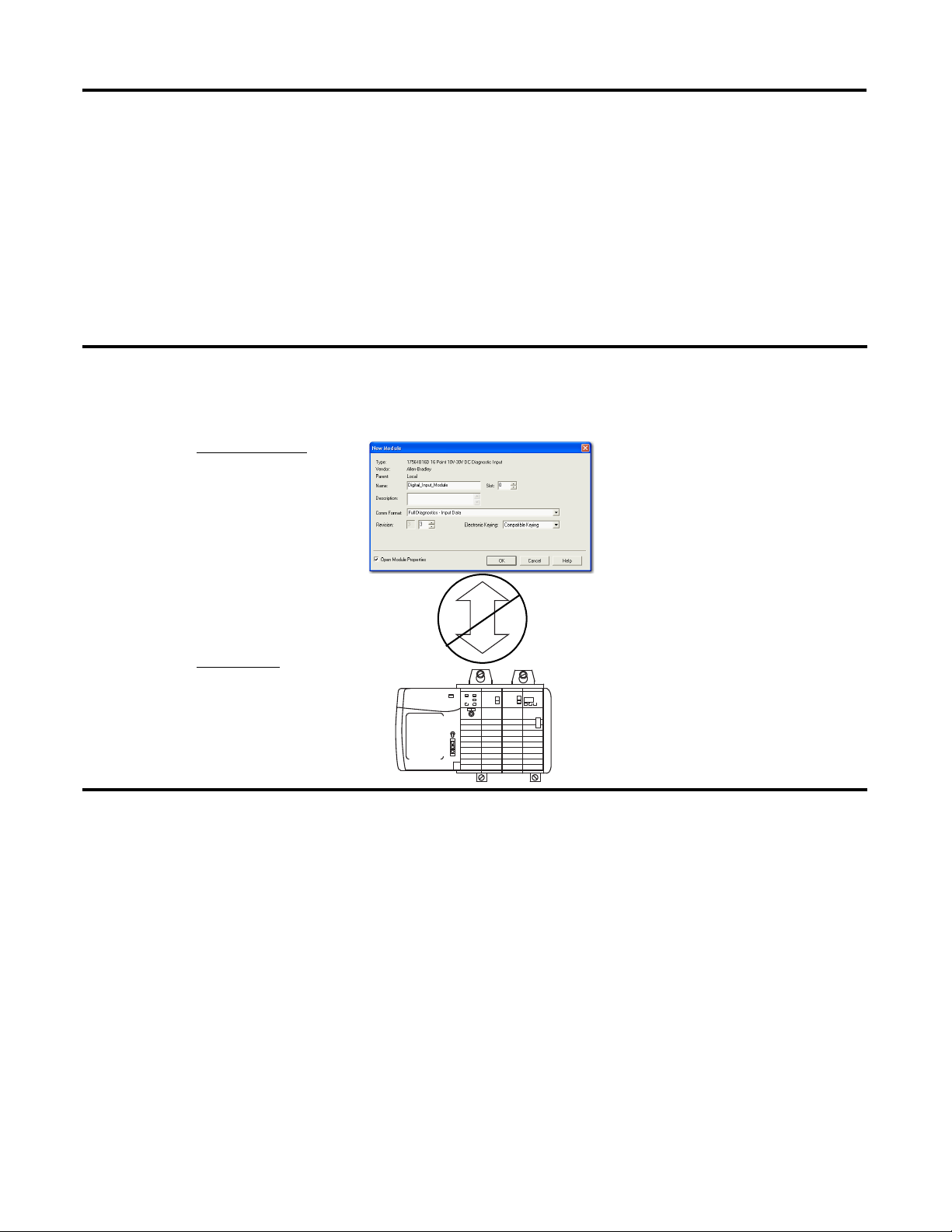
IMPORTANT
You can find revision information on the General tab of a module’s Properties
dialog box.
Figure 1 - General Tab
Changing electronic keying selections online may cause the I/O
communication connection to the module to be disrupted and may
result in a loss of data.
Exact Match
Exact Match keying requires all keying attributes, that is, Vendor, Product Type,
Product Code (catalog number), Major Revision, and Minor Revision, of the
physical module and the module created in the software to match precisely to
establish communication. If any attribute does not match precisely, I/O
communication is not permitted with the module or with modules connected
through it, as in the case of a communication module.
Use Exact Match keying when you need the system to verify that the module
revisions in use are exactly as specified in the project, such as for use in highlyregulated industries. Exact Match keying is also necessary to enable Automatic
Firmware Update for the module via the Firmware Supervisor feature from a
Logix5000 controller.
18 Rockwell Automation Publication 1756-UM533C-EN-P - February 2011
Page 19
ControlLogix HART Analog I/O Modules Chapter 1
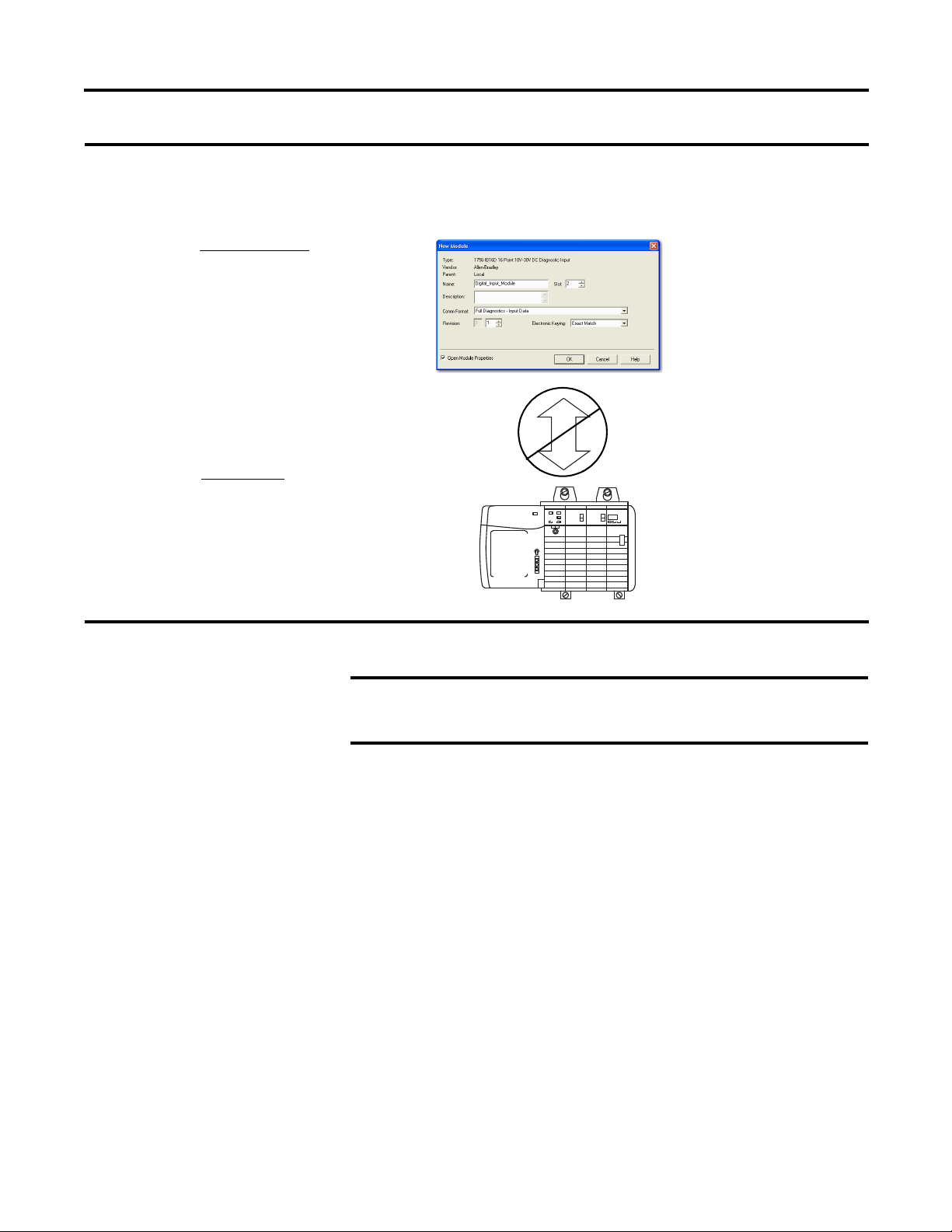
EXAMPLE
Module Configuration
Vendor = Allen-Bradley
Product Type = Digital Input
Module
Catalog Number = 1756-IB16D
Major Revision = 3
Minor Revision = 1
Communication is prevented.
Physical Module
Vendor = Allen-Bradley
Product Type = Digital Input
Module
Catalog Number = 1756-IB16D
Major Revision = 3
Minor Revision = 2
IMPORTANT
In the following scenario, Exact Match keying prevents I/O communication.
The module configuration is for a 1756-IB16D module with module revision 3.1. The physical module is a 1756-IB16D
module with module revision 3.2. In this case, communication is prevented because the Minor Revision of the module
does not match precisely.
Changing electronic keying selections online may cause the I/O
Communication connection to the module to be disrupted and may
result in a loss of data.
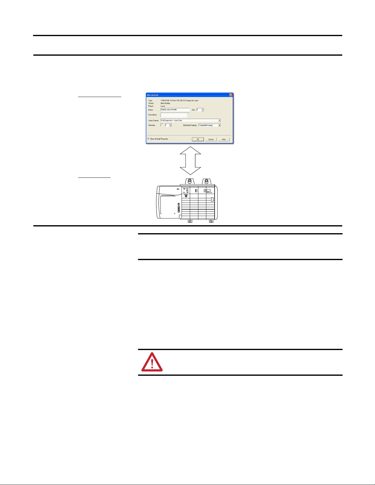
Compatible Keying
Compatible keying indicates that the module determines whether to accept or
reject communication. Different module families, communication adapters, and
module types implement the compatibility check differently based on the family
capabilities and on prior knowledge of compatible products.
Compatible keying is the default setting. Compatible keying allows the physical
module to accept the key of the module configured in the software, provided that
the configured module is one the physical module is capable of emulating. The
exact level of emulation required is product and revision specific.
With Compatible keying, you can replace a module of a certain Major Revision
with one of the same catalog number and the same or later, that is higher, Major
Revision. In some cases, the selection makes it possible to use a replacement that is
a different catalog number than the original. For example, you can replace a
1756-CNBR module with a 1756-CN2R module.
Rockwell Automation Publication 1756-UM533C-EN-P - February 2011 19
Page 20
Chapter 1 ControlLogix HART Analog I/O Modules
EXAMPLE
Module Configuration
Vendor = Allen-Bradley
Product Type = Digital Input
Module
Catalog Number = 1756-IB16D
Major Revision = 3
Minor Revision = 3
Physical Module
Vendor = Allen-Bradley
Product Type = Digital Input
Module
Catalog Number = 1756-IB16D
Major Revision = 3
Minor Revision = 2
Communication is prevented.
In the following scenario, Compatible keying prevents I/O communication:
The module configuration is for a 1756-IB16D module with module revision 3.3. The physical module is a 1756-IB16D
module with module revision 3.2. In this case, communication is prevented because the minor revision of the module is
lower than expected and may not be compatible with 3.3.
Release notes for individual modules indicate the specific compatibility details.
When a module is created, the module developers consider the module’s
development history to implement capabilities that emulate those of the previous
module. However, the developers cannot know future developments. Because of
this, when a system is configured, we recommend that you configure the module
by using the earliest, that is, lowest, revision of the physical module that you
believe will be used in the system. By doing this, you can avoid the case of a
physical module rejecting the keying request because it is an earlier revision than
the one configured in the software.
20 Rockwell Automation Publication 1756-UM533C-EN-P - February 2011
Page 21
ControlLogix HART Analog I/O Modules Chapter 1
EXAMPLE
Module Configuration
Vendor = Allen-Bradley
Product Type = Digital Input
Module
Catalog Number = 1756-IB16D
Major Revision = 2
Minor Revision = 1
Physical Module
Vendor = Allen-Bradley
Product Type = Digital Input
Module
Catalog Number = 1756-IB16D
Major Revision = 3
Minor Revision = 2
Communication is allowed.
IMPORTANT
In the following scenario, Compatible keying allows I/O communication:
The module configuration is for a 1756-IB16D module with module revision 2.1. The physical module is a 1756-IB16D
module with module revision 3.2. In this case, communication is allowed because the major revision of the physical
module is higher than expected and the module determines that it is compatible with the prior major revision.
Changing electronic keying selections online may cause the I/O
communication connection to the module to be disrupted and may result
in a loss of data.
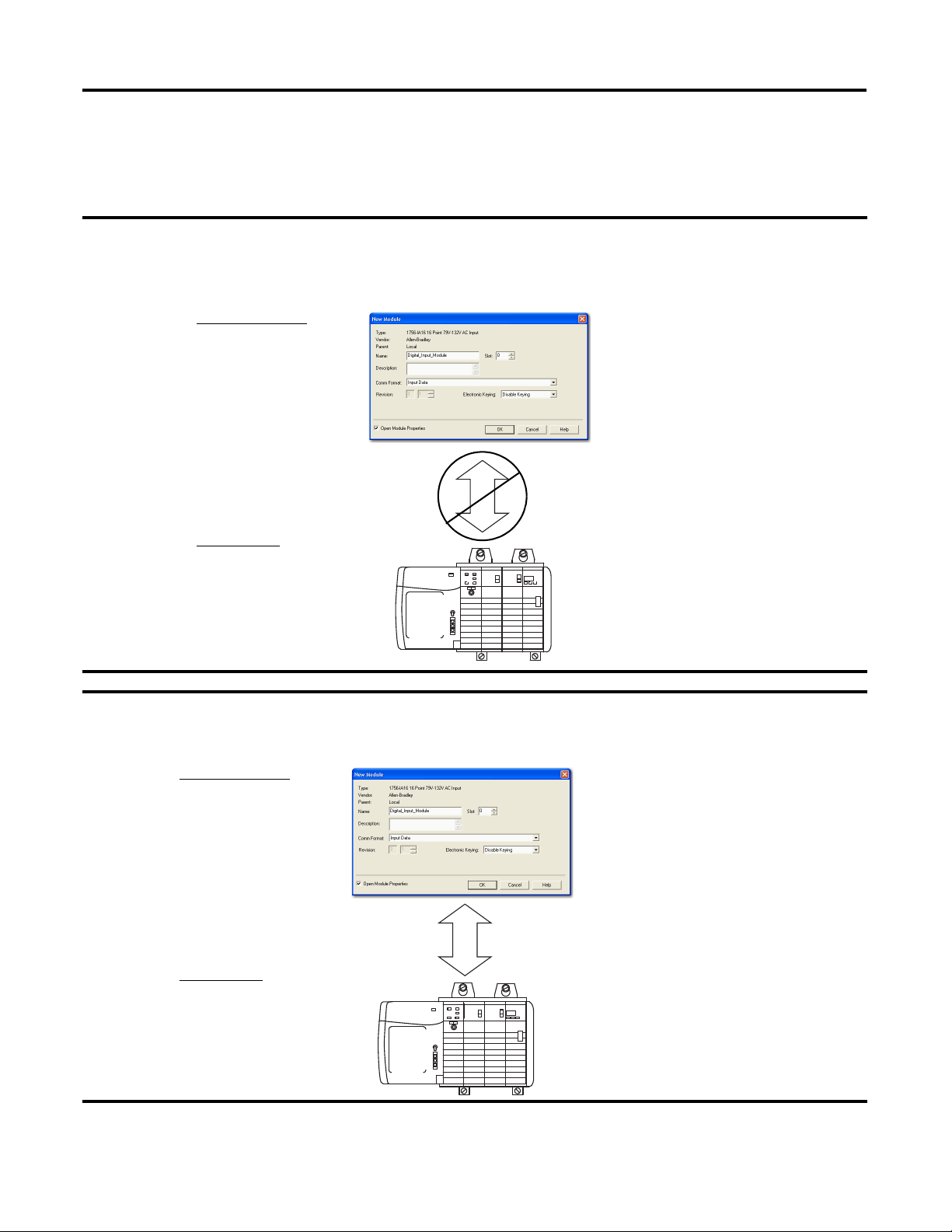
Disabled Keying
Disabled keying indicates the keying attributes are not considered when
attempting to communicate with a module. Other attributes, such as data size and
format, are considered and must be acceptable before I/O communication is
established. With Disabled keying, I/O communication may occur with a
module other than the type specified in the I/O Configuration tree with
unpredictable results. We generally do not recommend using Disabled keying.
ATTENTION: Be extremely cautious when using Disabled keying; if used
incorrectly, this option can lead to personal injury or death, property
damage, or economic loss.
Rockwell Automation Publication 1756-UM533C-EN-P - February 2011 21
Page 22
Chapter 1 ControlLogix HART Analog I/O Modules
EXAMPLE
EXAMPLE
Module Configuration
Vendor = Allen-Bradley
Product Type = Digital Input
Module
Catalog Number = 1756-IA16
Major Revision = 3
Minor Revision = 1
Physical Module
Vendor = Allen-Bradley
Product Type = Analog Input
Module
Catalog Number = 1756-IF16
Major Revision = 3
Minor Revision = 2
Communication is prevented.
Module Configuration
Vendor = Allen-Bradley
Product Type = Digital Input
Module
Catalog Number = 1756-IA16
Major Revision = 2
Minor Revision = 1
Physical Module
Vendor = Allen-Bradley
Product Type = Digital Input
Module
Catalog Number = 1756-IB16
Major Revision = 3
Minor Revision = 2
Communication is allowed.
In the following scenario, Disable keying prevents I/O communication:
The module configuration is for a 1756-IA16 digital input module. The physical module is a 1756-IF16 analog input
module. In this case, communication is prevented because the analog module rejects the data formats that the
digital module configuration requests.
If you use Disabled keying, you must take full responsibility for understanding
whether the module that is being used can fulfill the functional requirements of
the application.
22 Rockwell Automation Publication 1756-UM533C-EN-P - February 2011
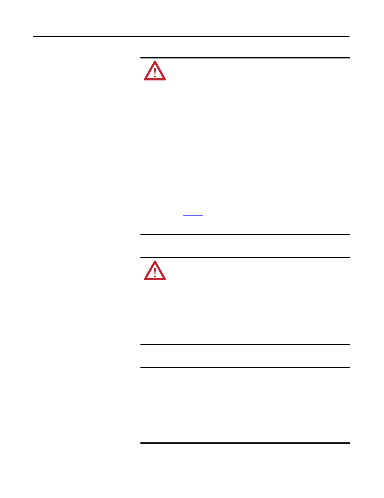
In the following scenario, Disable keying allows I/O communication:
The module configuration is for a 1756-IA16 digital input module. The physical module is a 1756-IB16 digital input
module. In this case, communication is allowed because the two digital modules share common data formats.
Page 23

ControlLogix HART Analog I/O Modules Chapter 1
IMPORTANT
Changing electronic keying selections online may cause the I/O
communication connection to the module to be disrupted and may
result in a loss of data.
Timestamping
Controllers within the ControlLogix chassis maintain a system clock. This clock
is also known as the coordinated system time (CST). You can configure your
analog I/O modules to access this clock and timestamp input data or output echo
data when the module multicasts to the system.
This feature provides accurate calculations between events to help you identify
the sequence of events in either fault conditions or in the course of normal I/O
operations. The system clock can be used between multiple modules in the
same chassis.
Each module maintains a rolling timestamp that is unrelated to the coordinated
system time. The rolling timestamp is a continuously running 15-bit timer that
counts in milliseconds.
For input modules, whenever a module scans its channels, it also records the value
of the rolling timestamp at that time. Your program can then use the last two
rolling timestamp values and calculate the interval between receipt of data or the
time when new data was received.
For output modules, the rolling timestamp value is updated only when new values
are applied to the Digital to Analog Converter (DAC).
Rockwell Automation Publication 1756-UM533C-EN-P - February 2011 23
Page 24

Chapter 1 ControlLogix HART Analog I/O Modules
Module Scaling
When using scaling, you change a quantity from one notation to another.
To scale a channel, choose two points along the module's operating range and
apply corresponding low and high unit values to those points.
Scaling lets you configure the module to return data to the controller in units that
match the quantity being measured. For example, the analog input module can
provide the temperature in degrees Celsius or the pressure in mbar. An analog
output module might have commanded values represented in % of stroke of a
valve. This makes it easier to use the values in your control program than by using
the raw signal value in mA.
Units like gallons, percent, mbar, psi, celsius, liters, and liters/minute are referred
to as Engineering Units.
For more information about scaling, see Scaling to Engineering Units on page 98
.
24 Rockwell Automation Publication 1756-UM533C-EN-P - February 2011
Page 25

Module Installation
Chapter
2
Introduction
The 1756-IF8H, 1756-OF8H, and 1756-IF16H analog modules use the HART
protocol with eight and 16 channels, respectively. This chapter describes basic
installation procedures.
The table explains the topics discussed in this chapter.
Topic Page
Environment and Enclosure 26
Preventing Electrostatic Discharge 26
European Hazardous Location Approval 26
North American Hazardous Location Approval 27
Removal and Insertion Under Power (RIUP) 28
Before You Begin 28
Module Accessories 28
Power Requirements 29
Install the Module 30
Key the Removable Terminal Block/Interface Module 31
Wire the Removable Terminal Block 32
Ground the Module 32
Wire the Module 34
Removal Terminal Block Assembly and Installation 34
Remove the Removable Terminal Block 36
Remove the Module 37
Rockwell Automation Publication 1756-UM533C-EN-P - February 2011 25
Page 26
Chapter 2 Module Installation
Environment and Enclosure
ATT ENTI ON: This equipment is intended for use in a Pollution Degree 2
industrial environment, in overvoltage Category II applications (as defined in
IEC 60664-1), at altitudes up to 2000 m (6562 ft) without derating.
This equipment is considered Group 1, Class A industrial equipment
according to IEC/CISPR 11. Without appropriate precautions, there may be
difficulties with electromagnetic compatibility in residential and other
environments due to conducted and radiated disturbances.
This equipment is supplied as open-type equipment. It must be mounted
within an enclosure that is suitably designed for those specific environmental
conditions that will be present and appropriately designed to prevent
personal injury resulting from accessibility to live parts. The enclosure must
have suitable flame-retardant properties to prevent or minimize the spread of
flame, complying with a flame spread rating of 5VA, V2, V1, V0 (or equivalent)
if non-metallic. The interior of the enclosure must be accessible only by the
use of a tool. Subsequent sections of this publication may contain additional
information regarding specific enclosure type ratings that are required to
comply with certain product safety certifications.
In addition to this publication, see the following:
• Industrial Automation Wiring and Grounding Guidelines, publication
1770-4.1
, for additional installation requirements
• NEMA Standard 250 and IEC 60529, as applicable, for explanations of the
degrees of protection provided by enclosures
Preventing Electrostatic Discharge
European Hazardous Location Approval
ATTENTION: This equipment is sensitive to electrostatic discharge, which
can cause internal damage and affect normal operation. Follow these
guidelines when you handle this equipment:
• Touch a grounded object to discharge potential static.
• Wear an approved grounding wriststrap.
• Do not touch connectors or pins on component boards.
• Do not touch circuit components inside the equipment.
• Use a static-safe workstation, if available.
• Store the equipment in appropriate static-safe packaging when not in
use.
European Zone 2 Certification
(The following applies when the product bears the EX marking.)
This equipment is intended for use in potentially explosive atmospheres as defined by
European Union Directive 94/9/EC and has been found to comply with the Essential
Health and Safety Requirements relating to the design and construction of Category 3
equipment intended for use in Zone 2 potentially explosive atmospheres, given in Annex II
to this Directive.
Compliance with the Essential Health and Safety Requirements has been assured by
compliance with EN 60079-15 and EN 60079-0.
26 Rockwell Automation Publication 1756-UM533C-EN-P - February 2011
Page 27
North American Hazardous Location Approval
Module Installation Chapter 2
WARNING:
• This equipment must be installed in an enclosure providing at least IP54
protection when applied in Zone 2 environments.
• This equipment shall be used within its specified ratings defined by
Rockwell Automation.
• Provision shall be made to prevent the rated voltage from being exceeded
by transient disturbances of more than 40% when applied in Zone 2
environments.
• This equipment must be used only with ATEX certified Rockwell
Automation backplanes.
• Secure any external connections that mate to this equipment by using
screws, sliding latches, threaded connectors, or other means provided
with this product.
• Do not disconnect equipment unless power has been removed or the area
is known to be nonhazardous.
The following information applies when operating this
equipment in hazardous locations:
Products marked "CL I, DIV 2, GP A, B, C, D" are suitable for use in
Class I Division 2 Groups A, B, C, D, Hazardous Locations and
nonhazardous locations only. Each product is supplied with
markings on the rating nameplate indicating the hazardous
location temperature code. When combining products within a
system, the most adverse temperature code (lowest "T" number)
may be used to help determine the overall temperature code of the
system. Combinations of equipment in your system are subject to
investigation by the local Authority Having Jurisdiction at the time
of installation.
EXPLOSION HAZARD
• Do not disconnect equipment unless power
has been removed or the area is known to be
nonhazardous.
• Do not disconnect connections to this
equipment unless power has been removed or
the area is known to be nonhazardous. Secure
any external connections that mate to this
equipment by using screws, sliding latches,
threaded connectors, or other means provided
with this product.
• Substitution of components may impair
suitability for Class I, Division 2.
• If this product contains batteries, they must
only be changed in an area known to be
nonhazardous.
Informations sur l’utilisation de cet équipement en
environnements dangereux:
Les produits marqués "CL I, DIV 2, GP A, B, C, D" ne conviennent qu'à
une utilisation en environnements de Classe I Division 2 Groupes A, B,
C, D dangereux et non dangereux. Chaque produit est livré avec des
marquages sur sa plaque d'identification qui indiquent le code de
température pour les environnements dangereux. Lorsque plusieurs
produits sont combinés dans un système, le code de température le
plus défavorable (code de température le plus faible) peut être utilisé
pour déterminer le code de température global du système. Les
combinaisons d'équipements dans le système sont sujettes à
inspection par les autorités locales qualifiées au moment de
l'installation.
RISQUE D’EXPLOSION
• Couper le courant ou s'assurer que
l'environnement est classé non dangereux avant
de débrancher l'équipement.
• Couper le courant ou s'assurer que
l'environnement est classé non dangereux avant
de débrancher les connecteurs. Fixer tous les
connecteurs externes reliés à cet équipement à
l'aide de vis, loquets coulissants, connecteurs
filetés ou autres moyens fournis avec ce produit.
• La substitution de composants peut rendre cet
équipement inadapté à une utilisation en
environnement de Classe I, Division 2.
• S'assurer que l'environnement est classé non
dangereux avant de changer les piles.
Rockwell Automation Publication 1756-UM533C-EN-P - February 2011 27
Page 28
Chapter 2 Module Installation
IMPORTANT
Removal and Insertion Under Power (RIUP)
Before You Begin
WARNING: When you insert or remove the module while backplane
power is on, an electrical arc can occur. This could cause an explosion in
hazardous location installations.
Be sure that power is removed or the area is nonhazardous before
proceeding. Repeated electrical arcing causes excessive wear to contacts on
both the module and its mating connector. Worn contacts may create
electrical resistance that can affect module operation.
ATTENTION: This equipment is not resistant to sunlight or other sources
of UV radiation.
Before you install your module, you should have already:
• Installed and grounded a 1756 chassis and power supply.
• Ordered and received a removable terminal block (RTB) or
1492 interface module (IFM) and its components for your application.
Module Accessories
These modules mount in a ControlLogix chassis and use a separately-ordered
removable terminal block (RTB) or a 1492 interface module (IFM) to connect all
field-side wiring.
The ControlLogix HART analog modules use one of the following RTBs and
support these IFMs.
Module RTBs
1756-IF8H • 1756-TBCH 36-position cage clamp RTB
1756-IF16H • 1756-TBCH 36-position cage clamp RTB
1756-OF8H • 1756-TBNH 20-position NEMA RTB
(1) Use an extended-depth cover (1756-TBE) for applications with heavy gauge wiring or requiring additional
routing space.
(2) See the IFMs for the respective modules on page 192. Consult the documentation that came with it to connect
all wiring.
(1)
• 1756-TBS6H 36-position spring clamp RTB
• 1756-TBS6H 36-position spring clamp RTB
• 1756-TBSH 20-position spring clamp RTB
ATTENTION: The ControlLogix system has been agency certified using only
the ControlLogix RTBs (catalog numbers 1756-TBCH and 1756-TBS6H). Any
application that requires agency certification of the ControlLogix system
using other wiring termination methods may require application specific
approval by the certifying agency.
(2)
IFMs
• 1492-ACABLExUD (current)
• 1492-ACABLExUC (voltage)
• 1492-ACABLExUB
• 1492-ACABLExWB (current)
• 1492-ACABLExWA (voltage)
28 Rockwell Automation Publication 1756-UM533C-EN-P - February 2011
Page 29
Module Installation Chapter 2
IMPORTANT
Power Requirements
ATTENTION: To comply with the CE low voltage directive (LVD), all
connected I/O must be powered from a source compliant with safety extra
low voltage (SELV) or protected extra low voltage (PELV).
WARNING: Use supply wires suitable for 30 °C (86 °F) above
surrounding ambient.
These modules receive power from the 1756 chassis power supply and require
these two sources of power from the backplane.
Module Power Requirements, max
1756-IF8H • 300 mA at 5.1V DC
• 135 mA at 24V DC
1756-IF16H • 200 mA at 5.1V DC
• 125 mA at 24V DC
1756-OF8H • 200 mA at 5.1 V DC
• 230 mA at 24 V DC
The 1756-OF8H module requires more power than the standard 1756-OF8
module. You can have a maximum of 12 1756-OF8H modules per chassis.
ATTENTION: Personnel responsible for the application of safety-related
programmable electronic systems (PES) shall be aware of the safety
requirements in the application of the system and shall be trained in using
the system.
Rockwell Automation Publication 1756-UM533C-EN-P - February 2011 29
Page 30
Chapter 2 Module Installation
20861
Locking Tab
20862
Install the Module
You can install or remove the module while chassis power is applied.
ATTENTION: The module is designed to support removal and insertion
under power (RIUP). However, when you remove or insert an RTB with fieldside power applied, unintended machine motion or loss of process control
can occur. Exercise extreme caution when using this feature.
1. Align the circuit board with the top and bottom chassis guides.
2. Slide the module into the chassis until the module locking tabs click.
30 Rockwell Automation Publication 1756-UM533C-EN-P - February 2011
Page 31

Module Installation Chapter 2
U-shaped
Bands
20850
Wedge-shaped Tab
20851
Key the Removable Terminal Block/Interface Module
Wedge-shaped keying tabs and U-shaped keying bands come with your RTB to
prevent connecting the wrong wires to your module. Key the positions on the
module that correspond to unkeyed positions on the RTB. For example, if you
key the first position on the module, leave the first position on the RTB unkeyed.
1. To key the module, insert the U-shaped band and push the band until it
snaps into place.
2. To key the RTB/IFM, insert the wedge-shaped tab with the rounded edge
first and push the tab until it stops.
You can reposition the tabs to re-key future module applications.
Rockwell Automation Publication 1756-UM533C-EN-P - February 2011 31
Page 32

Chapter 2 Module Installation
IMPORTANT
a.Remove a
length of cable
jacket from the
connecting cable.
b.Pull the foil
shield and bare the
drain wire from the
insulated wire.
c.Twist the foil shield
and drain wire
together to form a
single strand.
d.Attach a ground lug
and apply heat shrink
tubing to the exit
area.
20104
Drain Wire
Field
Device
43183
Wire the Removable Terminal Block
Ground the Module
WARNING: If you connect or disconnect wiring while the field-side
power is on, an electrical arc can occur. This could cause an explosion in
hazardous location installations. Be sure that power is removed or the
area is nonhazardous before proceeding.
Wire the RTB with a 3.3 mm (0.13 in.) screwdriver before installing it onto the
module. Shielded cable is required when using this module. We recommend
using Belden 8761 cable to wire the RTB. The RTB terminations can
accommodate 2.1…0.25 mm
2
(14…22 AWG) shielded wire and a torque
of 0.5 N•m (4.4 lb•in.).
ATTENTION: When using the 1756-TBCH RTB, do not wire more than two
2
0.33...1.3 mm
(22...16 AWG) conductors on any single terminal. Use only the
same size wires with no intermixing of solid and stranded wire types.
When using the 1756-TBS6H RTB, do not wire more than 1 conductor on any
single terminal.
Use the following information to ground the module.
Connect the Grounded End of the Cable
1. Ground the drain wire.
We recommend grounding the drain wire at the field-side. If you cannot
ground at the field-side, ground at an earth ground on the chassis as
shown.
2. Connect the insulated wires to the field-side.
32 Rockwell Automation Publication 1756-UM533C-EN-P - February 2011
Page 33

Module Installation Chapter 2
Chassis Mounting Tab
Drain Wire with Ground Lug
4M or 5M (#10 or
#12) Phillips Screw
and Star Washer (or
SEM screw)
4M or 5M (#10 or
#12) Star Washer
20918
Spring Clamp RTB
Cage Clamp RTB
a. Strip 10 mm (0.4 in.) maximum length
of wire.
b. Insert the screwdriver into the inner
hole of the RTB.
c. Insert the wire into the open terminal
and remove the screwdriver.
a. Strip 8.3 mm (0.33 in.) maximum length
of wire.
b. Insert the wire into the open terminal.
c. Turn the screw clockwise to close the
terminal on the wire.
If you cannot ground at the field device, follow these steps.
1. Prepare one end of the cable as shown in step 1 on page 32
Ground at an earth ground on the chassis.
Connect the drain wire to a chassis mounting tab. Use any chassis
mounting tab that is designated as a functional signal ground.
2. Connect the insulated wires to the field device.
.
Connect the Ungrounded End of the Cable
Follow these steps to connect the ungrounded end of the cable to the clamp.
1. Cut the foil shield and drain wire back to the cable casing and apply shrink
wrap.
2. Connect the insulated wires to the RTB.
Rockwell Automation Publication 1756-UM533C-EN-P - February 2011 33
Page 34

Chapter 2 Module Installation
1
4
3
2
3
2
20858-M
Wire the Module
Removal Terminal Block Assembly and Installation
Refer to the individual module chapters for wiring information.
For this module Page
1756-IF8H 60
1756-IF16H 72
1756-OF8H 83
The following sections describe the steps needed to assemble and install the RTB.
Assemble the Removable Terminal Block and the Housing
1. Align the grooves at the bottom of each side of the housing with the
side edges of the RTB.
2. Slide the RTB into the housing until it snaps into place.
Item Description
1 Housing cover
2 Groove
3 Side edge of RTB
4 Strain relief area
34 Rockwell Automation Publication 1756-UM533C-EN-P - February 2011
Page 35

Module Installation Chapter 2
Module Guide
RTB
Guides
Locking Tab
20854
Install the Removable Terminal Block
WARNING: When you connect or disconnect the Removable Terminal
Block (RTB) with field side power applied, an electrical arc can occur. This
could cause an explosion in hazardous location installations.
Be sure that power is removed or the area is nonhazardous before
proceeding.
Before installing the RTB, make certain of the following items:
• The field-side wiring of the RTB has been completed.
• The RTB housing is snapped into place on the RTB.
• The RTB housing is closed.
• The locking tab at the top of the module is unlocked.
• The power is removed or the area is nonhazardous.
1. Align the side, top, and bottom RTB guides with the side, top, and bottom
module guides.
2. Press quickly and evenly to seat the RTB on the module until the latches
snap into place.
3. Slide the locking tab down to lock the RTB onto the module.
Rockwell Automation Publication 1756-UM533C-EN-P - February 2011 35
Page 36

Chapter 2 Module Installation
42517
20855
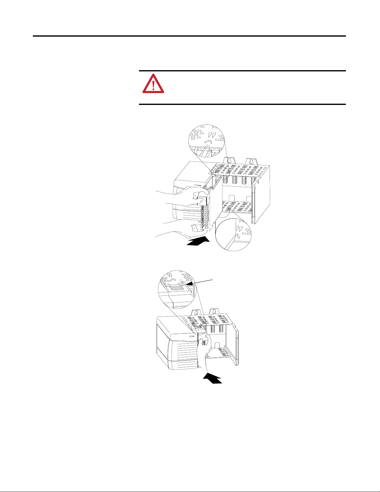
Remove the Removable Terminal Block
ATTENTION: The RTB is designed to support removal and insertion under
power (RIUP). However, when you remove or insert an RTB with field-side
power applied, unintended machine motion or loss of process control can
occur. Exercise extreme caution when using this feature. We recommended
that field-side power be removed before removing the module.
Before removing the module, you must remove the RTB.
1. Unlock the locking tab at the top of the module.
2. Open the RTB door and pull the RTB off the module.
36 Rockwell Automation Publication 1756-UM533C-EN-P - February 2011
Page 37

Module Installation Chapter 2
20856
20857
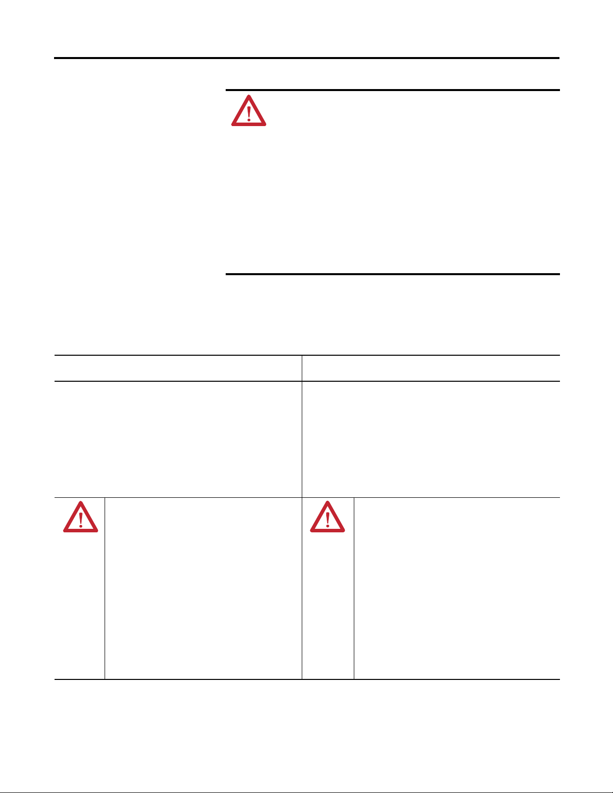
Remove the Module
Do these steps to remove a module.
1. Push in the top and bottom locking tabs.
2. Pull the module out of the chassis.
Rockwell Automation Publication 1756-UM533C-EN-P - February 2011 37
Page 38

Chapter 2 Module Installation
Notes:
38 Rockwell Automation Publication 1756-UM533C-EN-P - February 2011
Page 39

ControlLogix Module Operation
Chapter
3
Introduction
Every I/O module in the ControlLogix system must be owned by a ControlLogix
controller. This owner-controller stores configuration data for every module that
it owns and can be located locally or remotely, relative to the I/O module’s
position. The owner sends the I/O module configuration data to define the
module’s behavior and begin operation within the control system. Each
ControlLogix I/O module must continuously maintain communication with its
owner to operate normally.
Typically, each module in the system has only one owner. Input modules can have
more than one owner. Output modules are limited to a single owner.
By using the Producer/Consumer model, ControlLogix I/O modules can
produce data without having been polled by a controller first. The modules
produce the data and any owner or listen-only controller device can consume it.
For example, an input module produces data and any number of controllers can
consume the data at the same time. This eliminates the need for one controller to
send the data to another controller.
The table explains the topics discussed in this chapter.
Topic Page
Direct Connections 40
Input Module Operation 40
Input Modules in a Local Chassis 41
Input Modules in a Remote Chassis 44
Output Module Operation 46
Output Modules in a Local Chassis 46
Output Modules in a Remote Chassis 47
Listen-only Mode 49
Multiple Owners of Input Modules 49
Configuration Changes in an Input Module with Multiple Owners 51
Unicast Communication 51
Rockwell Automation Publication 1756-UM533C-EN-P - February 2011 39
Page 40

Chapter 3 ControlLogix Module Operation
Direct Connections
A direct connection is a real-time data transfer link between the controller and
the device that occupies the slot that the configuration data references.
ControlLogix analog I/O modules use direct connections only.
When module configuration data is downloaded to an owner-controller, the
controller attempts to establish a direct connection to each of the modules the
data references.
If a controller has configuration data referencing a slot in the control system, the
controller periodically checks for the presence of a device there. When a device’s
presence is first detected, the controller automatically sends the configuration
data and one of the following events occurs:
• If the data is appropriate to the module found in the slot, a connection is
made and operation begins.
• If the configuration data is not appropriate, the data is rejected and an error
code displays in the software. For example, a module’s configuration data
can be appropriate except for a mismatch in electronic keying that prevents
normal operation. For more information about error codes, see Module
Configuration Errors on page 160.
The controller maintains and monitors its connection with a module. Any break
in the connection, such as removal of the module from the chassis while under
power, causes the controller to set fault status bits in the data area associated with
the module. You can use ladder logic to monitor this data area and detect module
failures.
Input Module Operation
40 Rockwell Automation Publication 1756-UM533C-EN-P - February 2011
In the ControlLogix system, the owner-controller does not poll analog input
modules after a connection is established. The modules multicast their data
periodically. Multicast frequency depends on the options chosen during
configuration and where in the control system that input module physically
resides.
An input module’s communication, or multicasting, behavior varies depending
upon whether it operates in the local chassis or in a remote chassis, based on the
network type. The following sections detail the differences in data transfers
between these setups.
Page 41

ControlLogix Module Operation Chapter 3
IMPORTANT
1
2
On-board Memory
Status Data
Channel Data
Channel Data
Channel Data
Channel Data
Channel Data
Channel Data
Ch 0
Ch 1
Ch 2
Ch 3
Ch 4
Ch 5
Tim estam p
41361
Input Modules in a Local Chassis
When a module resides in the same chassis as the owner-controller, the following
configuration parameters affect how and when the input module multicasts data:
• Real-time sample
• Requested packet interval
Real Time Sample (RTS)
This configurable parameter instructs the module to perform the following
operations:
• Scan all of its input channels and store the data into on-board memory.
• Multicast the updated channel data (as well as other status data) to the
backplane of the local chassis.
The real time sample value is set during the initial configuration
using RSLogix 5000 software. This value can be adjusted
Rockwell Automation Publication 1756-UM533C-EN-P - February 2011 41
anytime.
Page 42

Chapter 3 ControlLogix Module Operation
On-board Memory
Status Data
Channel Data
Channel Data
Channel Data
Channel Data
Channel Data
Channel Data
Ch 0
Ch 1
Ch 2
Ch 3
Ch 4
Ch 5
Tim estamp
41362
IMPORTANT
Requested Packet Interval (RPI)
This configurable parameter also instructs the module to multicast its channel
and status data to the local chassis backplane.
The requested packet interval instructs the module to multicast the current
contents of its on-board memory when the requested packet interval expires (the
module does not update its channels prior to the multicast).
Figure 2 -
The requested packet interval value is set during the initial
module configuration using RSLogix 5000 software. This value
can be adjusted when the controller is in Program mode.
If the real time sample value is less than or equal to the requested packet interval,
each multicast of data from the module has updated channel information. In
effect, the module is only multicasting at the real time sample rate.
If the real time sample value is greater than the requested packet interval, the
module multicasts at both the real time sample rate and the requested packet
interval rate. Their respective values dictate how often the owner-controller
receives data and how many multicasts from the module contain updated channel
data.
42 Rockwell Automation Publication 1756-UM533C-EN-P - February 2011
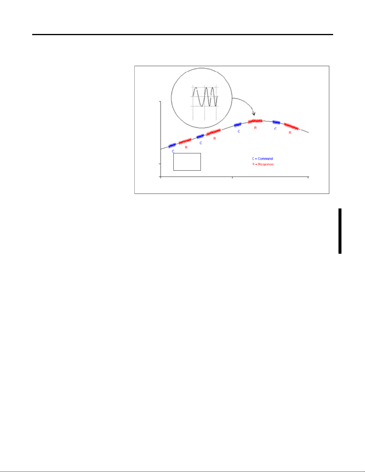
Page 43

ControlLogix Module Operation Chapter 3
Real Time Sample (RTS)
100 ms - Updated data
Requested Packet
Interval
25 ms - Same input data
as the previous RTS
25 50 75 100 125 150 175 200 225 250 275 300 325 350 375 400
Time (ms)
40946
IMPORTANT
In the example below, the real time sample value is 100 ms and the requested
packet interval value is 25 ms. Only every fourth multicast from the module
contains updated channel data.
Trigger Event Tasks
When configured to do so, ControlLogix analog input modules can trigger an
event task. The event task offers ControlLogix controller users a task that
executes a section of logic immediately when an event (receipt of new data)
occurs.
Your ControlLogix analog I/O module can trigger event tasks every real time
sample, after the module has sampled and multicast its data. Events tasks are
useful for synchronizing process variable (PV) samples and proportional integral
derivative (PID) calculations.
ControlLogix analog I/O modules can trigger event tasks at
every real time sample, but not at the requested packet
interval. For example, in the figure, an event task can be only
triggered every 100 ms.
Rockwell Automation Publication 1756-UM533C-EN-P - February 2011 43
Page 44

Chapter 3 ControlLogix Module Operation
ControlNet Network
Input data at least as often as RPI
Input data in remote
chassis at RTS and RPI
Owner-controller ControlNet Bridge Module ControlNet Bridge Module Input Module
Input Module in Remote Chassis with Requested Packet Interval Reserving Spot in Flow of Data
40947
Input Modules in a Remote Chassis
If an input module resides in a remote chassis, the role of the requested packet
interval and the module’s real time sample behavior change slightly with respect
to getting data to the owner-controller, depending on what network type you are
using to connect to the modules.
Remote Input Modules Connected Via ControlNet Network
When remote analog I/O modules are connected to the owner-controller via a
scheduled ControlNet network, the requested packet interval and real time
sample intervals still define when the module multicasts data within its own
chassis. However, only the value of the requested packet interval determines how
often the owner-controller receives it over the network.
When an requested packet interval value is specified for an input module in a
remote chassis connected by a scheduled ControlNet network, in addition to
instructing the module to multicast data within its own chassis, the requested
packet interval also reserves a spot in the stream of data flowing across the
ControlNet network.
The timing of this reserved spot does not coincide with the exact value of the
requested packet interval, but the control system guarantees that the ownercontroller receives data at least as often as the specified requested packet interval.
The reserved spot on the network and the module’s real time sample are
asynchronous to each other. This means there are best and worst case scenarios as
to when the owner-controller receives updated channel data from the module in a
networked chassis.
44 Rockwell Automation Publication 1756-UM533C-EN-P - February 2011
Page 45

ControlLogix Module Operation Chapter 3
TIP
Best Case Scenario - Real Time Sample
In the best case scenario, the module performs a real time sample multicast with
updated channel data just before the reserved network slot is made available. In
this case, the remotely-located owner-controller receives the data almost
immediately.
Worst Case Scenario - Real Time Sample
In the worst case scenario, the module performs a real time sample multicast just
after the reserved network slot has passed. In this case, the owner-controller does
not receive updated data until the next scheduled network slot.
Because it is the requested packet interval and not the real time sample that
dictates when the module’s data is sent over the network, we recommend the
requested packet interval value be set less than or equal to the real time sample to
make sure that updated channel data is received by the owner-controller with
each receipt of data.
Remote Input Modules Connected Via EtherNet/IP Network
When remote analog input modules are connected to the owner-controller via an
EtherNet/IP network, data is transferred to the owner-controller in the following
way:
• At the RTS or RPI (whichever is faster), the module broadcasts data
within its own chassis.
• The 1756 Ethernet bridge module in the remote chassis immediately
sends the module’s data over the network to the owner-controller as
long it has not sent data within a time frame that is one-quarter the
value of the analog input module’s RPI.
For example, if an analog input module uses an RPI = 100 ms, the
Ethernet module sends module data immediately on receiving it if
another data packet was not sent within the last 25 ms.
The Ethernet module will either multicast the module’s data to all
devices on the network or unicast to a specific owner-controller
depending on the setting of the Unicast box, as shown on page 93
For more information, see the Guidelines to Specify an RPI
Rate for I/O Modules section in the Logix5000 Controllers
Design Considerations Reference Manual,
publication
1756-RM094
.
.
Rockwell Automation Publication 1756-UM533C-EN-P - February 2011 45
Page 46
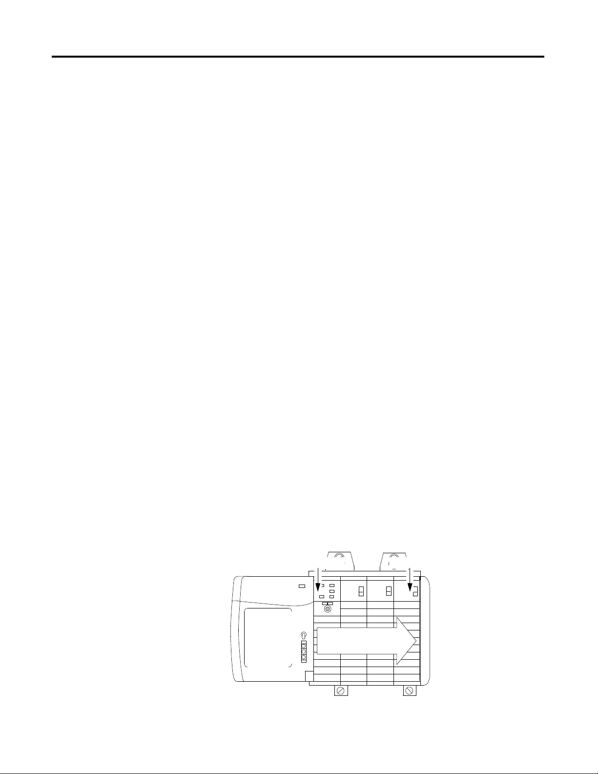
Chapter 3 ControlLogix Module Operation
TIP
Data sent from owner
at the RPI
Owner-controller Output Module
40949
Output Module Operation
The requested packet interval parameter governs exactly when an analog output
module receives data from the owner-controller and when the output module
echoes data. An owner-controller sends data to an analog output module at the
period specified in the requested packet interval. Data is not sent to the
module at the end of the controller’s program scan.
When an analog output module receives new data from an owner-controller
(every requested packet interval), the module automatically multicasts or echoes
a data value that corresponds to the analog signal present at the output terminals
to the rest of the control system. This feature, called Output Data Echo, occurs
whether the output module is local or remote.
If the output module is not responding according to how it has been
programmed, it could be for one of the following reasons:
• The commanded value falls outside the Configured Limits and is thus
being clamped.
• The commanded value changed faster than the configured max Rate
Limit, and is being clamped.
• The module is in Start-up Hold mode, following a connection break or
Run mode transition waiting for the control system to synchronize
with the prevailing setting to facilitate a bumpless startup.
Depending on the value of the requested packet interval, with respect to the
length of the controller program scan, the output module can receive and echo
data multiple times during one program scan.
Output Modules in a Local Chassis
When the requested packet interval is less than the program scan length, the
controller effectively lets the module’s output channels change values multiple
times during a single program scan because the output module is not dependent
on reaching the end of the program to send data.
When specifying a requested packet interval value for an analog output module,
you instruct the controller when to broadcast the output data to the module. If
the module resides in the same chassis as the owner-controller, the module
receives the data almost immediately after the controller sends it.
46 Rockwell Automation Publication 1756-UM533C-EN-P - February 2011
Page 47

ControlLogix Module Operation Chapter 3
ControlNet Network
Output data at least as
often as RPI
Immediate backplane
transfers to module
Data sent from
owner at module’s
RPI rate
Owner-controller ControlNet Bridge Module ControlNet Bridge Module Output Module
41360
Output Module in Remote Chassis with Requested Protocol Interval Reserving a Spot in Flow of Data
Output Modules in a Remote Chassis
If an output module resides in a remote chassis, the role of the requested packet
interval changes slightly with respect to getting data from the owner-controller,
depending on what network type you are using to connect to the modules.
Remote Output Modules Connected Via ControlNet Network
When remote analog output modules are connected to the owner-controller via a
scheduled ControlNet network, in addition to instructing the controller to
multicast the output data within its own chassis, the requested packet interval
also reserves a spot in the stream of data flowing across the ControlNet network.
The timing of this reserved spot does or does not coincide with the exact value of
the requested packet interval, but the control system will guarantee that the
output module will receive data at least as often as the specified requested packet
interval.
The reserved spot on the network and when the controller sends the output data
are asynchronous to each other. This means there are best and worst case
scenarios as to when the module receives the output data from the controller in a
networked chassis.
Rockwell Automation Publication 1756-UM533C-EN-P - February 2011 47
Page 48

Chapter 3 ControlLogix Module Operation
IMPORTANT
Best Case Scenario - Requested Packet Interval
In the best case scenario, the controller sends the output data just before the
reserved network slot is available. In this case, the remotely located output
module receives the data almost immediately.
Worst Case Scenario - Requested Packet Interval
In the worst case scenario, the controller sends the data just after the reserved
network slot has passed. In this case, the module does not receive the data until
the next scheduled network slot.
These best and worst case scenarios indicate the time required
for output data to transfer from the controller to the module once
the controller has produced it.
The scenarios do not take into account when the module will
receive new data (updated by the user program) from the
controller. That is a function of the length of the user program and
its asynchronous relationship with the requested protocol interval.
Remote Output Modules Connected Via EtherNet/IP Network
When remote analog output modules are connected to the owner-controller via
an EtherNet/IP network, the controller multicasts data in the following way:
• At the RPI, the owner-controller multicasts data within its own chassis.
• The 1756-ENBT module in the local chassis immediately sends the data
over the network to the analog output module as long as it has not sent
data within a time frame that is 1/4 the value of the analog module’s
requested protocol interval.
48 Rockwell Automation Publication 1756-UM533C-EN-P - February 2011
Page 49

ControlLogix Module Operation Chapter 3
IMPORTANT
IMPORTANT
Input Module
Configuration
Data
Xxxxx
Xxxxx
Xxxxx
Input Module
Configuration
Data
Xxxxx
Xxxxx
Xxxxx
Initial Configuration Initial Configuration
Controller A Controller BInput Module
CTR A CTR B
41056
Listen-only Mode
Any controller in the system can listen to the data from any I/O module (that is,
input data or ‘echoed’ output data) even if the controller does not own the
module. In other words, the controller does not have to own a module’s
configuration data to listen to it.
During the I/O configuration process, you can specify a ‘Listen-Only’ mode in
the Connection box of the Module Definition section on the Module Properties
dialog box. See page 91
for more details.
Choosing a ‘Listen-Only’ mode option lets the controller and module establish
communication without the controller sending any configuration data. In this
instance, another controller owns the module being listened to.
If a ‘Listen-Only’ connection is being used by any controller to the
module, any connections over the Ethernet network cannot use the
Unicast option. See the Unicast box on page 93
.
The ‘Listen-Only’ controller continues to receive multicast data
from the I/O module as long as a connection between an
owner-controller and I/O module is maintained.
If the connection between all owner-controllers and the module is
broken, the module stops multicasting data and connections to all
Listening controllers are also broken.
Multiple Owners of Input Modules
Because listening controllers lose their connections to modules when
communication with the owner stop, the ControlLogix system lets you define
more than one owner for input modules.
Only input modules can have multiple owners. If multiple owners
are connected to the same input module, they must maintain
identical configuration for that module.
In the example, Controller A and Controller B have both been configured to be
the owner of the input module.
Figure 3 - Multiple Owners with Identical Configuration Data
Rockwell Automation Publication 1756-UM533C-EN-P - February 2011 49
Page 50

Chapter 3 ControlLogix Module Operation
When multiple controllers are configured to own the same input module, the
following events occur:
• When the controllers begin downloading configuration data, both try to
establish a connection with the input module.
• Whichever controller’s data arrives first establishes a connection.
• When the second controller’s data arrives, the module compares it to its
current configuration data (the data received and accepted from the first
controller).
– If the configuration data sent by the second controller matches the
configuration data sent by the first controller the connection is also
accepted.
– If any parameter of the second configuration data is different from the
first, the module rejects the connection; RSLogix 5000 software alerts
you to the rejected connection through an error message.
The advantage of multiple owners over a Listen-only connection is that now
either of the controllers can lose the connection to the module and the module
continues to operate and multicast data to the system because of the connection
maintained by the other owner-controller.
50 Rockwell Automation Publication 1756-UM533C-EN-P - February 2011
Page 51

ControlLogix Module Operation Chapter 3
Input Module
Configuration
Data
Xxxxx
Xxxxx
Xxxxx
Input Module
Configuration
Data
Xxxxx
Xxxxx
Xxxxx
Modified Configuration Initial Configuration
Controller A Controller BInput Module
CTR A CTR B
Controller B is unaware that changes were made by Controller A.
Multiple Owners with Changed Configuration Data
41056
IMPORTANT
Configuration Changes in an Input Module with Multiple Owners
You must be careful when changing an input module’s configuration data in a
multiple owner scenario. When the configuration data is changed in one of the
owners, for example, Controller A, and sent to the module, that configuration
data is accepted as the new configuration for the module. Controller B continues
to listen, unaware that any changes were made in the module’s behavior.
A dialog box in RSLogix 5000 software alerts you to the possibility of a
multiple owner situation and lets you inhibit the connection before
changing the module’s configuration. When changing configuration for a
module with multiple owners, we recommend the connection be
inhibited.
To prevent other owners from receiving potentially erroneous data, you
must follow these steps when changing a module’s configuration in a
multiple owner scenario while online:
• For each owner-controller, inhibit the controller’s connection to the
module, either in the software on the Connection tab or the dialog
box warning of the multiple owner condition.
• Make the appropriate configuration data changes in the software, as
described in the RSLogix 5000 software section of this manual.
• Repeat steps 1 and 2 for all owner-controllers, making the same
changes in all controllers.
• Disable the Inhibit box in each owner’s configuration.
Unicast Communication
Rockwell Automation Publication 1756-UM533C-EN-P - February 2011 51
Use unicast EtherNet/IP communication to reduce broadcast network traffic.
Some facilities block multicast Ethernet packets as part of their network
administration policy. You can configure multicast or unicast connections for
I/O modules by using RSLogix 5000 software, version 18 or later.
Unicast connections do the following:
• Allow I/O communication to span multiple subnets
• Reduce network bandwith
• Simplify Ethernet switch configuration
Page 52

Chapter 3 ControlLogix Module Operation
Notes:
52 Rockwell Automation Publication 1756-UM533C-EN-P - February 2011
Page 53

Chapter
IMPORTANT
1756-IF8H HART Analog Input Module
4
Introduction
Module Features
This chapter describes the features of the 1756-IF8H ControlLogix HART
analog input module.
The table explains the topics discussed in this chapter.
Topic Page
Module Features 53
Wiring Diagrams 60
Circuit Diagrams 62
1756-IF8H Module Fault and Status Reporting 63
1756-IF8H Fault Reporting 64
Specifications and Certifications 66
The 1756-IF8H module has the following features:
• Choice of three data formats
The Analog and HART by Channel data type is available
only for 1756-IF8H firmware revision 2.1
• Multiple current and voltage input ranges
• Module filter
• Real time sampling
• Underrange and overrange detection
• Process alarms
• Rate alarm
• Wire-off detection
• Highway addressable remote transducer (HART) communication
Rockwell Automation Publication 1756-UM533C-EN-P - February 2011 53
Page 54

Chapter 4 1756-IF8H HART Analog Input Module
Data Formats
Data format determines which values are included in the Input tag of the module
and the features that are available to your application. Select the data format on
the General tab in RSLogix 5000 software. The following data formats are
available for the 1756-IF8H module.
Description
Analog
signal
values
Analog Only X X
Analog and HART PVXXX
Format
Analog and HART
by Channel
(1) Available only for 1756-IF8H firmware revision 2.1.
(1)
XXX X
• Choose Analog and HART PV if you prefer the members of your tag to be
arranged similar to non-HART analog input modules, with the analog
values for all channels grouped together near the end of the tag. This makes
it easy to view all eight analog values at once.
• Choose Analog and HART by Channel if you prefer Status, Analog Value,
and Device Status for each channel to be together in the tag. This makes it
easier to view all of the data related to one field device.
Analog
status
HART secondary
process variables
and device health
HART and Analog data
for each channel
grouped together in tag
Input Ranges
You can select from a series of operational ranges for each channel on the module.
The range designates the minimum and maximum signals that are detectable by
the module. Possible ranges include the following:
• -10…10V
• 0…5V
• 0…10V
• 0…20 mA
• 4…20 mA (HART instruments use this range.)
54 Rockwell Automation Publication 1756-UM533C-EN-P - February 2011
Page 55

1756-IF8H HART Analog Input Module Chapter 4
IMPORTANT
.707
60 Hz
0
Module Filter
The module filter attenuates the input signal beginning at the specified
frequency. This feature is applied on a module-wide basis, affecting all channels.
The module attenuates the selected frequency by approximately -3 dB or 0.707 of
the applied amplitude. An input signal with frequencies above the selected
frequency is attenuated more while frequencies below the selection receive
no attenuation.
In addition to frequency rejection, a by-product of the filter selection is the
minimum sample rate (RTS) that is available. For example, the 1000 Hz selection
does not attenuate any frequencies less than 1000 Hz, and provides for sampling
of all 16 channels within 18 ms. The 10 Hz selection attenuates all frequencies
above 10 Hz and provides only for sampling all 16 channels within 488 ms.
60 Hz is the default setting for the module filter. Do not use the 1000 Hz
module filter with HART instruments.
Use the following table to choose a module filter setting.
Table 2 - Module Filter Selections with Associated Performance Data
Module Filter Setting (-3 dB)
Minimum Sample Time (ms) (RTS) 488 328 248 88 88 56 28 18
Effective Resolution (+/-10V range) 17 bits 17 bits 17 bits 16 bits 16 bits 15 bits 14 bits 12 bits
Effective Resolution (0…10V range) 16 bits 16 bits 16 bits 15 bits 15 bits 14 bits 13 bits 11 bits
Effective Resolution (0…5V, 0 …20 mA,
4…20 mA range)
-3 dB Frequency 7.80 Hz 11.70 Hz 15.60 Hz 39.30 Hz 39.30 Hz 65.54 Hz 163.9 Hz 659.7 Hz
50 Hz Rejection 95 dB 85 dB 38 dB 4 dB 4 dB 2 dB 0.5 dB 0.1 dB
60 Hz Rejection 97 dB 88 dB 65 dB 7 dB 7 dB 2.5 dB 0.6 dB 0.1 dB
(1) Worst case settling time to 100% of a step change is double the real time sample time.
(1)
10 Hz 15 Hz 20 Hz 50 Hz 60 Hz 100 Hz 250 Hz 1000 Hz
0.16 mV 0.16 mV 0.16 mV 0.31 mV 0.31 mV 0.62 mV 1.25 mV 5.0 mV
0.16 mV 0.16 mV 0.16 mV 0.31 mV 0.31 mV 0.62 mV 1.25 mV 5.0 mV
15 bits 15 bits 15 bits 14 bits 14 bits 13 bits 12 bits 10 bits
0.16 mV
0.63 μA
0.16 mV
0.63 μA
0.16 mV
0.63 μA
0.31 mV
1.25 μA
0.31 mV
1.25 μA
0.62 mV
2.5 μA
1.25 mV
5.0 μA
5.0 mV
20.0 μA
Rockwell Automation Publication 1756-UM533C-EN-P - February 2011 55
Page 56

Chapter 4 1756-IF8H HART Analog Input Module
Real Time Sampling
This parameter instructs the module how often to scan its input channels and
obtain all available data. After the channels are scanned, the module multicasts
that data. This feature is applied on a module-wide basis.
During module configuration, you specify a real time sampling (RTS) period and
a requested packet interval (RPI) period. Both of these features instruct the
module to multicast data, but only the RTS feature instructs the module to scan
its channels before multicasting.
For more RTS information, see Real Time Sample (RTS) on page 41
.
Underrange and Overrange Detection
The module detects when it is operating beyond limits of the input range. This
status indication tells you that the input signal is not being measured accurately
because the signal is beyond the measuring capability of the module. For example,
the module cannot distinguish between 10.25V and 20V.
The following table shows the input ranges of the 1756-IF8H module and the
lowest and highest signal available in each range before the module detects an
underrange and overrange condition.
Table 3 - Low and High Signal Limits on the 1756-IF8H Module
Input Module Available Range Lowest Signal in
1756-IF8H -10…10V
0…10V
0…5V
0…20 mA
4…20 mA
Range
-10.25V
0V
0V
0 mA
3.42 mA
Highest Signal in
Range
10.25V
10.25V
5.125V
20.58 mA
20.58 mA
56 Rockwell Automation Publication 1756-UM533C-EN-P - February 2011
Page 57

1756-IF8H HART Analog Input Module Chapter 4
Yn = Yn-1 + (Xn – Yn-1)
[Δ t]
Δ t + TA
Yn = present output, filtered peak voltage (PV)
Yn-1 = previous output, filtered PV
Δt = module channel update time (seconds)
TA = digital filter time constant (seconds)
Xn = present input, unfiltered PV
Digital Filter
The digital filter smooths input data noise transients. This feature is applied on a
per channel basis.
The digital filter value specifies the time constant for a digital first order lag filter
on the input. It is specified in units of milliseconds. A value of 0 disables the filter.
The digital filter equation is a classic first order lag equation.
Using a step input change to illustrate the filter response, as shown in the figure,
you can see that when the digital filter time constant elapses, 63.2% of the total
response is reached. Each additional time constant achieves 63.2% of the
remaining response.
Figure 4 - Filter Response
Rockwell Automation Publication 1756-UM533C-EN-P - February 2011 57
Page 58

Chapter 4 1756-IF8H HART Analog Input Module
43153
High high
Low low
Low
High
Alarm deadbands
High high alarm turns OFF
High alarm remains ON
High high alarm turns ON
High alarm remains ON
Normal input range
Low low alarms turns OFF
Low alarm remains ON
High alarm turns OFF
Low low alarms turns ON
Low alarm remains ON
Low alarms turns OFFLow alarms turns ON
High alarm
turns ON
Process Alarms
Process alarms alert you when the module has exceeded configured high or low
thresholds for each channel. You can latch process alarms. These are set at the
following configurable alarm trigger points:
• High high
• High
• Low
• Low low
The values for each limit are entered in scaled engineering units.
Alarm Deadband
You can configure an alarm deadband to work with the process alarms. The
deadband lets the process alarm status bit remain set, despite the alarm condition
disappearing, as long as the input data remains within the deadband of the
process alarm.
The figure below shows input data that sets each of the alarms at some point
during module operation. In this example, Latching is disabled; therefore, each
alarm turns OFF when the condition that caused it to set returns to normal.
Table 4 - Input Data That Sets Each Of the Alarms
58 Rockwell Automation Publication 1756-UM533C-EN-P - February 2011
Page 59

1756-IF8H HART Analog Input Module Chapter 4
Rate Alarm
The value for the Rate Alarm Limit is entered in scaled engineering units per
second. The rate alarm triggers if the rate of change between input samples for
each channel exceeds the specified rate-alarm trigger point for that channel. Rate
Alarm uses the signal value after filtering by the Module Filter and before the
Digital Filter is applied.
Wire-off Detection
The 1756-IF8H modules alert you when a signal wire is disconnected from one
of its channels or the RTB is removed from the module. When a wire-off
condition occurs for this module, two events occur:
• Input data for that channel changes to a specific scaled value.
• A fault bit is set in the input tag, which may indicate the presence of a
wire-off condition.
Table 5 - Wire-off Detection
Input Range Wiring Problem Condition Reported in Input Tag
Voltage -10 V…+ 10 V
0 V …+5 V
0 V…+10 V
Current 0 …20 mA RTB removed or INx and
4…20 mA RTB removed or INx and
INx or INx removed Maximum scaled value
I RTN-x jumper removed
Only INx removed (jumper in
place)
Only jumper removed Maximum scaled value
I RTN-x jumper removed
Only INx removed (jumper in
place)
Only jumper removed Maximum scaled value
Because 1756-IF8H modules can be applied in voltage or current applications,
differences exist as to how a wire-off condition is detected in each application.
identifies the conditions that are reported in the input tag when a wiring
Ta b l e 5
anomaly is detected.
Input Data changes to ChXOverrange ChXBrokenWire ChXUnderrange
(overrange value)
Maximum scaled value
(overrange value)
Minimum scaled value
(underrange value)
(overrange value)
Maximum scaled value
(overrange value)
Minimum scaled value
(underrange value)
(overrange value)
11
11
01
11
11
11
11
Rockwell Automation Publication 1756-UM533C-EN-P - February 2011 59
Page 60

Chapter 4 1756-IF8H HART Analog Input Module
RTN
IN4+
IN4IN5+
IN5RTN
IN6+
IN6IN7+
IN7-
IN0+
IN0IN1+
IN1-
IN2+
IN2IN3+
IN3-
I RTN-0
NC
I RTN-1
NC
I RTN-2
NC
I RTN-3
NC
RTN
I RTN-4
NC
I RTN-5
NC
RTN
I RTN-6
NC
I RTN-7
NC
2
4
6
8
10
12
14
16
18
20
22
24
26
28
30
32
34
36
1
3
5
7
9
11
13
15
17
19
21
23
25
27
29
31
33
35
+ V
- V
Voltage Input
44222
Channel Usage Pin #
0IN0+2
IN0- 4
1IN1+6
IN1- 8
2IN2+12
IN2- 14
3IN3+16
IN3- 18
4IN4+20
IN4- 22
5IN5+24
IN5- 26
6IN6+30
IN6- 32
7IN7+34
IN7- 36
Voltage Inputs
Current Inputs
RTN
IN4+
IN4IN5+
IN5RTN
IN6+
IN6IN7+
IN7-
IN0+
IN0IN1+
IN1-
IN2+
IN2IN3+
IN3-
I RTN- 0
NC
I RTN- 1
NC
I RTN- 2
NC
I RTN- 3
NC
RTN
I RTN- 4
NC
I RTN- 5
NC
RTN
I RTN- 6
NC
I RTN- 7
NC
2
4
6
8
10
12
14
16
18
20
22
24
26
28
30
32
34
36
1
3
5
7
9
11
13
15
17
19
21
23
25
27
29
31
33
35
XMTR
+
-
+
-
+
+
--
+ -
2-wire Current Input
2-wire
4-wire Current Input
4-wire
MTR
24V DC
Power
Supply
24V DC
Power
Supply
44223
Channel Usage Pin #
0 iRTN0 1
IN0+ 2
IN0- 4
1 iRTN1 5
IN1+ 6
IN1- 8
2iRTN211
IN2+ 12
IN2- 14
3iRTN315
IN3+ 16
IN3- 18
4iRTN419
IN4+ 20
IN4- 22
5iRTN523
IN5+ 24
IN5- 26
6iRTN629
IN6+ 30
IN6- 32
7iRTN733
IN7+ 34
IN7- 36
Wiring Diagrams
See the figures and tables that show how to wire the module for voltage and
current inputs. HART communication is active with current inputs only.
Figure 5 - Voltage and Current Inputs
60 Rockwell Automation Publication 1756-UM533C-EN-P - February 2011
Page 61

1756-IF8H HART Analog Input Module Chapter 4
Power Supply 1
HART
Device 1
HART
Device 2
IN0+ IRTN-0
IRTN-1
RTN
IN1+
IN0-
IN 1-
+
-
32138-M
Power Supply 1
HART
Device 1
HART
Device 2
Power Supply 2
IN0+ IRTN-0
IRTN-1
RTN
IN1+
IN0-
IN1-
+
-
+
-
Ground wire from AC
source common to both
DC power supplies
32139-M
The 1756-IF8H is a differential input module. However, there are limitations on
its use in Differential mode. Any time the low ends of the terminal block pins are
connected together, they must also be jumpered to the RTN pin on the terminal
block. There are two scenarios in which this happens.
First, if a single power supply is used for multiple devices, then the low end from
each channel is connected together and connected to the ground return of the
power supply. See the following diagram.
Figure 6 - Single Power Supply with Multiple HART Devices
The second way for channels to share a ground is to have multiple power supplies
hooked to the same ground. In this case the low ends of the channels are
effectively connected together by the common grounds of the power supplies.
Figure 7 - Multiple Power Supplies with a Common Ground
Rockwell Automation Publication 1756-UM533C-EN-P - February 2011 61
Page 62

Chapter 4 1756-IF8H HART Analog Input Module
Power Supply 1
HART
Device 1
HART
Device 2
Power Supply 2
Ground wire isolated
from each other
IN0+ IRTN-0
IRTN-1
RTN
IN1+
IN0-
IN1-
+
-
+
-
The low end of the terminal block pins are now isolated from each other
and the inputs can be configured as true differential inputs as long as the
voltage difference between them does not exceed 7V.
32140-M
0.01 μF
Analog to
Digital
Converter
22 KΩ
10 MΩ
RTN
RTN
RTN
RTN
-15 V
Jumper
+
-
0.01 μF
22 KΩ
10 MΩ
249 Ω
1/4 Watt
INO+
IRTN-O
INO-
+15 V
Differential
Current
Input
i
For devices powered by individual supplies, when the ground potential of the
supplies is expected to differ, Differential mode is recommended. This prevents
ground loop currents from flowing between the supplies. However, the potential
difference allowable between the supplies must remain within the specified
limits.
Figure 8 - Power Supplies with Isolated Grounds
Circuit Diagrams
62 Rockwell Automation Publication 1756-UM533C-EN-P - February 2011
Some devices, such as AC powered four-wire devices, are recommended to be
used in Differential mode only. It is best if differential and single-ended
types are not combined onto the same terminal block, that is, all should be
single-ended or all should be differential.
This section shows the 1756-IF8H module’s input circuit diagrams.
Figure 9 - Simplified 1756-IF8H Current Input Circuit
input
Page 63

1756-IF8H HART Analog Input Module Chapter 4
0.01 μF
Analog to
Digital
Converter
22 KΩ
10 MΩ
-15 V
+
-
0.01 μF
22 KΩ
10 MΩ
249 Ω
1/4 Watt
INO+
I RTN-O
INO-
+15 V
Differential
Voltage
Inputs
V
+
-
RTN
RTN
RTN
RTN
Figure 10 - Simplified 1756-IF8H Voltage Input Circuit
1756-IF8H Module Fault and Status Reporting
The 1756-IF8H module multicasts status/fault data to the controller with its
channel data. The fault data is arranged to let you choose the level of granularity
you desire for examining fault conditions. Three levels of tags work together to
provide an increasing degree of detail as to the specific cause of faults on the
module.
lists tags you can examine in ladder logic to indicate when a fault has
Ta b l e 6
occurred.
Table 6 - Tags That Can Be Examined in Ladder Logic
Tag Description Tag Name
Module Fault Word This word provides fault summary reporting. ModuleFaults ModuleFaults
Channel Fault Word This word provides underrange, overrange, and
Channel Status Word These words provide individual channel underrange
HART Faults This provides HART communication status. HARTFaults, ChxHARTFault Chx.DeviceStatus.HARTFault
HART Device Status This provides HART field device health. HART.ChxDevice Status Chx.DeviceStatus.FieldDeviceStatus
(1) Available only for 1756-IF8H firmware revision 2.1.
communication fault reporting.
and overrange fault indications and reporting for
process alarms, rate alarms, and calibration faults.
Analog and HART PV
ChannelFaults
ChxFault
ChxStatus Chx.DeviceStatus
Tag Name
Analog and HART by Channel
ChannelFaults
ChxFault
Chx.DeviceStatus.AlarmStatus
(1)
Rockwell Automation Publication 1756-UM533C-EN-P - February 2011 63
Page 64

Chapter 4 1756-IF8H HART Analog Input Module
If set, any bit in the Channel Fault word also sets the
Analog Group Fault in the Module Fault word.
A channel calibration fault
sets the calibration fault in
the Module Fault word.
An underrange, overrange condition
sets appropriate Channel Fault bits.
When the module is calibrating, all
bits in the Channel Fault word are set.
Alarm bits 0…4 in the Channel Status word do not set additional
bits at any higher level. You must monitor these conditions here.
41514
Module Faults
Channel Faults
Channel Status Tags
7
Analog
GroupFault
62
Calibrating1CalFault
6, 5, 4, and 0 are not used for fault reporting
7
Ch7Fault6Ch6Fault
5
Ch5Fault4Ch4Fault
3
Ch3Fault2Ch2Fault1Ch1Fault0Ch0Fault
7
CalFault
6
Underrange5Overrange4RateAlarm3LAlarm
2
HAlarm1LLAlarm0HHAlarm
Ch0
Ch1
Ch2
Ch3
Ch4
Ch5
Ch6
Ch7
0
One set of tags for each channel
3
Updated
StatusReady
1756-IF8H Fault Reporting
The graphic below offers an overview of the fault reporting process for the
1756-IF8H module.
64 Rockwell Automation Publication 1756-UM533C-EN-P - February 2011
Page 65

1756-IF8H HART Analog Input Module Chapter 4
1756-IF8H Module Fault Word Bits
Bits in this word provide the highest level of fault detection. A nonzero condition
in this word reveals that a fault exists on the module. You can examine further to
isolate the fault. Ta b l e 7
lists tags that can be examined in ladder logic to indicate
when a fault has occurred.
Table 7 - Tags That Can Be Examined in Ladder Logic
Tag Description
Analog Group Fault This bit is set when any bits in the Channel Fault word are set. Its tag name is AnalogGroupFault.
Calibrating This bit is set when any channel is being calibrated. When this bit is set, all bits in the Channel Fault word are set. Its tag
Calibration Fault This bit is set when any of the individual Channel Calibration Fault bits are set. Its tag name is CalFault.
name is Calibrating.
1756-IF8H Channel Fault Tags
During normal module operation, bits in the Channel Fault word are set if any of
the respective channels has an Under or Overrange condition. Checking this
word for a nonzero value is a quick way to check for Under or Overrange
conditions on the module.
lists the conditions that set all Channel Fault word bits.
Ta b l e 8
Table 8 - Conditions That Set All Channel Fault Word Bits
This Condition Sets All Channel Fault Word Bits And Causes the Module to Display the Following in
A channel is being calibrated 16#00FF
A communication fault occurred between the module and its owner-controller 16#FFFF
the Channel Fault Word Bits
Rockwell Automation Publication 1756-UM533C-EN-P - February 2011 65
Page 66

Chapter 4 1756-IF8H HART Analog Input Module
1756-IF8H Channel Status Tags
Ta b l e 9 describes the channel status tags.
Table 9 - Tags That Show Channel Status
Tag Bit Description
ChxCalFault 7 This bit is set if an error occurs during calibration for Channel x, causing a bad calibration. Also sets CalFault in the
ChxUnderrange 6 This bit is set when the analog signal is less than or equal to the minimum detectable signal. Because the signal cannot
ChxOverrange 5 This bit is set when the analog signal is greater than or equal to the maximum detectable signal. Because the signal
ChxRateAlarm
ChxLAlarm 3 This bit is set when the requested input value is less than the configured low limit value. It remains set until the
ChxHAlarm 2 This bit is set when the requested input value is greater than the configured high limit value. It remains set until the
ChxLLAlarm 1 This bit is set when the requested input value is less than the configured low low limit value. It remains set until the
ChxHHAlarm 0 This bit is set when the requested input value is greater than the configured high high limit value. It remains set until the
(1)
4 This bit is set when the rate of change between input samples for each channel exceeds the specified rate-alarm trigger
Module Faults.
be measured, it may be significantly below the minimum value. Also sets ChxFault in the Channel Faults.
cannot be measured, it may be significantly above the maximum value. Also sets ChxFault in the Channel Faults.
point for the channel. Both positive and negative changes can cause this alarm.
requested input is greater than the low limit. If the bit is latched, it remains set until it is unlatched.
requested input is less than the high limit. If the bit is latched, it remains set until it is unlatched.
requested input is greater than the low low limit. If the bit is latched, it remains set until it is unlatched.
requested input is less than the high high limit. If the bit is latched, it remains set until it is unlatched.
(1) Alarm bits 0…4 in the Channel Status word do not set additional bits at any higher level.
Specifications and Certifications
See the 1756 ControlLogix I/O Modules Specifications Technical Data,
publication 1756-TD002
, for specific module specifications and certifications.
66 Rockwell Automation Publication 1756-UM533C-EN-P - February 2011
Page 67

Chapter
1756-IF16H HART Analog Input Module
5
Introduction
Module Features
This chapter describes the features of the 1756-IF16H ControlLogix HART
analog current input module.
The table explains the topics discussed in this chapter.
Topic Page
Module Features 67
Circuit Diagram 74
1756-IF16H Module Fault and Status Reporting 75
1756-IF16H Fault Reporting 76
Specifications and Certifications 77
The 1756-IF16H module has the following features:
• Choice of three data formats
• 0…20 mA or 4…20 mA input ranges
• Module filter
• Real time sampling
• Underrange and overrange detection
• Wire-off detection
• Highway addressable remote transducer (HART) communication
Rockwell Automation Publication 1756-UM533C-EN-P - February 2011 67
Page 68

Chapter 5 1756-IF16H HART Analog Input Module
Data Formats
Data format determines which values are included in the Input tag of the module
and the features that are available to your application. Select the data format on
the General tab in RSLogix 5000 software. The following data formats are
available for the 1756-IF16H module.
Description
Analog
signal
values
Analog Only X X
Analog and HART PVXXX
Format
Analog and HART
by Channel
XXX X
• Choose Analog and HART PV if you prefer the members of your tag to be
arranged similar to non-HART analog input modules, with the analog
values for all channels grouped together near the end of the tag. This makes
it easy to view all 16 analog values at once.
• Choose Analog and HART by Channel if you prefer Status, Analog Value,
and Device Status for each channel to be together in the tag. This makes it
easier to view all of the data related to one field device.
Analog
status
HART secondary
process variables
and device health
HART and Analog data
for each channel
grouped together in tag
Input Ranges
Two operational ranges are available for each channel on the module. The range
designates the minimum and maximum signals that are detectable by the module.
The two ranges are:
• 0…20 mA
• 4…20 mA (HART instruments use this range.)
68 Rockwell Automation Publication 1756-UM533C-EN-P - February 2011
Page 69

1756-IF16H HART Analog Input Module Chapter 5
IMPORTANT
IMPORTANT
.707
60 Hz
0
Module Filter
The module filter attenuates the input signal beginning at the specified
frequency. This feature is applied on a module-wide basis, affecting all channels.
The module attenuates the selected frequency by approximately -3 dB or 0.707 of
the applied amplitude.
An input signal with frequencies above the selected frequency is attenuated more
while frequencies below the selection receive no attenuation.
In addition to frequency rejection, a by-product of the filter selection is the
minimum sample rate (RTS) that is available. For example, the 1000 Hz selection
does not attenuate any frequencies less than 1000 Hz, and provides for sampling
of all 16 channels within 18 ms. The 15 Hz selection attenuates all frequencies
above 15 Hz and provides only for sampling all 16 channels within 328 ms.
Do not use the 1000 Hz module filter with HART instruments.
60 Hz is the default setting for the module filter. This setting provides
approximately 3 dB of attenuation of a 60 Hz input.
Use the following table to choose a module filter setting.
Table 10 - Module Filter Selections with Associated Performance Data
Module Filter
Selection (-3dB)
Minimum Sample Time
(RTS)
Effective Resolution 18 bits 18 bits 17 bits 17 bits 16 bits 16 bits 15 bits
50 Hz Rejection 74 dB 48 dB 6 dB 6 dB 1 dB 0.1 dB N/A
60 Hz Rejection 74 dB 97 dB 9 dB 9 dB 2 dB 0.2 dB N/A
15 Hz 20 Hz 50 Hz 60 Hz 100 Hz 250 Hz 1000 Hz
(1)
328 ms 275 ms 115 ms 115 ms 61 ms 25 ms 11 ms
0.08 μA0.08 μA0.16 μA0.16 μA0.32 μA0.32 μA0.64 μA
(1) Worst case settling time to 100% of a step change is double the real time sample time.
Rockwell Automation Publication 1756-UM533C-EN-P - February 2011 69
Page 70

Chapter 5 1756-IF16H HART Analog Input Module
Real Time Sampling (RTS)
This parameter instructs the module how often to scan its input channels and
obtain all available data. After the channels are scanned, the module multicasts
that data. This feature is applied on a module-wide basis.
During module configuration, you specify a real time sampling (RTS) period and
a requested packet interval (RPI) period. Both of these features instruct the
module to multicast data, but only the RTS feature instructs the module to scan
its channels before multicasting.
Underrange and Overrange Detection
The module detects when it is operating beyond limits of the input range. This
status indication tells you that the input signal is not being measured accurately
because the signal is beyond the measuring capability of the module. For example,
the module cannot distinguish between 20.5 mA and 22 mA
The following table shows the input ranges of the 1756-IF16H module and the
lowest and highest signal available in each range before the module detects an
underrange and overrange condition.
Table 11 - Low and High Signal Limits on the 1756-IF16H Module
Module Available Range Lowest Signal in
1756-IF16H 0…20 mA
4…20 mA
Range
0 mA
3.42 mA
Highest Signal in
Range
20.58 mA
20.58 mA
70 Rockwell Automation Publication 1756-UM533C-EN-P - February 2011
Page 71

1756-IF16H HART Analog Input Module Chapter 5
Yn = Yn-1 + (Xn – Yn-1)
[Δ t]
Δ t + TA
Yn = present output, filtered peak voltage (PV)
Yn-1 = previous output, filtered PV
Δt = module channel update time (seconds)
TA = digital filter time constant (seconds)
Xn = present input, unfiltered PV
Digital Filter
The digital filter smooths input data noise transients. This feature is applied on a
per channel basis.
The digital filter value specifies the time constant for a digital first order lag filter
on the input. It is specified in units of milliseconds. A value of 0 disables the filter.
The digital filter equation is a classic first order lag equation.
Using a step input change to illustrate the filter response, as shown in the figure,
you can see that when the digital filter time constant elapses, 63.2% of the total
response is reached. Each additional time constant achieves 63.2% of the
remaining response.
Figure 11 - Filter Response
Rockwell Automation Publication 1756-UM533C-EN-P - February 2011 71
Page 72

Chapter 5 1756-IF16H HART Analog Input Module
+
-
+
-
+
--
+ -
2 Wire HART Device
4 Wire HART Device
IN0+
IN1+
IN2+
IN3+
RTN
IN4+
IN5+
IN6+
IN7+
IN8+
IN9+
IN10+
IN11+
RTN
IN12+
IN13+
IN14+
IN15+
IN0IN1IN2IN3RTN
IN4IN5IN6IN7IN8IN9IN10IN11RTN
IN12IN13IN14IN15-
2
4
6
8
10
12
14
16
18
20
22
24
26
28
30
32
34
36
1
3
5
7
9
11
13
15
17
19
21
23
25
27
29
31
33
35
24V DC
Power
Supply
24V DC
Power
Supply
4 Wire
XMTR
2 Wire
XMTR
+
45124
Channel Pin # Usage Usage Pin #
00 2 IN00+ IN00- 1
01 4 IN01+ IN01- 3
02 6 IN02+ IN02- 5
03 8 IN03+ IN03- 7
10 RTN RTN 9
04 12 IN04+ IN04- 11
05 14 IN05+ IN05- 13
06 16 IN06+ IN06- 15
07 18 IN07+ IN07- 17
08 20 IN08+ IN08- 19
09 22 IN09+ IN09- 21
10 24 IN10+ IN10- 23
11 26 IN11+ IN11- 25
28 RTN RTN 27
12 30 IN12+ IN12+ 29
13 32 IN13+ IN13+ 31
14 34 IN14+ IN14+ 33
15 36 IN15+ IN15+ 35
Wire-off Detection
The 1756-IF16H module alerts you when a signal wire is disconnected from one
of its channels or the RTB is removed from the module if the channel is
configured for 4…20 mA range. When a wire-off condition occurs for this
module, two events occur:
• Input data for that channel changes to the scaled value corresponding to
the Underrange condition.
• A fault bit is set in the input tag (ChxxUnderrange and ChxxBrokenWire
tags are set to 1), which may indicate the presence of a wire-off condition.
Wiring Diagram
Use this information to wire the current inputs.
Figure 12 - Current Inputs
72 Rockwell Automation Publication 1756-UM533C-EN-P - February 2011
Page 73

1756-IF16H HART Analog Input Module Chapter 5
Power Supply 1
HART Device 1
HART Device 2
+
-
+
-
RTN
Because the low end of the
terminal block pins are
connected together, they must
also be connected to RTN.
45120
IN00+
IN00-
IN01+
IN01-
Ground wire from AC
source common to both
DC power supplies
Power Supply 1
Power Supply 2
The low end of the terminal block pins are
hooked together via the common ground of the
power supples and must be connected to the
RTN pin.
HART Device 1
HART Device 2
+
-
+
-
RTN
Jumper low end to
RTN on terminal block
45119
IN00+
IN00-
IN01+
IN01-
The 1756-IF16H is a differential input module. However there are limitations on
its use in differential mode. Any time the low ends of the terminal block pins are
connected together they must also be jumpered to the RTN pin on the terminal
block. There are two scenarios in which this happens.
First, if a single power supply is used for multiple devices then the low end from
each channel is connected together and connected to the ground return of the
power supply. See the following diagram.
Figure 13 - Single Power Supply with Multiple HART Devices
Rockwell Automation Publication 1756-UM533C-EN-P - February 2011 73
The second way for channels to share a ground is to have multiple power supplies
hooked to the same ground. In this case the low ends of the channels are
effectively connected together by the common grounds of the power supplies.
Figure 14 - Multiple Power Supplies with a Common Ground
Page 74

Chapter 5 1756-IF16H HART Analog Input Module
Ground wire isolated
from each other.
Power Supply 1
Power Supply 2
The low end of the terminal block pins are now isolated from each other
and the inputs can be configured as true differential inputs as long as the
voltage difference between them does not exceed 7V.
HART Device 1
HART Device 2
+
-
+
-
RTN
45121
23.7 Ω
Analog to
Digital
Converter
22 KΩ
RTN
IGND
+
-
0.01 μF
113 Ω
10 MΩ
INO+
INO-
Current
Input
i
45117
22 KΩ
113 Ω
IGND
0.01 μF
10 MΩ
IGND
For devices powered by individual supplies, when the ground potential of the
supplies is expected to differ, differential mode is recommended. This prevents
ground loop currents from flowing between the supplies. However, the potential
difference allowable between the supplies must remain within the specified
limits.
Figure 15 - Power Supplies with Isolated Grounds
Circuit Diagram
74 Rockwell Automation Publication 1756-UM533C-EN-P - February 2011
Some devices ,such as AC powered four wire devices, are recommended to be
used in differential mode only. Combinations of differential and single-ended
configurations are allowed but care must be taken to insure that the differential
input grounds really are isolated from the single-ended inputs.
This figure is a simplified input circuit diagram for the 1756-IF16H module.
Figure 16 - 1756-IF16H Simplified Current Input Circuit
Page 75

1756-IF16H HART Analog Input Module Chapter 5
1756-IF16H Module Fault and Status Reporting
The 1756-IF16H module sends status/fault data to the controller with its
channel data. The fault data is arranged to let you choose the level of granularity
you desire for examining fault conditions. Three levels of tags work together to
provide an increasing degree of detail as to the specific cause of faults on the
module.
Ta b l e 1 2
shows the tags that can be examined in ladder logic to indicate when a
fault has occurred.
Table 12 - Tags That Can Be Examined in Ladder Logic
Tag Description Tag Name
Module Fault Word This word provides fault summary reporting. ModuleFaults ModuleFaults
Channel Fault Word This word provides clamp and communication
fault reporting.
Channel Status Tags These words provide individual channel limit, hold,
open wire, ramp status, and calibration faults.
HART Faults This provides HART communication status. HARTFaults,
HART Device Status This provides HART field device health. HART.ChxxDevice Status Chxx.DeviceStatus.FieldDeviceStatus
Analog and HART PV
ChannelFaults
ChxxFault
ChxxStatus Chxx.Device Status
ChxxHARTFault
Tag Name
Analog and HART by Channel
ChannelFaults
ChxxFault
Chxx.DeviceStatus.AlarmStatus
Chxx.DeviceStatus.HARTFault
Rockwell Automation Publication 1756-UM533C-EN-P - February 2011 75
Page 76

Chapter 5 1756-IF16H HART Analog Input Module
If set, any bit in the Channel Fault word also sets the
Analog Group Fault in the Module Fault word.
A channel
calibration fault
sets the calibration
fault in the Module
Fault word.
An underrange, overrange condition
sets appropriate Channel Fault bits.
When the module is
calibrating, all bits in the
Channel Fault word are set.
0…4 are not used
41514
One set of tags for each channel
Module Faults
Channel Faults
Channel Status Tags
7
Analog
GroupFault
10
0…5 are not used
15
Ch15Fault14Ch14Fault
13
Ch13Fault12Ch12Fault
…
2
Ch02Fault1Ch01Fault0Ch00Fault
7
CalFault or
Device.
CalFault
6
Underrange5Overrange
43
210
Ch00
Ch01
Ch02
…
Ch12
Ch13
Ch14
Ch15
6
CalFault
…
Module Status
7
0
Calibrating
6
…
1
Updated
StatusReady
1756-IF16H Fault Reporting
This graphic offers an overview of the fault reporting process for the
1756-IF16H module.
76 Rockwell Automation Publication 1756-UM533C-EN-P - February 2011
Page 77

1756-IF16H HART Analog Input Module Chapter 5
1756-IF16H Module Fault Word Bits
Bits in this word provide the highest level of fault detection. A nonzero condition
in this word reveals that a fault exists on the module. You can examine further to
isolate the fault. Ta b l e 1 3
lists tags that can be examined in ladder logic to
indicate when a fault has occurred.
Table 13 - Tags That Can Be Examined in Ladder Logic
Tag Description
Analog Group Fault This bit is set when any bits in the Channel Fault word are set. Its tag name is AnalogGroupFault.
Calibration Fault This bit is set when any of the individual Channel Calibration Fault bits are set. Its tag name is CalFault.
1756-IF16H Channel Fault Tags
During normal module operation, bits in the Channel Fault word are set if any of
the respective channels has an Under or Overrange condition. Checking this
word for a nonzero value is a quick way to check for Under or Overrange
conditions on the module.
Channel Fault bits for all channels are also set (16#FFFF) if calibration is being
performed or a communication fault has occurred between the module and its
owner controller.
1756-IF16H Channel Status Tags
Ta b l e 1 4 describes the channel status tags.
Table 14 - Tags That Show Channel Status
Tag Bit Description
ChxCalFault 7 This bit is set if an error occurs during calibration for Channel x, causing a bad calibration. Also sets CalFault in the
Module Faults.
ChxUnderrange 6 This bit is set when the analog signal is less than or equal to the minimum detectable signal. Because the signal cannot
be measured, it may be significantly below the minimum value. Also sets ChxxFault in the Channel Faults.
ChxOverrange 5 This bit is set when the analog signal is greater than or equal to the maximum detectable signal. Because the signal
cannot be measured, it may be significantly above the maximum value. Also sets ChxxFault in the Channel Faults.
(1) Bits 0…4 are not used.
Specifications and Certifications
(1)
See the 1756 ControlLogix I/O Modules Specifications Technical Data,
publication 1756-TD002
, for specific module specifications and certifications.
Rockwell Automation Publication 1756-UM533C-EN-P - February 2011 77
Page 78

Chapter 5 1756-IF16H HART Analog Input Module
Notes:
78 Rockwell Automation Publication 1756-UM533C-EN-P - February 2011
Page 79

Chapter
IMPORTANT
1756-OF8H HART Analog Output Module
6
Introduction
Module Features
This chapter describes features of the 1756-OF8H ControlLogix HART
analog output module.
The table explains the topics discussed in this chapter.
Topic Page
Module Features 79
Wire the Module 83
Use Module Block and Output Circuit Diagrams 84
1756-OF8H Module Fault and Status Reporting 85
1756-OF8H Fault Reporting 86
Specifications and Certifications 88
The 1756-OF8H module has the following features:
• Choice of three data formats
The Analog and HART by Channel data type is available
only for 1756-OF8H firmware revision 2.1
• 15 or 16 bit resolution
• Ramping and rate limiting
• Hold for initialization
• Open wire detection
• Clamping and limited
• Clamp and limit alarms
• Data echo
Rockwell Automation Publication 1756-UM533C-EN-P - February 2011 79
Page 80

Chapter 6 1756-OF8H HART Analog Output Module
Data Formats
Data format determines which values are included in the Input tag of the module
and the features that are available to your application. Select the data format on
the General tab in RSLogix 5000 software. The following data formats are
available for the 1756-IF8H module.
(1) Available only for 1756-OF8H firmware revision 2.1.
Description
Analog
signal
values
Analog Only X X
Analog and HART PVXXX
Format
Analog and HART
by Channel
(1)
XXX X
Analog
status
HART secondary
process variables
and device health
HART and Analog data
for each channel
grouped together in tag
• Choose Analog and HART PV if you prefer the members of your tag to be
arranged similar to non-HART analog input modules, with the analog
values for all channels grouped together near the end of the tag. This makes
it easy to view all eight analog values at once.
• Choose Analog and HART by Channel if you prefer Status, Analog Value,
and Device Status for each channel to be together in the tag. This makes it
easier to view all of the data related to one field device.
Resolution
The output module is capable of 15 or 16 bit resolution.
Number of
Significant Bits
16 bits +/- 10.4V 320 μV
15 bits 0…20 mA
Range Resolution
0.65 μA
4…20 mA
80 Rockwell Automation Publication 1756-UM533C-EN-P - February 2011
Page 81

1756-OF8H HART Analog Output Module Chapter 6
Ramping/Rate Limiting
Ramping limits the speed at which an analog output signal can change. This
prevents fast transitions in the output from damaging the devices that an output
module controls. Ramping is also known as rate limiting.
Ta b l e 1 5
Table 15 - Ramping Types
Ramping Types Description
Run mode ramping This type of ramping occurs when the module is in Run mode and limits
Ramp-to-Program mode This type of ramping occurs when the controller is placed in the
Ramp-to-Fault mode This type of ramping occurs when there is a communication or
describes the types of ramping that are possible.
the rate at which the output changes from one commanded value
to another.
Program mode. The present output value changes to the Program Value.
If the connection to the module is inhibited, the Program mode value
and ramp rate are applied.
controller fault. The output signal changes to the fault value after a
communication fault occurs.
The maximum rate of change in outputs is expressed in engineering units per
second and called the maximum ramp rate.
For additional information about ramp rate, see Chapter 7
, Configuring the
Modules, which describes how you can set Ramp Rate on the output Limits
dialog box.
Hold for Initialization
Hold for Initialization causes outputs to hold present state until the value
commanded by the controller matches the value at the output terminal within
0.1% of full scale, providing a bumpless transfer.
If Hold for Initialization is selected, outputs hold if any of these conditions occur:
• Initial connection is established after powerup.
• A new connection is established after a communication fault occurs.
• There is a transition to Run mode from Program state.
The ChxInHold bit for a channel indicates that the channel is holding.
Rockwell Automation Publication 1756-UM533C-EN-P - February 2011 81
Page 82

Chapter 6 1756-OF8H HART Analog Output Module
Open Wire Detection
This feature detects when current flow is not present at any channel. The
1756-OF8H module must be configured for 0…20 mA or
4…20 mA operation to use this feature. At least 0.1 mA of current must be
flowing from the output for detection to occur.
When an open wire condition occurs at any channel, a status bit named
ChxOpenWire is set for that channel.
Clamping and Limiting
Clamping limits the output from the analog module to remain within a range
configured by the controller, even when the controller commands an output
outside that range. This safety feature sets a high clamp and a low clamp.
Once clamps are set for a channel, any data received from the controller that
exceeds those clamps sets a limit alarm and transitions the output to that limit but
not beyond the configured clamp value. For example, an application may set the
high clamp on a module for 8V and the low clamp for -8V. If a controller sends a
value corresponding to 9V to the module, the module will only apply 8V to its
screw terminals. The signal value actually applied is reflected in the Input Tag
ChxData field.
Clamping limits are entered in engineering units.
Clamp and Limit Alarms
This function works directly with clamping. When a module receives a data value
from the controller that exceeds clamping limits, it applies the clamping limit to
the signal value and sends a status bit to the controller, notifying it that the
commanded output data value exceeds the clamping limits.
Using the example, if a channel has clamping limits of 8V and -8V but then
receives data to apply 9V, only 8V is applied to the screw terminals and the
module sends a status bit back to the controller informing it that the 9V value
exceeds the channel’s clamping limits.
Clamping alarms can be disabled or latched on a per channel basis. Clamping
limits are entered in engineering units.
82 Rockwell Automation Publication 1756-UM533C-EN-P - February 2011
Page 83

1756-OF8H HART Analog Output Module Chapter 6
44224
Data Echo
Data Echo automatically multicasts channel data values that match the analog
value that was applied to the module’s screw terminals at that time.
Fault and status data are also sent. If selected in the Input Data format, HART
secondary process variables and device health are also sent.
An example is that I.ChxData is the echo of O.ChxData. They might be different
due to Ramp, Clamp, or Hold for Initialization.
The echo value is the current level being attempted. If the wire is off or damaged,
the actual current might be 0.
Wire the Module
Use Figure 17 to wire the module. Voltage outputs use the terminal block pins
labelled VOUT-# and RTN. Current outputs use the terminal block pins labelled
IOUT-# and RTN.
HART communication is active with current outputs only.
Figure 17 - Wiring Diagram for the 1756-OF8H Module
2
Rockwell Automation Publication 1756-UM533C-EN-P - February 2011 83
Page 84

Chapter 6 1756-OF8H HART Analog Output Module
0.1 μF
D/A
Converter
250 Ω
Amplifier
100 pF
5K
50 Ω
16K
RTN
RTN
RTN
RTN
-
+
+18.6V
+
-
2K
24V
24V
I OUT - x
V OUT - #
100 Ω
45116
Use Module Block and Output Circuit Diagrams
This section shows the module output circuit diagram.
Figure 18 - 1756-OF8H Output Circuit Diagram
84 Rockwell Automation Publication 1756-UM533C-EN-P - February 2011
Page 85

1756-OF8H HART Analog Output Module Chapter 6
1756-OF8H Module Fault and Status Reporting
The 1756-OF8H modules multicast status and fault data to the controller with
their channel data. The fault data is arranged to let you choose the level of
granularity you desire for examining fault conditions.
Three levels of tags work together to provide increasing degree of detail as to the
specific cause of faults on the module.
Ta b l e 1 6
lists tags that you can examine in ladder logic to indicate when a
fault occurred.
Table 16 - Tags That Can Be Examined in Ladder Logic
Tag Description Tag Name
Module Fault Word This word provides fault summary reporting. ModuleFaults ModuleFaults
Channel Fault Word This word provides clamp and communication
fault reporting.
Channel Status Tags These words, one per channel, provide individual
channel limit, hold, open wire, ramp status, and
calibration faults.
HART Faults This provides HART communication status. HARTFaults, ChxHARTFault Chx.DeviceStatus.HARTFault
HART Device Status This provides HART field device health. HART.ChxDevice Status Chx.DeviceStatus.FieldDeviceStatus
(1) Available only for 1756-OF8H firmware revision 2.1.
Analog and HART PV
ChannelFaults
ChxFault
ChxStatus Chx.DeviceStatus
Tag Name
Analog and HART by Channel
ChannelFaults
ChxFault
Chx.DeviceStatus.AlarmStatus
(1)
Rockwell Automation Publication 1756-UM533C-EN-P - February 2011 85
Page 86

Chapter 6 1756-OF8H HART Analog Output Module
Module Faults
Channel Faults
Channel Status Tags
7
Analog
GroupFault
65 4
6, 5, 4, and 0 are not used for fault reporting
Not a Number, Output in Hold, and Ramp
Alarm conditions do not set additional
bits. You must monitor them here.
If set, any bit in the Channel Fault word, also sets
the Analog Group Fault in the Module Fault word.
A channel
calibration
fault sets the
calibration
fault in the
Module Fault
word.
When the module is calibrating, all
bits in the Channel Fault word are set.
7
Ch7Fault
41519
6
Ch6Fault5Ch5Fault4Ch4Fault3Ch3Fault2Ch2Fault1Ch1Fault0Ch0Fault
7
OpenWire
Bit 6 is not used
65
NotA
Number
4
CalFault
3
InHold
2
Ramp
Alarm
1
LLimit
Alarm
0
HLimit
Alarm
Ch0
Ch1
Ch2
Ch3
Ch4
Ch5
Ch6
Ch7
2
Calibrating1CalFault
0
One set of tags for each channel
8
LoopOutput
Fault
3
Updated
StatusReady
1756-OF8H Fault Reporting
The graphic below offers an overview of the fault reporting process.
86 Rockwell Automation Publication 1756-UM533C-EN-P - February 2011
Page 87

1756-OF8H HART Analog Output Module Chapter 6
Module Fault Word Bits
Bits in this word provide the highest level of fault detection. A nonzero condition
in this word reveals that a fault exists on the module. You can examine further
down to isolate the fault.
Ta b l e 1 7
Table 17 - Tags Found in the Module Fault Word
Tag Description Tag Name
Analog Group Fault This bit is set when any bits in the Channel Fault
Calibrating This bit is set when any channel is being
Calibration Fault This bit is set when any of the individual
lists tags that are found in the Module Fault word.
AnalogGroupFault
word are set.
Calibrating
calibrated. When this bit is set, all bits in the
Channel Fault word are set.
CalFault
Channel Calibration Fault bits are set.
Channel Fault Word Bits
During normal module operation, Channel Fault word bits are set if any of the
respective channels has a High or Low Limit Alarm or an Open Wire condition
(0…20 mA or 4…20 mA configurations only). When using the Channel Fault
Word, the 1756-OF8H module uses bits 0…7. Checking this word for a nonzero
condition is a quick way to check for these conditions on a channel.
Ta b l e 1 8
lists the conditions that set all Channel Fault word bits.
Table 18 - Conditions That Set All Channel Fault Word Bits
This Condition Sets All Channel Fault
Word Bits
A channel is being calibrated 16#00FF
A communication fault occurred between
the module and its owner-controller
And Causes the Module to Display the
Following in the Channel Fault Word Bits
1#FFFF
Your logic should monitor the Channel Fault bit for a particular output, if you
either enable output clamping, if you are checking for an open wire condition
(0…20 mA configuration only), or if you need to know if the output module is
not communicating with the controller.
Your logic can use the bit in Channel Faults, for example, Ch2Fault, to take
failure recovery action, such as signaling CVFault on a PIDE function block.
Rockwell Automation Publication 1756-UM533C-EN-P - February 2011 87
Page 88

Chapter 6 1756-OF8H HART Analog Output Module
Channel Status Tags
Any of the channel status words (eight words for 1756-OF8H modules), one for
each channel, display a nonzero condition if that particular channel has faulted.
Some of these bits set bits in other Fault words.
When the High or Low Limit Alarm bits (ChxHLimitAlarm or ChxLLimit
Alarm) in any of the words are set, the appropriate bit is set in the Channel Fault
word.
When the Calibration Fault bit (CalFault) is set in any of the words, the
Calibration Fault bit (bit 11) is set in the Module Fault word. Ta b l e 1 9
conditions that set each of the word bits.
lists the
Table 19 - Conditions That Set Each of the Word Bits
Tag (status words) Bit Event That Sets This Tag
ChxOpenWire
Chx.DeviceStatus.OpenWire
ChxNotaNumber
Chx.DeviceStatus.NotANumber
ChxCalFault
Chx.DeviceStatus.CalFault
ChxInHold
Chx.DeviceStatus.InHold
ChxRampAlarm
Chx.DeviceStatus.RampAlarm
ChxLLimitAlarm
Chx.DeviceStatus.LLimitAlarm
ChxHLimitAlarm
Chx.DeviceStatus.HLimitAlarm
(1) Bit 6 is not used.
(2) This bit does not set additional bits at any higher level.
(2)
(2)
(2)
7 This bit is set only if the configured Output Range is 0…20 or 4…20 mA and the circuit becomes open
due to a wire falling off or being cut when the output being driven is above 0.1 mA. The bit remains set
until correct wiring is restored.
5 This bit is set when the output value received from the controller is NotANumber (the IEEE NaN value).
The output channel holds its last state.
4 This bit is set when an error occurred when calibrating. This bit also sets the appropriate bit in the
Channel Fault word.
3 This bit is set when the output channel is currently holding. The bit resets when the requested Run mode
output value is within 0.1% of full-scale of the current echo value.
2 This bit is set when the output channel’s requested rate of change would exceed the configured
maximum ramp rate requested parameter. It remains set until the output reaches its target value and
ramping stops. If the bit is latched, it remains set until it is unlatched.
1 This bit is set when the requested output value is beneath the configured low limit value. It remains set
until the requested output is above the low limit. If the bit is latched, it remains set until it is unlatched.
0 This bit is set when the requested output value is above the configured high limit value. It remains set
until the requested output is below the high limit. If the bit is latched, it remains set until it is unlatched.
(1)
Specifications and Certifications
88 Rockwell Automation Publication 1756-UM533C-EN-P - February 2011
See the 1756 ControlLogix I/O Modules Specifications Technical Data,
publication 1756-TD002
, for specific module specifications and certifications.
Page 89

Chapter
IMPORTANT
7
Configure the Modules with RSLogix 5000 Software
Introduction
Create a New Module
The information in this chapter describes how to configure the ControlLogix
HART analog I/O modules with RSLogix 5000 software.
The table explains the topics discussed in this chapter.
Topic Page
Create a New Module 89
General Tab 91
Connection Tab 93
Module Info Tab 94
Configuration Tab - Input Modules 96
Alarm Tab - 1756-IF8H Module 103
Configuration Tab - Output Module 105
Output State Tab - Output Module 107
Limits Tab - Output Module 109
HART Device Info Tab 111
Data in the Input Tags 113
Do these steps to add a ControlLogix HART analog I/O module to your
RSLogix 5000 project.
The screen facsimiles show examples for the 1756-IF8H module, but the
procedures are the same for the 1756-IF16 H and 1756-OF8H modules.
You cannot make changes to any field in these tabs if you are in Hard Run
mode. Hard Run mode means that the keyswitch is in the Run position.
1. From the I/O Configuration tree, right-click the 1756 backplane and
choose New Module.
Rockwell Automation Publication 1756-UM533C-EN-P - February 2011 89
Page 90

Chapter 7 Configure the Modules with RSLogix 5000 Software
The Select Module window appears.
2. Expand the Analog modules and select your module .
3. Click OK.
The New Module dialog box appears.
90 Rockwell Automation Publication 1756-UM533C-EN-P - February 2011
Page 91

Configure the Modules with RSLogix 5000 Software Chapter 7
General Tab
Complete the se instructions for a general configuration.
1. On the General tab, do these steps:
a. Type a name for the module.
b. Type an optional description for the module.
c. Select the slot number for the module.
2. On the Module Definition box, click Change.
The Module Definition dialog box appears.
3. Complete these actions:
Parameter Action Values
Series Displays the series letter that matches your
Revision Choose the revision number that matches the label on the
Electronic Keying Choose the electronic keying method
Connection Choose the connection type • Data - has more tabs on the Module Properties dialog box
Input Data Choose the input data mode • Analog Only
Coordinated System Time Not configurable Timestamped
Data Format Not configurable Float
module’s series
side of your module, be sure that the minor revision
number also matches
See Electronic Keying on page 17
for more information
N/A
N/A
• Exact Match
• Compatible Module (default)
• Disable Keying
than Listen-only because of configuration settings for
alarms, calibration
• Listen-only - has no configuration data, does not send output
data (1756-OF8H module)
See Listen-only Mode on page 49 for more information.
• Analog and HART PV
• Analog and HART by Channel (available only for
firmware revision 2.1)
See HART Configuration
for more information.
Rockwell Automation Publication 1756-UM533C-EN-P - February 2011 91
Page 92

Chapter 7 Configure the Modules with RSLogix 5000 Software
HART Configuration
The Input Data formats on the General tab let you access HART field device data
through automatic collection of the HART Field Device Process Variables and
Health information.
You can also access HART field device data with pass-through messages. See
Getting HART Data By Using CIP MSG on page 121
Used with Asset Management Software on page 141 for more information.
and HART Modules
Ta b l e 2 0
shows which configuration options provide HART data in the input tag
and which provide pass-through message access.
Table 20 - HART Data Configuration Options
Input Data Format Enable HART Checkbox HART Data Input Tag Present? Pass-through Message Access for
Analog only Not checked No No
Checked Yes
Analog and HART PV Not checked Fields present in tag, but data for
this channel not valid
Checked Yes Yes
Analog and HART by Channel Not checked Fields present in tag, but data for
this channel not valid
Checked Yes Yes
MSG or Asset Management
No
No
Even if you are not enabling HART on all channels, the Analog and HART PV
input tag includes space for the data, but it will be marked with a HARTFault to
indicate it is not valid. This lets you add HART instruments later without
disturbing the tag layout.
92 Rockwell Automation Publication 1756-UM533C-EN-P - February 2011
Page 93

Configure the Modules with RSLogix 5000 Software Chapter 7
Connection Tab
Use the following information to make selections on the Connection tab.
Parameter Description
Requested Packet Interval Defines when the module multicasts its data onto the local chassis
Inhibit Module Prevents connection to the module. Use only if you do not want the
Major Fault on Controller If
Connection Fails While in
Run Mode
Use Unicast Connection over
EtherNet/IP
backplane.
module put into service.
The Logix controller performs a major fault if communication to this
I/O module fails.
Appears only for HART analog modules using RSLogix 5000 software
version 18 or later in a remote EtherNet/IP chassis.
Use the default checkbox if there are no other controllers in
’Listen-Only’ mode.
Clear the box if there are other ’listening’ controllers in the system.
Rockwell Automation Publication 1756-UM533C-EN-P - February 2011 93
Page 94

Chapter 7 Configure the Modules with RSLogix 5000 Software
Module Info Tab
The Module Info tab displays module and status information. This tab is
populated with data that comes directly from the module. The information on
this window is displayed when the project is online.
Status
The Status box in the right-hand column of the Module tab displays the module’s
current operational state. See the descriptions in the following table.
Parameter Description
Major Fault None, Unrecoverable, or Recoverable.
Minor Fault None, Unrecoverable, or Recoverable.
Internal State Indicates the module’s mode.
Configured Indicates if the module was configured by an owner controller connected to it.
Owned Indicates if an owner controller is currently connected to the module.
Module Identity Displays Match or Mismatch as described below. This field does not take into
Recoverable might mean you have a channel fault such as wire off.
Once a module is configured, it stays configured until the module is reset or
power cycled, even if the owner drops connection to the module.
account the Electronic Keying or Minor Revision selections for the module as
specified on the General tab.
Displays If the Physical Module
Match Agrees with what is specified on the General tab. For the Match
condition to exist, all of the following must agree:
• Vendor
• Module type (the combination of product type and product code
for a particular vendor)
• Major revision
Mismatch Does not agree with what is specified on the General tab.
(1)
(1)
(1) This information applies to the I/O module only and does not apply to adapters, scanners, bridges, or other
communication modules.
94 Rockwell Automation Publication 1756-UM533C-EN-P - February 2011
Page 95

Configure the Modules with RSLogix 5000 Software Chapter 7
IMPORTANT
Coordinated System Time (CST)
The CST box in the lower, left-hand column of the Module tab provides the
following information.
Parameter Description
Timer Hardware Displays OK or faulted for the timer’s hardware.
Timer Sync’ed Displays yes if the module’s timer is coordinated with the master.
Display no if it is not. This indicates if a CST master is providing a time
reference to the module. Configure a controller to be the CST Time
Master using the Controller Properties tab.
Refresh or Reset Module
Click Refresh to refresh the information or click Reset Module to reset the
module to its power-up state.
Resetting the module breaks connections and restores output signals to
default conditions.
Applying Changes
If all of the following conditions exist when you click Apply or OK, the
information is automatically sent to the controller:
• you are online in Program, Remote Program, or Remote Run mode, and
• this controller is the owner controller, and
• you have changed the module's configuration in the software.
The controller tries to send the information to the module (if the module's
connection is not inhibited). If you do not click OK or Apply, your changes are
not sent to the controller.
Rockwell Automation Publication 1756-UM533C-EN-P - February 2011 95
Page 96

Chapter 7 Configure the Modules with RSLogix 5000 Software
Changes made to the parameters in
the Channel box only apply to the
individual channel that is selected.
Changes made to these parameters
apply to all channels.
Configuration Tab - Input Modules
The following information describes how to configure the module’s input
channels. Differences in the modules are noted.
96 Rockwell Automation Publication 1756-UM533C-EN-P - February 2011
Page 97

Configure the Modules with RSLogix 5000 Software Chapter 7
Configure the Individual Channels
With an individual channel button selected, use this table to configure the
parameters in the Channel box that apply to the individual channels.
Parameter Action Notes Available in
Enable HART Check or uncheck for the
1756-IF8H and 1756-OF8H
modules.
Defaults checked for the
1756-IF16H module.
Scaling Enter scaling values for High
Signal, Low Signal, High
Engineering, and Low
Engineering.
Input Range Choose a value from the
drop-down menu.
Sensor Offset Enter a value from
-9,999,999…99,999,999 (float).
Digital Filter Select a filter time constant
value from 0…20100 ms.
For descriptions of the other boxes, such as Real Time Sample (RTS), see Configure All Channels
• Input range must be 0…20 mA or 4…20 mA.
• When a channel is not enabled:
– HART messages are not sent on this channel.
– HART pass-through messages are not sent.
– HART data for this channel is not updated in the input tag.
• If you select a HART PV or HART by Channel input tag on the General tab,
process data (PV, SV, TV, and FV) from the HART instrument is included in
the input tag. If you selected Analog only, the additional process data is
not included in the input tag.
• Regardless of the choice of input tag, HART communication can be
enabled for each channel to provide pass-through HART message access.
If Enable HART is not checked, this pass-through message access is
not available.
• We recommend you Enable HART for any channel that has a HART device
connected so that information can be displayed on the HART Device Info
tab and accessed by AssetCentre.
• You can check Enable HART on some channels and not on others if only
some channels have HART field devices attached.
• Because the HART modem is shared by all the channels, HART response
time is better if you enable only the needed HART channels on the
8-channel modules.
See Scaling to Engineering Units on page 98 for more information. No
0…20 mA or 4…20 mA is required for HART. No
• The default value is 0.00.
• The offset value is in engineering units.
• The Sensor Offset is added to the data value to determine signal level.
This field is a first-order lag filter that smooths input transitions. It is called a
digital filter because it is calculated in the software by the module, not by a
hardware filter. The digital filter is applied to each channel individually, but
the module filter applies to all channels, so each channel can have a different
digital filter setting to accommodate the specific device attached to
that channel.
on page 101.
Hard Run Mode?
No
No
No
Rockwell Automation Publication 1756-UM533C-EN-P - February 2011 97
Page 98

Chapter 7 Configure the Modules with RSLogix 5000 Software
Scaling to Engineering Units
Channel data values in the output tag can be in engineering units such as kg, m,
or percent. To configure the relationship between engineering units and the
physical signal in volts or mA, set the Low and High Signal and the Low and
High Engineering values.
For example, if you have a temperature transmitter on channel 3 that produces
4 mA current at -180 °C (-292 °F) and 20 mA of current at 750 °C (1,382 °F),
and you want to use °C in your control program, then configure the values as in
the following table.
High 20 750
Low 4 -180
If you are using HART field devices, we recommend setting Engineering High
and Low to the field device's Upper Range Value and Lower Range Value so that
the field device uses the same engineering units as the 1756-IF8H module. If
online, these values are displayed on the HART Device Info tab.
Signal Engineering
See the Scaling Example on page 99
for more information.
Scaling High and Low Signal
Set the High and Low Signal values for the module. The High Signal value must
be greater than the Low Signal value. See the following table for the bounds of
these signals.
Range Low Limit High Limit
-10…10V -10.00 10.00
0…20 mA 0.00 20.00
4…20 mA 4.00 20.00
0…5V 0.00 5.00
0…10V 0.00 10.00
Scaling High Engineering
Set the High Engineering value for the module. The High Engineering value
must not equal the Low Engineering value. This is the value in engineering units
that corresponds with a signal value equal to the High signal.
Valid values are in the range of -10,000,000…100,000,000. The default value
is 100.00.
Scaling High Engineering appears dimmed in Hard Run mode.
98 Rockwell Automation Publication 1756-UM533C-EN-P - February 2011
Page 99

Configure the Modules with RSLogix 5000 Software Chapter 7
Scaling Low Engineering
Set the Low Engineering value for the module. The Low Engineering value must
not equal the High Engineering value. This is the value in engineering units that
corresponds with a signal value equal to the Low signal.
Valid values are in the range of -10,000,000…100,000,000. The default value
is 0.00.
Scaling Example
If you would like the module to tell you how full a tank is, you configure the
scaling to give you 0% when the tank is empty and 100% when the tank is full.
Suppose your sensor that measures the tank signals 4.5 mA when the tank is
empty and 17 mA when the tank is full. You would configure scaling like this:
Rockwell Automation Publication 1756-UM533C-EN-P - February 2011 99
Page 100

Chapter 7 Configure the Modules with RSLogix 5000 Software
This sets up a relationship between the electrical signal generated by your tank
gauge and the number sent to the Logix Controller for use in your control system.
Graphically, this relationship looks like this:
Note that the module can measure signals slightly higher and lower than the
sensor will provide for this tank. Setting the High or Low Engineering Units will
not limit the values to within that range. The module will still measure signals all
the way from 4…20 mA. In this example, if the module senses 20 mA, it will
report the tank is 124% full. A signal of 0 mA will be reported as -4% full, or
‘less than empty’.
To have the tank level reported in liters instead of percent, put the capacity of the
tank as the High Engineering value. If you have a 750 liter tank, in the example
above put 750 instead of 100, and you will get the scaling relationship shown by
this graph:
100 Rockwell Automation Publication 1756-UM533C-EN-P - February 2011
 Loading...